Article

Effect of Blade Number on Tip Vortex Cavitation of Propeller

1
Wuhan Institute of Marine Electric Propulsion, Wuhan 430070, China
2
Marine Design and Research Institute of China, Shanghai 200011, China
3
College of Shipbuilding Engineering, Harbin Engineering University, Harbin 150001, China
*
Author to whom correspondence should be addressed.
J. Mar. Sci. Eng. 2025, 13(5), 915; https://doi.org/10.3390/jmse13050915
Submission received: 14 March 2025 / Revised: 15 April 2025 / Accepted: 27 April 2025 / Published: 6 May 2025
(This article belongs to the Section Ocean Engineering)

Abstract

:
Tip vortex cavitation not only impacts the hydrodynamic performance of a propeller but also results in vibrations, noise, and erosion. In this study, the effect of blade number on propeller tip vortex cavitation is investigated using computational fluid dynamics (CFD) methods. Numerical simulation is performed regarding four model propellers with blade numbers varying from one to four. These propellers have the same blade geometry as the E779A propeller. Large eddy simulation (LES) and the Schnerr–Sauer cavitation model are used to solve tip vortex cavitation with local mesh refinement according to the spiral tip vortex trajectory. The hydrodynamic performance and tip cavitation of the propellers are solved and analyzed to reveal the fluid mechanism of tip vortex formation. The effect of blade number on wake velocity and wake vorticity is discussed. Numerical analysis showed that the increase in blade number leads to a reduction in the thrust and torque of a single blade, although the total thrust and torque of all blades increased. The present study takes new insights to the suppression of tip vortex cavitation, which benefits propeller design.

1. Introduction

With increasing demands of ship power, heavier hydrodynamic loads lead to more severe propeller cavitation. Tip vortex cavitation of a propeller results in erosion and amplifies vibrations and noise, which harm the structural safety and acoustic stealth of the ship. Hence, suppression of tip vortex cavitation plays an important role in the design of propellers. A common measurement is increasing the blade number of propellers. Hence, in the present study, the effect of blade number on hydrodynamic performance and tip vortex cavitation of a propeller is studied and quantitatively evaluated by numerical study.
Early in the 1970s, researchers had demonstrated that propeller cavitation substantially increases vibrations and radiated noises at the stern of a ship [1]. Then the numerical method is employed to study the cavitation on the propeller. The boundary-element method, which is based on potential flow theory, was used to predict propeller cavitation [2]. Fine and Kinnas (1993) analyzed unsteady cavitation of ventilated flows around hydrofoils and propellers [3]. Lee established a mathematical model for blade tip vortex cavitation in unsteady ship wake [4]. The propeller tip vortex comprises three-dimensional flow and strong fluid separation at the blade tip. Therefore, approaches that consider fluid viscosity are more preferable to study propeller tip vortex. In recent years, researchers considered CFD methods to study cavitation. Sharma investigated the unsteady motion of hydrofoil and marine propellers by coupling the flat plate theory and Reynolds-averaged Navier–Stokes (RANS) turbulence model [5]. Chang et al. studied cavitation on suction surfaces of a specific propeller and evaluated the accuracy of a RANS model [6]. Sato et al. predicted cavitation and pressure fluctuation around plates [7]. Sato et al. also pointed out that the detailed simulation of tip vortex cavitation is the prerequisite of accurate solution of high-frequency fluctuation component. Feng et al. employed the RANS turbulence model and the Schnerr–Sauer cavitation model to compare cavitations on propellers with different skew patterns [8]. Hu et al. studied the impacts of skew on the tip vortex cavitation of propellers and discussed the flow characteristics of tip vortices and re-entrant jets on sheet cavities [9]. Viitanen et al. numerically studied the Potsdam Propeller Test Case (PPTC) propeller in oblique inflow and discussed the pressure fluctuation induced by collapse events of different types of cavity [10]. Jeong et al. investigated the cavitation inception in the tip vortex cavitation and correlated that with noise [11]. Li et al. employed a coupling simulation method to study the cavitation performance of a composite propeller and discussed the impacts of cavitation on the hydro-elastic response of the propeller [12]. Zhu et al. numerically investigated the cavitation performance of the VP 1304 propeller with the CFD method and LES model [13]. They also studied the cavitation type change as pitch increases from the aspects of pressure and velocity distribution. Li et al. studied the cavitation on the composite propeller operating in uniform and non-uniform inflow [14]. This study indicated the potentiality of composite propellers in the aspect of cavitation performance.
Muscari et al. used a numerical method to predict the hydrodynamic performance of propellers with the verified RANS model [15]. However, the simulation accuracy of vortical wake was not satisfactory, which is attributed to the neglect of small-scale temporal turbulence fluctuations. Hence, the LES and Detached Eddy Simulation (DES) models are more suitable when dealing with the tip vortex cavitation. Di Felice et al. used the LES model to simulate propeller wake and demonstrated that it had adequate accuracy [16]. Bensow [17] and Bark captured the unsteady cavitating flow around an E779A propeller with an implicit LES model. Although numerical results showed discrepancies with experimental data, the internal jets and leading-edge dissonance were well predicted. By using adaptive-mesh refinement, Yilmaz et al. performed a time-efficient LES simulation on tip vortex cavitation [18,19].
Blade number affects the overall performance of propellers, as demonstrated in various studies. Nouri and Mohammadi numerically studied the effect of blade number on propeller performance and proposed a multi-objective method to determine the optimal number [20]. Using laser Doppler velocimetry (LDV) sampling, Felli et al. evaluated the effect of blade number on propeller wake [21]. Then, Zhu numerically studied the instability of propeller wake on three propellers with different blade numbers [22]. It is demonstrated that increasing the blade number can reduce the interaction between the propeller and ship wake. Bakhtiari and Ghassemi studied the effects of blade number on the hydrodynamic performance of low-pitch cycloidal propellers under pure cycloidal motion [23]. They verified that increasing the blade number will reduce the thrust coefficient and increase the torque coefficient, thus undermining hydrodynamic efficiency.
The cavitation on the propeller had been studied by prior research. However, the mechanism of the effects of blade number on the tip vortex cavitation still needs further study. Hence, tip vortex cavitation of propellers is numerically studied under different blade numbers. The present study can provide further understanding of tip vortex cavitation. This paper is organized as follows. Section 2 describes the main theoretical equations and numerical models employed in this study. Section 3 introduces the computational domain and the application of a meshing strategy. In Section 4, the numerical results of the hydrodynamic forces and propeller wake are verified by experimental data. The formation and evolution of the tip vortex in the near wake of the propeller are also discussed. Finally, conclusions are drawn in Section 5. In the present study, simulations are carried out with commercial software STAR-CCM+ 14.02.

2. Mathematical Model

The tip vortex cavitation of a propeller with different blade numbers is predicted using the CFD method. Based on mass conservation and continuity equations, the fundamental N-S equations can be written as incompressible fluid, neglecting the mass force.
· u = 0
u ˜ t + · u ˜ u ˜ = · p ˜ ρ m I + T ˜ + T s g s
where ρm is the fluid density, t is time, u is the velocity, T is the viscous part of the stress tensor, TSGS is sub-grid scale stress, I is the unit tensor, and p is pressure; superscript “~” means filter quantity.
Based on the volume of fluid (VOF) method and LES turbulence model, the filtered equation can be written as follows:
ϕ l t + u ˜ ϕ l x i = S ˙ ρ l
where ϕ l is the volume fraction of the liquid phase, ρl is the density of the liquid phase, and S ˙ is the source term of phase-change mass transfer. Then,
t ρ m u ˜ + x j ρ m u ˜ u ˜ = p ˜ x j + τ i j ˜ τ i j ˜ S G S x j
where τ i j ˜ = 2 μ m S i j ˜ , i = 1 , 2 , 3 , j = 1 , 2 , 3 , S i j ˜ = 0.5 ( u i ˜ + ( u i ˜ ) T ) , and the density μ m and density ρm of the mix are defined as follows:
ρ m = α l ρ l + α v ρ v
μ m = α l μ l + α v μ v
where α represents the volume fraction per phase; αv and αl represent volume fractions of liquid and vapor, respectively; and subscripts m, v, and l denote mixture, liquid, and gas, respectively. Assuming the radius of the bubble to be Rb, αv can be calculated as follows:
α v = n b 4 3 π R b 3 1 + n b 4 3 π R b 3
where nb is the number of bubbles in the unit volume of the pure liquid.
The mass transfer from liquid to steam can be calculated using the model proposed by Schnerr and Sauer [24]. For the volume fraction of steam, the general form of this equation is given as follows:
t ( α v ρ v ) + ( α v ρ v V v ) = ρ v ρ l ρ d α v d t
where Vv is the volume of the liquid.

3. Computation Domain and Boundary Condition

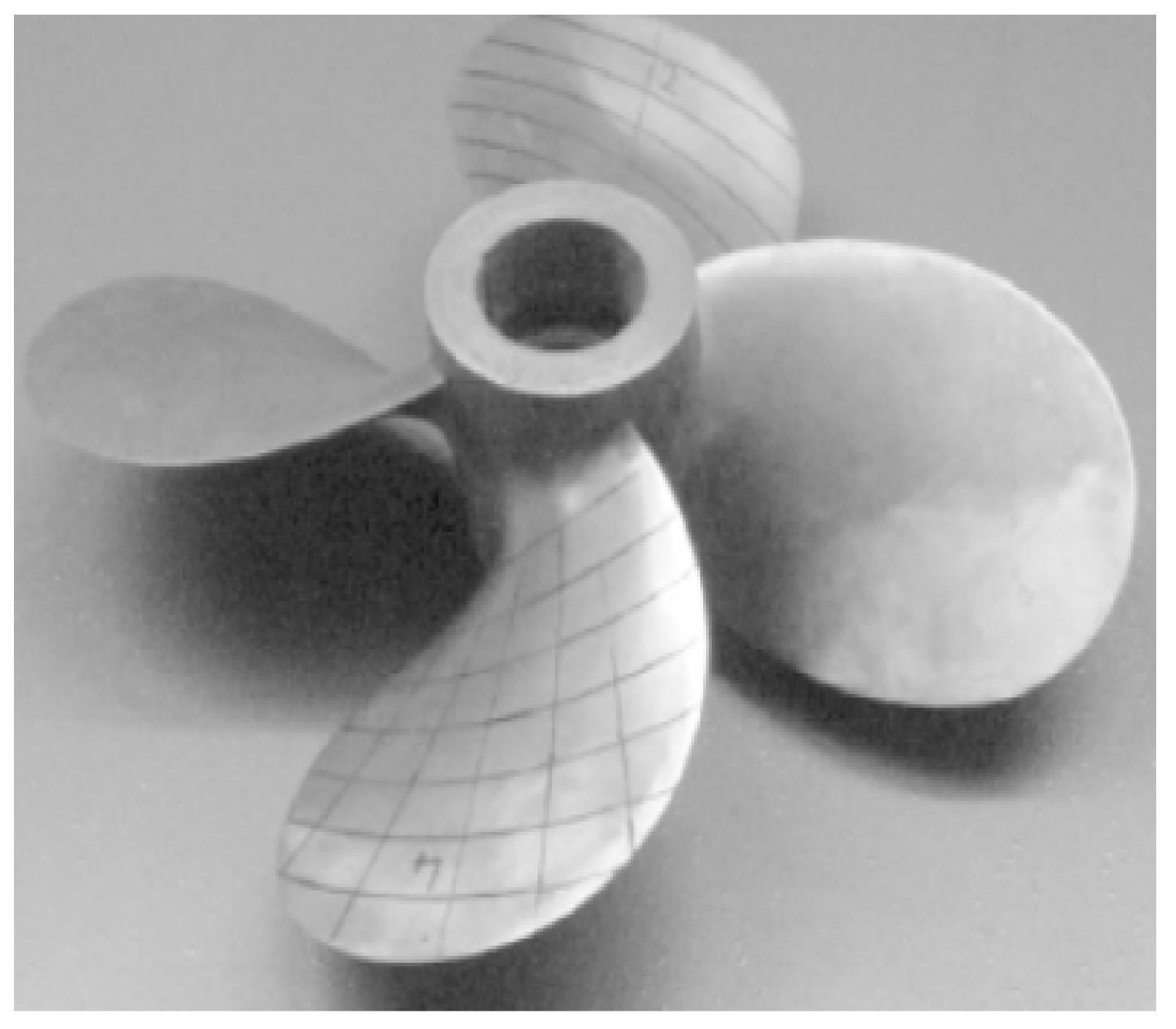
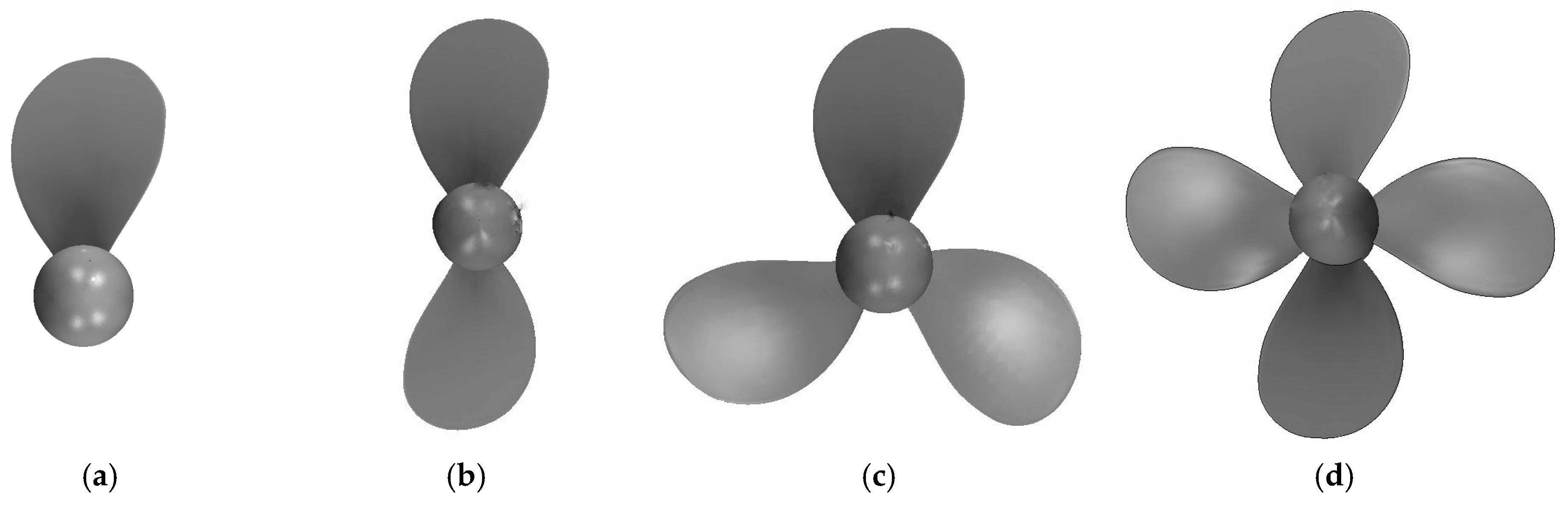
3.1. Propeller Parameters

The main geometric parameters of model propeller INSEAN E779A in the present study are listed in Table 1. The blade characteristics are shown in Table 2. The geometry of INSEAN E779A is shown in Figure 1. More geometric details can be found in the study by Salvatore et al. [25]. Four propellers having the same blade geometries as INSEAN E779A but different blade number k, which are shown in Figure 2.
Where R is the radius, r is the radial section, cb is the chord of the blade, tmax is the maximum thickness, and Rb is the rake. The rake is positive backward. Skew is indicated by the distance of the blade leading edge from the blade reference line xLE and the distance of the maximum thickness abscissa from the blade reference line xtmax. In the geometry used in the present study, there are no rounded corners considered in the leading edge and trailing edge.

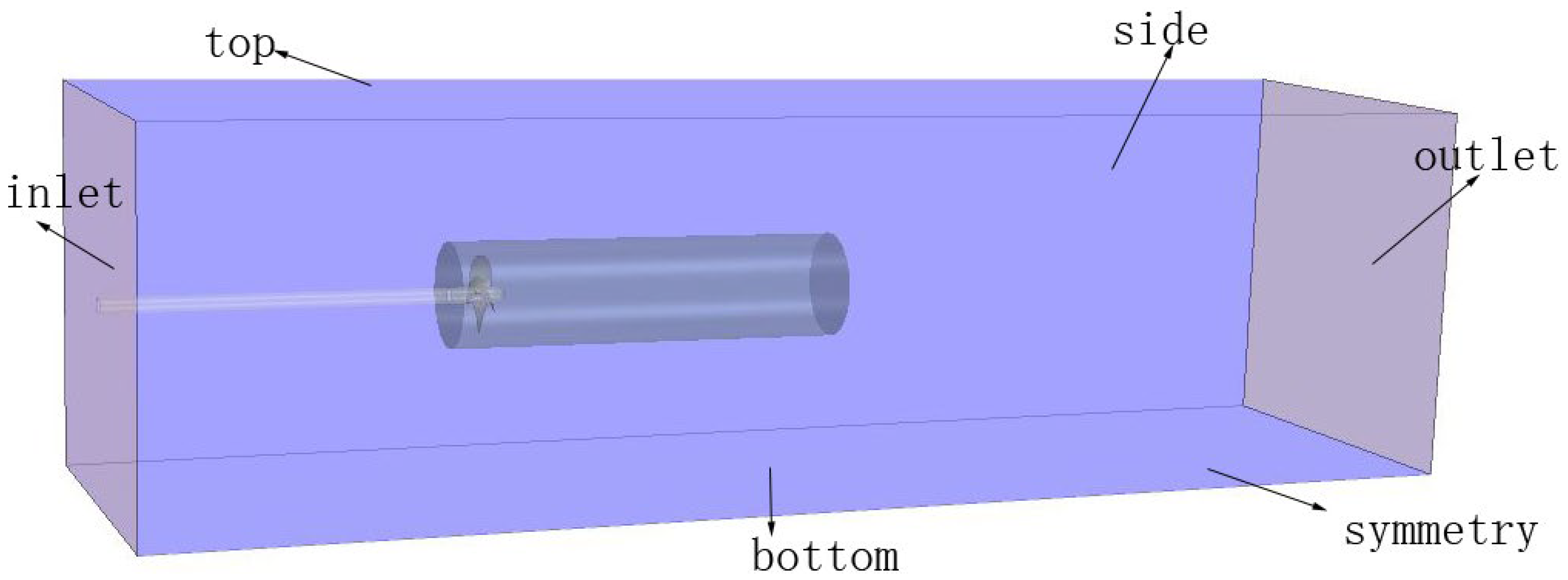
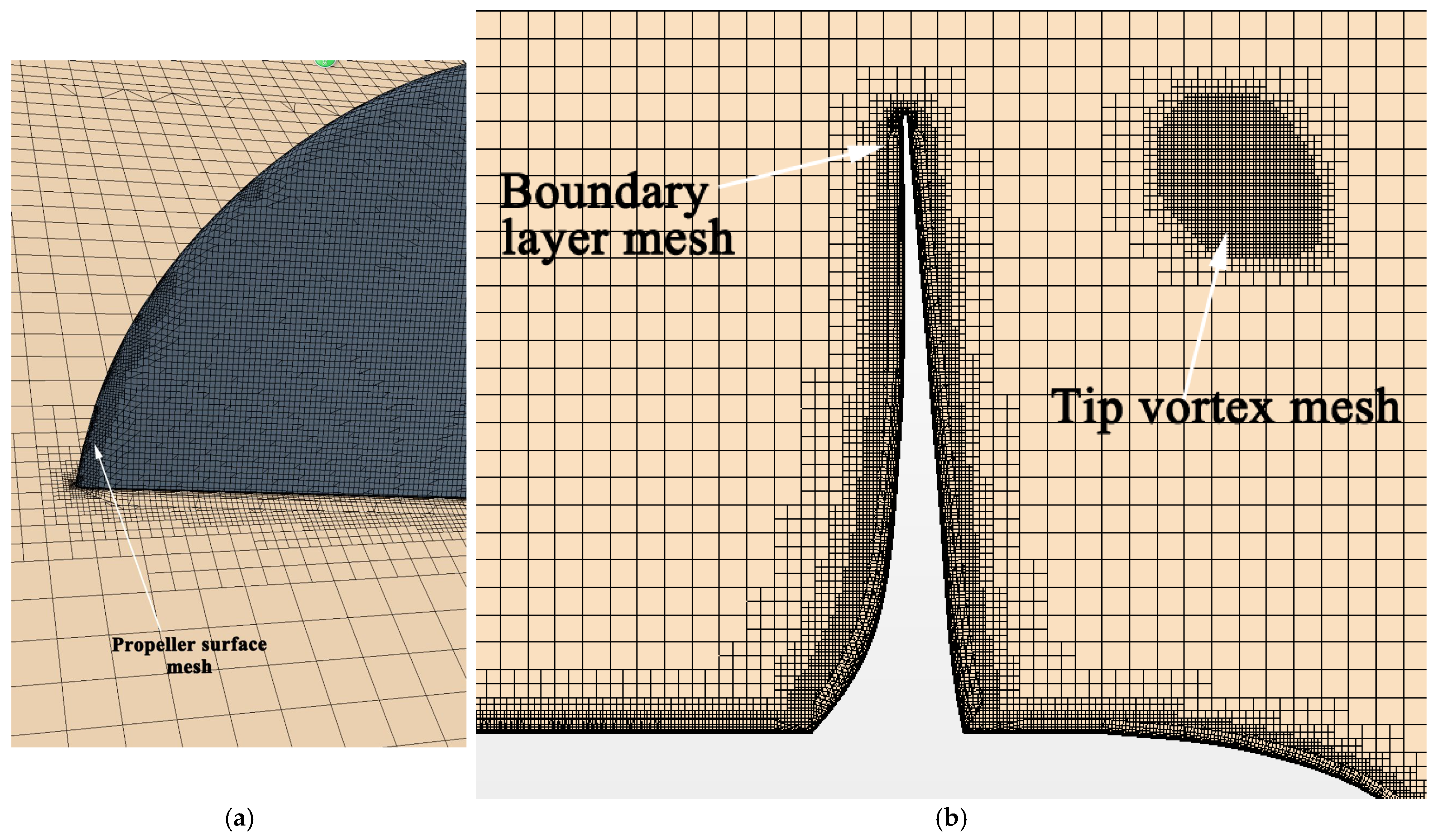
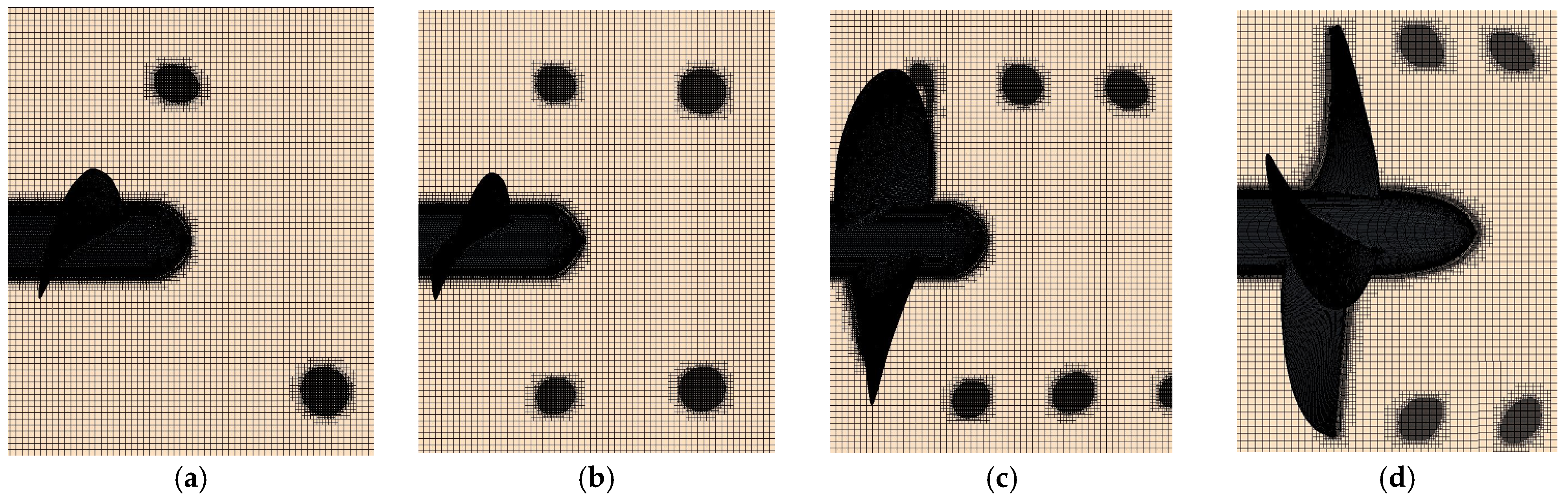
3.2. Meshing and Boundary Conditions

As shown in Figure 3, the computational domain is divided into a rotational domain containing the propeller and the stationary domain. The horizontal distances between the propeller center and the inlet and outlet of the stationary domain are 5D and 13D, respectively. The width and height are both 5D. The diameter and length of the rotational domain are 1.4D and 5D, respectively. The inlet and outlet are set as velocity inlet and pressure outlet. The rest boundaries of the domain are symmetrical planes. The blade surface is assumed to be non-slip and impenetrable. The surface of the rotational domain is defined as a sliding interface. The advance velocity coefficient of the propeller is defined as J = U / ( n D ) , where D is the propeller diameter, n is the propeller rotation speed, and U is the inflow speed. Different advance coefficients are obtained by changing the inflow speed. The cavitation number is defined as σ = ( p o p v ) / ( 0.5 ρ U 2 ) , where p0 is the far-field reference pressure, pv is the saturated vapor pressure, and ρl is the density of water. The present study is carried out in fresh water. The temperature is 25 °C.
Figure 4 shows the surface and boundary layer grids of the blade. The maximum element size of the rotational domain is 0.004 m. There are 12 layers of boundary layer mesh. The first boundary layer mesh is obtained by y+ of 0.8. Trim cells are used to mesh the rotating and the stationary domains. All y+ wall treatment models are used to solve the turbulence in the boundary layer. The cavitating tip vortex is thin and needs special treatment. To save element numbers, preliminary simulation is performed to estimate the shape and trajectory of the tip vortex tubes. We assumed the tip vortex cavitation is completely contained in tip vortex tubes obtained by Q-Criterion ≥ 2000/s2, which is shown in Figure 5.
Then the spiral tube refinement is carried out to obtain tip vortex cavitation. A maximum element size of 0.002D (i.e., 0.5 mm) is used for the blade surface and spiral tube refinement area. The element size and cell number before and after spiral tube refinement are listed in Table 3. As a result, the cell’s number of simulations aimed at the 4-bladed propeller reached approximately 22.02 million. Figure 6 shows the mesh details after spiral tube refinement with different blade numbers.
To analyze the uncertainty of the grid, simulations are carried out under the following grids: fine, medium, and coarse. The grid refinement ratio is 1.2. In Table 4, convergence ratio RG is 0.3655 and 0.3851, respectively. Results indicate discrepancies decreased with cell size. Hence, considering the computational cost and accuracy, the grid medium is employed for further simulation.

4. Results and Discussion

4.1. Hydrodynamic Performance

Thrust coefficient K T = T / ( ρ n 2 D 4 ) , torque coefficient K Q = Q / ( ρ n 2 D 5 ) , and efficiency η = J K T / ( 2 π K Q ) are defined based on thrust T and torque Q of the propeller obtained under advance coefficients J = 0.4–1.1. Figure 7 shows the hydrodynamic performance of the four propellers with various blade numbers. CFD corresponds to the numerical simulation obtained by the present study, and EFD refers to the experiment results obtained by Felli et al. (2008) [21]. The numerical results under k = 2–4 are generally consistent with the experimental results, despite a slight error below 5%. It is shown that thrust and torque coefficients increase as the blade number increases, while the efficiency decreases. This indicates that interaction of blades negatively impacts the hydrodynamic performance, and the effect is stronger with more blades. The thrust coefficient KT1, torque coefficient KQ1, and efficiency η1 of a single blade are shown in Figure 8. The increasing blade number also takes a negative impact on the hydrodynamic performance of a single blade.

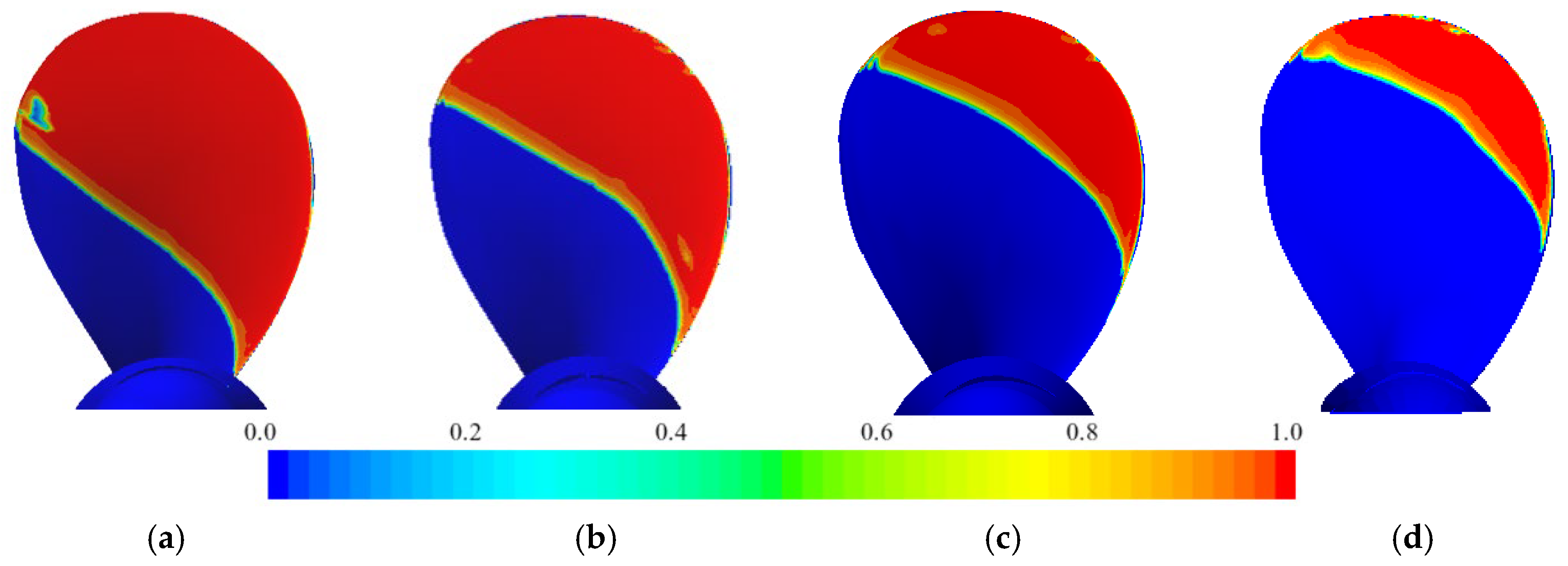
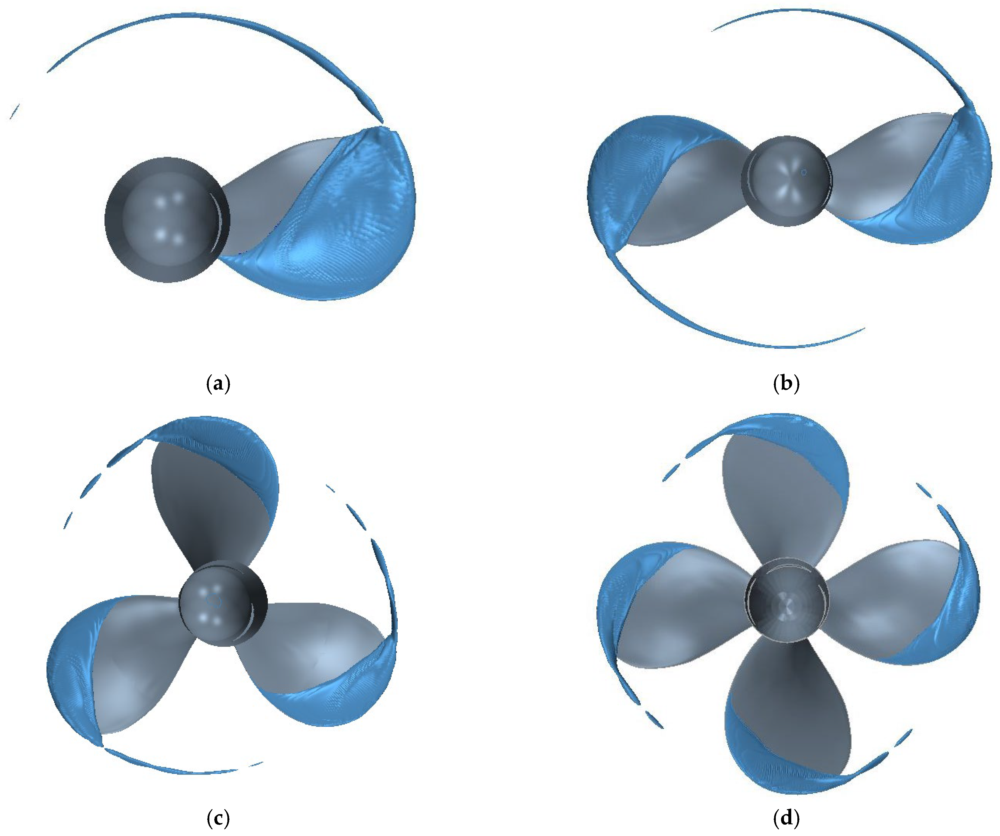
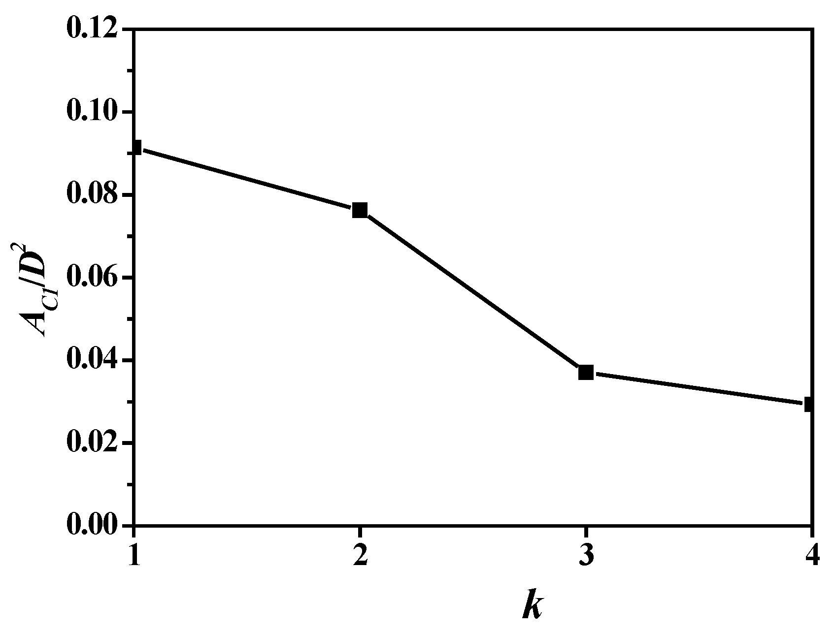
4.2. Cavitation Pattern

In this section, the simulation of cavitation is performed as J = 0.71 and σ = 1.763. The time step is Δt = 5 × 10⁻⁵ s, which corresponds to a propeller rotation angle of 0.18° per step. Figure 9 shows the cavitation on the back surface of the four propellers. Color means volume fraction of vapor. A higher blade number results in weaker cavitation on the blade surface. The cavitation covers most of the back surface when k = 1, while the cavitation only occurs over a limited area around the blade tip when k = 4. To qualitatively discuss the effect, the cavity lengths at different radii are shown in Figure 10. The linear velocity of blade sections increases as the radius increases. Thus, the cavitation tends to occur at outer sections with higher chord length. The weakest cavitation occurs at 0.2R, 0.25 R, 0.3 R, and 0.5 R for k = 1, 2, 3, and 4, respectively. Considering that the hub ratio is 0.2, the cavitation covers almost all the leading edge as k = 1. It is found from Figure 9 and Figure 10 that the cavitation around the blade is seriously affected by the blade number. Due to the tip vortex, cavitation is not only related to the flow separation but also to the strong three-dimensional flow over the blade tip.
The blade surface cavitation and tip vortex cavitation are shown in Figure 11. The cavitation outline is obtained by a volume fraction of 0.1. It can be seen that the cavity surface is not as smooth as expected, especially at the blade tip where the vortex cavitation detaches. Both blade surface cavitation and tip vortex cavitation are weakened as blade number increases. The tip vortex cavitation appears to be twisted spiral tubes. The vorticity is strong enough to resist the distortion when k = 1 and 2. The vorticity is further weakened when the blade number increases to 3 and 4. Further deformation and breaking can be observed before it vanishes. The cavitation profiles at section 0.7R are shown in Figure 12. The profile begins at the leading edge and ends at the blade surface. The profiles are shortened, but the shape keeps similar as the blade number increases.
Figure 13 and Figure 14 show the cavitation volume and area of the propeller blades regarding blade number. Figure 15 and Figure 16 show those of a single blade. Due to the reduction in the hydrodynamic loads on the single blade, the cavitation volume and area naturally decrease against the blade number. The cavitation volume and area reach their maximum as blade number k = 2.
The streamlines over the cavitation surface are shown in Figure 17. In the enlarged local view, the streamlines spirally swirled around the twisted tip vortex in the near field. In the far field, the twine is deterred by viscous convection and gradually dissipated. The numerical simulation of tip vortex cavitation can give satisfactory results, but tip vortex cavitation is far from being fully understood. Given that the cell size could not be decreased infinitely, the notable difference between the simulation and experimental results will remain. For example, the tip vortex cavitation can be extended far behind the blade.
The streamline details are shown in Figure 18, where U is the velocity. The streamlines at inner sections are quite regular in circumferential motion. However, at outer sections, strong three-dimensional flow causes inward motion in the radial direction and twining motion. A slight re-entrant can be found at the end of the sheet cavity.

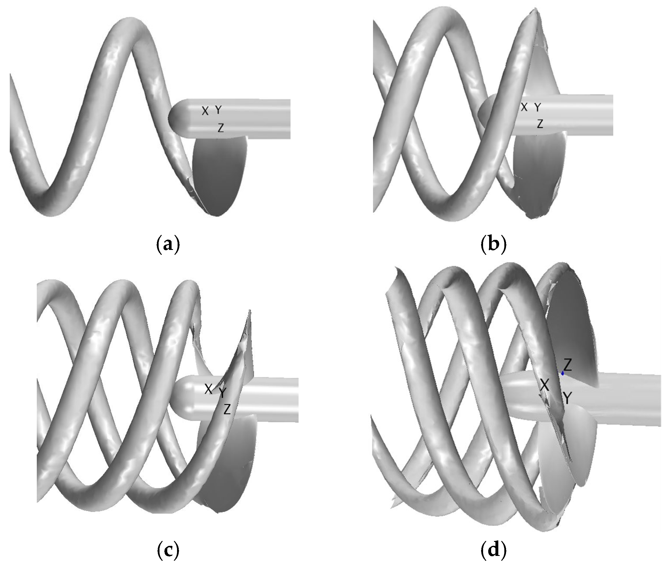
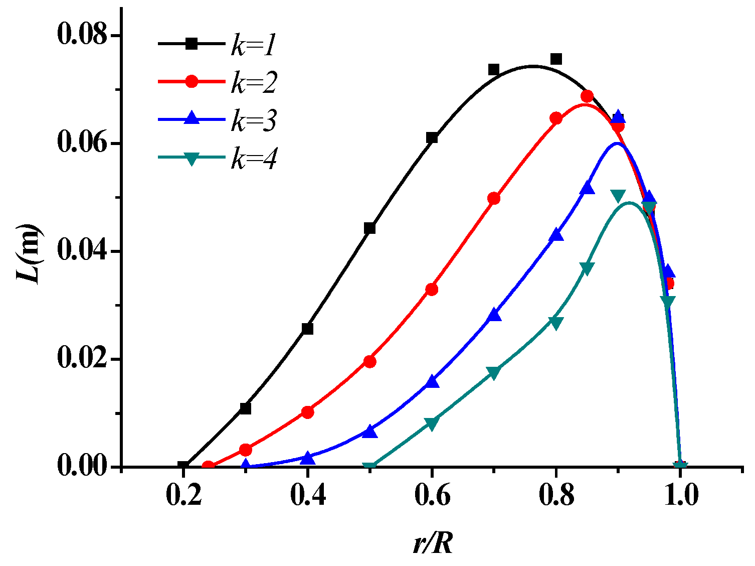
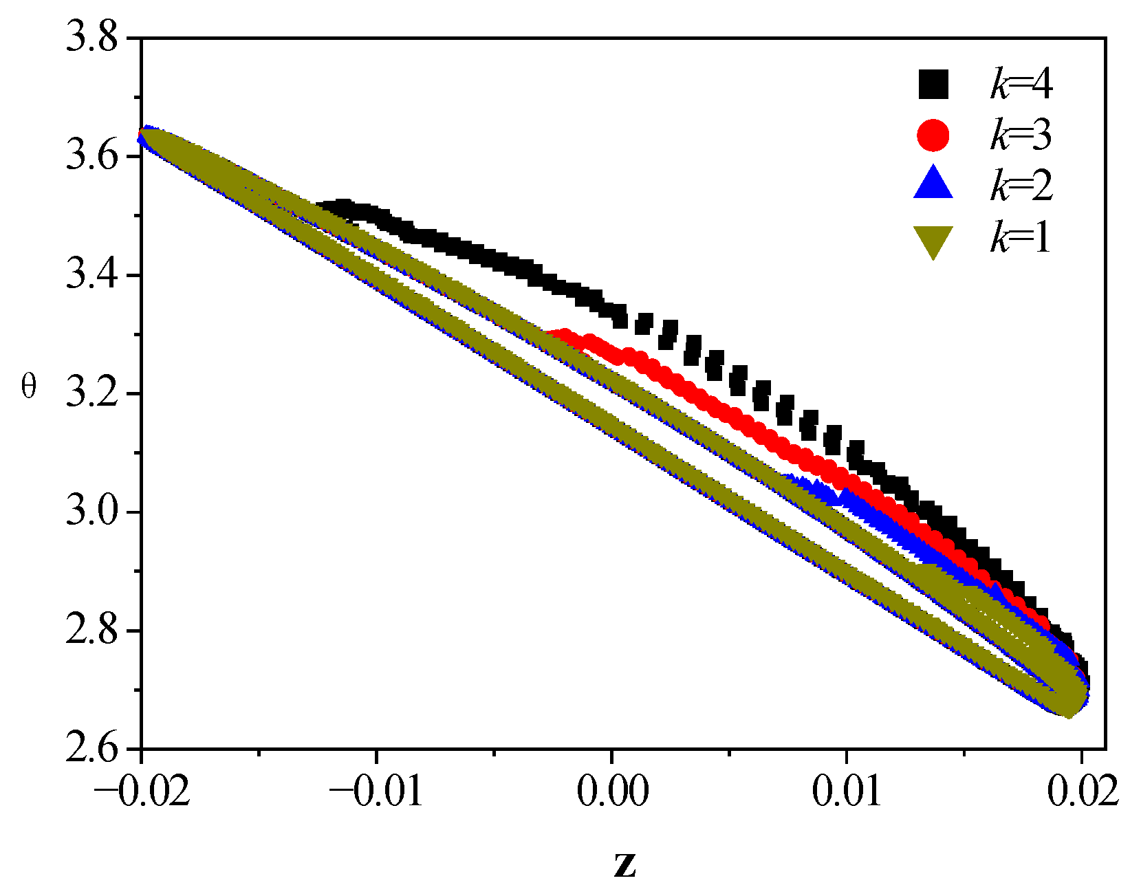
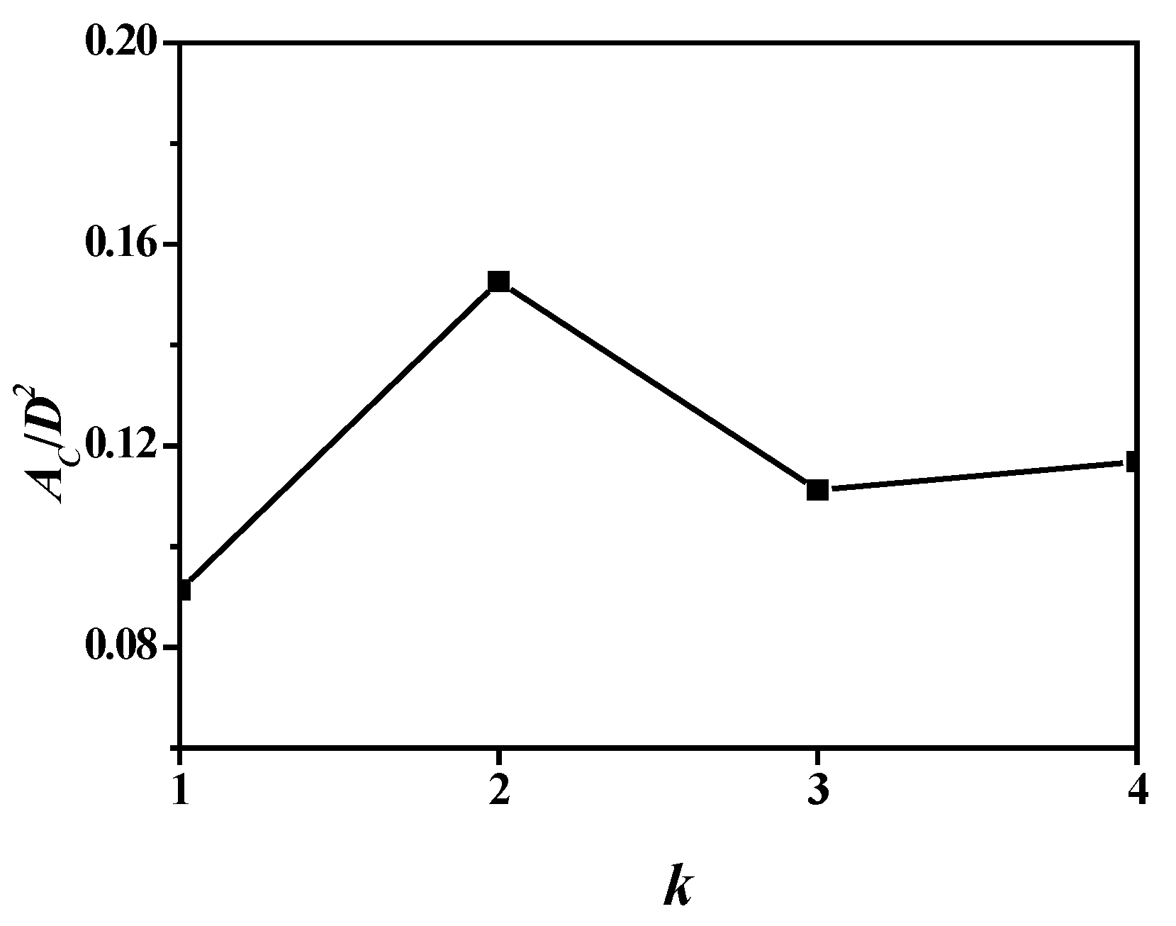
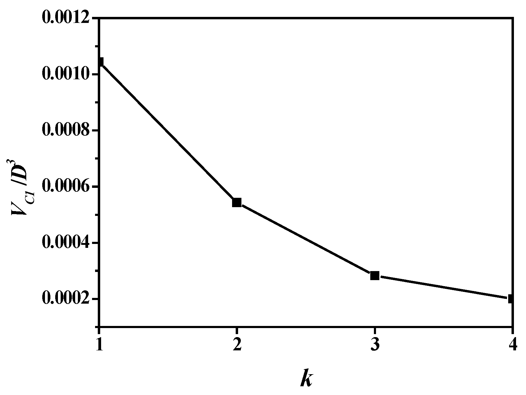
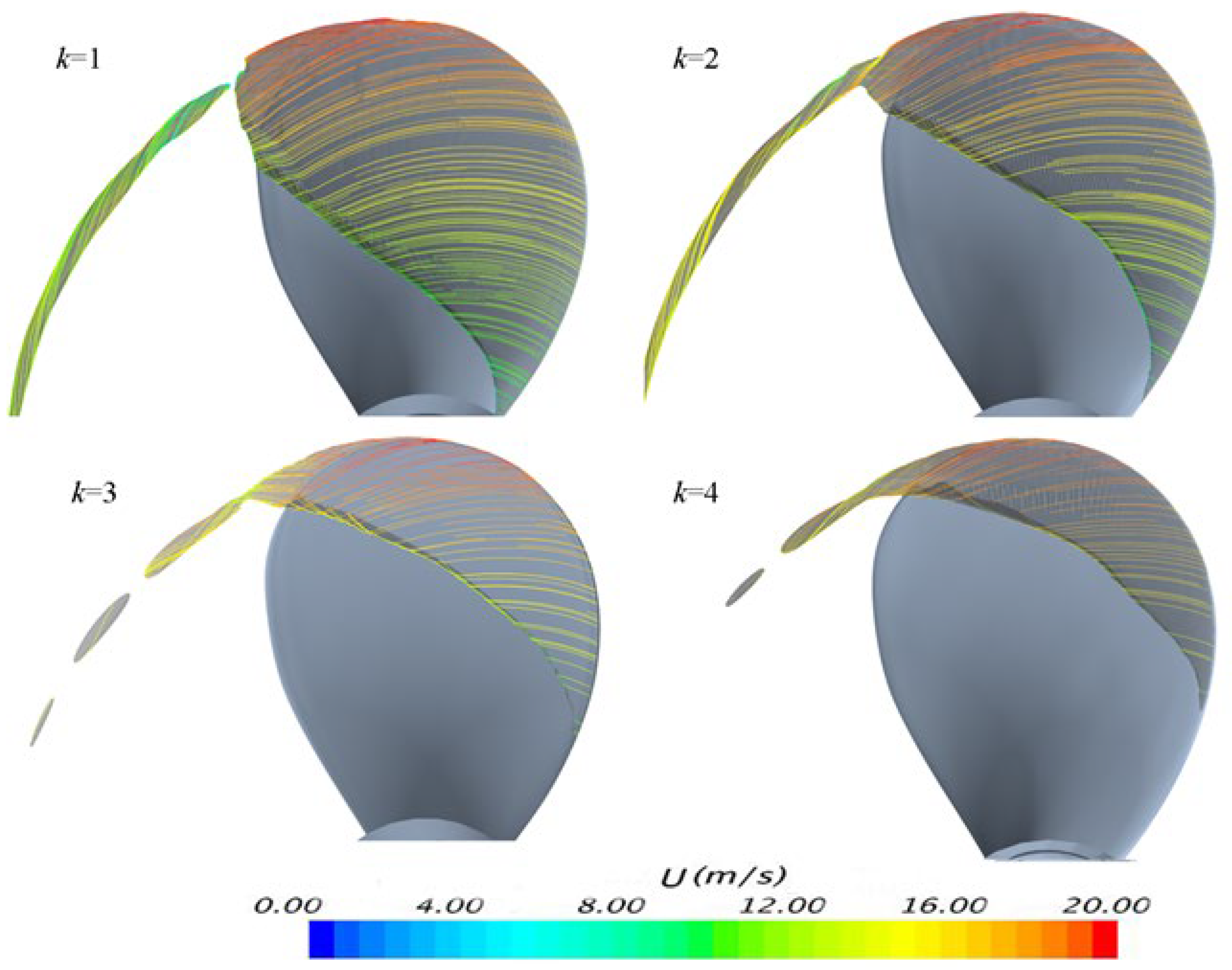
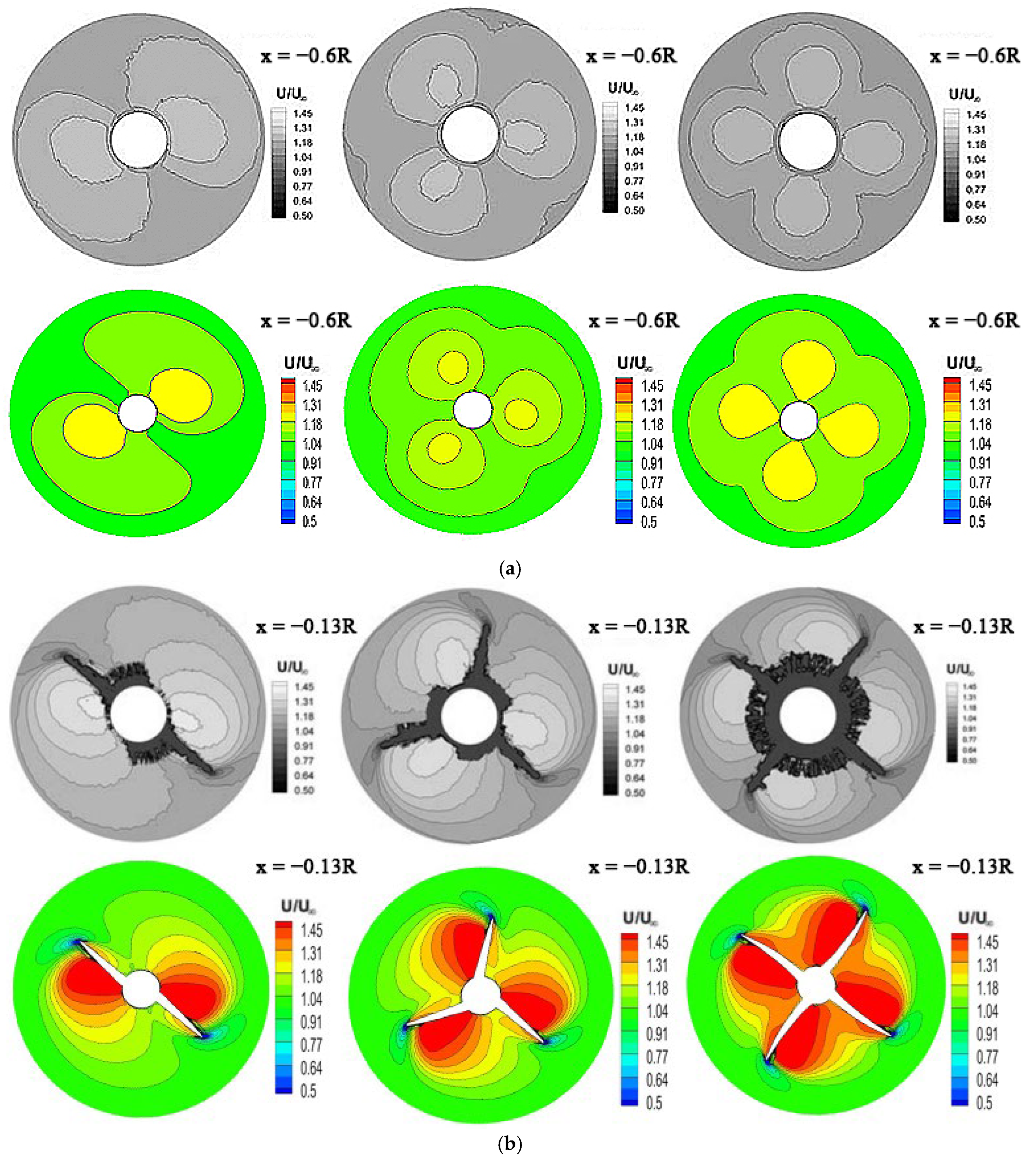
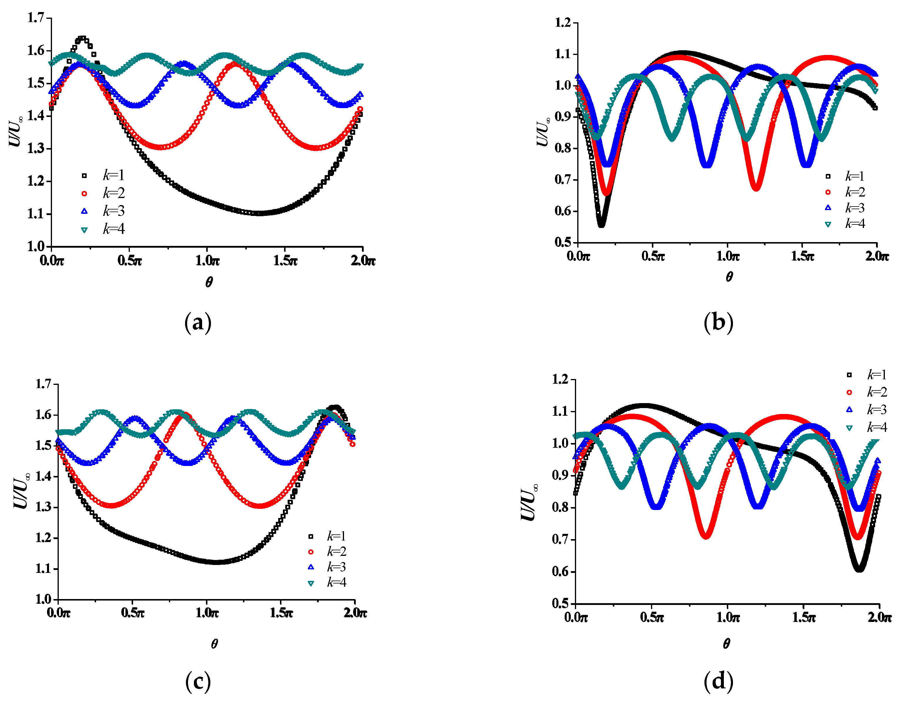
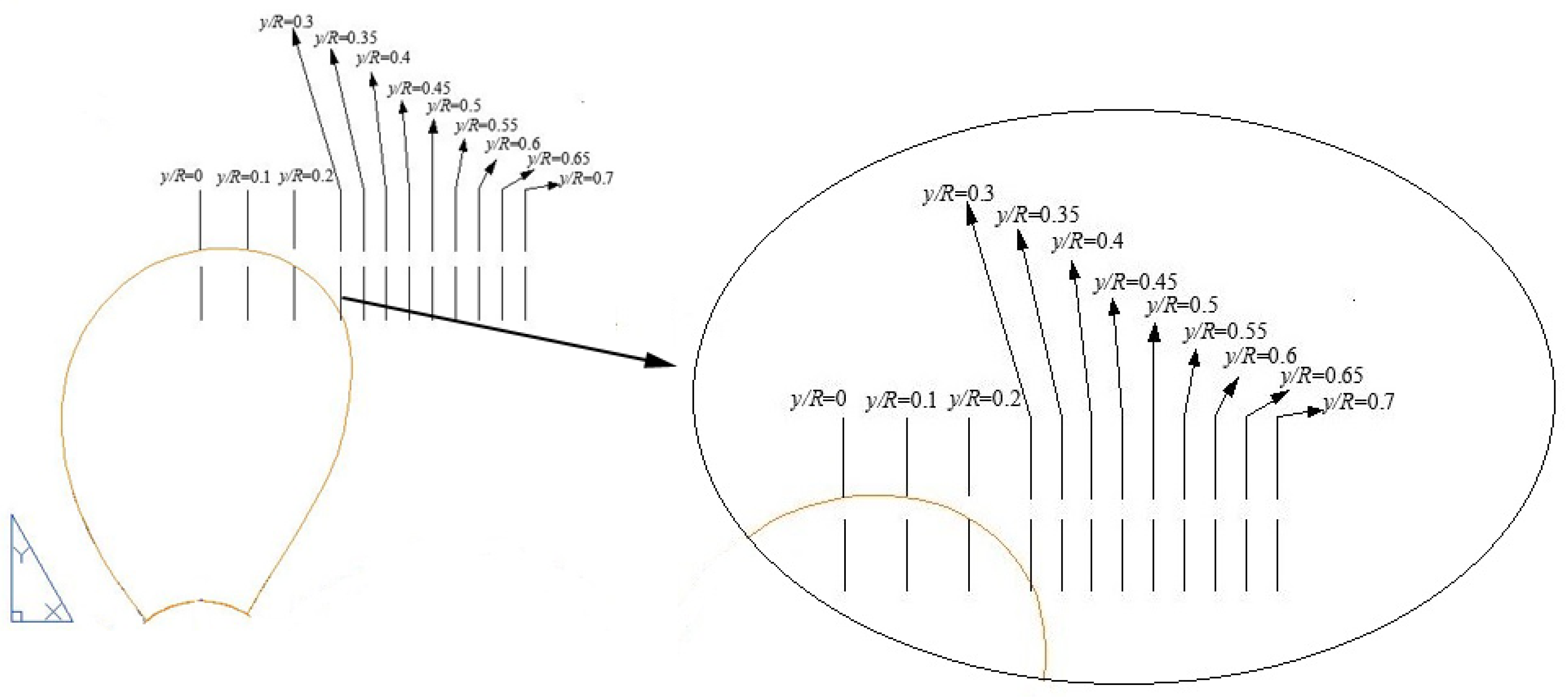
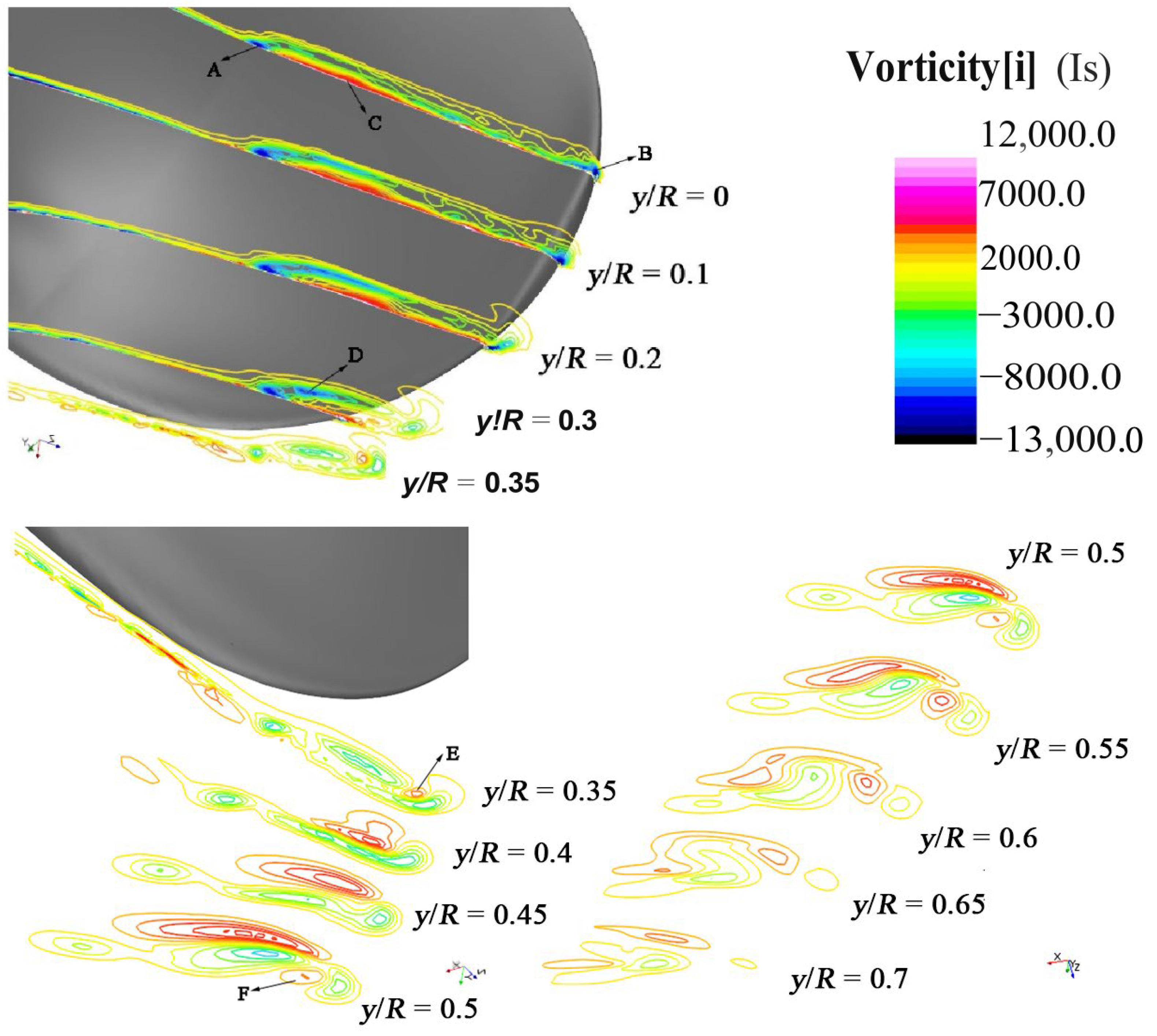
4.3. Flow-Field Analysis

In Figure 19, the propeller wake obtained by the present study is compared with experimental results obtained by Felli et al. [21]. The two circular cross-sections are located at x = −0.6R and x = −0.13R forward to the propeller disc. Generally, the numerical results agree very well with those by experiment. The periodicity of the wake corresponds to the blade number. The axial velocity is generally accelerated by the propeller, but deceleration can be observed in Figure 19b. It is also found from Figure 19 that the propeller wake is very much restricted within a circular radius. The variation in axial velocity strengthens when approaching the propeller.
To further quantitatively discuss the effect of blade number on the propeller wake, the velocity variation along four rings is presented in Figure 20. The radii of the rings are r = 0.7R and r = 1.0R, and the rings are located at x = 0.7R and x = 1.0R. It is found that the velocity fluctuation amplitude decreases as the blade number increases, but the periodicity increases corresponding to blade number. The flow is always accelerated at r = 0.7R, and the average velocity increases with blade number. However, at r = 1.0R, some fluid is decelerated. This indicates the strong effect of tip vortex on the axial velocity. The lowest velocity roughly corresponds to the vortical core.
Sections are employed to study the vortex structures on the blade surface and wake on a two-bladed propeller. In Figure 21, sections y/R = 0–0.3 are placed on the blade surface, sections y/R = 0.35–0.5 are placed in the near wake, and sections y/R = 0.5–0.7 are placed in the far wake. The axial vorticity contours are shown in Figure 22.
Figure 22 shows the evolution of the viscous boundary layer. Generally, the viscous layer is significantly thickened where the cavitation occurs. In Figure 22, three typical strong vorticity regions are numbered as A, B, and C. As shedding downstreamly, the cavitating layer is shortened but becomes thicker. Due to the change in tip shape, the vorticity dissipation of vortex B is faster. At y/R = 0–0.3, vortex C occurs between vortices A and B and on the side closer to vortex A. Vortex D gradually evolves above vortex C at y/R of 0–0.3. At y/R = 0.3, the core of vortex D is clear, as cavitation partially left the blade surface.
Figure 22 shows the evolution of the vortex detachment from the blade in the near-wake region as y/R = 0.35–0.5. As the cavitation completely detaches from the blade, vortices A and D dissipate rapidly, and vortex C almost completely dissipates, indicating that blade surface cavitation can hardly be maintained in the flow. At y/R = 0.35, secondary vortices occur and form a tip vortex, contributing to vortex D. Additionally, vortex E occurs between B and D. At y/R = 0.3–0.35, the pressure at the suction side is lower than that at the tip, causing flow to move from the blade tip to the suction side. Vortex E is derived by the rollup of the shear layer formed by flow moving from the tip to the suction side. After y/R = 0.4, vortex E gradually increased. At y/R = 0.45, its strength exceeds that of vortex B and becomes the main contribution of the tip vortex with a direction opposite that of vortex D. At y/R = 0.4–0.5, under the presence of vortex E, vortex B gradually changes its rotation direction, and vortex F occurs between vortices B and D at y/R = 0.5. Figure 22 shows streamwise vorticity at several planes in the far wake region as y/R = 0.55–0.7. In the far wake, the vortices continue to interact with each other, modifying its structure and gradually losing strength because of the viscous diffusion.

5. Conclusions

The effect of blade number on the tip vortex cavitation of the E779A marine propeller is investigated in the present study. The effect of blade number on the hydrodynamic efficiency, torque, thrust, and cavitation characteristics of the propeller was discussed. The effect of blade number on the axial velocity field is consistent with experimental results. It can be found that the blade surface cavitation and tip vortex cavitation can be greatly mitigated by increasing the blade number. However, the increase in blade number causes the reduction in propeller efficiency. Given that the element number could not be increased infinitely, which limits the application of now available numerical methods. More efficient numerical methods should be contributed to the numerical study of propeller tip vortex cavitation.

Author Contributions

Conceptualization, W.L. and J.H.; Software, Y.W.; Validation, B.F.; Investigation, Y.X. and C.D.; Writing–original draft, Y.W. and W.Z.; Writing–review & editing, Y.X. and B.F.; Visualization, Y.X. and B.F.; Supervision, J.H. All authors have read and agreed to the published version of the manuscript.

Funding

This research received no external funding.

Data Availability Statement

The original contributions presented in this study are included in the article. Further inquiries can be directed to the corresponding author.

Conflicts of Interest

The authors declare no conflict of interest.

References

  1. Huse, E. Pressure Fluctuations on the Hull Induced by Cavitating Propellers; Technical Report 111, Norwegian Ship Model Experiment Tank; Trondheim University: Trondheim, Norway, 1972. [Google Scholar]
  2. Kinnas, S.A.; Hsin, C.-Y. Boundary element method for the analysis of the unsteady flow around extreme propeller geometries. AIAA J. 1992, 30, 688–696. [Google Scholar] [CrossRef]
  3. Fine, N.E.; Kinnas, S.A. A boundary element method for the analysis of the flow around 3-D cavitating hydrofoils. J. Ship Res. 1993, 37, 213–224. [Google Scholar] [CrossRef]
  4. Lee, H. Modeling of Unsteady Wake Alignment and Developed Tip Vortex Cavitation. Doctoral Dissertation, University of Texas at Austin, Austin, TX, USA, August 2002. [Google Scholar]
  5. Sharma, A. Numerical Modeling of a Hydrofoil or a Marine Propeller Undergoing Unsteady Motion via a Panel Method and RANS. Doctoral Dissertation, University of Texas at Austin, Austin, TX, USA, June 2011. [Google Scholar]
  6. Chang, Y.C.; Hu, C.N.; Tu, J.C.; Chow, Y.C. Experimental investigation and numerical prediction of cavitation incurred on propeller surfaces. J. Hydrodyn. 2010, 22, 722–727. [Google Scholar] [CrossRef]
  7. Sato, K.; Ohshima, A.; Egashira, H.; Takano, S. Numerical Prediction of Cavitation and Pressure Fluctuation Around Marine Propeller. In Proceedings of the 7th International Symposium on Cavitation, Ann Arbor, MI, USA, 16–20 August 2009. [Google Scholar]
  8. Feng, X.; Lu, J. Effects of balanced skew and biased skew on the cavitation characteristics and pressure fluctuations of the marine propeller. Ocean Eng. 2019, 184, 184–192. [Google Scholar] [CrossRef]
  9. Hu, J.; Zhang, W.; Wang, C.; Sun, S.; Guo, C. Impact of skew on propeller tip vortex cavitation. Ocean Eng. 2021, 220, 108479. [Google Scholar] [CrossRef]
  10. Jeong, S.; Hong, S.; Song, J.; Kwon, H.; Seol, H. Numerical method to determine the cavitation inception speed of a submarine propeller based on the noise obtained from bubble dynamics. Ocean Eng. 2021, 245, 110464. [Google Scholar] [CrossRef]
  11. Viitanen, V.; Sipilä, T.; Sánchez-Caja, A.; Siikonen, T. CFD predictions of unsteady cavitation for a marine propeller in oblique inflow. Ocean Eng. 2022, 266, 112596. [Google Scholar] [CrossRef]
  12. Li, M.; Hong, Y.; Si, B.; Ding, Y.; Tang, Z.; Wang, R.; He, X. Numerical and experimental study of the cavitation performance of a composite propeller. Phys. Fluids 2024, 36, 103303. [Google Scholar] [CrossRef]
  13. Zhu, W.; Li, Z.; Ding, R. Effect of pitch ratio on the cavitation of controllable pitch propeller. Ocean Eng. 2024, 293, 116692. [Google Scholar] [CrossRef]
  14. Li, M.M.; Hong, Y.; Zhang, H.L.; Wang, R.G.; He, X.D. The numerical research on cavitation performance of the composite propeller under uniform and non-uniform inflow. Ocean Eng. 2025, 322, 120399. [Google Scholar] [CrossRef]
  15. Muscari, R.; Di Mascio, A.; Verzicco, R. Modeling of vortex dynamics in the wake of a marine propeller. Comput. Fluids 2013, 73, 65–79. [Google Scholar] [CrossRef]
  16. Di Felice, F.; Felli, M.; Liefvendahl, M.; Svennberg, U. Numerical and experimental analysis of the wake behavior of a generic submarine propeller. Prism 2009, 1, 158. [Google Scholar]
  17. Bensow, R.E.; Bark, G. Implicit LES predictions of the cavitating flow on a propeller. J. Fluids Eng. 2010, 132, 041302. [Google Scholar] [CrossRef]
  18. Yilmaz, N.; Atlar, M.; Fitzsimmons, P.A. An Improved Tip Vortex Cavitation Model for Propeller-Rudder Interaction. In Proceedings of the 10th International Cavitation Symposium (CAV2018), Baltimore, MD, USA, 14–16 May 2018. [Google Scholar]
  19. Yimaz, N.; Atlar, M.; Khorasanchi, M. An improved Mesh Adaption and Refinement approach to Cavitation Simulation (MARCS) of propellers. Ocean Eng. 2019, 171, 139–150. [Google Scholar] [CrossRef]
  20. Nouri, N.M.; Mohammadi, S. A multi-objective approach for determining the number of blades on a NACA marine propeller. Brodogr. Teor. Praksa Brodogr. Pomor. Teh. 2016, 67, 15–32. [Google Scholar]
  21. Felli, M.; Guj, G.; Camussi, R. Effect of the number of blades on propeller wake evolution. Exp. Fluids 2008, 44, 409–418. [Google Scholar] [CrossRef]
  22. Zhu, Z.F. Numerical Study of Effect of the Number of Propeller Blades on Cavitating Flow. In Advanced Materials Research; Trans Tech Publications: Wollerau, Switzerland, 2013; Volume 716, pp. 739–743. [Google Scholar]
  23. Bakhtiari, M.; Ghassemi, H. 2019. Numerical analysis on effects of blade number on hydrodynamic performance of low-pitch marine cycloidal propeller. Proc. Inst. Mech. Eng. Part M J. Eng. Marit. Environ. 2019, 234, 490–501. [Google Scholar]
  24. Schnerr, G.H.; Sauer, J. Physical and Numerical Modeling of Unsteady Cavitation Dynamics. In Proceedings of the Fourth International Conference on Multiphase Flow (ICMF), New Orleans, LA, USA, 27 May–1 June 2001. [Google Scholar]
  25. Salvatore, F.; Pereira, F.; Felli, M.; Calcagni, D.; Di Felice, F. Description of the INSEAN E779A Propeller Experimental Dataset (Version 1). Zenodo. INSEAN Tech. Rep., 2006–2085. Available online: https://doi.org/10.5281/zenodo.6077997 (accessed on 1 May 2015).
Figure 1. INSEAN E779A model propeller.
Jmse 13 00915 g001
Figure 2. Four model propellers with different blade numbers: (a) k = 1, (b) k = 2, (c) k = 3, and (d) k = 4.
Jmse 13 00915 g002
Figure 3. Computational domain.
Jmse 13 00915 g003
Figure 4. Mesh details of the propeller: (a) transverse view of the mesh and (b) cross view of the mesh.
Jmse 13 00915 g004
Figure 5. Preliminary simulation of propeller tip vortex tubes: (a) k = 1, (b) k = 2, (c) k = 3, and (d) k = 4.
Jmse 13 00915 g005
Figure 6. Mesh details with spiral refinement: (a) k = 1, (b) k = 2, (c) k = 3, and (d) k = 4.
Jmse 13 00915 g006
Figure 7. Hydrodynamic performance of the propeller.
Jmse 13 00915 g007
Figure 8. Hydrodynamic performance of a single blade.
Jmse 13 00915 g008
Figure 9. Blade surface cavitation: (a) k = 1, (b) k = 2, (c) k = 3, and (d) k = 4.
Jmse 13 00915 g009
Figure 10. Cavitation length for different numbers of propeller blades.
Jmse 13 00915 g010
Figure 11. Three-dimensional view of blade surface cavitation and tip vortex cavitation: (a) k = 1, (b) k = 2, (c) k = 3, and (d) k = 4.
Jmse 13 00915 g011
Figure 12. Cavitation profiles at the 0.7R section for different blade numbers.
Jmse 13 00915 g012
Figure 13. Cavitation volume variation in the propeller.
Jmse 13 00915 g013
Figure 14. Cavitation area variation in the propeller.
Jmse 13 00915 g014
Figure 15. Cavitation volume variation in a single blade.
Jmse 13 00915 g015
Figure 16. Cavitation area variation in a single blade.
Jmse 13 00915 g016
Figure 17. Streamlines over cavitating surface: (a) overall view and (b) local view.
Jmse 13 00915 g017
Figure 18. Streamlines over blade surface.
Jmse 13 00915 g018
Figure 19. Normalized axial velocity of propeller wake: (a) x = −0.6R and (b) x = −0.13R.
Jmse 13 00915 g019
Figure 20. Velocity distribution of propeller wake: (a) x = 0.7R, r = 0.7R; (b) x = 0.7R, r = 1.0R; (c) x = 1.0R, r = 0.7R; and (d) x = 1.0R, r = 1.0R.
Jmse 13 00915 g020
Figure 21. Location of vorticity contour section.
Jmse 13 00915 g021
Figure 22. Contours of axial vorticity.
Jmse 13 00915 g022
Table 1. Geometric parameters of model propeller (Salvatore et al., 2006 [25]).
ParameterValue
Diameter D227 mm
Pitch ratio P1.1
Disc ratio S0.689
Hub diameter d45.53 mm
Rotational speed n25 rps
Table 2. Blade characteristics of the E779A propeller.
r/RP/Dcb/DxLE/Dtmax/Dxtmax/DRb/D
0.26401.11180.27840.16040.04030.1763−0.0060
0.35201.12040.30800.17080.03120.1047−0.0107
0.44001.12020.33570.18020.02570.0867−0.0144
0.52801.11670.36000.18720.02120.0699−0.0179
0.61601.11470.37670.18970.01670.1035−0.0216
0.70401.11730.37840.18490.01290.0386−0.0250
0.79201.11740.36340.16950.00970.0166−0.0288
0.88001.11020.31700.13450.0063−0.0757−0.0327
0.96801.11790.19170.05970.0039−0.1884−0.0364
0.99001.12610.11570.01620.0033−0.4599−0.0376
0.99881.12610.0491−0.02070.0019−0.9726−0.0384
Table 3. Element size and number of the four model propellers.
Number of Blades kElement SizeNumber Before Spiral Tube Refinement Number After Spiral Tube Refinement
10.002D4.52 million13.52 million
20.002D9.86 million17.19 million
30.002D11.32 million19.52 million
40.002D12.84 million22.02 million
Table 4. Uncertainty analysis of grid.
GridsCellsKTErrorRGKQErrorRG
Fine30.21 M0.22700.5286%0.36550.42130.8070%0.3851
Medium22.02 M0.22821.4461%0.42472.0956%
Coarse13.84 M0.2315--0.4336--
Disclaimer/Publisher’s Note: The statements, opinions and data contained in all publications are solely those of the individual author(s) and contributor(s) and not of MDPI and/or the editor(s). MDPI and/or the editor(s) disclaim responsibility for any injury to people or property resulting from any ideas, methods, instructions or products referred to in the content.

