1. Introduction
With the increasing consumption of non-renewable energy sources such as coal and oil, coupled with worsening environmental pollution, there has been a global shift toward clean and renewable energy sources. Among these, wind energy has gained significant attention. Compared to onshore wind energy, offshore wind energy offers advantages such as higher turbulence intensity, reduced noise pollution, and more abundant resources [
1,
2].
In shallow waters, offshore wind turbines are typically installed on fixed foundations [
3,
4]. However, as water depth increases, the cost of fixed foundations rises exponentially, making floating foundations a more economically viable alternative [
5]. Common types of floating offshore platforms include semi-submersible platforms, spar platforms, and tension-leg platforms (TLPs). Among these, TLPs exhibit superior stability due to their high stiffness in the vertical direction, which effectively controls heave and pitch motions, ensuring the stable operation of the wind turbine (WT) [
6,
7,
8].
The installation of offshore wind turbines is a highly demanding technical operation, requiring extreme precision regardless of whether a segmented or integrated installation approach is adopted [
9]. Typically, WT installation involves the use of jack-up crane vessels or floating crane vessels, with specific installation methods selected based on water depth, lifting capacity, and vessel performance, either independently or in combination [
10,
11,
12]. Various types of wind turbine installation vessels are available, and each project selects the most reasonable and cost-effective option based on crane capacity and load capability.
Significant research has been conducted on the installation of floating wind turbines. Liu et al. [
13] evaluated the dynamic response of two novel installation vessels—a catamaran and a small-waterplane-area twin hull (SWATH)—during the installation of a spar-type floating wind turbine, providing insights into vessel selection for offshore turbine installation. Hong et al. [
14] proposed an innovative on-site installation method for floating offshore wind turbines, utilizing a catamaran to assemble the turbine directly at the operation site, thereby reducing dependence on port infrastructure. They introduced a fender system and pretension wires to optimize the dynamic response during turbine docking, offering a novel installation strategy for floating wind turbines. Liu et al. [
15] compared the dynamic responses of the NREL 5 MW and IEA 15 MW offshore wind turbine installation systems, analyzing the impact of waves and wind on the motion of catamarans and spar platforms, as well as the relative motion at connection points, to enhance installation stability. Hassan et al. [
16] assessed the dynamic response and adaptability of a novel floating monohull vessel (Nordic Wind) during offshore wind turbine installation, focusing on the effects of wind, waves, and currents on the motion responses of both the installation vessel and the floating foundation, as well as the loading conditions of the gripper system. Their findings provide insights into the design and operational strategies of future wind turbine installation vessels. Ma et al. [
17] proposed an integrated transportation and installation method for the tower–nacelle–rotor (TNR) assembly, investigating the influence of environmental loads on the turbine lowering process. They analyzed the interactions between components and the foundation during lifting, as well as the effects of lowering speed and timing on the system’s dynamic response, contributing to advancements in floating wind turbine installation techniques.
Based on this background, although various installation strategies for floating offshore wind turbines have been proposed, research on floating foundations that facilitate both installation and removal remains limited. To address this gap, this study proposes a novel tension-leg dual-module offshore wind turbine system aimed at enhancing the ease of installation, removal, and maintenance. The system mainly consists of a DTU 10 MW wind turbine (WT) [
18] module and a supporting tension-leg platform (TLP) module. Considering the mechanical coupling effect and hydrodynamic coupling effect, this study focuses on the dynamic response during the installation and removal of the WT module. During the removal process of the WT module, the impact of different installation vessel configurations and key design parameters of the clamping device on the system’s dynamic response is analyzed. Preliminary optimization recommendations are provided based on these findings. The main results of this study can serve as a reference for the design, installation, and removal of floating wind turbines.
2. Theoretical Basis and Numerical Model
2.1. Conceptual Design of the Novel Tension-Leg Dual-Module Offshore Wind Turbine System
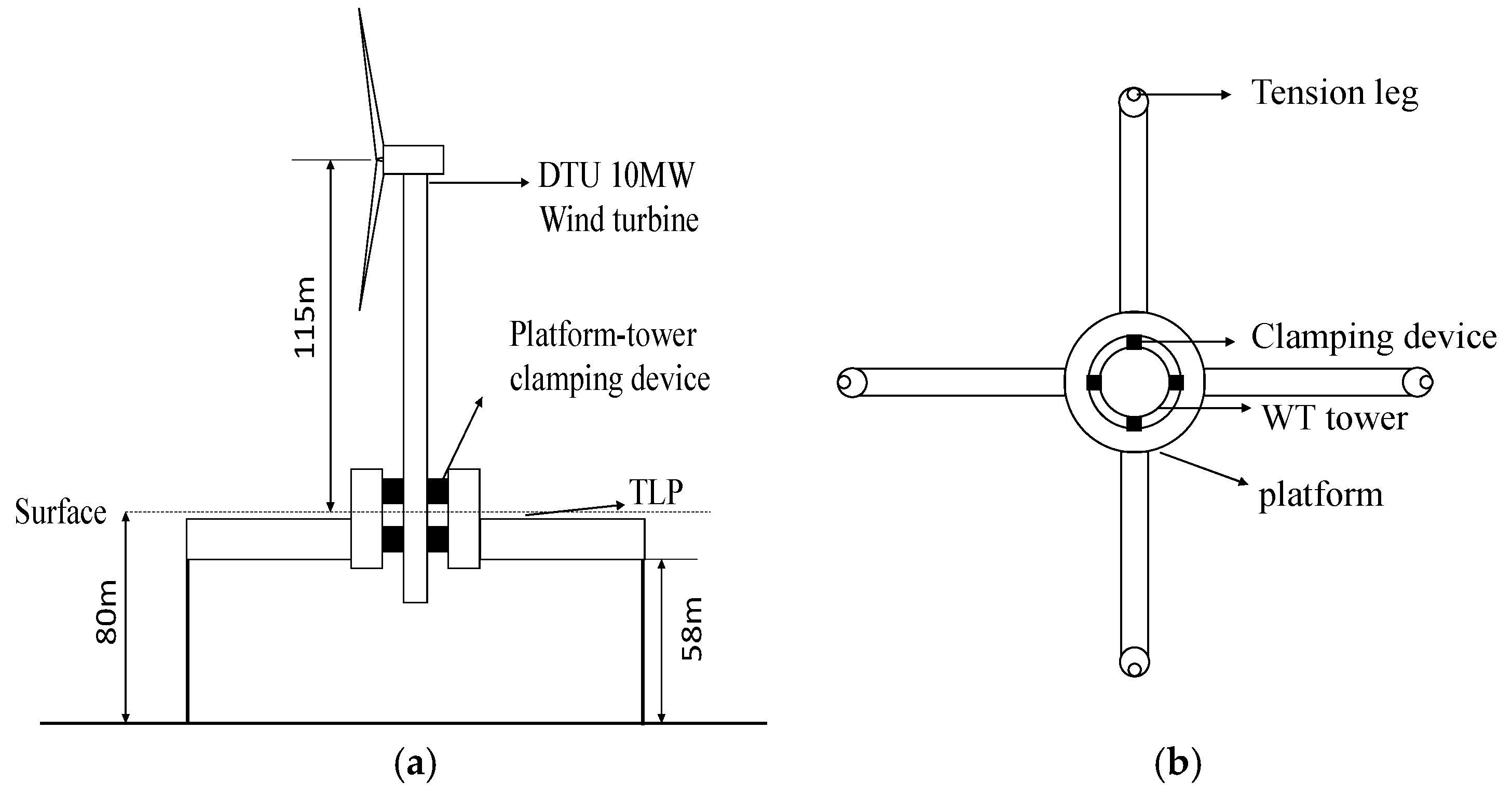
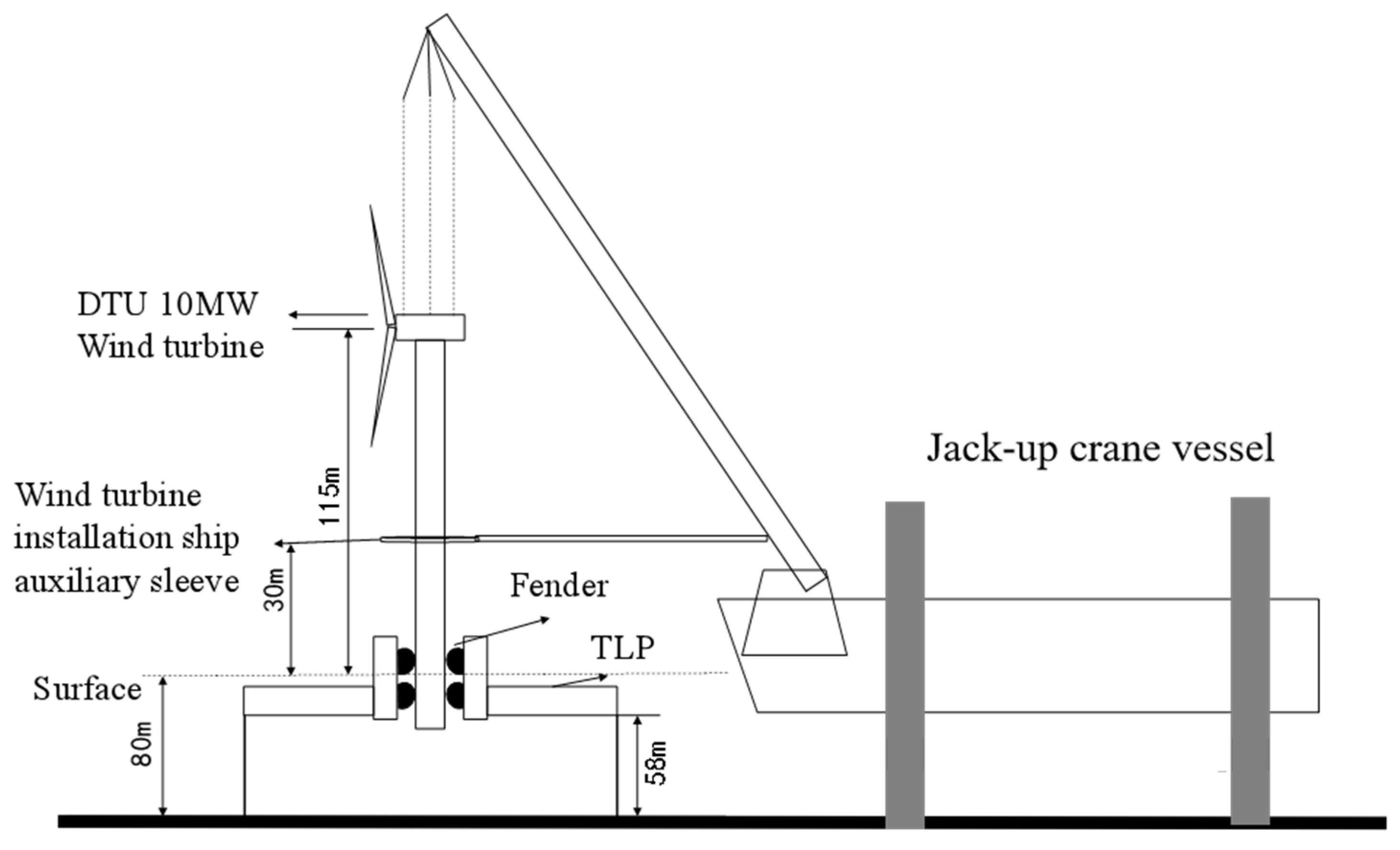
This study proposes a novel tension-leg dual-module offshore wind turbine system, which primarily consists of the following components:
- (1)
A DTU 10 MW floating wind turbine (WT) module.
Considering that the wind turbine is parked during both installation and removal processes, the detailed information of its aerodynamic performance during operation is not included here, but more detailed information of its aerodynamic performance can be found in reference [
18].
- (2)
A tension-leg platform (TLP) module.
- (3)
A clamping device that connects the TLP and the wind turbine support tower.
The DTU 10 MW wind turbine module, positioned at the center of the TLP module, exhibits a self-balancing characteristic through gravity and buoyancy equilibrium. The TLP module features a central column with a hollow cylindrical passage whose inner diameter is slightly larger than the outer diameter of the wind turbine tower, maintaining a clearance of 0.5 m. The TLP module and the WT module are securely connected via a vertically arranged multi-layer symmetric clamping device. The conceptual design of the system is illustrated in
Figure 1, and its primary design parameters are listed in
Table 1.
During the removal of the WT module, the clamping device must be released. To prevent collisions between the tower and the TLP central column during the upward extraction of the wind turbine, fenders are incorporated into the clamping device to absorb impact forces. The clamping devices are positioned at depths of 4 m and 8 m underwater to ensure secure fixation while allowing controlled removal.
2.2. Overview of the WT Installation Vessel
This study references the ORION I, a large-scale wind turbine installation vessel built by COSCO Shipping Co., Ltd., Shanghai, China, to investigate the installation and removal process of the proposed novel system. The ORION I is equipped with a 5000-ton full-rotation heavy-duty crane with a maximum lifting height of 170 m, capable of transporting the heaviest monopile foundations, jacket foundations, and various wind turbine components currently available on the market. It is one of the largest and most technologically advanced wind turbine installation vessels in the world.
Since detailed specifications of ORION I are not available, this study approximates the vessel as a simplified box-shaped structure for subsequent calculations. The key parameters used for this approximation are listed in
Table 2.
During the removal process of the WT module, cables are required to connect the installation vessel to the wind turbine tower. In this study, four cables are deployed at four sides of the wind turbine tower for controlled extraction. The wind turbine tower extends 35 m below the water surface, and to ensure its complete emergence, the simulation is configured to lift the turbine 40 m upward.
In the installation process, when the top of the wind turbine tower reaches 5 m above the water surface, the lower end is further lowered by 40 m to complete the installation process.
2.3. Hydrodynamic Model
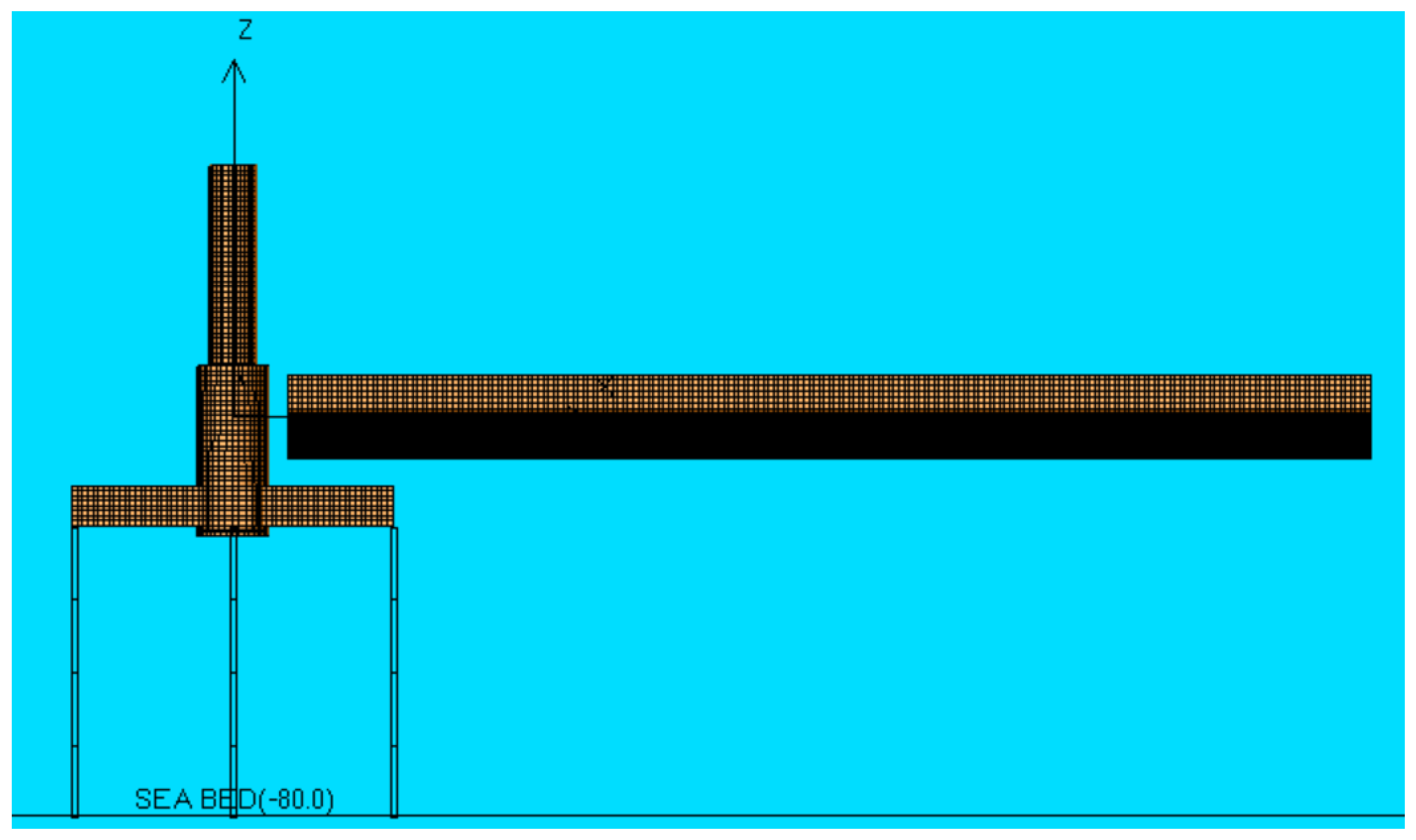
In this study, AQWA code [
19] is employed to develop a numerical hydrodynamic model of the novel tension-leg dual-module offshore wind turbine system and the jack-up crane vessel ORION I. The model is based on potential flow theory, taking into account hydrodynamic coupling effects, as illustrated in
Figure 2.
During the simulation process, the offshore wind turbine jack-up crane vessel is assumed to remain stationary to simplify the analysis and focus on the hydrodynamic interactions between the floating wind turbine system and the surrounding environment.
The motion equation governing the novel tension-leg dual-module floating offshore wind turbine system is expressed as follows:
where
M is the mass matrix;
X is the displacement matrix;
C is the damping matrix;
K is the stiffness matrix;
Fi,wave is the wave load matrix;
Fi,wind is the wind load matrix;
Fi,tlp is the tension-leg load matrix;
Fi,cable is the cable load matrix representing the forces exerted by the cable between the wind turbine tower and the installation vessel;
Fi,fender is the clamping device load matrix, which accounts for the forces between the wind turbine tower and the TLP module. Here,
i = 1, 2 represents the two modules of the tension-leg dual-module floating offshore wind turbine system.
3. Results and Discussion
To evaluate the dynamic response of the system during the wind turbine removal process, simulations were conducted under typical sea conditions. The impact of different positions of the wind turbine installation vessel was analyzed to determine the optimal vessel positioning. To prevent collisions between the wind turbine tower and the TLP module, four pairs of fenders were introduced as buffering devices, and their key parameters were optimized. Additionally, an additional auxiliary sleeve scheme was proposed to effectively reduce the system’s dynamic response. Furthermore, a comparative analysis of the dynamic response during both installation and removal processes was conducted to provide reference guidance for future offshore wind turbine installation and removal.
3.1. Effect of Different Installation Vessel Positions
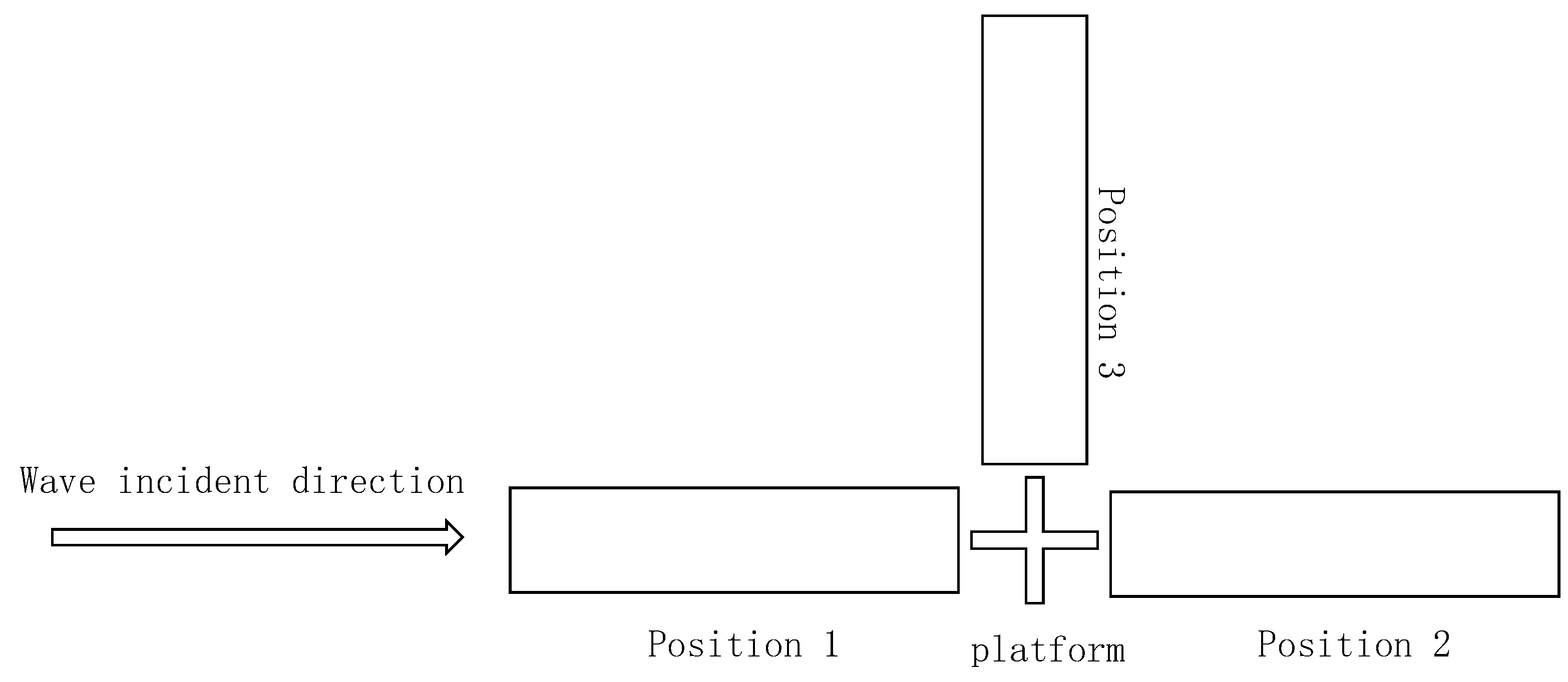
During actual wind turbine installation, the position of the installation vessel can significantly affect the dynamic response of the system. Therefore, three possible installation vessel locations were considered to analyze the possible effect, as shown in
Figure 3. The main results are listed in
Table 3.
In
Table 3, the results indicate that when the installation vessel is located at position 1 (facing incoming waves), the surge is minimal, and the relative motion between the WT module and the TLP module is the smallest. The main reason for this is that the installation vessel acts as a wave shield, reducing wave impact on the system.
Based on the findings, for subsequent removal and installation operations of the WT module, position 1 is recommended as the primary working position to ensure minimal dynamic response and enhanced operational stability.
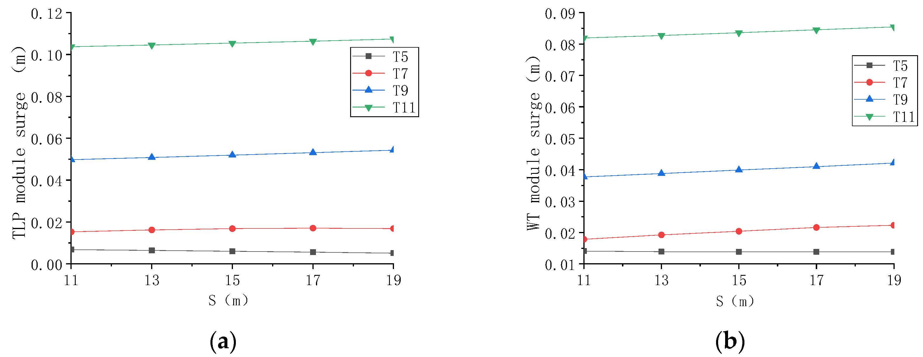
The distance between the installation vessel and the system significantly affects the dynamic response. To analyze this effect, numerical simulations were conducted under regular wave conditions (H = 2 m, T = 5, 7, 9, and 11 s). The minimum distance between the WT module center and the nearest end of the installation vessel was set to S = 11, 13, 15, 17, and 19 m. The dynamic response of the TLP module and WT module at different distances were compared, as shown in
Figure 4.
In
Figure 4, under varying wave periods, the surge of both the TLP module and WT module increases as S increases. Moreover, at larger wave periods, the variation trend of surge with respect to S becomes more pronounced. The effect of wave period variation on the surge is more significant than the effect of S variation.
In addition, it is observed that for the same wave period, the surge of the TLP module and WT module increases progressively as S increases. This suggests that reducing the distance between the system and the installation vessel improves the dynamic response.
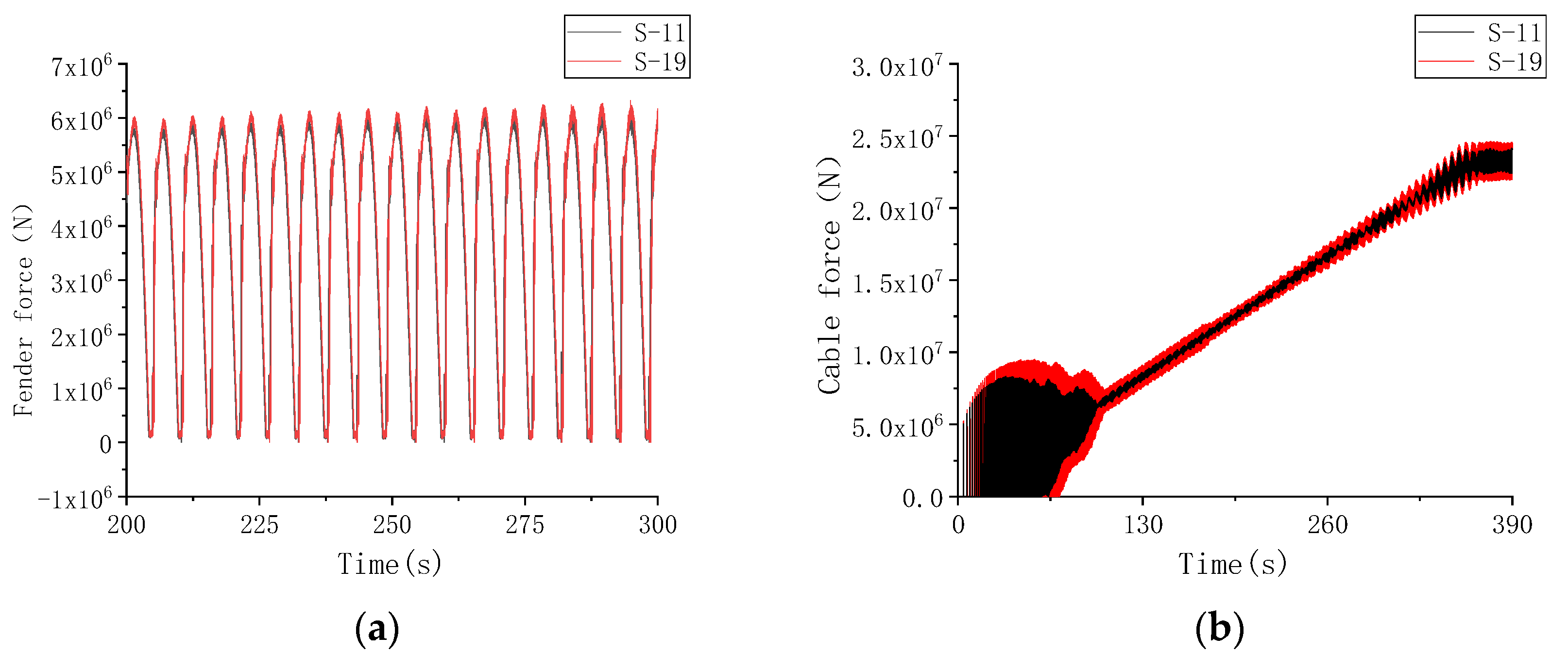
Further analysis was performed by comparing two extreme distances S-11 (s = 11 m) and S-19 (s = 19 m) under typical regular wave condition (H = 2 m, T = 7 s), as shown in
Figure 5. In
Figure 5a, the fender force shows a slight increase with increasing S, but the difference remains within 2%. In
Figure 5b, the cable force exhibits a similar overall trend across different distances. However, as S decreases, the fluctuations in cable force are reduced. Around t = 400 s, a transient fluctuation in the force occurs due to the step change in cable pull-out speed from 0.1 m/s to 0 in AQWA simulations. In practical scenarios, the pull-out speed decreases gradually, which is a limitation that AQWA cannot simulate. Considering the above findings, to optimize the dynamic response while avoiding collisions between the installation vessel and the system it is recommended to minimize the vessel’s distance from the system within safe operational limits.
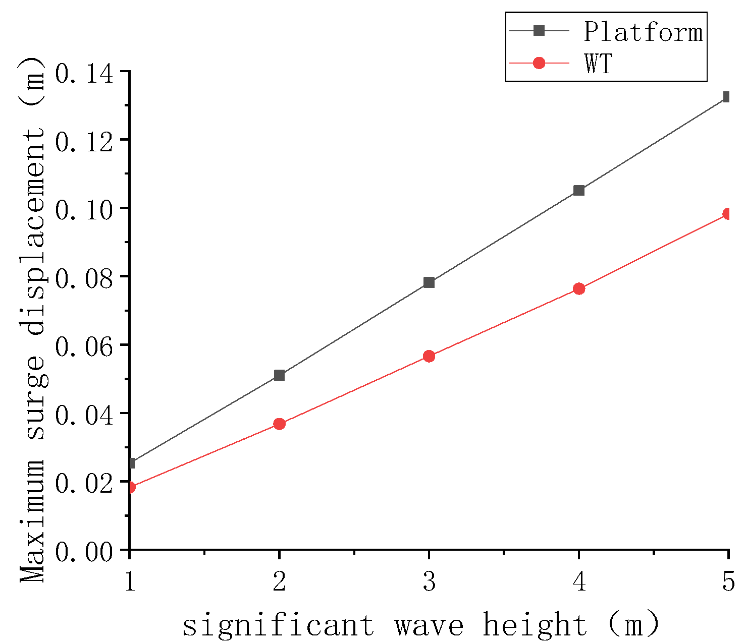
To further analyze the effect of wave height, additional simulations were conducted under regular wave conditions (H = 1, 2, 3, 4, and 5 m, T = 7 s). As shown in
Figure 6, with increasing wave height the maximum surge of both the TLP and WT modules increases proportionally. Additionally, their relative displacement also increases with larger wave heights, indicating that higher waves induce stronger dynamic responses on the system.
3.2. Effect of Fender Parameters
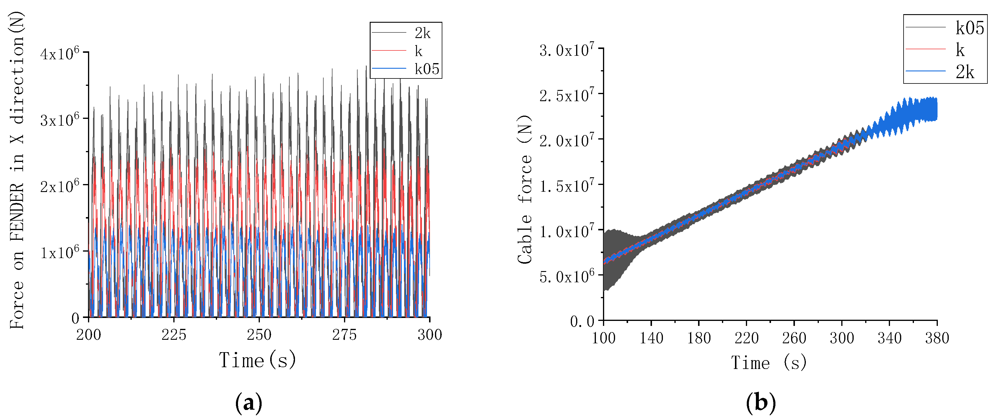
To prevent collisions between the wind turbine tower and the TLP module inner wall during the removal process, two pairs of fenders were installed at 8 m below and 4 m above the water surface to provide buffering effects. The fender parameters include stiffness and size, both of which were analyzed for their effect on the system. Three different stiffness values were considered: k = 5 × 10⁸ N/m (baseline stiffness), k05 = 0.5 × k (half stiffness), 2k = 2 × k (double stiffness).
As shown in
Figure 7a, the fender force increases with increasing stiffness. In this case, lower-stiffness fenders provide a greater buffering effect, reducing excessive force transmission. However, in
Figure 7b, the cable force fluctuates more significantly with lower-stiffness fenders, whereas higher-stiffness fenders result in a more stable cable force profile.
After a comprehensive evaluation of fender force reduction and cable force stability, the middle stiffness value (k = 5 × 10⁸ N/m) was selected for subsequent studies.
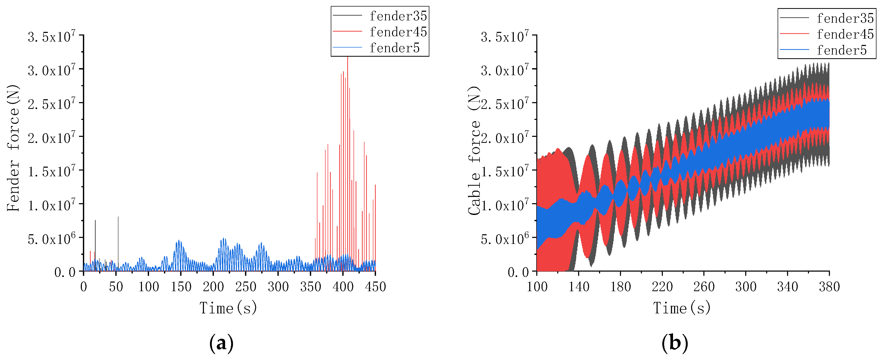
To analyze the effect of fender size, simulations were conducted with a fixed clearance of 0.5 m between the WT module and the TLP module. The main results are shown in
Figure 8. The following three fender sizes were considered: fender35 = 0.35 m, fender45 = 0.45 m, fender5 = 0.5 m.
In
Figure 8a, when the fender size is 0.5 m, the fender force of fender5 is significantly lower compared to fender35 and fender45. Furthermore, the peak fender force is minimized at 0.5 m fender size. In
Figure 8b, when the fender size is 0.5 m, the cable force fluctuations are also reduced.
Based on the above findings, a fender size of 0.5 m is preliminarily recommended as the optimal choice to achieve a balanced dynamic response while minimizing excessive force transmission in the system.
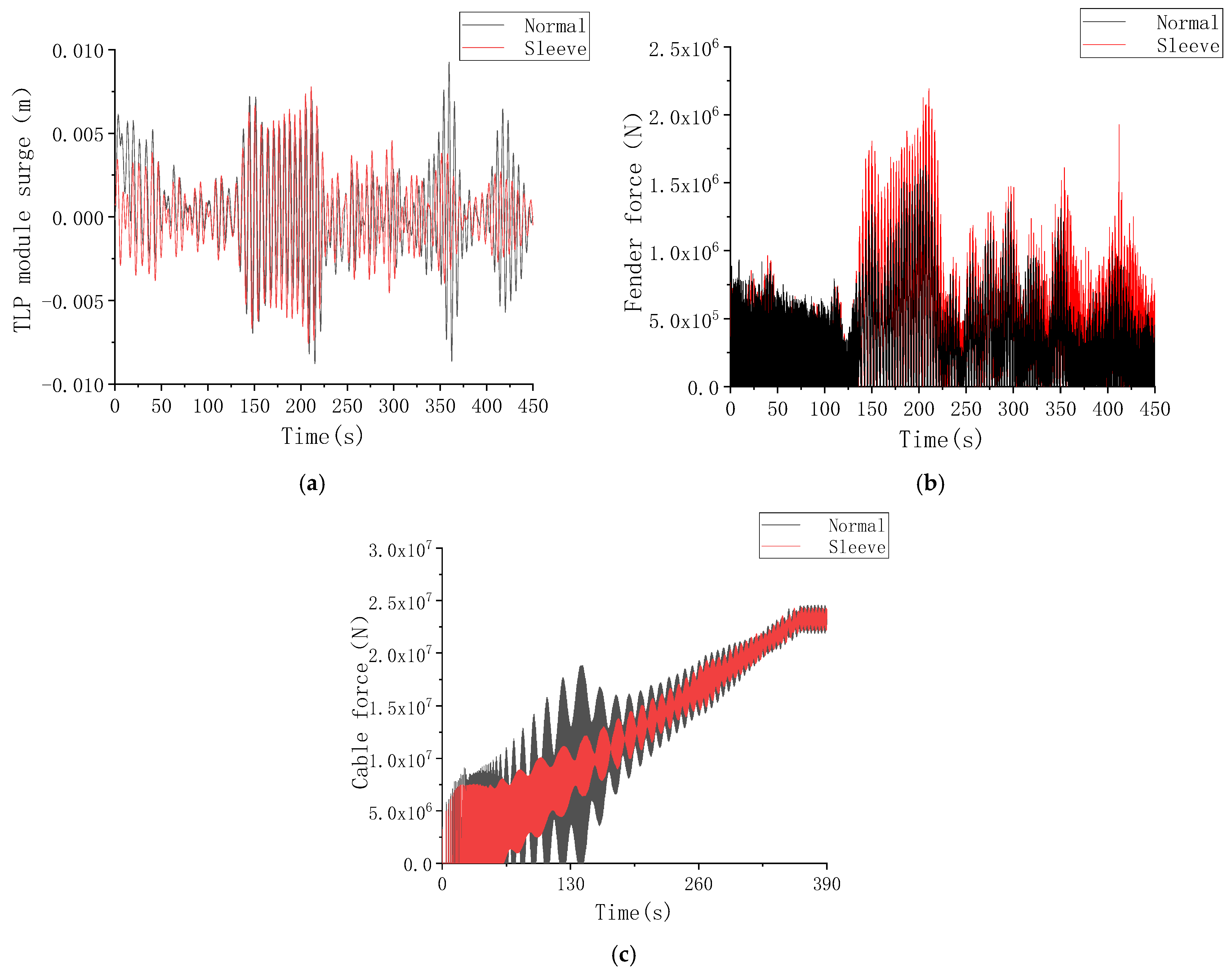
3.3. Additional Auxiliary Sleeve Scheme
To enhance the safety of wind turbine removal, an auxiliary sleeve scheme is proposed, which involves adding a support sleeve at 30 m above the water surface. The inner diameter of the sleeve is designed to have a clearance of 0.5 m from the wind turbine tower.
To prevent collisions between the sleeve and the tower, four fenders are installed inside the sleeve to provide a buffering effect. The detailed auxiliary sleeve design is illustrated in
Figure 9. The preliminary design of the auxiliary sleeve device is like an additional “arm” from the jack-up vessel to limit the motion of the wind turbine module during both the installation and the removal conditions. In the numerical model, the proposed auxiliary sleeve device is simplified as a horizontal constrain.
To evaluate the effectiveness of the auxiliary sleeve, simulations were conducted under typical irregular wave conditions (significant wave height Hs = 2 m; spectral peak period Tp = 7 s), and the dynamic response of the system was compared with and without the sleeve. The results are shown in
Figure 10.
In
Figure 10a, the TLP module surge shows only a slight difference between the two cases, with a maximum variation of approximately 0.002 m. In
Figure 10b, the maximum fender force increases by more than 25% when the sleeve is used, indicating a stronger buffering effect. In
Figure 10c, the cable force is more stable in the sleeve-assisted removal process, which improves overall operational safety and control.
Based on these findings, the additional auxiliary sleeve scheme demonstrates better dynamic response characteristics, making it a safer and more stable option for wind turbine removal operations.
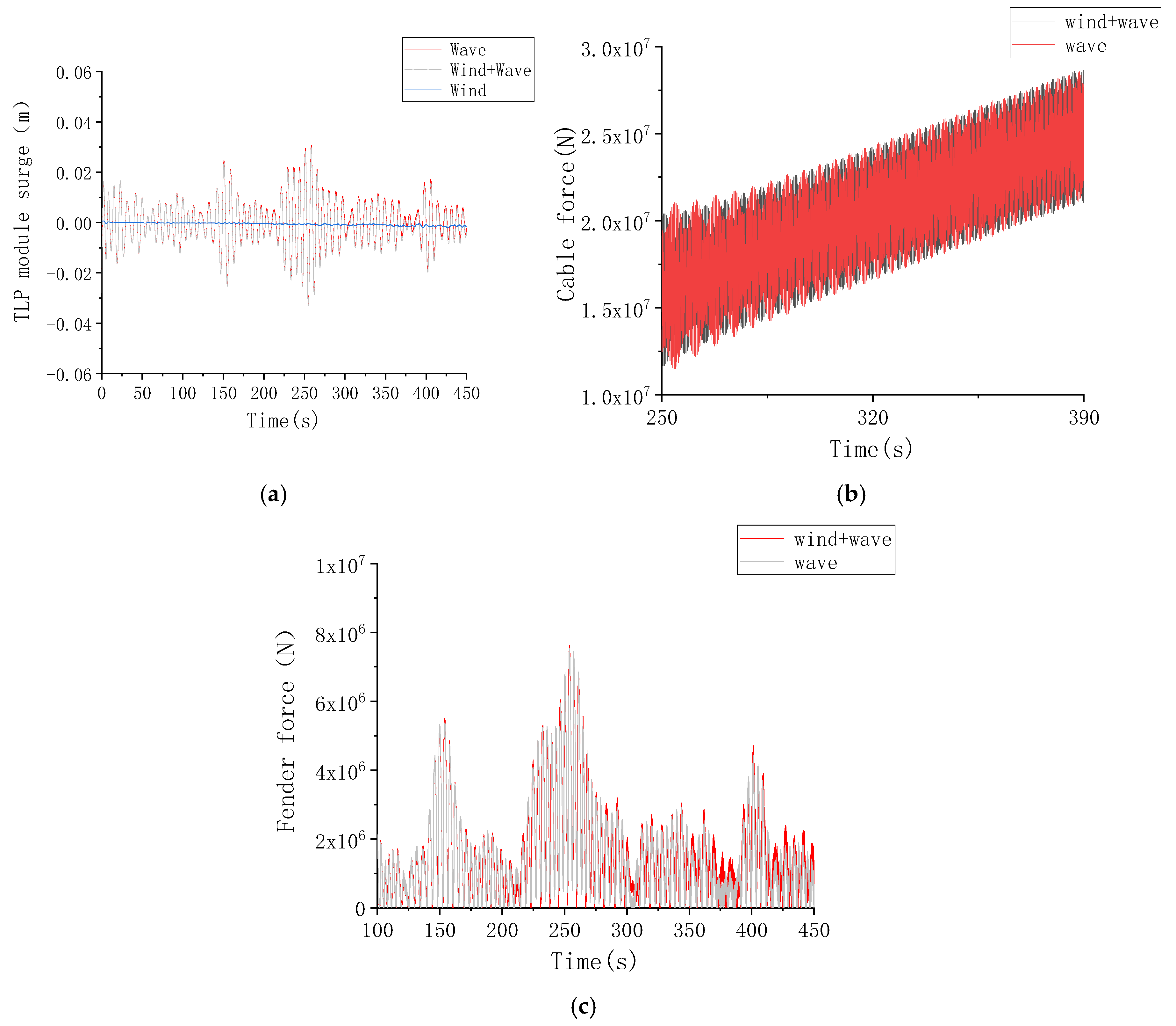
3.4. WT Module Removal Under the Combined Wind and Wave Conditions
To further investigate the dynamic response of the system during wind turbine removal, simulations were conducted under a typical wind–wave combined condition (NPD wind spectrum, average wind speed Va = 15 m/s, significant wave height Hs = 2 m, and spectrum peak period Tp = 7 s, λ = 3.3). Since the wind turbine remains in a shutdown state during removal, the wind load is calculated as
, (where
A is the windward area of the wind turbine,
v is the wind speed,
Cd is the drag coefficient, and
ρ is the air density). The main results are shown in
Figure 11.
In
Figure 11a, the effect of wind load on the TLP module’s surge is minimal, with the extreme surge differing by only 3% compared to wave-only conditions. In
Figure 11b,c, under wind–wave combined conditions, the peak cable force and fender force increase by approximately 5% compared to wave-only conditions. This indicates that wind load has a limited effect on the wind turbine removal process.
The results demonstrate that wave loads dominate the system’s dynamic response, while wind load has a relatively minor effect during the wind turbine removal process.
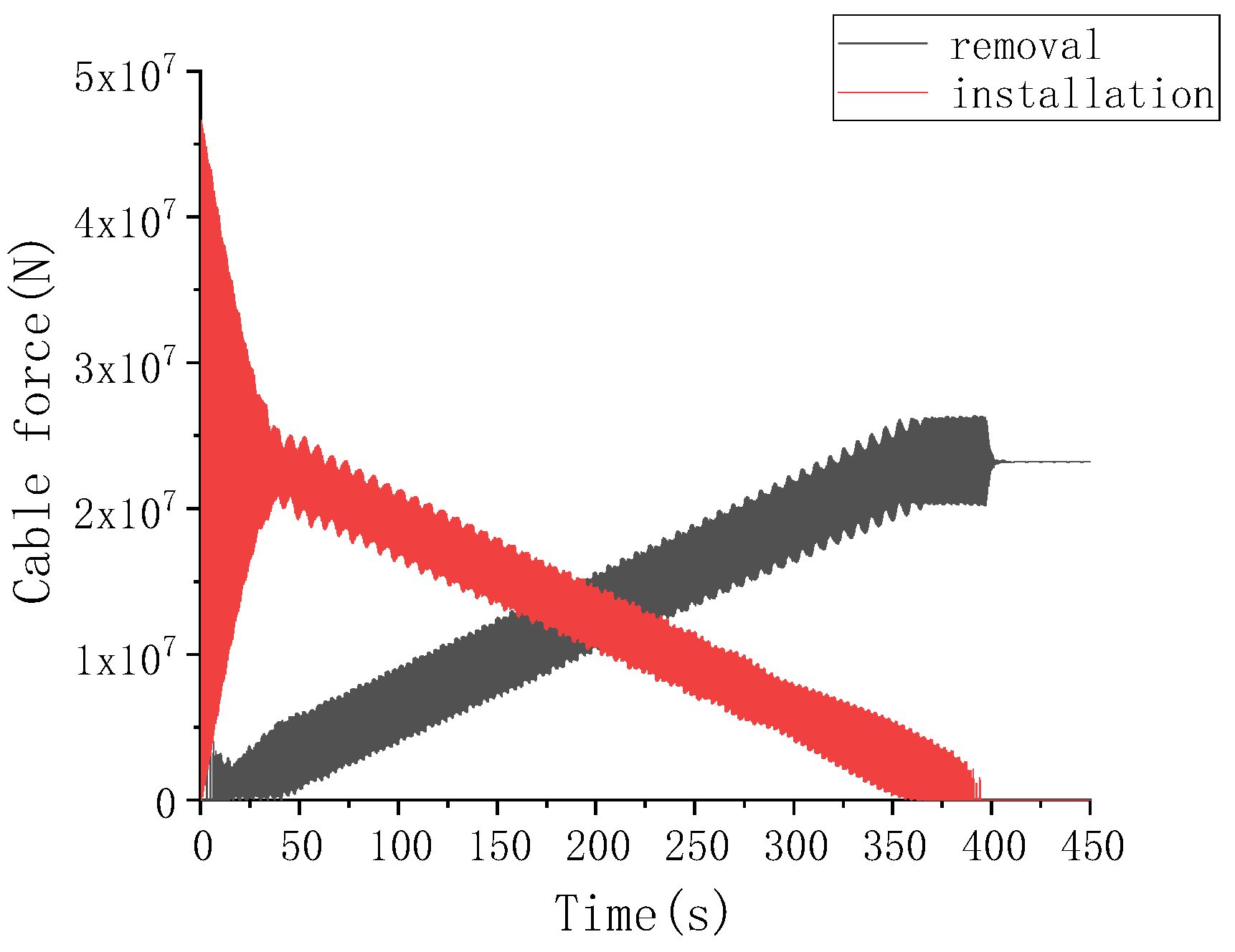
3.5. WT Module Installation Simulation
To analyze the dynamic response of the system during wind turbine installation, simulations were conducted under irregular wave conditions (Hs = 2 m, Tp = 5 s, 7 s, 9 s, 11 s). For the installation process, the inner DTU 10 MW wind turbine module will be gradually put into the outer TLP module by the lifting cable with the assistant of the auxiliary sleeve scheme, until the both the gravity and the displacement of the inner TU 10 MW wind turbine module are equal (as shown in
Figure 9). On the contrary, for the removal process, the inner DTU 10 MW wind turbine module will be gradually pulled out of the outer TLP module by the lifting cable with the assistant of the auxiliary sleeve scheme until the inner DTU 10 MW wind turbine module is totally out of the water.
Figure 12 compares cable forces between installation and removal processes, showing an opposite trend in force variation. Therefore, the primary focus is on the fender force analysis during wind turbine installation.
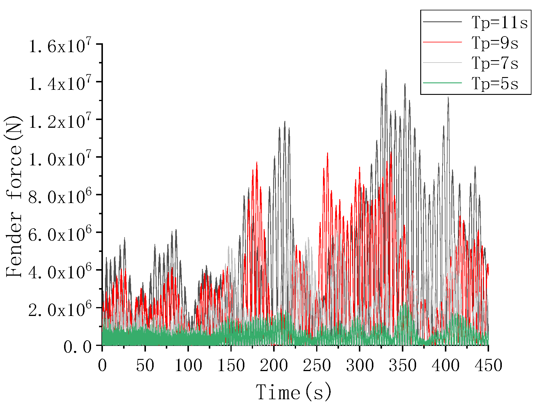
In
Figure 13, the fender force increases with wave period due to its dependence on fender stiffness and relative displacement between the TLP and WT module.
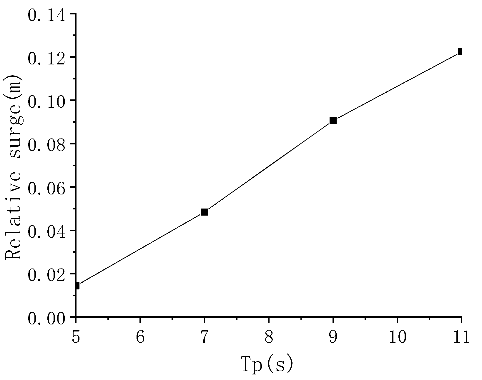
In
Figure 14, the relative surge between the TLP module and WT module grows with increasing wave period. At Tp = 11 s, the peak fender force reaches 1.4 × 10
7 N, indicating high impact forces in long-period waves. To ensure safety, large-period wave conditions should be avoided during installation.
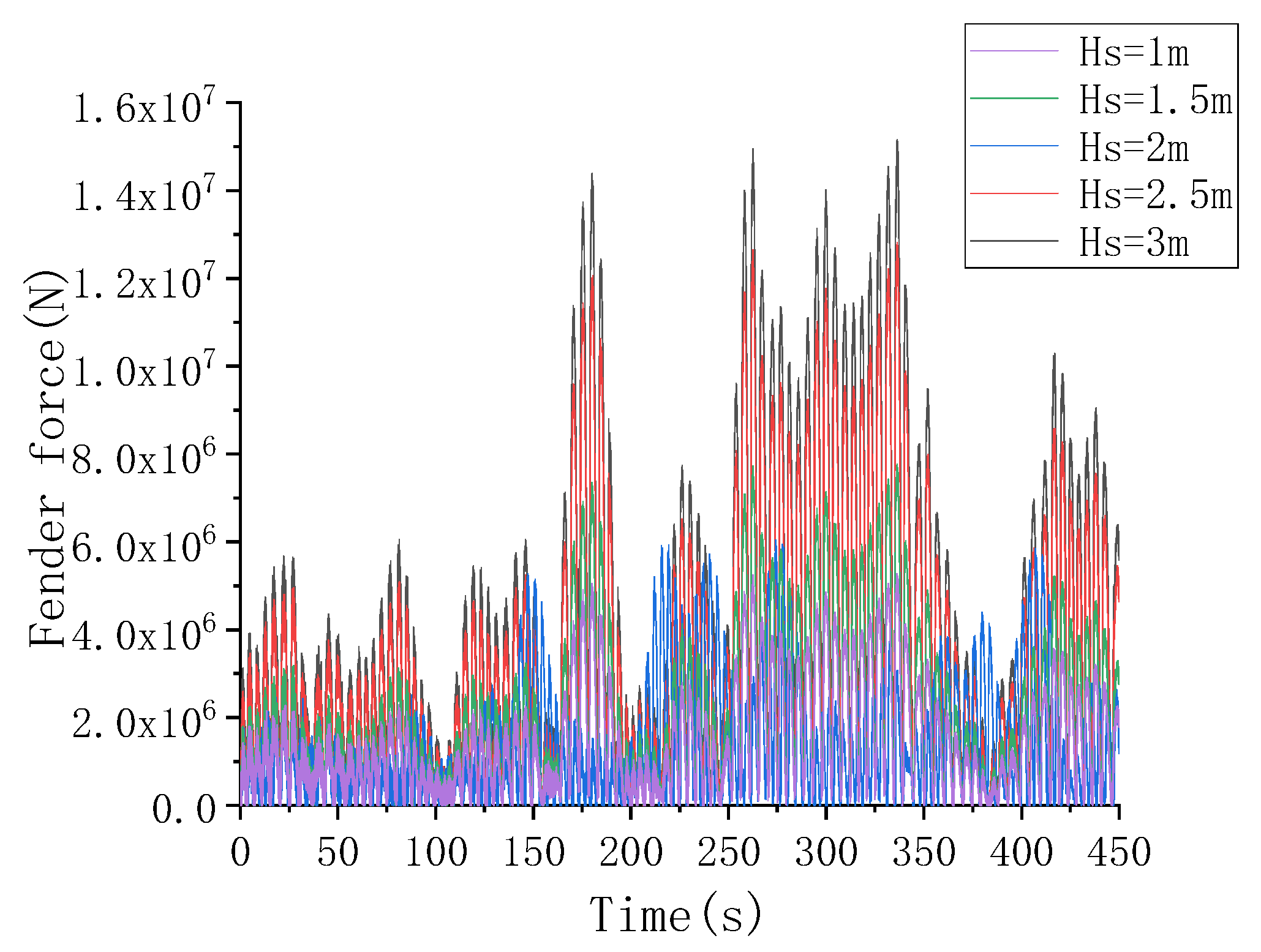
In
Figure 15, additional simulations were performed under irregular wave conditions (Tp = 7 s, Hs = 1, 1.5, 2, 2.5, 3 m). Fender force increases with wave height, and excessive fender force may shorten fender lifespan.
For wind turbine installation, it is crucial to select moderate sea conditions (optimal wave height and wave period) to minimize the fender force and relative displacement, reducing impact forces that could affect the system, and ensuring safe and efficient installation operations. The responses of the fender forces, the cable forces, and the most significant motions (surge) during both installation and removal processes can be used as the input information for the further FEM analysis of the novel dual-module FOWT system. Then, the bending moment and local structure stress information can be obtained for assessing the structural reliability and fatigue safety of the novel system.
In addition, tendons of the novel system are not sensitive to both the installation and the removal process, and all tendons are verified to be safe due to the two special operation sea conditions (Hs < 3 m) being much smaller than the designed extreme sea conditions (usually Hs > 10 m).


