1. Introduction
With sustained global economic development and growing energy demands, the exploitation of strategic resources such as oil and natural gas has progressively shifted from terrestrial and shallow-water environments to more challenging deep-water and high-corrosion conditions [
1,
2,
3]. Bimetallic clad pipes have emerged as effective solutions in offshore oil and gas extraction, combining the structural integrity of carbon steel base pipes with the corrosion resistance of stainless steel or nickel-based alloy liners through advanced metallurgical bonding techniques [
4,
5,
6,
7]. These composite pipes offer superior service life compared to conventional carbon steel pipelines while maintaining cost-effectiveness relative to solid corrosion-resistant alloy pipes [
8].
Two primary categories of bimetallic pipes exist based on interfacial bonding mechanisms: mechanical and metallurgical clad pipes. Metallurgically bonded pipes demonstrate enhanced interfacial strength and load-bearing capacity compared to their mechanically bonded counterparts, making them particularly suitable for marine engineering applications [
9,
10]. However, their complex mechanical behavior and failure mechanisms under operational conditions pose significant challenges to reliability assessment. Although previous studies have made progress in understanding composite pipe behavior, critical knowledge gaps remain regarding the mechanical properties of large-diameter metallurgically clad pipes.
Extensive research has been conducted on mechanically lined pipes through both experimental and numerical approaches. Full-scale tests under axial compression, bending, and reeling loads have been carried out by Hilberink et al. [
11,
12,
13], while Tkaczyk et al. [
14,
15] investigated the evolution of liner buckling during cyclic bending with and without internal pressure. Yuan et al. [
16] performed small-scale four-point bending tests to analyze the effect of local indentation on structural response. Numerical studies by Vasilikis and Karamanos [
17], and Yuan and Kyriakides [
18,
19,
20], explored liner wrinkling and local buckling under bending and axial compression, revealing the influence of geometric imperfections. Further investigations [
21,
22,
23] addressed the effects of internal pressure and tension on structural stability during reeling and combined loading, showing good agreement with experimental observations.
Recent investigations by Yoshitake [
24] employed centrifugal casting to produce metallurgically bonded pipes with uniform wall thickness. Slany et al. [
25] conducted comprehensive analyses of Inconel 625-clad pipes subjected to 0.7D bending deformation. Yang et al. [
26] developed a three-dimensional finite element (FE) model incorporating girth welds to evaluate strain capacity under combined internal pressure and bending moments, identifying the heat-affected zone as a critical failure location. Subsequent research by the same group [
27] investigated cyclic loading effects on welded metallurgical clad pipes, revealing 120% higher strain concentrations in weld regions during installation. Yuan et al. [
28] employed machine learning algorithms to predict collapse pressures of 12-inch mechanically lined pipes, examining the influence of diameter-to-thickness ratios, initial ovality, and material hardening. Overall, prior studies primarily focused on relatively small-diameter pipes (<12 inches), leaving the mechanical behavior of large-diameter clad pipes under deep-sea conditions still poorly understood.
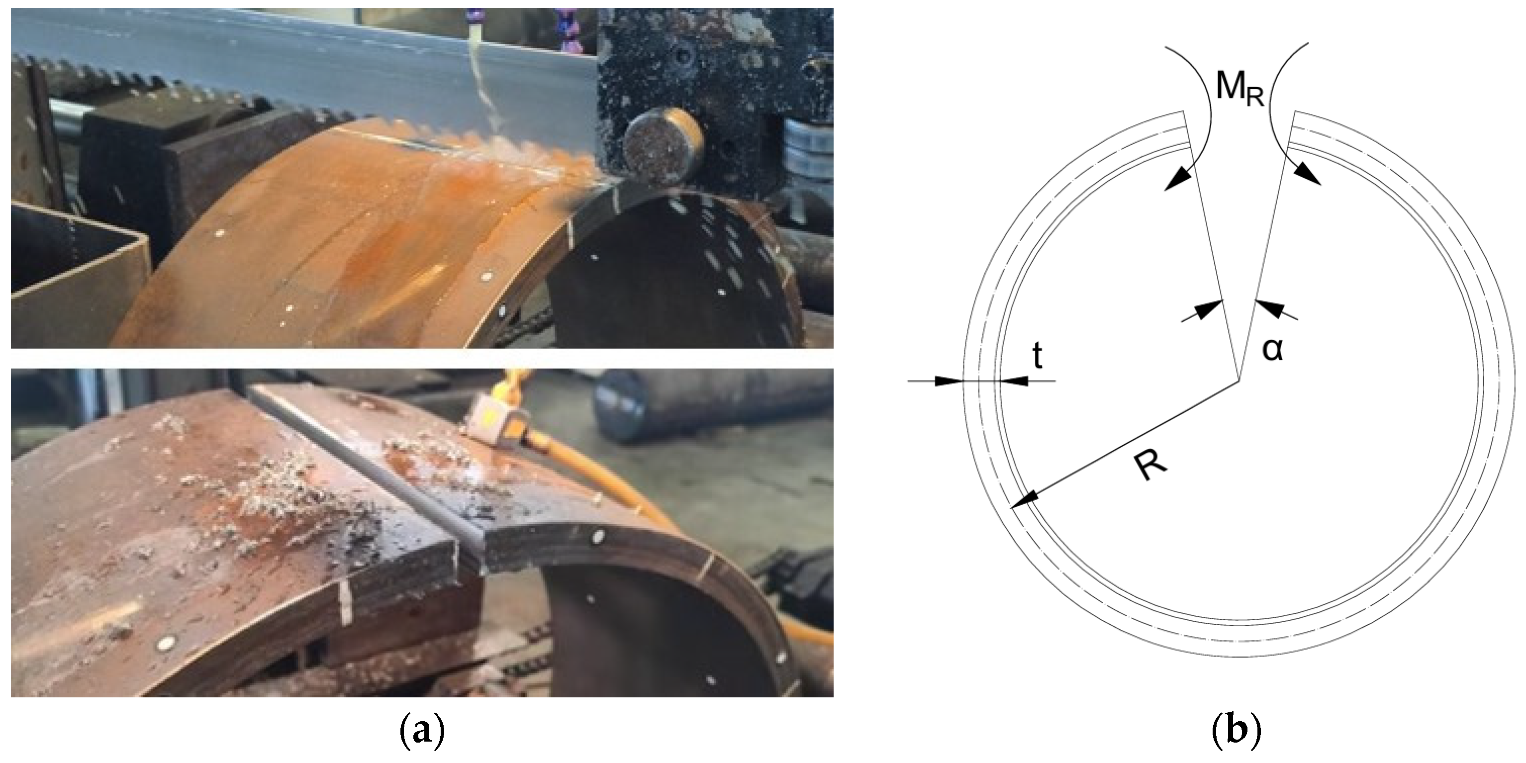
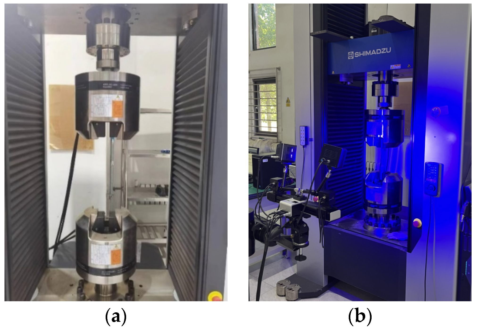
This study focuses on 24-inch X65 + Alloy625 metallurgically clad pipes through experimental characterization and numerical simulation. Unlike most previous studies that concentrate on small-diameter pipes (<12 inches) or simplified boundary conditions, this work investigates large-diameter composite pipes under realistic offshore loading scenarios. The investigation encompasses: (1) geometric characterization via laser scanning and residual stress measurement through the ring-cutting method; (2) uniaxial tensile testing of the base material (X65 steel), clad material (Alloy625), and composite specimens using digital image correlation (DIC) for full-field strain measurement; (3) microstructural analysis through metallography and electron backscatter diffraction (EBSD); and (4) development of a detailed three-dimensional FE model in ABAQUS, incorporating initial ovality and residual stresses to simulate the bending behavior. This comprehensive approach provides new insights into the failure mechanisms and design optimization of large-diameter metallurgical clad pipes in deep-sea environments.
4. Finite Element Analysis
4.1. Model Setup
Bending load represents the most frequent loading condition for subsea pipelines in practical engineering applications. A three-dimensional FE model was developed using ABAQUS 2019 (Dassault Systèmes, Vélizy-Villacoublay, France) commercial software to simulate pipe bending behavior under quasi-static conditions, employing the Static General module.
The FE model replicates a 24-inch metallurgical clad pipe with 609.6 mm outer diameter, 17 mm base layer thickness, 3 mm clad layer thickness, and 1828.8 mm length (equals 3 diameters). Considering dual symmetry characteristics, a quarter model was established with symmetric boundary conditions applied on z = 0 and y = 0 planes (
Figure 12). The model employs C3D8 solid elements for the base pipe and S4 shell elements for the clad layer, with four elements through the base wall thickness and a single-layer shell for the clad. This element configuration is consistent with the modeling strategy adopted by Yuan et al. [
18] in their study on clad pipes, ensuring accurate representation of mechanical behavior while maintaining computational efficiency. Circumferential and axial directions contain 108 and 99 elements, respectively, incorporating graded axial meshing with refined elements at mid-span regions to balance computational efficiency and accuracy.
Experimentally measured material properties were assigned to corresponding inner and outer tubes. In addition, considering the interface delamination takes place at a strain level of 34.17%, the bonding between the two material layers was simulated through tie constraints. Bending moments were applied via reference point rotation coupled with pipe end surfaces. The cross-section at the end plane is free to ovalize while ensuring the plane-remains-plane assumption.
It is worth pointing out that the FE model explicitly incorporates initial ovality of 0.407% and residual stresses of 54.58 MPa from manufacturing processes, utilizing experimentally measured values for both parameters. The residual stress field was introduced via the INITIAL CONDITIONS, TYPE = STRESS option in ABAQUS.
4.2. Bending Simulation
The Mises stress contours of the metallurgically clad pipe before and after bending are presented in
Figure 13a,b. The stress distribution along the axial direction remains uniform during bending deformation, while cross-sectional ovalization becomes evident. The moment-curvature and ovality-curvature curves extracted from the pipe’s symmetric plane are shown in
Figure 14a,b. Specifically, the moment of the base and clad layer, as well as the value of the composite pipe, are plotted, respectively. As expected, the base material layer carries most of the load. To facilitate comparison, the results are presented in dimensionless form. The normalizing variables are based on the parameters of the base pipe as follows:
As demonstrated in
Figure 14a, the bending moment increases linearly with curvature during the elastic stage, followed by a reduced growth rate when plastic yielding occurs. Then, the normalized bending moment reaches its peak value of 1.35 at a normalized curvature of 1.92, followed by a gradual decline. Subsequently, the normalized bending moment gradually decreases with increasing curvature. The normalized curvature at the maximum bending moment is considerably greater than that of mechanically lined pipes [
18], indicating enhanced bending resistance. At the same time, the normalized maximum bending moment is also significantly larger.
Figure 14b reveals progressive ovality accumulation with curvature, where the curve’s increasing slope indicates an accelerated ovalization rate at higher curvatures.
Comparative analyses of pipes with different initial ovalities are shown in
Figure 15 and
Figure 16 to further investigate the mechanical behavior under bending loads. Ovalities of 0%, 0.41%, 0.81%, and 1.22% are assigned to the FE model. As observed,
Figure 15a demonstrates that higher initial ovality reduces the peak bending moment, indicating weakened load-bearing capacity. However, the reduction is approximately 0.5%, which is relatively small and can be considered negligible. In addition,
Figure 15b confirms that initial ovality tends to amplify cross-sectional deformation under identical curvature, which further leads to a reduced moment of inertia and consequent capacity reduction—consistent with findings in
Figure 15a.
The residual stress effects were studied by assigning σ
R/σ
R,0 = {0, 1.0, 2.0, 3.0} to the FE model.
Figure 16a shows negligible variations in peak moments across different residual stress levels, suggesting a limited influence on ultimate bending capacity. Notably, higher residual stresses suppress ovalization growth rates during bending (
Figure 16b), despite identical initial ovality conditions. This interesting phenomenon aligns with Kyriakides’ observations of bending-type residual stress-suppressing effects in single-wall pipes [
30]. The introduction of residual stress initiates reverse ovalization development during bending-induced plasticization, with strain localization concentrating preferentially in the cross-section’s 0° and 180° orientations.
5. Conclusions
This paper investigates the mechanical properties of X65 + Alloy625 metallurgically clad pipes through experimental and numerical methods. Uniaxial tensile tests demonstrate that the base material (X65 steel) and clad material (Alloy625) exhibit excellent coordinated deformation capability. Interface delamination occurs when the average strain reaches 34.17%, followed by sequential fracture of the clad and base layers. Microstructural analysis reveals well-bonded interfaces with X65, which are primarily composed of polygonal ferrite and ferritic bainite, while Alloy625 consists of austenitic equiaxed grains. Finite element simulations indicate that larger initial ovality reduces ultimate bending moment, whereas residual stresses show limited influence on both load-bearing capacity and ovality progression. In this study, the actual measured initial ovality of the pipe was 0.4066%, and the residual stress was 54.58 MPa. The simulation yielded a maximum normalized bending moment of 1.35, corresponding to a normalized curvature of 1.92. These findings can provide some references for the safe design and engineering application of metallurgically clad pipes in deep-sea environments. Future investigations will address the effects of cyclic loading on interface degradation mechanisms. Moreover, subsequent modeling efforts would also integrate weld joint details, enabling a comprehensive assessment of strain localization and failure risks in girth-welded clad pipe systems.


