
Derivation of the Controllable Region for Attitude Control of Towfish and Verification Through Water Tank Test

Abstract
1. Introduction
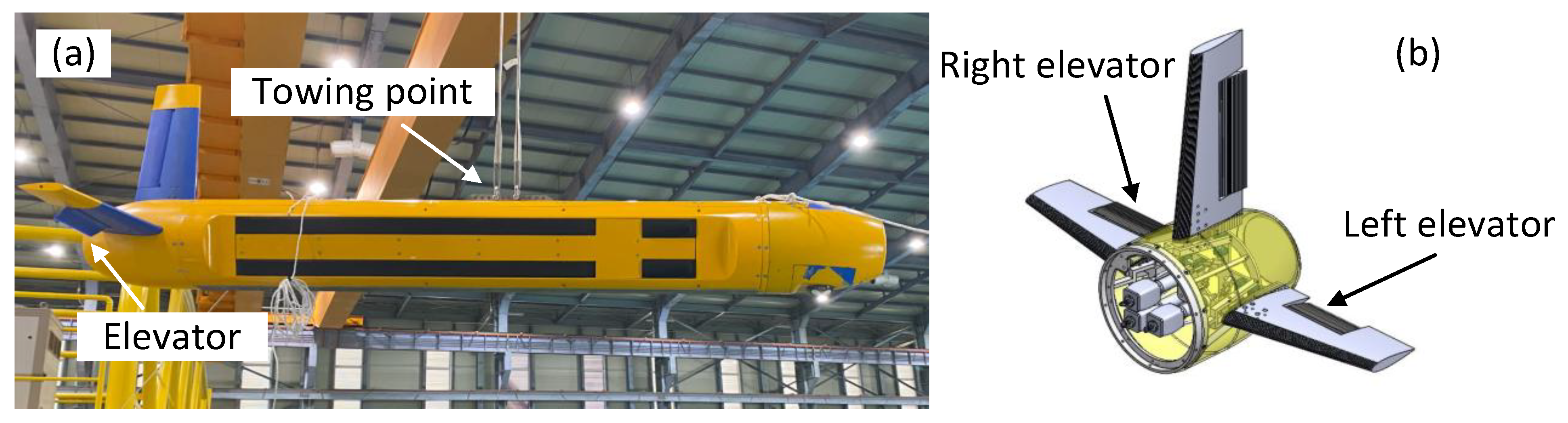
2. Target Towfish and Actuator
3. Dynamic Equations of Motion for the Towfish
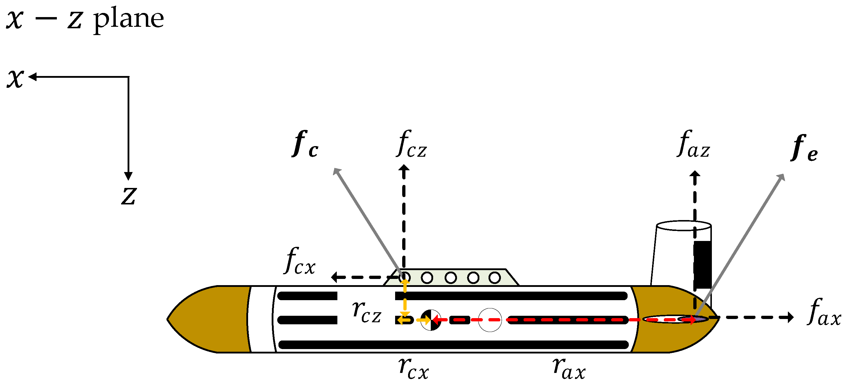
3.1. Coordinate System
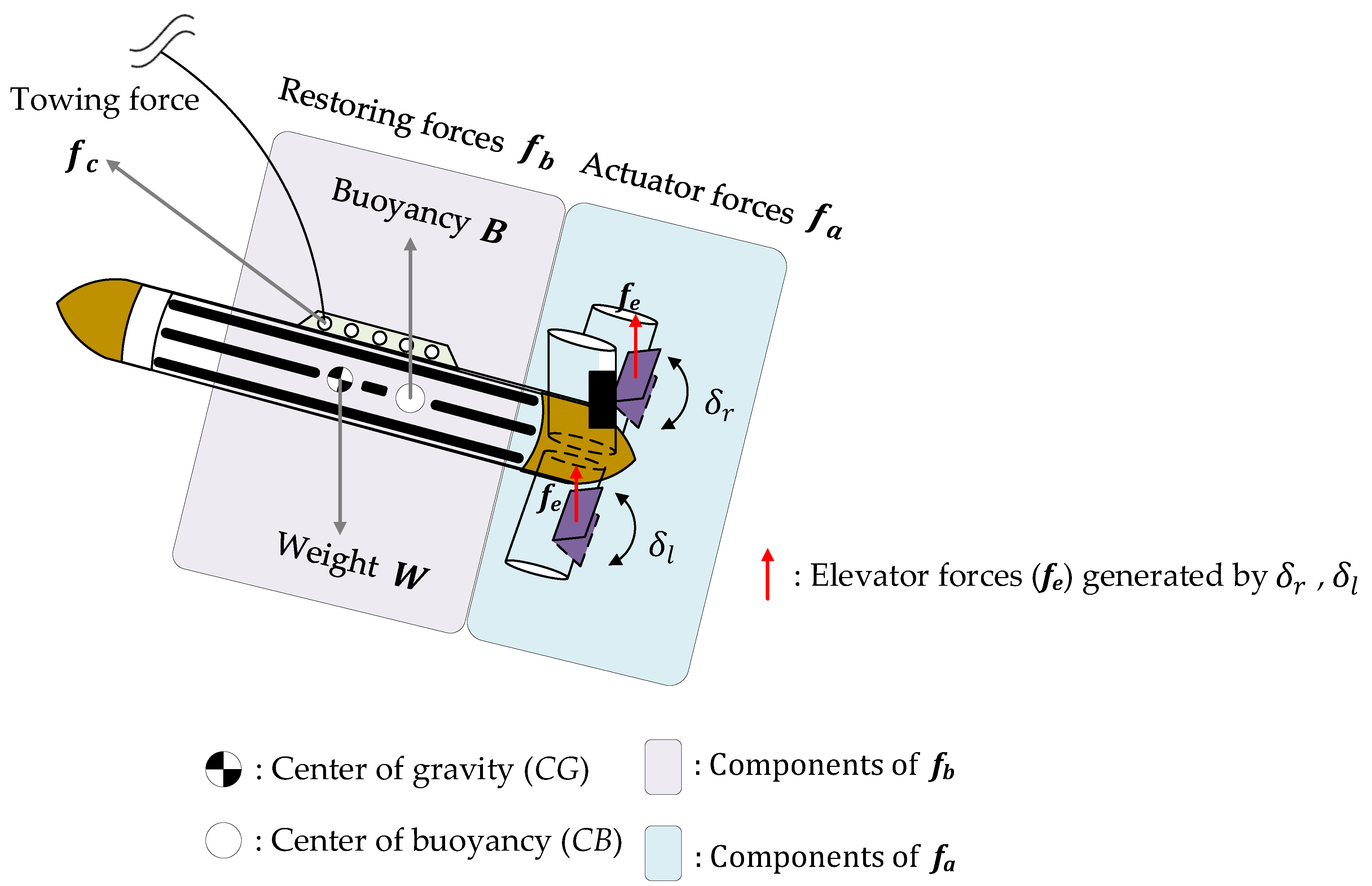
3.2. Forces Affecting the Behavior of Towifsh
3.3. Dynamic Equation of Motion for the Towfish
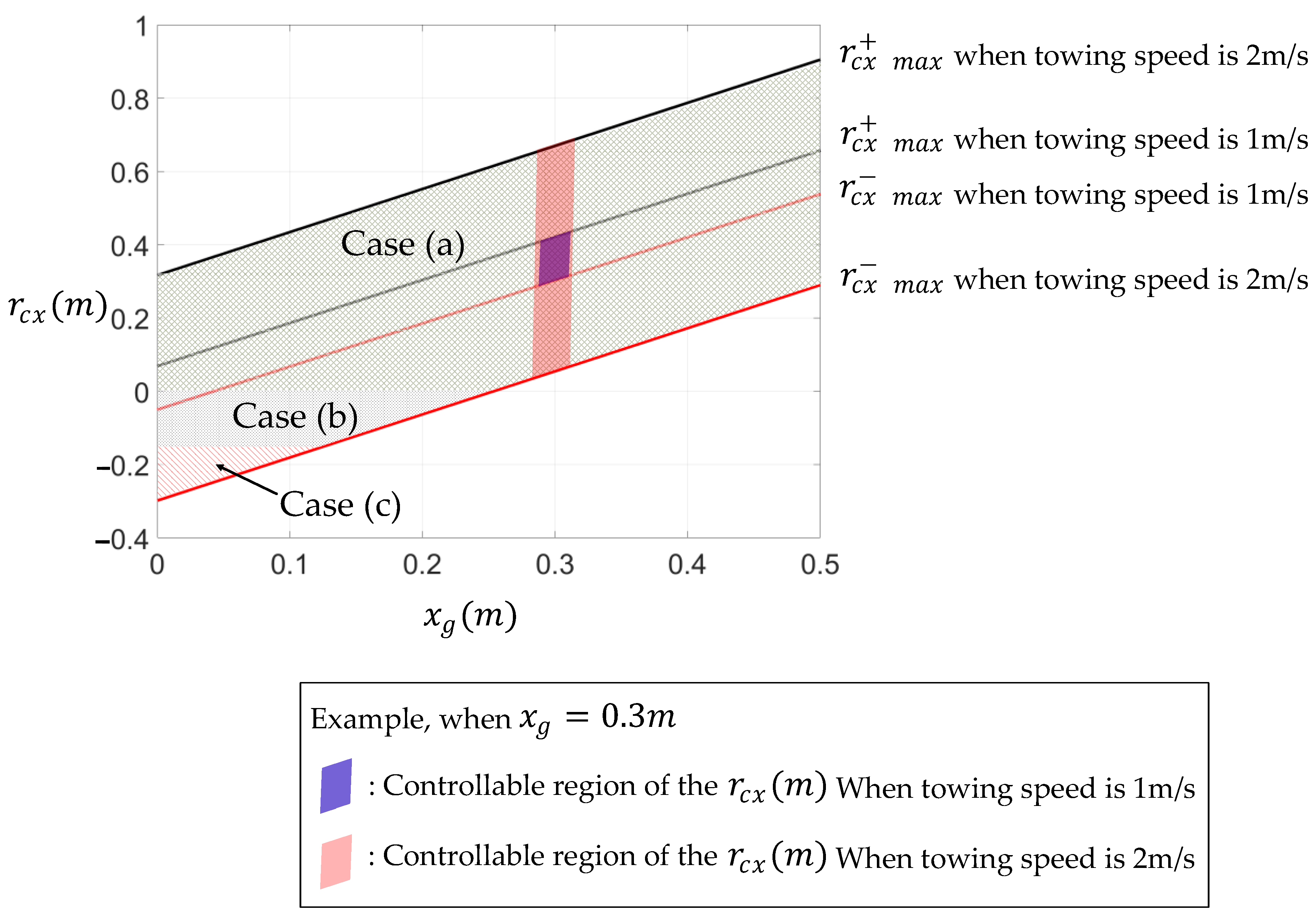
4. Calculation of the Controllable Region for Attitude Control of the Towfish
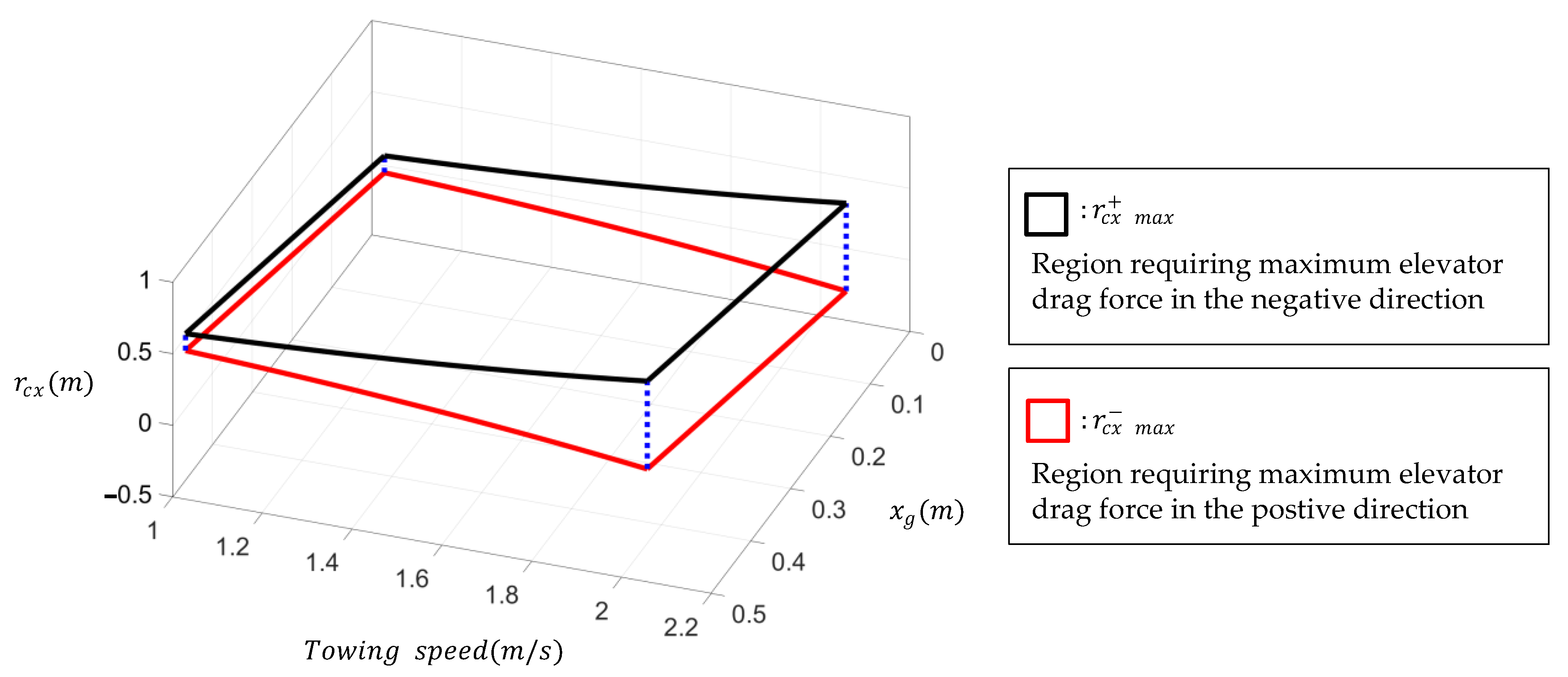
4.1. Controllable Region of the Towing Point That Can Control the Pitch Control
4.2. Simulation
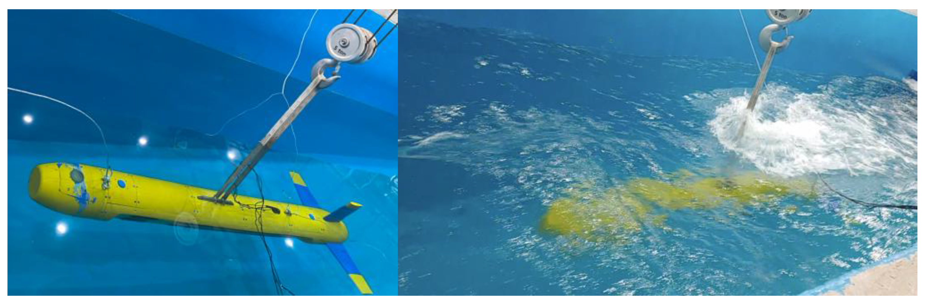
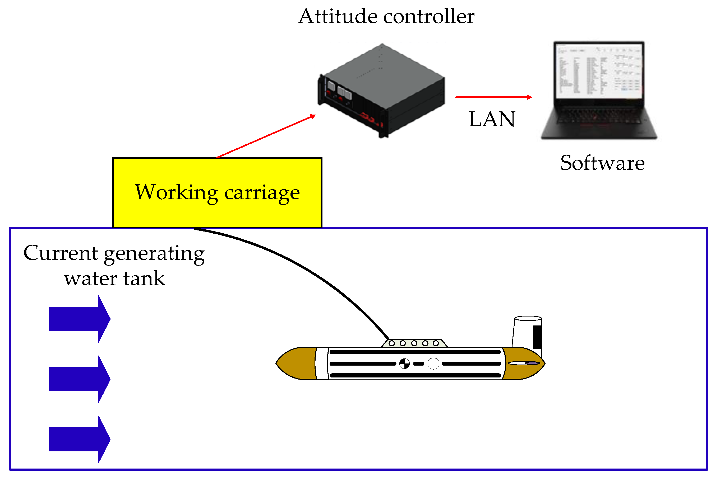
5. Water Tank Test
5.1. Water Tank Test Configuration Diagram
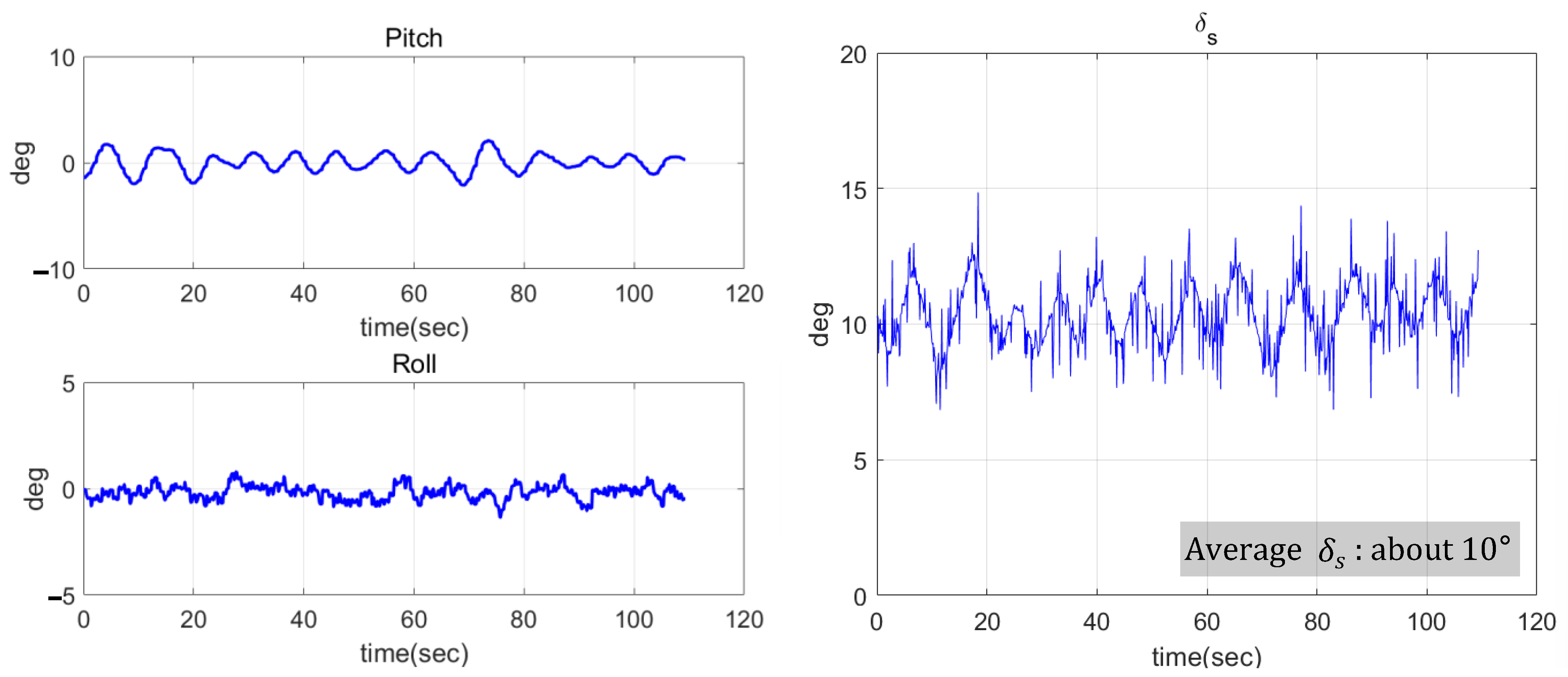
5.2. Water Tank Test at 1 Knot
5.3. Water Tank Test at 3 Knots
5.4. Water Tank Test at 4 Knot
6. Conclusions
Author Contributions
Funding
Data Availability Statement
Conflicts of Interest
Abbreviations
| sonar | Sound navigation ranging |
| InSAS | Interferometric synthetic aperture sonar |
| 6-DOF | Six-degree-of-freedom |
| CFD | Computational fluid dynamics |
| USBL | Ultra-short baseline |
| IMU | Inertial measurement unit |
| NACA | National Advisory Committee for Aeronautics |
References
- Pang, S.K.; Li, Y.H.; Yi, H. Joint formation control with obstacle avoidance of towfish and multiple autonomous underwater vehicles based on graph theory and the null-space-based method. Sensors 2019, 19, 2591. [Google Scholar] [CrossRef] [PubMed]
- Go, G.; Ahn, H.T. Hydrodynamic derivative determination based on CFD and motion simulation for a tow-fish. Appl. Ocean Res. 2018, 82, 191–209. [Google Scholar] [CrossRef]
- Yang, S.; Zhu, X.; Ren, H. Dynamic analysis of a deep-towed seismic system based on a flexible multi-body dynamics frame. Ocean Eng. 2023, 279, 114587. [Google Scholar] [CrossRef]
- Campagnaro, F.; Steinmetz, F.; Renner, B.C. Survey on low-cost underwater sensor networks: From niche applications to everyday use. J. Mar. Sci. Eng. 2023, 11, 125. [Google Scholar] [CrossRef]
- Zhang, C.; Xiao, F. Overview of data acquisition technology in underwater acoustic detection. Procedia Comput. Sci. 2021, 188, 130–136. [Google Scholar] [CrossRef]
- Neupane, D.; Seok, J. A review on deep learning-based approaches for automatic sonar target recognition. Electronics 2020, 9, 1972. [Google Scholar] [CrossRef]
- Lee, J.; Oh, Y.; Park, S.; Kim, H. Development of towed synthetic aperture sonar system. Korea Soc. Nav. Sci. Technol. 2019, 2, 28–31. [Google Scholar] [CrossRef]
- Hansen, R.E.; Saebo, T.O.; Gade, K.; Chapman, S. Signal processing for AUV based interferometric synthetic aperture sonar. In Proceedings of the OCEANS 2003, San Diego, CA, USA, 22–26 September 2003. [Google Scholar]
- Teixeira, F.C.; Aguiar, A.P.; Pascoal, A. Nonlinear adaptive control of an underwater towed vehicle. Ocean Eng. 2010, 37, 1193–1220. [Google Scholar] [CrossRef]
- Cammarata, A.; Sinatra, R. Parametric study for the steady-state equilibrium of a towfish. J. Intell. Robot. Syst. 2015, 81, 231–240. [Google Scholar] [CrossRef]
- Droppers, J.C.; Fisher, W.; Predmyrskyy, A. Tow-body control system modeling and tuning on a real-world vehicle. In Proceedings of the OCEANS 2023, Limerick, Ireland, 5–8 June 2023. [Google Scholar]
- Muscat, M.; Cammarate, A.; Maddio, P.D.; Sinatra, S. Design and development of a towfish to monitoe marine pollution. Euro-Mediterr. J. Environ. Integr. 2018, 3, 11. [Google Scholar] [CrossRef]
- Park, J.; Kim, N. Dynamics modeling of a semi-submersible autonomous underwater vehicle with a towfish towed by a cable. Int. J. Nav. Archit. Ocean Eng. 2015, 7, 409–425. [Google Scholar] [CrossRef]
- Artur, G.; Andrzej, F.; Mariusz, W. Ecperience with the use of a rigidly-mounted side-scan sonar in a harbor basin bottom investigation. Ocean Eng. 2015, 109, 439–443. [Google Scholar] [CrossRef]
- Lambert, C.; Nahon, M.; Buckham, B.; Seto, M. Dynamics and control of towed underwater vehicle system, part II: Model validation and turn maneuver optimization. Ocean Eng. 2003, 30, 471–485. [Google Scholar] [CrossRef]
- Buckham, B.; Nahon, M.; Seto, M.; Zhao, X.; Lambert, C. Dynamics and control of towed underwater vehicle system, part I: Model development. Ocean Eng. 2003, 30, 453–470. [Google Scholar] [CrossRef]
- Seto, M.T.; Watt, G.D.; Hopkin, D. A fully interactive dynamic simulation of a semi-submersible towing a large towfish. In Proceedings of the OCEANS 99, Seattle, WA, USA, 13–16 September 1999. [Google Scholar]
- Koterayama, W.; Kyozukw, Y.; Nakamura, M.; Ohkusu, M.; Kashiwagi, M. The motion of a depth controllable towed vehicle. Offshore Mech. Artic Eng. 1998, 1, 423–430. [Google Scholar]
- Kim, J. Adaptive Coverage Path planning for underwater sonar scans in environments with changing current. J. Mar. Sci. Eng. 2025, 13, 118. [Google Scholar] [CrossRef]
- Yang, S.; Ren, H.; Zhu, X. Dynamic modeling of cable deployment/retrieval based on ALE-ANCF and adaptive step-size integrator. Ocean Eng. 2014, 309, 2. [Google Scholar] [CrossRef]
- Go, G.; Lee, E.; Ahn, H.T.; Chun, S.Y. 6DOF simulation and determination of hydrodynamic derivatives of underwater tow-fish using CFD. J. Soc. Nav. Archit. Korea 2016, 53, 315–328. [Google Scholar] [CrossRef]
- Kim, M.K.; Park, D.J.; Kim, J.H.; Choi, J.K. Feasuble positions of towing point and center of gravity for towfish attitude control. J. Ocean Eng. Technol. 2020, 34, 334–341. [Google Scholar] [CrossRef]
- Kim, M.K.; Park, D.J.; Oh, Y.S.; Kim, J.H.; Choi, J.K. Towfish Attitude Control: A Consideration of Towing Point, Center of Gravity, and Towing Speed. J. Mar. Sci. Eng. 2021, 6, 641. [Google Scholar] [CrossRef]
- Holger, K. Track Control of a Towed Underwater Sensor Carrier. IFAC Proceeding Vol. 2000, 33, 89–94. [Google Scholar]
- Fossen, T.I. Handbook of Marine Craft Hydrodynamics and Motion Control; John Willy & Sons Ltd.: Sussex, UK, 2011. [Google Scholar]
- Fossen, T.I. Marine Control Systems; Marine Cybernetics: Trondheim, Norway, 2001. [Google Scholar]
- Fossen, T.I. Guidance and Control of Ocean Vehicles; John Willy & Sons Ltd.: Sussex, UK, 1994. [Google Scholar]
- Park, C.; Shin, M.; Choi, J.; Hwang, H.; Shin, Y.; Kim, Y. An experimental study on effect of angle of attack on elevator control force for underwater vehicle with separate fixed fins. Ocean Eng. Technol. 2016, 30, 243–252. [Google Scholar] [CrossRef]


| Towfish | |||
|---|---|---|---|
| Length | 3.5 m | Weight in air | 2940 N |
| Diameter | 0.4 m | Buoyancy | 490 N |
| Towing speed | 2 m/s | Towing speed | 2 m/s |
| Single elevator area | 0.025 m2 | ||
| Sensor (Manufacturer/Model) | Performance | ||
| IMU (Advanced Navigation/Spatial FOG Dual) | pitch, roll and heading 0.05°/HR FOG Gyro | ||
| USBL (Advanced Navigation/Subsonus) | 0.1 m position accuracy 1000 m depth and range | ||
| Hydrodynamic Derivatives | Values | Hydrodynamic Derivatives | Values |
|---|---|---|---|
| 300 kg | |||
Disclaimer/Publisher’s Note: The statements, opinions and data contained in all publications are solely those of the individual author(s) and contributor(s) and not of MDPI and/or the editor(s). MDPI and/or the editor(s) disclaim responsibility for any injury to people or property resulting from any ideas, methods, instructions or products referred to in the content. |
© 2025 by the authors. Licensee MDPI, Basel, Switzerland. This article is an open access article distributed under the terms and conditions of the Creative Commons Attribution (CC BY) license (https://creativecommons.org/licenses/by/4.0/).
Share and Cite
Lee, J.; Kim, M.-K. Derivation of the Controllable Region for Attitude Control of Towfish and Verification Through Water Tank Test. J. Mar. Sci. Eng. 2025, 13, 834. https://doi.org/10.3390/jmse13050834
Lee J, Kim M-K. Derivation of the Controllable Region for Attitude Control of Towfish and Verification Through Water Tank Test. Journal of Marine Science and Engineering. 2025; 13(5):834. https://doi.org/10.3390/jmse13050834
Chicago/Turabian StyleLee, Jihyeong, and Min-Kyu Kim. 2025. "Derivation of the Controllable Region for Attitude Control of Towfish and Verification Through Water Tank Test" Journal of Marine Science and Engineering 13, no. 5: 834. https://doi.org/10.3390/jmse13050834
APA StyleLee, J., & Kim, M.-K. (2025). Derivation of the Controllable Region for Attitude Control of Towfish and Verification Through Water Tank Test. Journal of Marine Science and Engineering, 13(5), 834. https://doi.org/10.3390/jmse13050834