Article

Design of Portable Reefs to Protect Young Mangroves

1
School of Environment and Society, Institute of Science Tokyo, Tokyo 152-8550, Japan
2
Technical Research Institute, Fudo Tetra Corporation, Tsuchiura 300-0006, Japan
*
Author to whom correspondence should be addressed.
J. Mar. Sci. Eng. 2025, 13(4), 734; https://doi.org/10.3390/jmse13040734
Submission received: 8 February 2025 / Revised: 30 March 2025 / Accepted: 2 April 2025 / Published: 6 April 2025

Abstract

:
For a successful mangrove plantation, previous studies have proposed a small rubble mound breakwater, termed a “portable reef”, and explored the effectiveness of such reefs in terms of wave transmission. This study conducted a real-scale wave flume experiment incorporating a portable reef to assess the oscillatory behavior of young mangroves. To capture the dynamics of these young mangrove analogs—represented as elastic bodies—we employed a high-speed camera for precise tracking. A comparative analysis of the oscillatory characteristics was performed, evaluating the responses in both the presence and absence of the reef. The findings revealed several important points. First, portable reefs can effectively reduce wave heights, but they reduce plant oscillations to an even greater degree. Second, by calibrating the elastic modulus of the plant models, their oscillation behaviors can be analytically predicted. The results of our analytical model indicate that the acceleration experienced by the plants is amplified under conditions of shorter wave periods and softer stems, highlighting an increased susceptibility to damage from short-period waves, particularly in very young mangroves. Third, we identified that the conventional wave transmission formulas tend to overestimate the reduction in wave energy attributable to portable reefs, which consequently leads to an underestimation of the young mangroves’ oscillations. Based on these findings, we propose an integrated chart that combines wave transmission and plant oscillation coefficients, aimed at enhancing the design and effectiveness of portable reefs in protecting young mangroves. The insights obtained from this study will aid in the informed design of portable reefs.

1. Introduction

In numerous countries, mangrove plantation initiatives have been launched in response to the alarming decline of mangrove forests. In recent years, there has been increasing recognition of the potential for carbon sequestration to establish mangrove plantations, positioning them as key components within blue carbon ecosystems. Despite these initiatives, many plantation efforts have not necessarily achieved their intended goals [1,2]. For example, in the Philippines, despite significant financial investments in mangrove forest plantations, the long-term survival rate of these mangroves remains dismally low, standing at only 10–20% [3]. Similarly, the success rates of reforestation programs exhibit considerable variability, ranging from 25% in Vietnam to between 0% and 78% in Sri Lanka [4,5]. In a mangrove replantation initiative in Malaysia, the water level was too deep and the sediment deposition was insufficient, resulting in areas with low success rates in terms of afforestation [6]. Devaney et al. (2021) [7] evaluated the effect of soil salinity on the initial establishment of a mangrove plantation in the Saloum delta of Senegal, and found that the mangrove seedling survival after 1 to 3 years was reduced due to the high salinity. Mangrove growth is dependent on tidal currents and the sediment they bring. However, these basic ecological principles are ignored in many mangrove rehabilitation and restoration programs [8].
A significant factor contributing to this lack of success may be the reliance on a trial-and-error approach in implementing mangrove plantations owing to an insufficient scientific understanding of the challenges involved [6,9]. Furthermore, to mask their failure, stakeholders often report misleading metrics of “success” that focus on the area of land planted rather than the crucial long-term survival rates of the mangroves themselves [10]. Consequently, an overemphasis on the sheer number of planted trees may hinder a true assessment of the effectiveness and overall success of these plantation efforts. Science-based approaches are required to increase the success rate of mangrove plantations and promote natural regeneration [2,11,12].
Young mangrove ecosystems, which include diverse species such as barnacles and crabs, are particularly susceptible to a range of environmental threats, such as intense wave action, unfavorable soil conditions, plastic pollution, and herbivory [5,13,14]. In large-scale mangrove plantation projects, seedlings are usually nurtured in nurseries for several months before being transplanted into plantation sites, often in plastic pots. This method helps to minimize damage from adverse environmental conditions. Conversely, the direct planting of propagules along coastlines is relatively uncommon due to the heightened risk of being dislodged by waves. Despite this, direct planting is inherently less complex than the transplantation of potted seedlings. Based on the growing apprehension regarding the contribution of plastic bags to marine pollution [15,16], direct planting has emerged as a more sustainable alternative.
In direct planting, certain wave dissipation strategies need to be implemented during the establishment phase of young mangroves, as they require time to develop resilient root systems. The practical effectiveness of breakwaters in protecting mangrove plantations has been observed in various locations, particularly in Indonesia, Vietnam, and Thailand [17,18]. Nonetheless, the installation of permanent civil engineering breakwaters may impede the gradual expansion of planted areas or inadvertently cause coastal erosion in surrounding regions. Therefore, simple community-based measures that are easy to demolish or relocate are desirable [18]. Several initiatives have been undertaken to protect mangrove plantation sites on eroded coastlines, notably through the deployment of wooden piles and fences in areas such as the Mekong Delta of Vietnam and Demak in Indonesia [19,20,21]. However, wooden piles for coastal protection are not always environmentally friendly, because they are less durable and easily damaged; further, the debris can affect mangrove tree stems and the surrounding coastal ecosystem [22,23]. Therefore, there is a need for mangrove plantation conservation measures that are simple to install while possessing a certain degree of durability.
As an innovative approach for coastal protection, community-based portable reefs are compact and relocatable rubble mound breakwaters with a cross-sectional area of ~1 m2. This approach was thoroughly examined by Sreeranga et al. [11,24,25], whose findings revealed that such small reefs can significantly diminish wave transmission. Thus, even a modest permeable structure can effectively serve as a rudimentary breakwater, offering vital protection for young mangroves. However, Takagi et al. [12] highlighted a critical issue, in that young mangroves experience pronounced oscillations due to short-period waves, even when the wave heights are minimal. This phenomenon arises from the resonance that occurs between the waves and the inherent elasticity of mangrove stems. Strong oscillations pose a significant risk to the delicate leaves and stems of these vulnerable plants. Therefore, community-based coastal protection strategies should prioritize mitigating these oscillations in young mangrove plants, rather than focusing exclusively on wave energy dissipation.
This study not only emphasizes the importance of addressing wave transmission but also calls for a re-evaluation of the design considerations for portable reefs. Specifically, there is a need to focus on the oscillatory dynamics experienced by plants situated behind the reef, ensuring that protective measures are comprehensive and effective in promoting the resilience of young mangroves. To identify the critical design factors, a real-scale wave flume experiment is conducted by embedding an elastic body mimicking a real young mangrove into the flume bed, and the oscillatory characteristics of plants with and without a portable reef are carefully analyzed based on both experimental and analytical methods. This study examines the relevance of established wave transmission formulas in the context of portable reef designs. Furthermore, we propose a novel wave transmission chart specifically tailored for the design of portable reefs aimed at safeguarding young mangroves. Note that in ordinary civil engineering practice, the term “low-crested breakwater” might be used in the context of a compact wave-dissipating structure. In this study, however, the emphasis is on the small size and portability, and therefore, the term “portable reef” is used hereafter.

2. Methodology

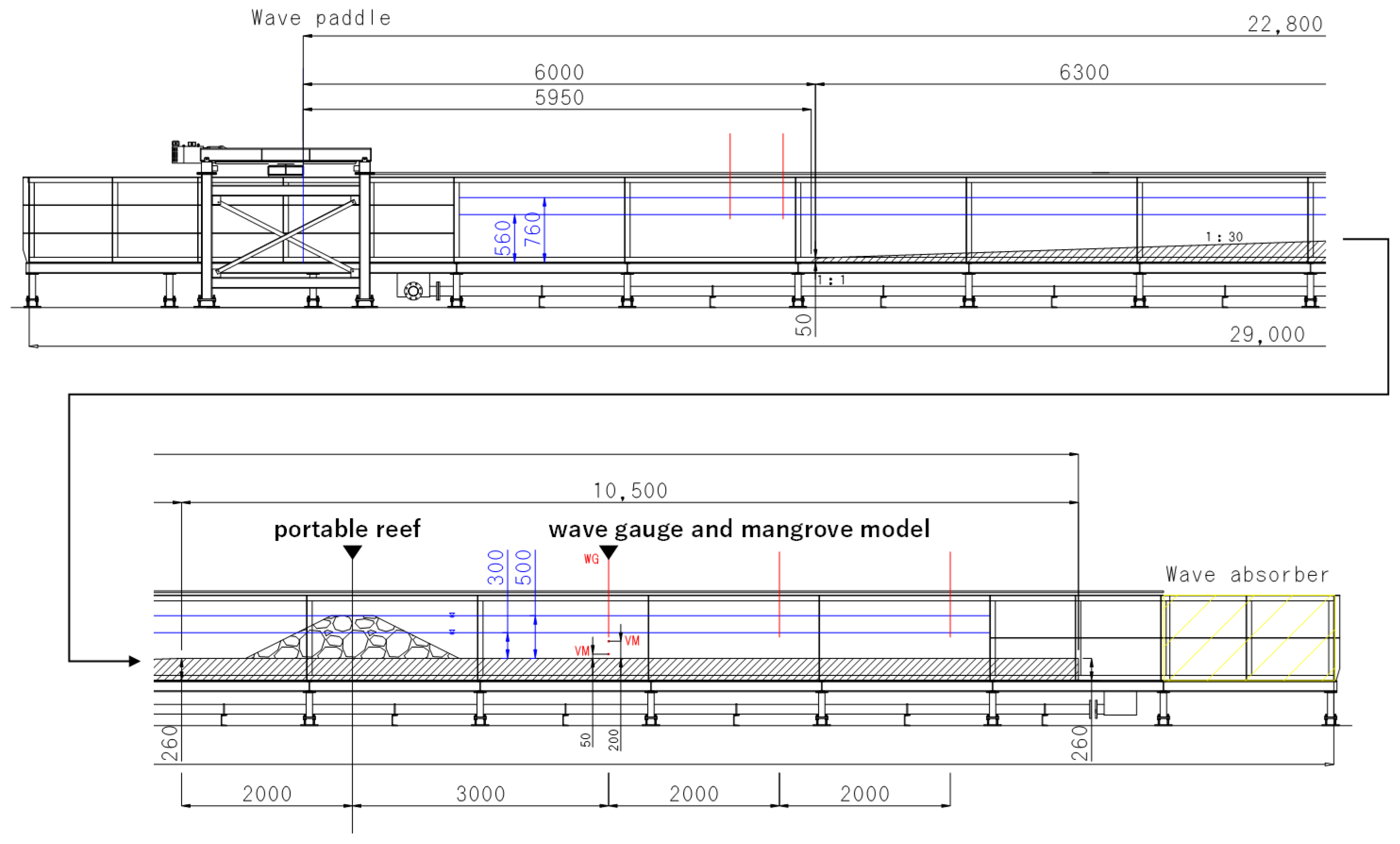
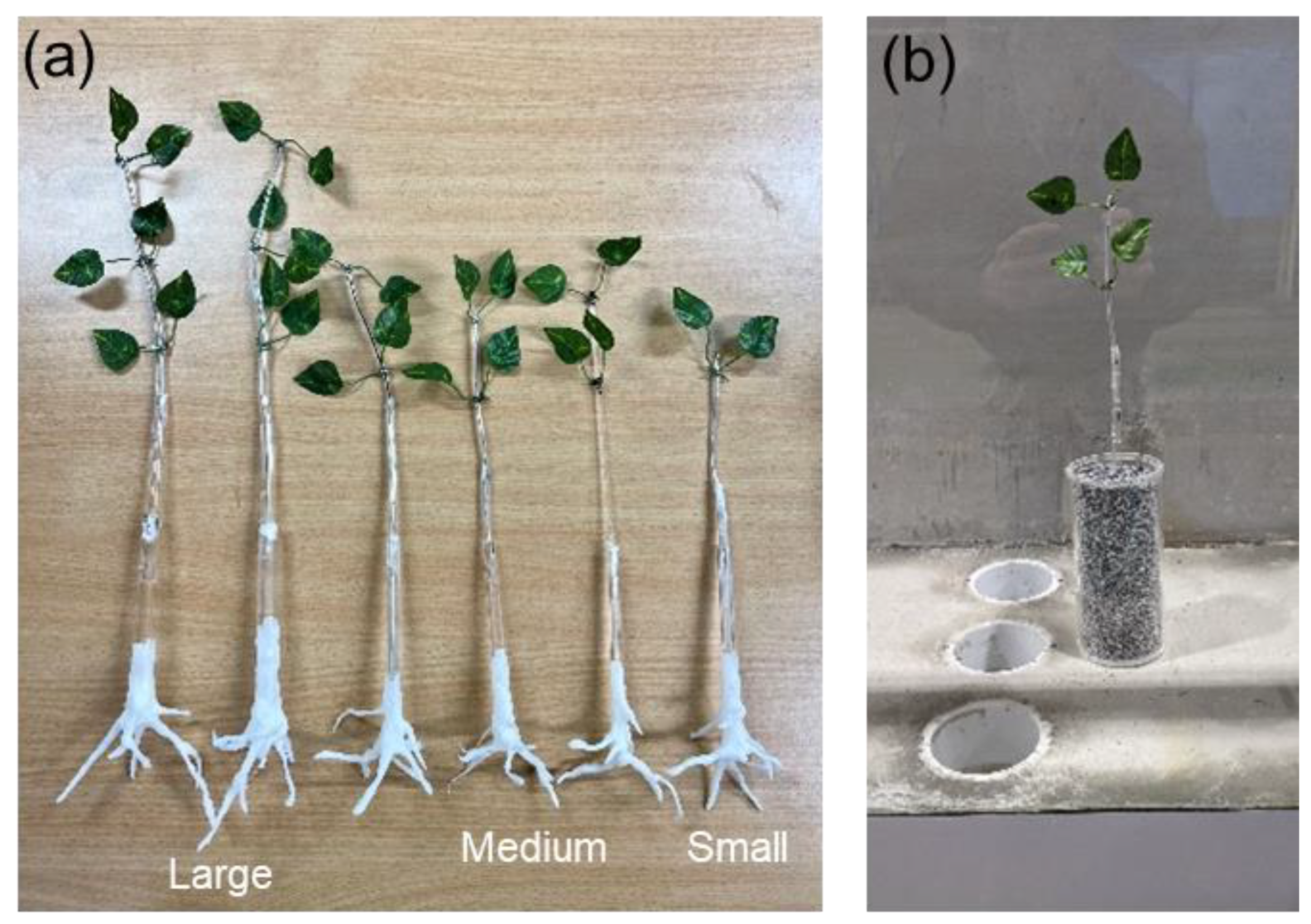
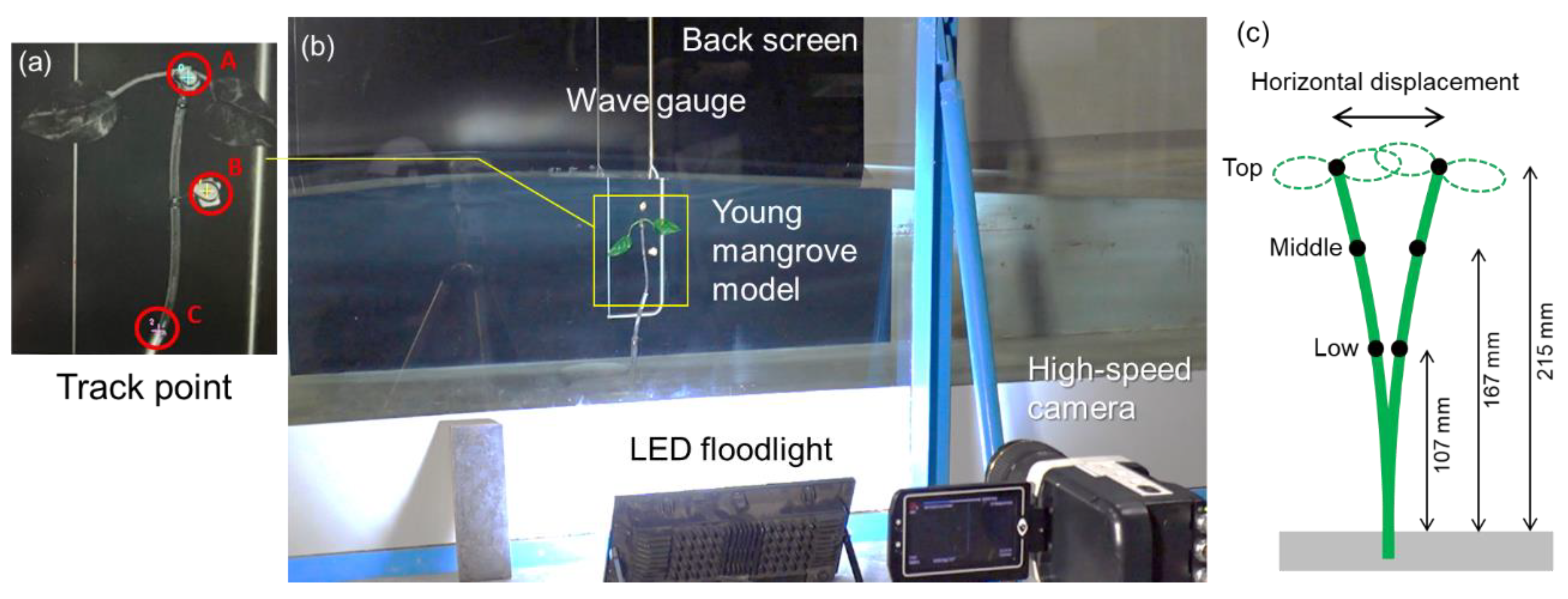
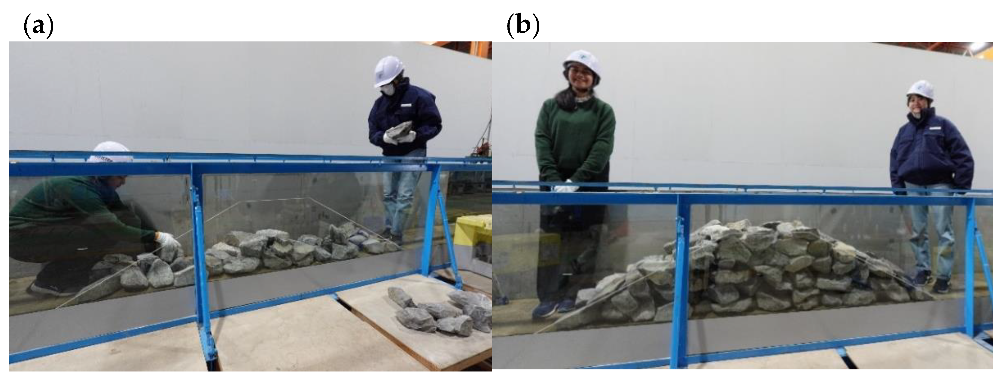
2.1. Wave Flume Experiment

An overview of the wave flume utilized in this research is provided in Figure 1. The wave flume measures 29 m in length, 0.5 m in width, and 1.0 m in height, featuring a wave absorber positioned at the end of the channel. This wave absorber consists of a bundle of curled thin wires, with a length of 2 m in the direction of the channel. The wave generation system is also equipped with a system that actively absorbs reflected waves based on the method of Frigaard and Brorsen [26].
To facilitate the anchoring of the mangrove model, a 0.26 m thick mortar bed was constructed to create a hole for installing a cylinder. Without this hole, the cylinder holding the mangrove models would have to be placed directly on the flume bed, inevitably affecting the oscillatory behavior. Regular wave generation was employed to analyze the primary oscillatory characteristics of the mangrove models. A wave gauge (model CHT6-30, KENEK Co., Ltd., Tokyo, Japan) was strategically placed at the same location as the mangrove models, specifically 3 m behind the reef, to capture wave data at a sampling frequency of 20 Hz. Each experimental trial lasted approximately 90 s; however, a 1 min interval, from 20 s to 80 s, was selected as the valid experimental timeframe for further analysis to ensure data consistency across various cases. The wave transmission coefficient was determined by calculating the ratio of the wave height under reef conditions to that in the absence of reefs, utilizing the 1 min dataset.
The incident wave heights were modulated such that the target wave heights without reef conditions were 8, 12, and 16 cm at the mangrove model location, whereas the wave period was set constant at 2 s (Table 1). The experiments were performed at two specific depths: 30 cm, representing medium tide, and 50 cm, indicating high tide. These experimental conditions were based on the insights provided by Sreeranga et al. [11] and Takagi [27], who evaluated the wave and tidal levels during normal weather and severe typhoon events affecting the mangrove forest on Amami Island, Japan. Their research revealed using a coupled weather, wind wave, and storm surge model that the offshore wave periods exceeded 6 s as a strong typhoon approached, whereas in the innermost bay area, where the mangrove forest is located, the wave periods were notably shorter, averaging around 2 s, and the wave heights were smaller than 15 cm [27]. Therefore, the wave period for the experimental setup was defined as 2 s. The wave conditions in wave experiments are often determined based on the Froude similarity law. In this experiment, the similarity law was not specifically considered because the present experiment was almost at the real scale, accounting for the conditions of a mangrove forest at our study site, which is located in the innermost part of Sumiyo Bay on Amami Island, Japan.
Although the waves generated in the experiment are small, even this level of wave would be damaging to young mangroves. Sreeranga et al. [11] conducted a manual wave generation test on Amami Island to test the toppling limits of young mangroves against waves and found that a one-month-old mangrove was completely submerged under water by the continuous action of a 10 cm wave height.
In this experiment, the slope between the offshore and shore-side beds was maintained at a ratio of 1:30. This slope is considered to be steeper than that of a natural coast with mangrove vegetation. For example, the coastal slope of the Amami mangrove forest was approximately 1:100 [27]. The beach slope affects the type of wave breaking and run-up distance; nevertheless, in this study, the effect of the slope is considered less important because the focus is on the difference in wave transmission due to the presence or absence of the portable reef and the oscillatory characteristics of young mangroves (i.e., the wave deformation process from offshore to the shore is not very important). In addition, the location where nature-based solutions are deployed may not only be a mild beach but also a steep beach where larger waves directly hit the shore.
Before conducting the reef-related experiments, the oscillatory behavior of the mangrove model was meticulously monitored without the presence of the reef to investigate the dynamics and behavior of the model under unprotected conditions. The reflection coefficients (i.e., the performance of the wave absorber), measured in the absence of the portable reef, ranged from 0.23 to 0.29. These coefficients were obtained from the time series of the water levels at two locations on the offshore side using the method of Goda and Suzuki [28]. Thus, in the absence of a portable reef, the mangrove models were slightly affected by the reflected waves from the edge of the flume; nevertheless, the effect was practically negligible.
A real reef structure was constructed approximately 3 m offshore from the mangrove model to evaluate the plant oscillations under protected conditions. The crest of the reef was strategically situated 20 cm above the medium tide level (depth: 30 cm) and was in alignment with the high-tide level (depth: 50 cm).
Although the incorporation of live mangroves into the wave flume would have been ideal for a more realistic assessment, the risk of damage to these delicate plants during repeated wave tests warranted a cautious approach. The loss of fragile leaves can significantly alter the oscillatory dynamics of the mangrove model. To avoid such uncertainties, durable mangrove models were created based on observations of Kandelia obovate species through field surveys of the Amami mangrove forest and indoor mangrove growth tests [11,12]. The three distinct sizes of the model plants utilized herein are depicted in Figure 2. The structures were constructed using a combination of plastic soft tubes, which served as the upper flexible stems, and acrylic cylindrical tubes, functioning as the lower rigid stems. Each stem was equipped with two to six leaves, attached using nonwoven material. To enhance both the stiffness and the elasticity, a stainless-steel spring rod with a diameter of 1 mm was inserted into the soft tubes (external diameter: 7 mm). The roots of these models were crafted from polymorph-moldable plastic pellets. Since the pairs of leaves grew in the early months, we created three model types (2-, 4-, and 6-leaf), which were denoted as the small, medium, and large models, respectively. The stiffness of the model was not necessarily the same as that of a real young mangrove; rather, we created the model using slightly stronger materials to withstand repeated wave action. Takagi et al. [12] compared the oscillation of a 2-month-old mangrove (Kandelia obovata) and a model mangrove using the same material as in the present experiment, and they found that the free oscillation period in air was less than 0.5 s in both cases. In the present experiment, 2 s waves were generated, which is longer than the natural period of the model mangrove, implying that the elastic models were shaken by the wave forces and that no resonance between the waves and the model is expected to occur.
To assess the differences in the oscillation patterns with and without the reef, a high-speed camera (Phantom Miro LC311, Vision Research Inc., Wayne, NJ, USA) recorded the oscillation of the mangrove model at a rate of 100 frames per second. The camera’s minimum resolution of approximately 0.1 mm was considered adequate for tracking the movements of elastic objects swaying in wave motions. The motion analysis of the mangrove model was conducted using automatic tracking software (Phantom Camera Control Ver 2.6, Vision Research Inc., NJ, USA), which monitored three distinct tracking points, as depicted in Figure 3. In this research, the displacement is defined as the total horizontal movement induced by cyclic wave forces.
Despite the careful measurements, challenges involving the loss of tracking were frequently encountered, especially in the medium and large plant models, as the tracking points were often submerged and emerged in tandem with the oscillation of the waves. For the small plant model that was completely underwater, the three tracking points were almost visible. Nonetheless, the analysis was incomplete (Table 1). To achieve data homogeneity, a series of analyses were performed, with a primary focus on the midpoint of the small model (Figure 3c).
In the context of this research, a “portable reef” is defined as a small rubble mound that can be easily constructed, dismantled, and relocated through human effort. According to a field survey by Zhang et al. [29], recently planted mangrove forests (2–6 years after planting) in Guangdong Province, China, withstood a storm surge of up to 1.74 m and a wind wave of up to 1.16 m caused by Typhoon Mangkhut in 2018 without critical damage or uprooting. Takagi [27] also investigated the survival of young planted mangroves in a calm bay environment. A strong typhoon (Typhoon Haishen) passed near Amami Island 16 months after the planting of Kandelia obovata. Although they were planted at the frontal edge of the intertidal zone, most of young mangroves survived without visible damage. Therefore, the performance of breakwaters should last for one to two years until the mangroves can withstand high waves. Large rubble breakwaters can serve as protection for mangrove plantations and are being implemented in some places (Figure 4). However, it is too cumbersome to move the stones once they are in place.
In contrast, portable reefs are structures that can be easily relocated so that the plantation area can be gradually expanded. If the stones are sufficiently light, they can be manually placed on a boat and carried a little further out to sea. This task can be undertaken by local community members without the need to hire professional construction workers. To evaluate the feasibility of masonry work within a local community, in this experiment, a reef was constructed in the wave flume, predominantly by two female members, with assistance from male members (Figure 5). The stones, each weighing up to 10 kg, were manually stacked without machinery; however, the construction of the reef within the 0.5 m wide flume required ~30 min to complete.

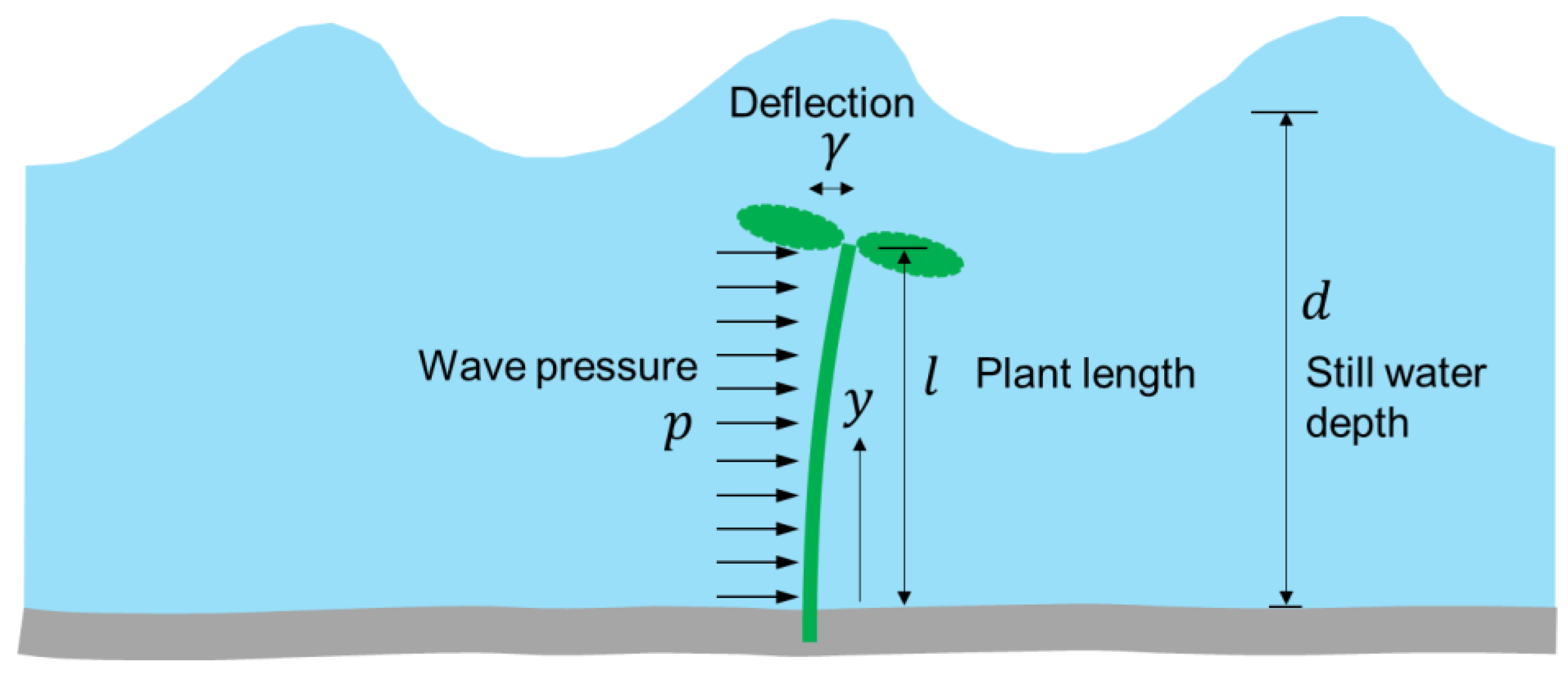
2.2. Analytical Solution for Plant Oscillation

In mature mangroves, the wave energy attenuation due to the root density, which varies with the water depth, and the trunk diameter complicate the modeling [30]. In contrast, young mangroves have no aerial roots after planting, making modeling simple. Instead, young mangroves are characterized by their high elasticity, exhibiting significant deflection when subjected to wave action, as demonstrated in Figure 6. In their study, Takagi et al. [12] proposed an analytical solution for the displacement of the plant, denoted as γ, represented in the following equation:
d 2 γ d t 2 + 2 c ω 0 d γ d t + ω 0 2 γ = F m cos ω t
where t represents the time, m signifies the mass, F denotes the wave force, ω and ω0 represent the angular frequencies of the wave and plant, respectively, and c refers to the viscosity damping coefficient.
The horizontal displacement at the top and an arbitrary height y from the ground can be calculated as follows:
γ t o p = p l 4 8 E I
γ = γ t o p 2 y l 2 4 3 y l 3 + 1 3 y l 4
where p denotes the wave pressure, l indicates the plant length, E represents the elastic modulus, and I symbolizes the second moment of area.
Three-point bending flexural tests are often used to determine E. These tests are performed under a gradually increasing load, i.e., static loading conditions. However, wave action is a dynamic loading process due to reciprocating motion, and hence, E may differ from the results obtained under static conditions. Consequently, we attempted to estimate E in Equation (2) by fitting it with the oscillation of an elastic body under waves in the experiment.
The wave force can be quantified using the following equation:
F ( t ) = 1 2 ρ C D ϕ u w cos 2 π t T u w cos 2 π t T 1 4 ρ C M π ϕ 2 u w 2 π T sin 2 π t T l
where T denotes the wave period, ρ indicates the water density, ϕ indicates the plant diameter, uw denotes the wave-induced fluid velocity, and CD and CM represent the drag and mass coefficients, respectively (refer to Takagi et al. (12) for details).
Although Equation (4) corresponds to linear waves, it does not necessarily provide the exact wave force due to breaking waves or nonlinear waves in shallow waters. A more accurate prediction of the wave forces is possible with advanced numerical modeling, but it may not be practical for the study of young mangrove oscillations. Note also that the wave force acting on an elastic body is not the same as the wave force acting on a rigid body because the force distribution changes with deflection. Naturally, the greater the deflection, the greater the difference in the force distribution between the elastic and rigid bodies. As described later, the maximum deflection displacement observed in this oscillation experiment was approximately 15 mm and the height of the elastic body was 215 mm (i.e., a deflection angle θ of nearly 4° is expected). For such small angles, the bending of the elastic body is considered negligible (i.e., tan θ θ ).
In scenarios where the damping constant is negligible, the second-order ordinary differential equation (presented in Equation (1)) can be resolved in the following manner:
γ = A cos ω t α cos α cos ω 0 t ω ω 0 sin α sin ω 0 t
where A represents the amplitude of the oscillation, which is influenced by various factors, including the wave height, wave period, and plant length. The variable α denotes the phase of the oscillation. When the angular frequencies of the wave and the plant converge closely, resonance occurs, leading to synchronization between the cyclic waves and the oscillatory motion of the plant. The natural period of a young mangrove of the species Kandelia obovata is estimated to be 0.36 s [12]. As mentioned earlier, this natural period is significantly shorter than the wave period of 2 s employed in the current regular wave experiments, suggesting that resonance did not occur in this context.

2.3. Applicability of Existing Wave Transmission Formula

Through benchmark tests, Hassanpour et al. [31] identified the d’Angremond formula as particularly robust among the existing wave transmission formulas for rubble mound breakwaters. d’Angremond et al. [32] proposed a formula for estimating the wave transmission coefficients Kt, which is applicable to both emerging and submerged breakwaters:
K t = 0.4 R H i + 0.64 B H i 0.31 1 exp 0.5 ξ   ( 0.075 < K t < 0.80 )
Here, H i denotes the incident wave height, R indicates the crest elevation, B specifies the crest width, and ξ represents the surf similarity parameter. Table 2 lists the symbols that are needed for the design of portable reefs.
The forthcoming sections will examine the applicability of the d’Angremond formula to actual-sized portable reefs, employing experimental data acquired from six distinct reefs with cross-sectional areas ranging from 0.57 to 1.05 m2 (Figure 7). The experimental data are detailed in Appendix A.
The portable reef utilized in the current experiment is shown in Figure 5, with its geometric configuration and dimensions detailed in Figure 7a. Figure 7b–f show the portable reefs examined in prior studies conducted by Sreeranga et al. [11,24,25]. As described in Section 2.1, the mangrove model oscillation experiments were performed for regular waves. In contrast, the evaluation to confirm the existing wave transmission formula was based on irregular (random) waves. The irregular wave experiments were carried out using a piston wave generator with the active wave absorption system (AwaSys, Aalborg University). A pair of offshore wave gauges were used to separate the incident and reflected waves using AwaSys. The waves were generated to reproduce a spectral waveform, termed the modified Bretschneider–Mitsuyasu spectrum [33]. The stones used in these experiments weighed between 2 and 10 kg and measured 15–20 cm, exhibiting a porosity of approximately 40%. Importantly, Figure 7f presents a reef constructed from 3 kg wave-dissipating blocks (tetrapods) characterized by a porosity of 50%.
The significant wave heights were calculated to facilitate the analysis of the wave transmission. Specifically, all these experiments were limited to a wave period of approximately 2 s. Although the results may not be comprehensive, the effect of the wave period on the wave transmission is expected to be relatively small [34].

3. Results and Discussion

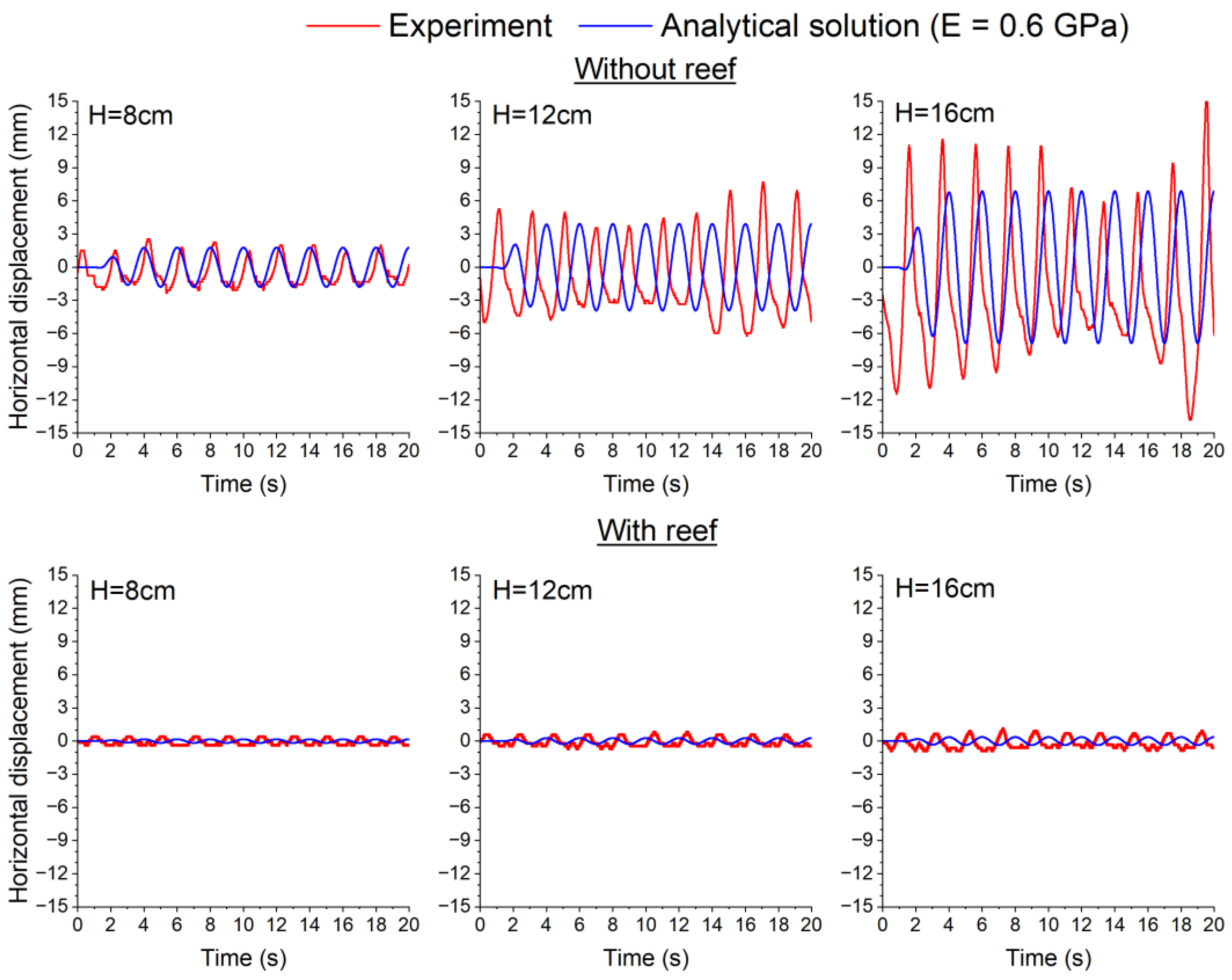
3.1. Summary of Experimental Results

Figure 8 presents a time-series analysis of the experimental findings, focusing on a 10 s interval within the valid 1 min dataset. Each figure delineates the fluctuations in the water levels alongside the oscillatory behavior of the mangrove model, contrasting scenarios with the presence and absence of the reef. Notably, the oscillations of the mangrove model display a considerable sensitivity toward wave activity. In the absence of the reef, the waveform maintains a relatively stable profile at a depth of 50 cm, while exhibiting significantly greater variability at a depth of 30 cm. This observation likely stems from the nonlinear characteristics of waves in shallow water environments.
A comparative analysis between the reef and non-reef scenarios reveals that the reef effectively dampens the oscillatory movements across all the observed instances. Specifically, the wave attenuation is substantially more pronounced at a depth of 30 cm in the presence of the reef, highlighting the critical influence of tidal conditions. Additionally, the waveform shows a tendency to bifurcate into two distinct peaks at a depth of 50 cm, an occurrence that was not observed at 30 cm. This bifurcation may be attributed to the turbulence generated by the wave breaking over the reef structure. Previous studies have established that the wave spectrum transitions from a fundamental frequency to higher frequencies due to nonlinear interactions over submerged breakwaters [35]. As a result, these interactions empower the reef to create significant turbulence, especially during high-tide events, leading to the regular but non-constant oscillation patterns of vegetation positioned behind the reef.
The performance of the reef is evaluated quantitatively in Figure 9a,b, which compare the extent to which the wave height and mangrove model oscillations are reduced by the reef. The wave heights and oscillatory horizontal displacements are the averaged measurements of approximately 30 waves recorded during a valid 1 min interval. The diagonal lines depicted in the figures indicate instances where the horizontal and vertical values are equivalent. At a depth of 50 cm, the wave attenuation is noticeably lesser than that observed at a depth of 30 cm, while the oscillations are markedly pronounced. Figure 9c demonstrates a tendency in the plots toward greater oscillatory reductions, implying that the oscillations experienced by the mangroves could be diminished to a greater extent than the wave heights themselves.
As expressed in Equation (4), the force exerted on the plant stem is directly proportional to the square of the flow velocity. Linear theory posits that the flow velocity correlates directly with the wave height; consequently, the force is proportional to the square of the wave height. This relationship may elucidate the observed phenomenon of greater oscillatory attenuation in the plant compared to the attenuation of wave heights.
Figure 10 illustrates the variability in the oscillatory response to waves, contingent upon the dimensions of the mangrove model. As detailed in Table 1, the track analysis for the medium- and large-sized mangrove models exhibits lower accuracy; nonetheless, the nine plots presented in this figure are classified as Class A (where data acquisition was nearly flawless), with the exception of one plot categorized as Class B (indicating a partial failure in data acquisition).
The largest displacements occurred in the small model, whereas the displacements in the medium and large models were both small. This is because the small-scale model was entirely submerged in water and subjected to wave pressure uniformly across its surface, whereas the leaf elements of the medium and large models extended partially or fully into the air, thereby contributing to the oscillation suppression. This finding corroborates previous field observations that demonstrated a reduction in oscillation as young mangroves mature, becoming taller and stiffer [11,12].

3.2. Detailed Analysis of Oscillatory Characteristics

Figure 11 presents the correlation between the wave height and the oscillatory displacement of the mangrove model, drawing from both the experimental and analytical data. As the oscillation patterns exhibited spatial variations, horizontal displacements were recorded at three distinct heights of the small mangrove model.
To accurately estimate these displacements analytically using Equations (2) and (3), it was imperative to determine a suitable constant for the elastic modulus. The selected value of E = 0.6 GPa aligns closely with the experimental findings, particularly at the midpoint of the measurement. Furthermore, according to the MatWeb database of material properties (https://www.matweb.com/), this modulus is comparable to that of medium-density polyethylene, which ranges from 0.35 to 0.84 GPa, reflecting the similar characteristics of the materials utilized in the present mangrove model.
Hang et al. [36] conducted a three-point bending test on a branch cut from a 3 m high Kandelia obovate, showing that the elastic modulus ranged from 0.75 to 1.81 GPa for branch diameters of 5.9 mm to 34.9 mm. The elastic modulus of the mangrove model used in this study was estimated to be 0.6 GPa for a diameter of 7 mm, which is similar to the value of 0.75 GPa for 5.9 mm. Note, however, that the elastic modulus in the present study is essentially different from that obtained by Hang et al. [36]. We estimated the elastic modulus under a dynamic loading condition using Equation (2), as described in Section 2.2.
The larger sway range at the top position in the experiment compared to the analytical results may be caused by the extra force received by the attached leaves, which was not modeled in the analysis. Although the experiment successfully generated regular waves, the resultant wave characteristics were not consistently uniform, which may have influenced the observed oscillations.
Notably, the relationship between the wave height and the displacement exhibited a quadratic rather than a linear increase. The damping effect on the oscillations was considerably more pronounced compared to the attenuation of the wave heights, as elaborated in the preceding section. Figure 12 provides a comparative analysis of the experimental results with and without the presence of a reef, revealing that the oscillations diminish significantly as the wave height decreases under the experimental and analytical settings.
Furthermore, beyond the horizontal displacement, young mangroves may incur damage due to the intense acceleration experienced by their leaves. To elucidate this issue, Figure 13 illustrates the acceleration and displacement observed at the apex of the small mangrove model. Although the elastic modulus of the model is estimated to be 0.6 GPa, it is important to note that the actual elasticity of young mangroves is likely to vary. For instance, a reduction in the elastic modulus to 0.3 GPa would double the horizontal displacement, whereas an increase to 1.2 GPa would halve the displacement. The data indicate that acceleration increases with a decrease in stiffness, suggesting that younger mangroves with softer structures are more susceptible to oscillatory movements.
Figure 13b further illustrates the differential impact of the wave period on the displacement and acceleration. Specifically, the displacement is relatively insensitive to changes in the wave period, whereas the acceleration demonstrates significant fluctuations in response to varying wave periods. If the wave height is 18 cm and the period is as short as 1 s, the acceleration is 2.8 times that at 2 s, which is greater than the acceleration due to gravity (=9.8 m/s2). This finding indicates that an increase in the presence of short-period waves is associated with heightened oscillatory movements in plants, which could be detrimental to the health of young mangroves. Significantly, experiments involving waves characterized by even shorter periods may trigger disproportionately large oscillations due to the resonance effects with the natural frequency of young mangrove species, as previously highlighted.

3.3. Benefits of Reduced Oscillation

Although not the primary objective of this paper, the possibility of young mangroves being damaged by waves is also briefly discussed. We have previously conducted uprooting resistance tests on young mangroves in the mangrove forest on Amami Island. As shown in Figure 14, the maximum resistance of several young mangroves (Kandelia obovate), considered to occur approximately 1 to 6 months after germination, was tested with a digital force gauge and found to be approximately 10 to 30 N. Figure 15 shows the wave force calculated using Equation (4) for the small plant model subjected to regular waves with a wave height of 16 cm and a period of 2 s. Since the stem diameter is assumed to be small (7 mm), the maximum wave force is estimated as small as 0.3 N.
The wave forces are transmitted to the roots and produce a vertical uprooting force; nevertheless, the latter force is expectedly smaller than the former one. Therefore, in natural environments, root uprooting is not expected to occur due to wave forces. However, if the ground experiences erosion by waves, the resistance of the roots can reduce; this possibility will need to be considered separately.
The effect of oscillation on the damage to the leaves was also not investigated in this study because it has to be studied on actual mangroves rather than model mangroves. In this regard, it will be necessary to consider both the negative and positive aspects of plant oscillation. Strong oscillations caused by waves have a negative impact on mangroves because they can cause physical damage to mangrove leaves. Moderate oscillations, however, can have a positive influence on photosynthesis because they may agitate the surrounding air and promote CO2 absorption and plant growth [37]. Thus, oscillations also affect the temperature of the leaf surface. Cold stress can negatively affect plant growth and proper functioning because it reduces the photosynthetic capacity and causes physical damage to the leaf tissue [38]. On the other hand, an increase in temperature is believed to decrease photosynthesis and increase respiration in plants, causing a number of negative impacts on the ecosystem [39]. Therefore, the design of portable reefs will need to strike a balance between the complete elimination of waves and the allowance of some waves.

3.4. Applicability of d’Angremond Formula to Portable Reefs

Figure 16 compares the wave transmission coefficients (Kt) calculated using the d’Angremond formula (Equation (6)) and the experimental Kt values obtained from the six portable reef structures (Figure 7).
The d’Angremond formula consistently underestimated the Kt values relative to the experimental data gathered from the portable reefs. Notably, the formula yielded a minimum Kt value of 0.075 across all the conditions where the reef had emerged, leading to an overestimation of the wave attenuation. This was especially evident when waves traversed the porous reef structure.
In the present full-scale portable reef experiments, a 1:1 scale ratio was employed, ensuring that both the wave dynamics and the stone dimensions were accurately represented at actual size. In contrast, the existing formula typically necessitates that the stones used in experimental settings adhere to similarity principles, often resulting in smaller stones than those implemented at the construction site. For instance, in a European project (DELOS) that comprehensively studied the effectiveness and stability of low-crested structures in dissipating waves, the sizes of the rubble stones used in the experiments were as small as 3.3 cm and 1.5 cm for the outer armor and inner core, respectively [40]. Previous investigations into wave transmission have utilized relatively small stones, with diameters measuring 5.9 cm [34], 4 cm [41], and 6.3 cm [31], despite the need for design waves to exceed several meters in height. In contrast, the current portable reef design is characterized by a single-layer structure, whereas traditional rubble mound breakwaters consist of multiple components. These components include cores, underlayers, armor stones, berms, crown walls, scour protection, and toes, incorporating stones or blocks of varying sizes [42].
Research by Van der Meer and Daemen [43] indicated that smaller stones contributed to diminished wave transmission, suggesting that the wave energy is attenuated more effectively. This phenomenon can be understood through the concept of quadratic resistance, which arises from the turbulence generated by flow through a permeable structure; this resistance increases as the size of the particles decreases [44]. Consequently, the current wave transmission formulas may not be applicable to portable reef scenarios, as they often overestimate the wave energy attenuation. This overestimation consequently leads to an underappreciation of the oscillatory movements experienced by young mangroves located behind the reef.

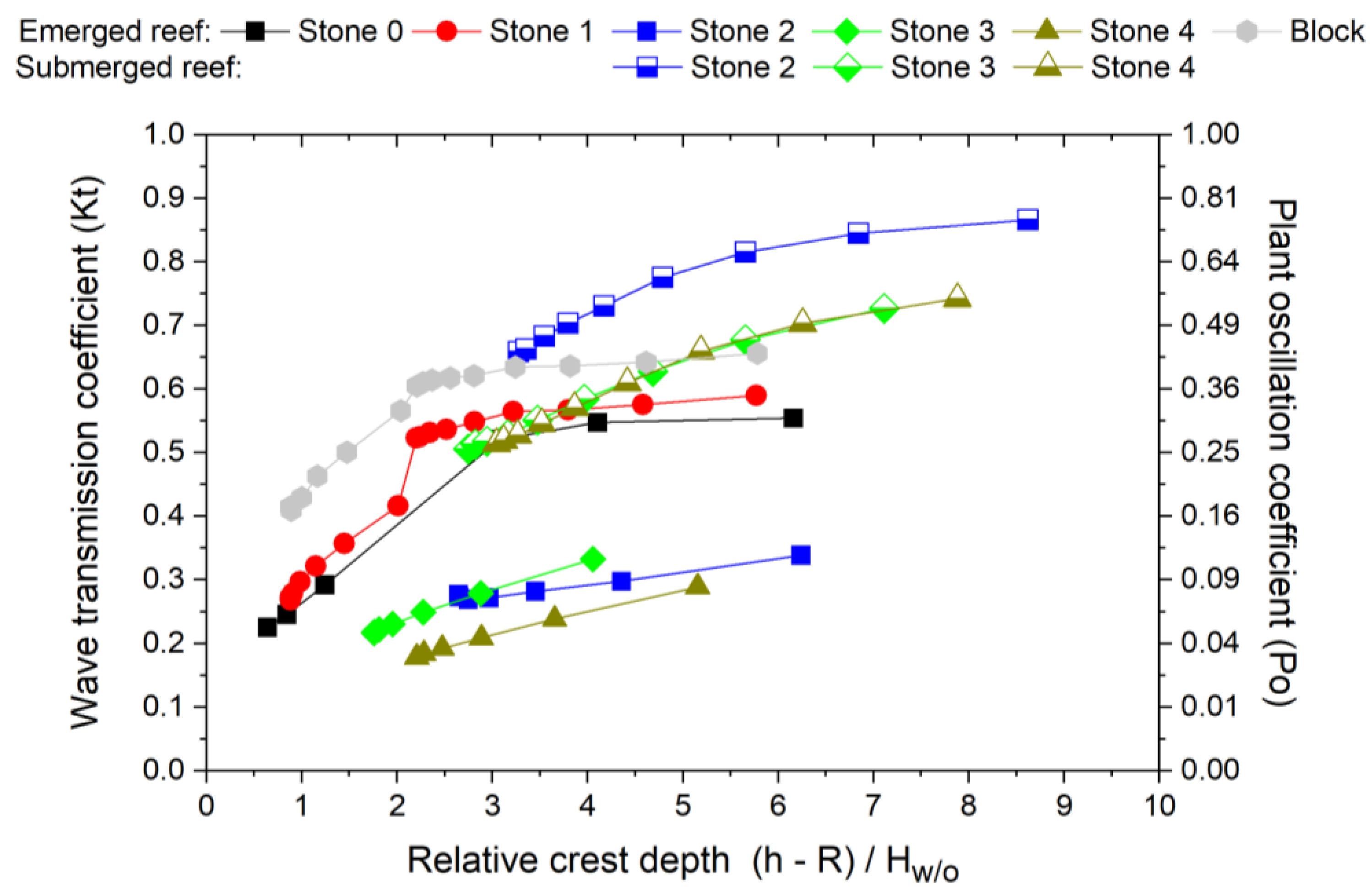
3.5. Wave Transmission Chart for Portable Reef Design

As discussed, the existing wave transmission formulas appear ill-suited to the design of portable reefs. Instead, an estimation chart of the wave transmission coefficient (Kt) was proposed (Figure 17) based on the real-size portable reef experiments with six different dimensions. The right vertical axis represents the plant oscillation coefficient (Po), which quantifies the oscillatory movement of young mangroves in both the presence and absence of reefs. This coefficient is based on the principle that the oscillatory displacement is theoretically proportional to the square of the wave height, mathematically expressed as Po = Kt2.
Although the chart relies on data pertaining to significant wave heights (Hs), utilizing the mean or maximum wave heights could offer a more practical approach for community-based assessments. Figure 18 demonstrates the conversion process from the mean or maximum wave height to the significant wave height, illustrating the findings derived from the experimental data. The correlation between the significant wave height and the mean wave height aligns closely with the theoretical relationship established by the Rayleigh distribution, represented as Hs = 1.6∙Hmean.
The commonly used wave transmission formulas often incorporate the relative crest height (R/H) to depict the reef geometry; however, the present chart employs the relative crest depth, defined as (hR)/H. This modification enhances the clarity of the plot, particularly by distinguishing between emerged and submerged reefs, as each line is continuously represented.
Within the specified range of the relative crest depth of 1–9, the Kt values for the portable reefs exhibited variability, spanning from 0.15 to 0.9, with a cross-sectional area ranging from 0.57 to 1.05 m2. Notably, the wave transmission phenomena were most significant when the reef crest was submerged, highlighting the critical role of the reef geometry in influencing the wave dynamics. For example, the reef conditions emerging in Stones 2, 3, and 4 can be expected to provide adequate wave attenuation in the range of Kt = 0.15–0.35, whereas it will be greater than 0.5 under submerged reef conditions. To optimize the energy dissipation, it is beneficial to elevate the reef crest above the designated tidal level.
However, during high tide, it may be challenging to secure an adequate number of stones to raise the reef crest. Even when the coefficient Kt is relatively high, it is possible to observe a low value of Po, particularly if the attenuation of the plant oscillation surpasses that of the wave attenuation. Additionally, previous studies suggest that a duration of less than one to two years is sufficient to protect young mangroves [11,27,29]. Thus, submerged reefs may prove effective in areas characterized by calm wave activity.
The following procedure details the application of this chart:
i.
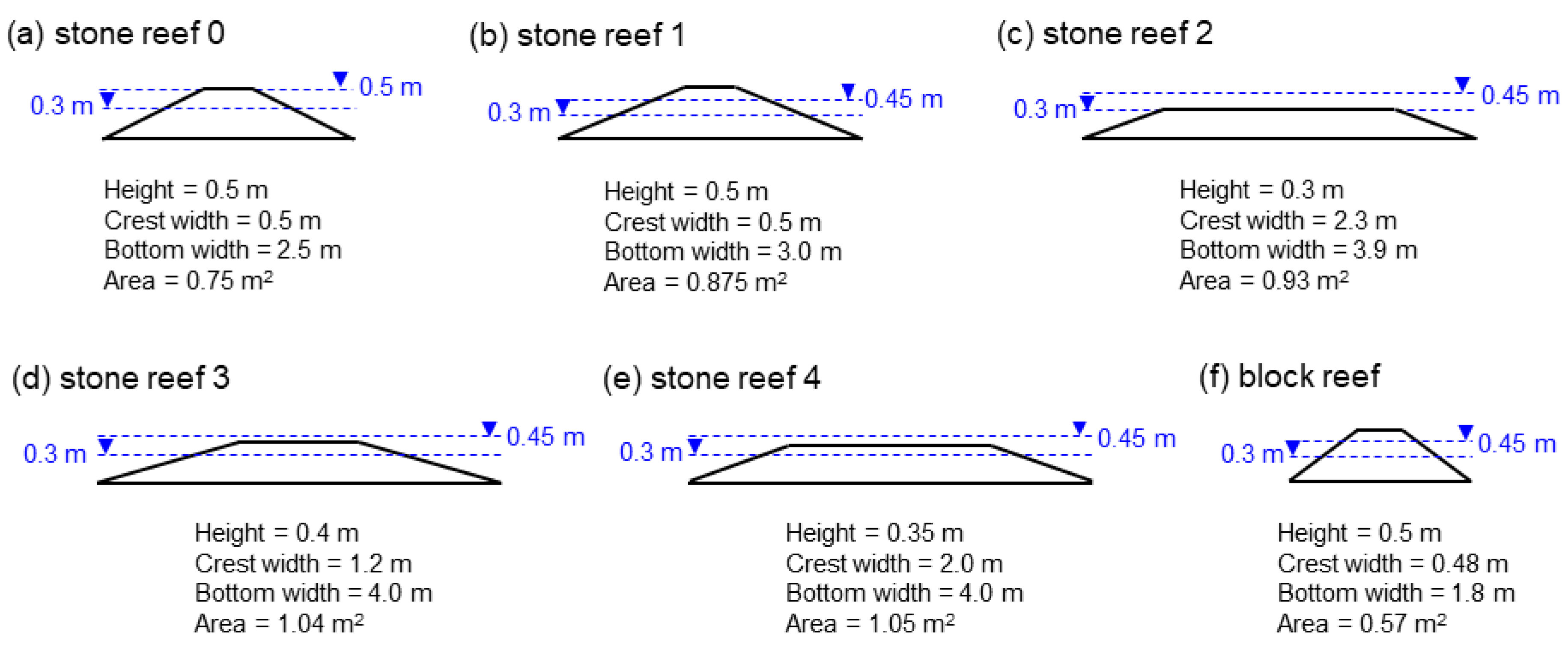
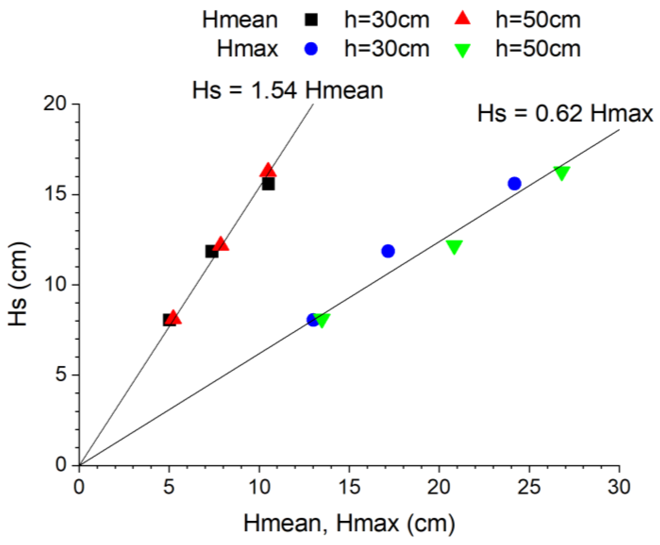
The water depth and significant wave height at the proposed reef site should be assessed, followed by the calculation of the relative crest depths for six different reef geometries (refer to Figure 7). In cases where only the mean or maximum wave height data are available, this information needs to be converted to the significant wave height, as demonstrated in Figure 18.
ii.
Consider whether the reef will be submerged or emergent under the designed tidal conditions. If both submerged and emergent configurations are feasible, one should opt for an emergent reef alternative.
iii.
The allowable wave transmission and/or plant oscillations (coefficients Kt and Po) should be calculated for the proposed reef using Figure 17 to ensure compliance with the established allowable limits. If these criteria are not satisfied, the height of the reef crest increases.
In addition, since portable reefs are intended for the initial protection of mangroves and are not a permanent measure, care should be taken to ensure that the cross-sections are not too large.

4. Conclusions

In this study, we conducted real-scale wave experiments and analytical assessments focusing on young mangrove models situated behind a community-based breakwater, referred to as a “portable reef”. Wave dissipation plays a crucial role in safeguarding young mangroves, which do not require the robust dimensions typical of conventional civil engineering breakwaters. However, there is a notable absence of design guidelines related to their minimum dimensions. Although the utilization of portable reefs has led to a significant reduction in the wave height, even minor wave actions can exert considerable stress on young mangroves, thereby posing a serious threat to their survival. The outcomes of this research are pivotal for the effective design of portable reefs, as outlined below:
The present findings indicate that it is possible to reduce the wave transmission coefficient, Kt, to below 0.3 when the reef is in an emerged state. Conversely, Kt exhibits a significant increase when the reef crest is submerged. Although some degree of wave transmission is inevitable, the careful placement of portable reefs can effectively reduce the oscillation experienced by young mangroves to negligible levels. This is because the damping effect on the plant oscillations is greater than the damping of the waves themselves.
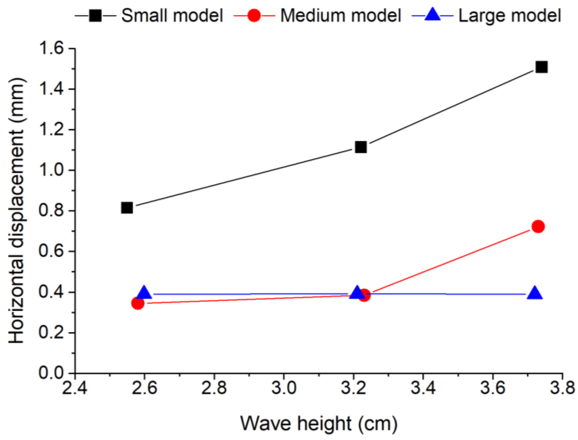
The results of our experiments and analytical models provide valuable insights into the various factors that pose risks to young mangroves. Notably, an increase in the short-period wave activity is associated with heightened oscillations in plant structures, which can be detrimental to low-rigidity mangroves at critical early developmental stages. As these young mangroves grow and their leaves rise above the water surface, the oscillation effects diminish.
Existing wave transmission equations such as the d’Angremond formula may not be appropriate for the design of portable reefs, as they tend to overestimate the efficacy of such structures. To address this gap, we have developed a new chart that illustrates the relationship between the wave transmission and the plant oscillations behind portable reefs. Using this chart, the required cross-section can be easily determined based on several parameters, such as the design tide level, wave height, and reef geometries, which will aid in the design and implementation of these protective measures for young mangrove ecosystems.
However, the present study was conducted under limited conditions. Although the experiment used a model mangrove, the actual elasticity of young mangroves is likely to vary. Kandelia obovate was specified as the mangrove species in this study, but young mangroves of other species may grow at different rates and in different ways. The short-period wave of around 2 s was carefully analyzed. Nonetheless, the effect of a longer period should also be considered. Furthermore, the behavior of mangrove oscillations may change as bed scouring by waves is unavoidable. Since the effects of oscillation on young mangroves can be both negative and positive, the extent to which waves need to be reduced by portable reefs should also be investigated in detail. Future studies on this topic should consider real environmental conditions. In addition to an experimental approach, a numerical approach would be useful for future studies; e.g., computational fluid dynamics (CFD) for accurate analysis of wave dissipation through porous rubble structures, multiphase CFD for assessing soil erosion and accretion behind the portable reef, or fluid–structure interaction (FSI) models between young mangrove oscillation and wave dynamics.

Author Contributions

Conceptualization, H.T.; Validation, H.T.; Formal analysis, H.T. and F.T.P.; Investigation, F.T.P., J.M. and S.K.; Resources, J.M. and S.K.; Data curation, F.T.P., J.M. and S.K.; Writing—original draft, H.T.; Visualization, H.T.; Supervision, S.K.; Project administration, J.M.; Funding acquisition, H.T. All authors have read and agreed to the published version of the manuscript.

Funding

This research was partially funded by a grant awarded to the Institute of Science Tokyo (formerly Tokyo Institute of Technology) (Japan Society for the Promotion of Science, 23K04343).

Data Availability Statement

The original contributions presented in this study are included in the article. Further inquiries can be directed to the corresponding author.

Conflicts of Interest

Authors Jun Mitsui and Shin-ichi Kubota were employed by the company Fudo Tetra Corporation. The remaining authors declare that the research was conducted in the absence of any commercial or financial relationships that could be construed as a potential conflict of interest.

Appendix A

Table A1. Specifications of the portable reefs considered in this study and all the experimental data.
Reef NameReef Height (cm)Crest Width (cm)Area (cm2)Depth h (cm)Crest Elevation R (cm)Emerge or SubmergeH w/o Reef (cm)H w/ Reef (cm)Relative Crest Depth
(h-R)
/Hw/o
Wave Transmission Coefficient Kt
Stone reef 0505075003020Emerge8.052.351.240.29
3020Emerge11.852.910.840.25
3020Emerge15.593.510.640.23
500Emerge8.124.506.160.55
500Emerge12.186.674.110.55
500Emerge16.268.473.080.52
Stone reef 1505087503020Emerge4.972.072.010.42
3020Emerge6.922.471.450.36
3020Emerge8.732.811.150.32
3020Emerge10.163.020.980.30
3020Emerge11.033.070.910.28
3020Emerge11.343.040.880.27
3020Emerge11.373.110.880.27
455Emerge6.934.095.770.59
455Emerge8.745.034.580.58
455Emerge10.545.983.800.57
455Emerge12.427.013.220.56
455Emerge14.237.802.810.55
455Emerge15.878.522.520.54
455Emerge17.079.082.340.53
455Emerge17.889.382.240.52
455Emerge18.179.512.200.52
Stone reef 2302309300300Emerge4.811.636.240.34
300Emerge6.892.054.350.30
300Emerge8.692.453.450.28
300Emerge10.122.752.960.27
300Emerge10.922.942.750.27
300Emerge11.323.092.650.27
300Emerge11.343.142.650.28
45−15Submerge6.966.038.620.87
45−15Submerge8.777.416.840.84
45−15Submerge10.618.655.660.82
45−15Submerge12.539.724.790.78
45−15Submerge14.3710.504.180.73
45−15Submerge15.8011.123.800.70
45−15Submerge16.9311.573.540.68
45−15Submerge17.8911.863.350.66
45−15Submerge18.3212.073.280.66
Stone reef 34012010,4003010Emerge4.931.644.060.33
3010Emerge6.951.942.880.28
3010Emerge8.792.192.280.25
3010Emerge10.242.361.950.23
3010Emerge11.042.451.810.22
3010Emerge11.362.471.760.22
3010Emerge11.372.461.760.22
45−5Submerge7.035.117.110.73
45−5Submerge8.845.995.660.68
45−5Submerge10.676.704.690.63
45−5Submerge12.617.363.970.58
45−5Submerge14.397.933.470.55
45−5Submerge15.808.353.160.53
45−5Submerge16.998.802.940.52
45−5Submerge17.729.102.820.51
45−5Submerge18.199.202.750.51
Stone reef 43520010,500305Emerge4.851.405.150.29
305Emerge6.841.633.650.24
305Emerge8.671.812.880.21
305Emerge10.101.942.480.19
305Emerge10.952.012.280.18
305Emerge11.322.022.210.18
305Emerge11.342.022.200.18
45−10Submerge6.985.187.880.74
45−10Submerge8.796.186.260.70
45−10Submerge10.606.995.190.66
45−10Submerge12.457.594.420.61
45−10Submerge14.238.123.870.57
45−10Submerge15.648.533.520.55
45−10Submerge16.848.883.270.53
45−10Submerge17.649.163.120.52
45−10Submerge18.069.293.050.51
block reef504857003020Emerge4.912.782.040.57
3020Emerge6.793.401.470.50
3020Emerge8.593.981.160.46
3020Emerge10.024.301.000.43
3020Emerge11.264.610.890.41
3020Emerge11.354.710.880.41
455Emerge6.924.545.780.66
455Emerge8.675.574.610.64
455Emerge10.486.673.820.64
455Emerge12.357.843.240.63
455Emerge14.258.852.810.62
455Emerge15.649.662.560.62
455Emerge16.9010.382.370.61
455Emerge17.6210.752.270.61
455Emerge18.1210.962.210.60

References

  1. Lewis, R.R. Ecological engineering for successful management and restoration of mangrove forests. Ecol. Eng. 2005, 24, 403–418. [Google Scholar] [CrossRef]
  2. Zimmer, K. Many Mangrove Restorations Fail. Is There a Better Way? Knowable Magazine. 2021. Available online: https://knowablemagazine.org/content/article/food-environment/2021/many-mangrove-restorations-fail (accessed on 1 January 2025).
  3. Primavera, J.H.; Esteban, J.M.A. A review of mangrove rehabilitation in the Philippines: Successes, failures and future prospects. Wetl. Ecol. Manag. 2008, 16, 345–358. [Google Scholar] [CrossRef]
  4. IFRC. Breaking the Waves: Impact Analysis of Coastal Afforestation for Disaster Risk Reduction in Viet Nam; International Federation of Red Cross and Red Crescent Societies: Geneva, Switzerland, 2011. [Google Scholar]
  5. Kodikara, K.A.S.; Mukherjee, N.; Jayatissa, L.P.; Dahdouh-Guebas, F.; Koedam, N. Have mangrove restoration projects worked? An in-depth study in Sri Lanka. Restor. Ecol. 2017, 25, 705–716. [Google Scholar] [CrossRef]
  6. Fauzi, N.F.M.; Min, T.H.; Hashim, A.M. Assessment of mangrove replanting site at Kg Tanjung Kepah, Lekir, Perak. IOP Conf. Ser. Earth Environ. Sci. 2020, 549, 012054. [Google Scholar] [CrossRef]
  7. Devaney, J.L.; Marone, D.; McElwain, J.C. Impact of soil salinity on mangrove restoration in a semiarid region: A case study from the Saloum Delta, Senegal. Restor. Ecol. 2021, 29, 13186. [Google Scholar] [CrossRef]
  8. Sidik, F.; Kusuma, D.W.; Priyono, B.; Proisy, C.; Lovelock, C.E. Chapter 22-Managing sediment dynamics through reintroduction of tidal flow for mangrove restoration in abandoned aquaculture ponds. In Dynamic Sedimentary Environments of Mangrove Coasts; Elsevier: Amsterdam, The Netherlands, 2021; pp. 563–582. [Google Scholar]
  9. Elster, C. Reasons for reforestation success and failure with three mangrove species in Colombia. For. Ecol. Manag. 2000, 131, 201–214. [Google Scholar] [CrossRef]
  10. Thompson, B.S. The political ecology of mangrove forest restoration in Thailand: Institutional arrangements and power dynamics. Land Use Policy 2018, 78, 503–514. [Google Scholar] [CrossRef]
  11. Sreeranga, S.; Takagi, H.; Shirai, R. Community-based portable reefs to promote mangrove vegetation growth: Bridging between ecological and engineering principles. Int. J. Environ. Res. Public Health 2021, 18, 590. [Google Scholar] [CrossRef]
  12. Takagi, H.; Shirai, R.; Sreeranga, S. Oscillatory characteristics of young mangroves exposed to short-period waves. Sci. Total Environ. 2021, 790, 148157. [Google Scholar] [CrossRef]
  13. Erickson, A.A.; Saltis, M.; Bell, S.S.; Dawes, C.J. Herbivore feeding preferences as measured by leaf damage and stomatal ingestion: A mangrove crab example. J. Exp. Mar. Biol. Ecol. 2003, 289, 123–138. [Google Scholar] [CrossRef]
  14. van Bijsterveldt, C.E.J.; van Wesenbeeck, B.K.; Ramadhani, S.; Raven, O.V.; van Gool, F.E.; Pribadi, R.; Bouma, T.J. Does plastic waste kill mangroves? A field experiment to assess the impact of macro plastics on mangrove growth, stress response and survival. Sci. Total Environ. 2021, 756, 143826. [Google Scholar] [CrossRef]
  15. Holbert, J.; Sudrajat, D.J.; Nurhasybi; Yulianti. Alternative methods for reforestation and land rehabilitation to reduce the plastics waste in forestareas. IOP Conf. Ser. Earth Environ. Sci. 2019, 407, 012007. [Google Scholar] [CrossRef]
  16. Thampi, A.; Vedharajan, B.; Narayana, S.; Govindarajan, M.; Magalingam, R. Experiment on use of eco-friendly Palmyra nursery bag for mangrove restoration in Palk Bay, India. Restor. Ecol. 2023, 31, e13957. [Google Scholar] [CrossRef]
  17. Akbar, A.A.; Sartohadi, J.; Djohan, T.S.; Ritohardoyo, S. The role of breakwaters on the rehabilitation of coastal and mangrove forests in West Kalimantan, Indonesia. Ocean Coast. Manag. 2017, 138, 50–59. [Google Scholar] [CrossRef]
  18. Takagi, H. “Adapted mangrove on hybrid platform”—Coupling of ecological and engineering principles against coastal hazards. Results Eng. 2019, 4, 100067. [Google Scholar] [CrossRef]
  19. Schmitt, K.; Albers, T. Area coastal protection and the use of bamboo breakwaters in the Mekong Delta. In Coastal Disasters and Climate Change in Vietnam; Elsevier: Amsterdam, The Netherlands, 2014; pp. 107–132. [Google Scholar]
  20. Cuong, C.V.; Brown, S.; To, H.H.; Hockings, M. Using Melaleuca fences as soft coastal engineering for mangrove restoration in Kien Giang, Vietnam. Ecol. Eng. 2015, 81, 256–265. [Google Scholar] [CrossRef]
  21. Takagi, H.; Sekiguchi, S.; Thao, N.D.; Rasmeemasmuang, T. Do wooden pile breakwaters work for community-based coastal protection? J. Coast. Conserv. 2020, 24, 31. [Google Scholar] [CrossRef]
  22. Pranchai, A.; Jenke, M.; Berger, U. Well-intentioned, but poorly implemented: Debris from coastal bamboo fences triggered mangrove decline in Thailand. Mar. Pollut. Bull. 2019, 146, 900–907. [Google Scholar] [CrossRef]
  23. Saengsupavanich, C.; Ferren, V.; Magdalena, I.; Ariffin, E.H.; Sanitwong-Na-Ayutthaya, S. Using piles for wave reduction and coastal protection: A review. Reg. Stud. Mar. Sci. 2024, 77, 103638. [Google Scholar] [CrossRef]
  24. Sreeranga, S.; Takagi, H.; Shirai, R.; Kubota, S.; Mitsui, J. Numerical investigation on effectiveness of portable rubble mound breakwater for mangrove restoration. J. Jpn. Soc. Civ. Eng. Ser. B3 (Ocean Eng.) 2021, 77, 61–66. [Google Scholar] [CrossRef]
  25. Sreeranga, S.; Takagi, H.; Kubota, S.; Mitsui, J. An experimental study on oscillatory characteristics of young mangroves behind a portable reef. Coast. Eng. J. 2022, 65, 110–125. [Google Scholar]
  26. Frigaard, P.; Brorsen, M. A time-domain method for separating incident and reflected irregular waves. Coast. Eng. 1995, 24, 205–215. [Google Scholar] [CrossRef]
  27. Takagi, H. Survival of young planted mangroves in a calm bay environment during a tropical cyclone. Nat.-Based Solut. 2023, 4, 100082. [Google Scholar]
  28. Goda, Y.; Suzuki, Y. Estimation of incident and reflected waves in random wave experiments. In Proceedings of the 15th Coastal Engineering Conference, Honlulu, HI, USA, 11–17 July 1976; Volume 1, pp. 828–845. [Google Scholar]
  29. Zhang, X.; Lin, P.; Chen, X. Coastal protection by planted mangrove forest during typhoon Mangkhut. J. Mar. Sci. Eng. 2022, 10, 1288. [Google Scholar] [CrossRef]
  30. Gijón Mancheño, A.; Vuik, V.; van Wesenbeeck, B.K.; Jonkman, S.N.; van Hespen, R.; Moll, J.R.; Kazi, S.; Urrutia, I.; van Ledden, M. Integrating mangrove growth and failure in coastal flood protection designs. Sci. Rep. 2024, 14, 7951. [Google Scholar]
  31. Hassanpour, N.; Vicinanza, D.; Contestabile, P. Determining wave transmission over rubble-mound breakwaters: Assessment of existing formulae through benchmark testing. Water 2023, 15, 1111. [Google Scholar] [CrossRef]
  32. d’Angremond, K.; Van Der Meer, J.W.; De Jong, R.J. Wave transmission at low-crested structures. Coast. Eng. Proc. 1998, 1, 2418–2427. [Google Scholar]
  33. Tabasi, M.; Mon, A.N.; Mitsui, J.; Kubota, S. Influence of seaside slope angle on stability of wave-dissipating blocks. J. JSCE 2024, 12, 24–17197. [Google Scholar]
  34. Seabrook, S.R.; Hall, K.R. Wave transmission at submerged rubblemound breakwaters. Coast. Eng. Proc. 1998, 1, 2000–2013. [Google Scholar]
  35. Kittitanasuan, W.; Goda, Y.; Shiobara, T. Deformation of nonlinear waves on a rectangular step. Coast. Eng. Jpn. 1993, 36, 133–153. [Google Scholar]
  36. Hang, C.; Pan, J.; Ju, L.; Zhai, B.; Yang, F.; Xie, D. Wave attenuation by juvenile and mature mangrove Kandelia Obovata with flexible canopies. Appl. Ocean. Res. 2025, 155, 104443. [Google Scholar] [CrossRef]
  37. Jones, H.G. Plants and Microclimate; Cambridge University Press: Cambridge, UK, 1992. [Google Scholar]
  38. Shan, Q.; Liu, W.; Ni, X.; Li, M.; Sun, Y.; Liao, L.; Zheng, C. Serotonin mitigates cold stress-induced damage in Kandelia obovata through modulating the endogenous melatonin- and abscisic acid biosynthesis. Int. J. Mol. Sci. 2025, 26, 1635. [Google Scholar] [CrossRef] [PubMed]
  39. Choudhary, B.; Dhar, V.; Pawase, A.S. Blue carbon and the role of mangroves in carbon sequestration: Its mechanisms, estimation, human impacts and conservation strategies for economic incentives. J. Sea Res. 2024, 199, 102504. [Google Scholar] [CrossRef]
  40. Kramer, M.; Burcharth, H. Environmental Design of Low Crested Coastal Defence Structures, Wave Basin Experiment Final form, EU Fifth Framework Programme 1998–2002, Energy, Environment and Sustainable Development, DELOS EVK-CT-2000-00041. 2003. Available online: http://www.delos.unibo.it/Docs/Deliverables/D31.pdf (accessed on 1 January 2025).
  41. van Gent, M.R.A.; Buis, L.; van den Bos, J.P.; Wuthrich, D. Wave transmission at submerged coastal structures and artificial reefs. Coast. Eng. 2023, 184, 104344. [Google Scholar] [CrossRef]
  42. CETMEF; CIRIA; CUR. The Rock Manual. In The Use of Rock in Hydraulic Engineering, 2nd ed.; CIRIA: London, UK, 2007; Chapter 5; pp. 487–756. [Google Scholar]
  43. Van der Meer, J.W.; Daemen, I.F. Stability and wave transmission at low-crested rubble-mound structures. J. Waterw. Port Coast. Ocean. Eng. 1994, 120, 1–19. [Google Scholar] [CrossRef]
  44. Losada, I.J. Recent advances in the modeling of wave and permeable structure interaction. In Advances in Coastal and Ocean Engineering; Liu, P.L.F., Ed.; World Scientific: Singapore, 2001; pp. 163–202. [Google Scholar]
Figure 1. Schematic of the wave flume experiment (units: mm).
Jmse 13 00734 g001
Figure 2. Model mangroves of (a) three different sizes, and (b) fitted to the holes in the mortar floor.
Jmse 13 00734 g002
Figure 3. Experimental setup: (a) three tracking points—A: top, B: middle and C: low; (b) equipment set up to observe the young mangrove model embedded in the mortar floor, and (c) tracking points on the small-size model.
Jmse 13 00734 g003
Figure 4. A successful mangrove plantation in Samut Prakan, Thailand. However, the rubble breakwater stopped the forest expansion. The mangroves were initially protected by bamboo breakwaters, but they were damaged by waves and no longer serve their purpose [photograph captured in May 2018 by the first author].
Jmse 13 00734 g004
Figure 5. (a) Portable reef being constructed mainly by two female members, and (b) completed reef. Crest height = 0.5 m, crest width = 0.5 m, bottom width = 2.5 m, and side slope = 1:2.
Jmse 13 00734 g005
Figure 6. Schematic of the deflection of a young mangrove in water.
Jmse 13 00734 g006
Figure 7. Six types of real-size portable reefs used in this and previous experiments. The blue dashed line indicates the water level. (a) Geometry of the reef in the present experiment and (bf) those in previous studies.
Jmse 13 00734 g007
Figure 8. Time-series data of the oscillation of the small mangrove model and water level variations (six cases: h = 30, 50 cm; H = 8, 12, 16 cm) at 3 m behind the reef (Figure 1).
Jmse 13 00734 g008
Figure 9. Performance of the reef: (a) wave heights with and without the reef, (b) oscillatory horizontal displacements with and without the reef, and (c) reduction in wave height vs. oscillation.
Jmse 13 00734 g009
Figure 10. Variations in displacement due to changes in the size of the model mangroves (water depth: 30 cm; track point: middle, with reef condition).
Jmse 13 00734 g010
Figure 11. Trends of the horizontal displacement of the small mangrove model (Figure 3) in response to the wave height variations. Analytical results for three elastic moduli, E = 0.3, 0.6, and 1.2 GPa. The trend line for 0.6 GPa is the best-fit line.
Jmse 13 00734 g011
Figure 12. Time-series of the horizontal displacement at the middle point of the small model: with and without the reef (in the analytical solution, elastic modulus: E = 0.6 GPa) (water depth: 30 cm).
Jmse 13 00734 g012
Figure 13. Variation in the displacement and acceleration at the top of the small mangrove model with the wave height and period for (a) three elastic moduli, and (b) four wave periods. All these results were obtained using the analytical method in Section 2.2.
Jmse 13 00734 g013
Figure 14. Pulling resistance test of young mangroves using a digital force gauge.
Jmse 13 00734 g014
Figure 15. Wave force calculated based on Equation (4) (condition: h = 30, H = 16 cm, T = 2s).
Jmse 13 00734 g015
Figure 16. Comparison of the wave transmission coefficients by the d’Angremond formula and real-size reef experiments (refer to the reef variations in Figure 7) [32].
Jmse 13 00734 g016
Figure 17. Integrated chart of the wave transmission and plant oscillation coefficients for the portable reef design (refer to reef variations in Figure 7). h and R denote the water depth and reef crest elevation, respectively. Hw/o represents the incident significant wave heights without the reef.
Jmse 13 00734 g017
Figure 18. Conversion chart from the mean or maximum wave height to the significant wave height.
Jmse 13 00734 g018
Table 1. Experimental conditions and reliability of the oscillation analysis based on the time-series data acquired with a high-speed camera. Quality category: [A] data acquisition is nearly perfect, [B] data acquisition has partially failed, [C] data acquisition mostly failed, [N/A] no observations carried out.
Small Model (Height of Plant: 215 mm Above the Floor)
StructureWithout ReefWith Reef
Water Depth30 cm50 cm30 cm50 cm
Track PointLowMiddleTopLowMiddleTopLowMiddleTopLowMiddleTop
Target wave height and period8 cm2 sAABAAAAAAAAA
12 cm2 sAABAAAAAAAAA
16 cm2 sAABAAAAAAAAA
Medium model (Height of plant: 290 mm above the floor)
StructureWithout reefWith reef
Water depth30 cm50 cm30 cm50 cm
Track pointLowMiddleTopLowMiddleTopLowMiddleTopLowMiddleTop
Target wave height and period8 cm2 sAABN/AN/AN/AAAAN/AN/AN/A
12 cm2 sABBN/AN/AN/AAAAN/AN/AN/A
16 cm2 sABBN/AN/AN/AAAAN/AN/AN/A
Large model (Height of plant: 350 mm above the floor)
StructureWithout reefWith reef
Water depth30 cm50 cm30 cm50 cm
Track pointLowMiddleTopLowMiddleTopLowMiddleTopLowMiddleTop
Target wave height and period8 cm2 sABCN/AN/AN/AAAAN/AN/AN/A
12 cm2 sABCN/AN/AN/AAABN/AN/AN/A
16 cm2 sACCN/AN/AN/AABBN/AN/AN/A
Table 2. List of the symbols used in the portable reef design.
SymbolDefinitionSymbolDefinition
K t Wave transmission coefficient H Wave height
T Wave period R Crest elevation
B Crest width ξ Surf similarity parameter
h Water depth E Elastic modulus
P o Plant oscillation coefficient H s Significant wave height
H m e a n Mean wave height H m a x Maximum wave height
H w / o Wave height without reef
Disclaimer/Publisher’s Note: The statements, opinions and data contained in all publications are solely those of the individual author(s) and contributor(s) and not of MDPI and/or the editor(s). MDPI and/or the editor(s) disclaim responsibility for any injury to people or property resulting from any ideas, methods, instructions or products referred to in the content.

