Article

Vector Form Intrinsic Finite Element Method for Dynamic Response Analysis of Deep-Sea Mining Hose

1
Changsha Research Institute Mining and Metallurgy Co., Ltd., Changsha 410012, China
2
School of Mechanies and Aerospace Engineering, Dalian University of Technology, Dalian 116024, China
*
Author to whom correspondence should be addressed.
J. Mar. Sci. Eng. 2025, 13(4), 701; https://doi.org/10.3390/jmse13040701
Submission received: 3 March 2025 / Revised: 14 March 2025 / Accepted: 18 March 2025 / Published: 31 March 2025
(This article belongs to the Special Issue Safety Evaluation and Protection in Deep-Sea Resource Exploitation)

Abstract

:
The deep-sea mining hose is a crucial component of the underwater lifting and transport system utilized in deep-sea mining operations. The marine environmental loading and the dynamic coupling between the hose, the subsea mining vehicle, and the relay bin have a complex effect on the mechanical properties of the hose. This study employs the vector form intrinsic finite element method to develop a MATLAB-based three-dimensional dynamic response simulation program for analyzing the hose’s dynamic response characteristics under varying current velocities, buoyancy module quantities, relay bin resonance conditions, and mining vehicle motions with double-hose systems, etc. The findings demonstrate that the vector form intrinsic finite element method effectively simulates the dynamic behavior of the hose structure. It is necessary to analyze the dynamic response of the hose’s multiple factors.

1. Introduction

As a critical component of the deep-sea mining underwater lifting system, the deep-sea mining delivery hose facilitates the connection between the mining vehicle and the relay bin. Due to the influence of marine environmental loading and the dynamic coupling interactions between the hose and the mining vehicle [1], the hose exhibits intricate mechanical properties that affect its underwater operational safety. Global deep-sea mining technology is still in the exploratory stage, and its operation is mainly concentrated on the water depth of 2000 m to 6000 m. In 2024, the water depth of mining operations in the China Sea exceeded 4000 m, moving toward the goal of 6000 m. Due to the large water depth of the operation, it is difficult to carry out experiments and data monitoring. Current research, both domestic and internation, predominantly employs numerical simulation techniques to investigate the mechanical characteristics of hoses. Based on small-deformation theory, Bernitsas, Kokarakis, and Imron [2] utilized the conventional finite element method to develop a nonlinear hose model accounting for large deformations. Zhang [3] applied Orcaflex software 10.2 to analyze the load response of marine flexible pipes under varying wave conditions, determining the maximum bending moments and internal force distributions in the flexible pipes. Based on three-dimensional solid finite-deformation theory, Tong and Xia [4] derived the governing equations for flexible risers used in deep-sea mining and developed a solution program employing the conventional finite element method. They calculated the nonlinear static configuration and dynamic response of these risers but did not account for the effects of mining vehicle and relay bin movements. Xu, Sha, Wang, and Ma [5] established a geometrically nonlinear finite element model of deep-sea mining pipelines using beam theory and assessed the dynamic response under various current velocities and mining vehicle positions, although the vehicle motion was considered only in one dimension. Utilizing the lumped mass method, Song, Du, Wang, and Du [6] created a three-dimensional coupled model of the entire deep-sea mining pipeline system and analyzed the effects of the hose buoyancy module, current velocity, and mining vehicle trajectory on the hose motion response and internal force characteristics. The aforementioned researchers primarily utilized traditional finite element or lumped mass methods and employed Newton–Raphson and Newmark dynamic numerical techniques. When applying the traditional finite element method to solve nonlinear problems, special methods and techniques are required for assembling the global stiffness matrix and updating it during iterative solutions. The problem of significant geometric nonlinearity and large displacements in hoses presents challenges and can lead to solution divergence.
The vector form intrinsic finite (VFIFE) element method is an advanced dynamic numerical technique grounded in vector mechanics. Originally proposed by Professor Ding Chengxian, this method has evolved over more than two decades, gaining significant depth and breadth in research and application. It offers distinct advantages in analyzing complex structures and nonlinear mechanical behaviors, including large displacements, rotations, and deformations [7]. The VFIFE method effectively simulates structural behavior through a streamlined, systematic calculation approach, eliminating the need to derive continuous differential equations or assemble a global stiffness matrix, thus enhancing solution stability. Recently, the VFIFE method has been applied to the study of marine risers. Gu [8] developed a mechanical calculation and analysis model for deep-sea catenary risers and implemented a VFIFE-based solution program to investigate the effects of various parameters on riser dynamic performance. Yu, Liu, and Li [9] employed the VFIFE method to analyze the dynamic characteristics of deep-sea slow-wave steel catenary risers under internal solitary wave action, examining displacement extremes, tension, and bending moment variations with different incident angles of solitary waves and comparing the responses of slow-wave and simple steel catenary risers. Liu, Li, Guo, and Li [10] created a riser dynamic model using the VFIFE model to study the effects of tensioners on riser static and dynamic responses and the motion transmission laws of the platform. Li, Guo, and Guo [11,12] developed two-dimensional and three-dimensional dynamic models of marine risers based on the VFIFE, focusing on dynamic response behaviors. Chen, Gu, Li, Li, and Guo [13] formulated the vibration control equations for catenary risers using the VFIFE method, simulating time-varying vortex-induced lift forces through the independence principle and an improved wake oscillator model, and solving the vortex-induced vibration response with the central difference method.
In this study, the vector form intrinsic finite element (VFIFE) method was utilized to investigate the dynamic response of deep-sea mining hoses. A three-dimensional finite element model of the hose was developed, and a solution program was implemented in Matlab 2023b. The computed results were benchmarked against those obtained from commercial software. This study further explores the effects of varying current velocities, buoyancy modules with different quantities, relay bins with different heights, different pulsating internal flow velocities, relay bin resonance, and mining vehicle motion on the dynamic behavior of the hose structure, and also tries to analyze the case of a double-hose.

2. Deep-Sea Mining Hose Modeling

2.1. Point Description and Transformation Matrix

The three-dimensional mining hose model is discretized with a series of particles. The geometric and mechanical properties of the hose are determined by the motion state of the particles, as shown in Figure 1.
The global coordinate system is set as x , y , z , the hose unit sets a set of principal coordinate systems x ^ , y ^ , z ^ , and the base of the principal axis direction in the global coordinate system is e x s , e y s , e z s . In setting a reference point C, the principal axis direction base is solved together with nodes 1 and 2 at both ends of the element. The time t n base solution is shown in Equation (1):
e x s n = X 1 X 2 l n ,   e 1 c = X 1 X c X 1 X c ,   e y s n = e x s n × e 1 c e ^ x s n × e ^ 1 c ,   e z s n = e x s n × e y s n
where X 1 , X 2 , and X c are the spatial coordinate points of the two ends of the element and the reference point, and l n is the unit length of time t n .
The transformation matrix of the hose element coordinates from the principal coordinate system to the global coordinate system at time t n is as in Equation (2):
Ω a n = e x s n e y s n e z s n T
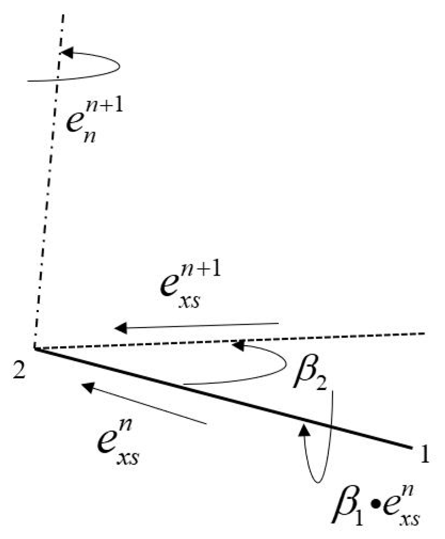
The rotation change in the hose unit from t n to t n + 1 mainly includes the rotation of the unit spindle and the torsion of the spindle itself. As shown in Figure 2, the torsion angle vector of the unit is β 1 , the component of the torsion angle in the spindle is β 1 · e x s n , the torsion vector in the spindle direction is β 1 · e x s n e x s n , the rotation angle of the spindle from t n to t n + 1 is β 2 , the rotation vector is β 2 · e n n + 1 , and the rotation direction e n n + 1 is calculated using the spindle direction vector at time t n and t n + 1 .
The total rotation vector of the element at moments 1 to 2 is as in Equation (3):
γ = β 1 · e x s n e x s n + β 2 · e n n + 1
The rotation of the spindle direction is a spatial variation of the vector. The total rotation vector angle of the spindle and the unit vector of the spindle are as follows:
R γ = I + sin γ A γ + 1 cos γ A γ 2 ,   A γ = 0 n γ m y n γ 0 l γ m y l γ 0
γ = γ ,   e γ = γ γ = l γ     m γ     n γ
where I is a third-order unit diagonal matrix, and R γ is the rotation change matrix.
The adjacent particles of the hose are connected by space beam elements, and the element mass and moment of inertia are integrated into the particles after being equivalent to the nodes at both ends. The mass of the particle includes the concentrated mass and the equivalent mass of the adjacent unit. The moment of inertia of the particle includes the concentrated inertia and the equivalent moment of inertia of the adjacent unit, as shown in Equations (6)–(8) below:
M = m i + j = 1 k m j
I = I i + j = 1 k I j
I j = 1 2 ρ l A r j 2
where m i is the particle concentration quality, I i is the third-order matrix of the concentrated moment of inertia in the global coordinate system, I j is the third-order matrix of the equivalent rotational inertia of adjacent elements in the global coordinate system, r j is the third-order matrix composed of the radius of rotation of the hose section in the global coordinate system, k is number of adjacent units of a particle, ρ is the module density, l is the unit length, and A is a hose cross-sectional area.

2.2. Force Calculation

According to the reverse motion assumption of a vector finite element, it is assumed that the hose element is rotated and translated from time t n + 1 to time t n to obtain the virtual element. According to the deformation increment of the element, the internal force and bending moment of the element are solved according to the traditional mechanics theory. The formula for solving the internal force and bending moment in the principal coordinate system is as in Equation (9):
m ^ x i = m ^ x j = G I ^ x l n θ ^ x j m ^ y i = E I ^ y l n 4 θ ^ y i + 2 θ ^ y j m ^ y j = E I ^ y l n 2 θ ^ y i + 4 θ ^ y j m ^ z i = E I ^ z l n 4 θ ^ z i + 2 θ ^ z j m ^ z j = E I ^ z l n 2 θ ^ z i + 4 θ ^ z j ,   f ^ x i = f ^ x j = E A l n l n + 1 l n f ^ y i = f ^ y j = m ^ z i + m ^ z j l n f ^ z i = f ^ z j = m ^ y i + m ^ y j l n
where m ^ i and m ^ j are the moments of nodes at both ends of element, f ^ i and f ^ j are the internal forces of nodes at both ends of the element, θ ^ i and θ ^ j are increments in the rotation angle of nodes at both ends of the unit, I ^ x , I ^ y , and I ^ z are moments of inertia of the cross-section, E is the elastic modulus, G is the shear modulus, and l n + 1 is the element length at time t n + 1 .
After obtaining the internal force vector and bending moment vector of the element in the principal coordinate system, a forward motion transformation of the element is performed to return it to the moment to obtain the internal force and bending moment in the correct direction. Firstly, the internal force and bending moment of the element in the principal coordinate system are transformed into the global coordinate system, and then the forward rotation transformation is carried out, as shown in Equation (10):
f = f ^ x   f ^ y   f ^ z Ω a n R γ T ,   m = m ^ x   m ^ y   m ^ z Ω a n R γ T
where f and m are the internal force and bending moment of the element node in the global coordinate system at time t n .
After obtaining the internal force and bending moment of each element node of the hose in the global coordinate system, the internal force and bending moment of each node are integrated into the particle. The internal force and bending moment of the particle are a pair of reaction forces with the internal force and bending moment of the node.
The method of applying external force is consistent with that of the internal force. The external force in the global coordinate system is converted to the element principal coordinate system and transformed back to the time moment by reverse rotation. Then, the equivalent external force and equivalent bending moment of the element are obtained according to the traditional finite element theory. The external force of the element node in the time t n + 1 global coordinate system is obtained by coordinate system transformation and forward motion transformation and finally integrated into each particle.
The external forces of deep-sea mining pipelines in water are mainly wave force, buoyancy, and gravity. In the global coordinate system, gravity and buoyancy can be directly applied to each particle, and the wave force is solved according to the Morrison formula, as shown in Equation (11):
f z = ρ w π D 2 4 a w + C a ρ w π D 2 4 a r + 1 2 C D ρ w D v w | v w |
where f z is the wave and current load on the unit height riser at depth z , C a denotes the added mass coefficients, a w is the water point acceleration, a r is the relative acceleration of the water point to the vertical pipe, ρ w is sea water density, D is th eriser diameter, v w is the relative velocity of the water quality point in a vertical pipe, and C D is a drag coefficient.

2.3. Governing Equation

In the three-dimensional problem, there are three translations and three rotations of the hose particle, and the motion of each particle is based on Newton’s second law. The particle control equation is as in Equations (12) and (13):
M i x ¨ i y ¨ i z ¨ i + ζ m M i x ˙ i y ˙ i z ˙ i = f i x i n f i y i n f i z i n + f i x e x f i y e x f i z e x
I i φ ¨ i x φ ¨ i y φ ¨ i z + ζ I I i φ ˙ i x φ ˙ i y φ ˙ i z = m i x i n m i y i n m i z i n + m i x e x m i y e x m i z e x
where f i n , f e x and m i n , m e x are the internal forces and external forces of the particle, φ is the angle of the mass point, I i is the particle moment of the inertia matrix, and ζ m and ζ I denote structural damping.
The central difference scheme is used to discretize the governing equations. After discretization, the governing equations are expressed as Equations (14) and (15):
x i n + 1 y i n + 1 z i n + 1 = 2 C 1 x i n y i n z i n C 2 x i n 1 y i n 1 z i n 1 + C 1 h 2 f x i n f y i n f z i n + f x e x f y e x f z e x / M i
φ i x n + 1 φ i y n + 1 φ i z n + 1 = 2 C 3 φ i x n φ i y n φ i z n C 4 φ i x n 1 φ i y n 1 φ i z n 1 + C 3 h 2 m i x i n m i y i n m i z i n + m i x e x m i y e x m i z e x / I i
where h is the time step, C 1 = 1 / 1 + ζ m h / 2 , C 2 = C 1 / 1 ζ m h / 2 , C 3 = 1 / 1 + ζ I h / 2 , and C 4 = C 3 / 1 ζ I h / 2 .

3. Numerical Calculation and Results

3.1. Verification

Based on the vector form intrinsic finite element theory described above, a MATLAB solution program was developed. In this study, the deep-sea mining hose’s distal end was connected to the mining vehicle, while the proximal end was linked to the relay bin. The mining vehicle operated at a depth of 5100 m, and the relay bin was positioned at a depth of 5000 m. Initially, the mining vehicle was 250 m from the relay bin, and the buoyancy module was distributed along the middle section of the hose, as illustrated in Figure 3. The total analysis duration was 1000 s, with the mining vehicle and relay bin commencing movement at 300 s. Given the considerable water depth of deep-sea mining operations, wave-induced loads on the underwater hose were considered negligible. The relay bin’s motion, influenced by waves, was modeled as simple harmonic motion and incorporated as a boundary condition. The external loads considered included gravity, buoyancy, and steady-state ocean current forces. Deep-sea mining conveyance hoses primarily utilize materials such as high-density polyethylene, aramid fibers, and steel wire braided layers. Through a multi-layer composite structure design, these hoses ensure reliability and durability in the high-pressure, low-temperature, and corrosive environments of the deep sea. Hose and sea state parameters were sourced from the literature [6], as detailed in Table 1.
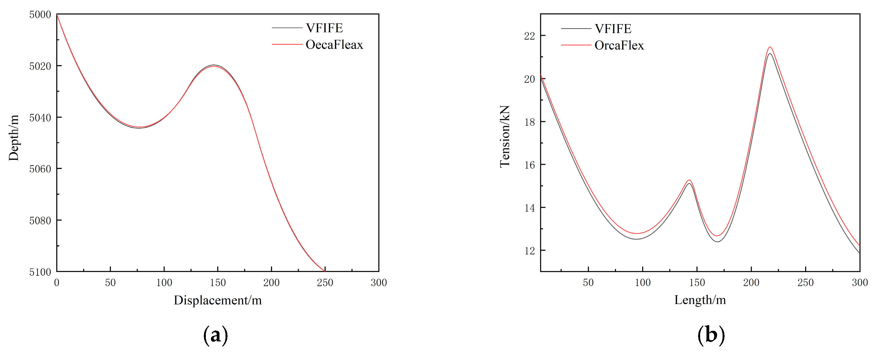
To verify the accuracy and feasibility of the vector form intrinsic finite element method solution program presented in this paper, 12 buoyancy modules were positioned along the hose, spanning a range of 90 m to 156 m from the mining vehicle end. The buoyancy modules were spaced 6 m apart, and both the relay bin and the mining vehicle were assumed to be stationary. The static configuration and internal force distribution of the hose were computed for a current velocity of 0.4 m/s. The results were then compared with those obtained from OrcaFlex, and the static characteristics were analyzed.
As illustrated in Figure 4, the static configuration of the hose calculated using the MATLAB R2023b program based on the vector form intrinsic finite element method and OrcaFlex 10.2 software shows minimal difference in internal force distribution. In Figure 4a, the hose configuration calculated with the vector form intrinsic finite element method exhibits a greater droop value compared to that of OrcaFlex in the 50 m to 100 m droop section, and a larger rise value compared to that of OrcaFlex in the 125 m to 175 m rise section; however, the configurations are largely coincident in other sections. In Figure 4b, the internal force of the hose computed with the vector form intrinsic finite element method is lower than that obtained from OrcaFlex. The internal force at both ends of the buoyancy module section is significant, with the maximum internal force occurring at 220 m along the hose. The vector form intrinsic finite element method yields a maximum force of 21,560 N, while OrcaFlex gives a maximum of 21,862 N, resulting in an error of 1.38%. This discrepancy is primarily due to differences in the models: OrcaFlex employs a lumped mass approach with a spring-damping system to simulate tension, compression, and bending stiffness, using iterative solutions. In contrast, the vector form intrinsic finite element method uses a physical model and simulates the dynamic behavior of the structure via particle trajectories, which does not require iterative approximations, leading to more accurate results that better reflect the actual situation [14].

3.2. Influence of Different Factors

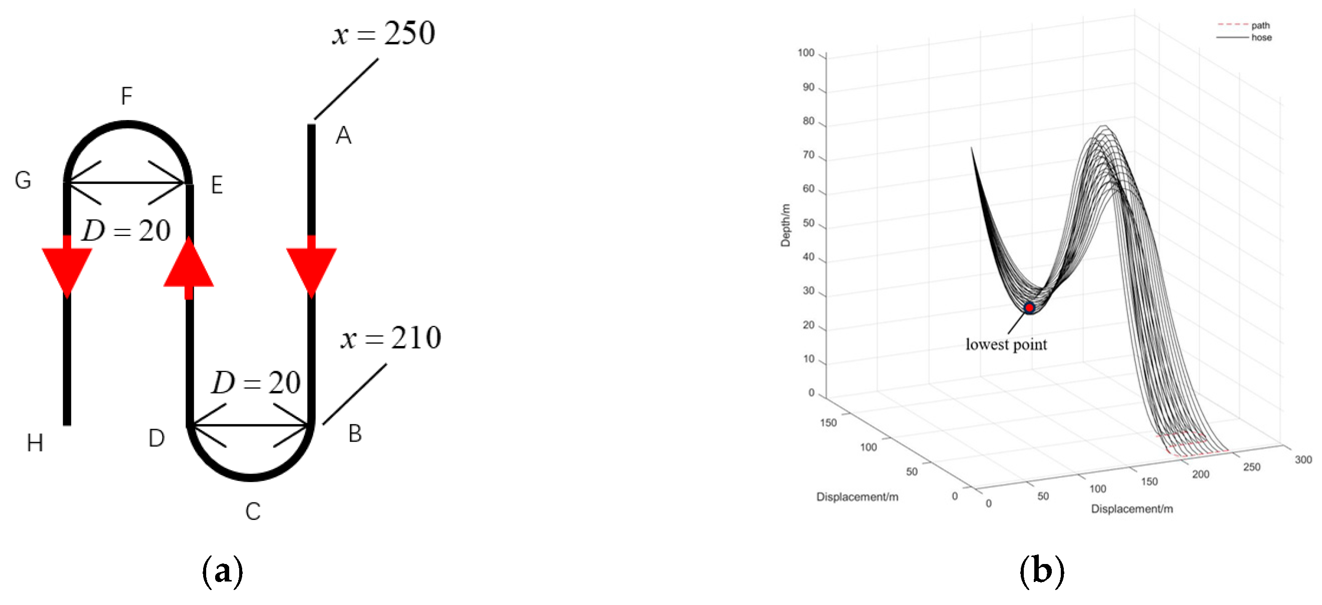
After verifying the feasibility and accuracy of the vector form intrinsic finite element method, based on this method, the influence of the current velocity, the number of buoyancy modules, and the resonance of the intermediate bin on the dynamic response of the hose and the force of the mining vehicle was further studied. The trajectory of the mining vehicle is shown in Figure 5a. The mining vehicle moves from the initial position to the specified position along the path according to the red arrow, and the whole speed of the mining vehicle is kept at 0.2. Figure 5b is the change diagram of the hose configuration during the movement of the mining vehicle, and the lowest point of the arch is taken for analysis. The position is shown in the figure.

3.2.1. Current Velocity

The spacing of the buoyancy modules was set to 6 m, and the relay bin remained stationary. The current velocity was set to 1.0 times, 1.5 times, 2.0 times, and 2.5 times the velocity in Table 1, respectively. The current flowed unidirectionally along the x-axis, and the influence of different current velocities on the force of the structure was analyzed.
Figure 6 shows the dynamic response of the hose at different current speeds. It can be seen from Figure 6a,b that when the mining vehicle moves along paths AC and FH, the hose tension of the relay bin gradually decreases. When moving along path CF, the hose tension of the relay bin gradually increases, and the greater the current speed, the greater the force of the relay bin. When the current velocity is 0.4 m/s to 0.8 m/s, the force of the mining vehicle decreases gradually. When the current velocity is 1.0 m/s, the force of the mining vehicle increases. Therefore, when the current velocity is 0.8 m/s, the force of the mining vehicle is better. When the mining vehicle moves to inflection points C and F, the internal force of the hose fluctuates greatly. The greater the current velocity, the greater the fluctuation amplitude. The maximum fluctuation of the force at the end of the relay bin reaches 28,000 N, and the maximum fluctuation of the force at the end of the mining vehicle reaches 21,000 N, and then the fluctuation decreases. Figure 6c shows the angle between the tension direction of the end head hose of the mining vehicle and the vertical plane. The change in current velocity has a great influence on the force angle of the mining vehicle. It can be seen from the figure that as the current velocity increases, the initial force angle of the mining vehicle becomes smaller, and the angle changes with the movement path of the mining vehicle. When the mining vehicle moves close to the relay bin, the force angle decreases, and when the mining vehicle moves away from the relay bin, the force angle increases. The greater the force angle of the mining vehicle, the more prone it is to roll, which has a negative impact on safe operation. Figure 6d shows the height time history of the lowest point of the hose arch during the movement of the mining vehicle. It can be seen from the figure that the higher the current velocity, the higher the height of the lowest point of the arch. When the current velocity is 0.4, the minimum droop height of the hose appears at point D of the path.

3.2.2. Number of Buoyancy Module

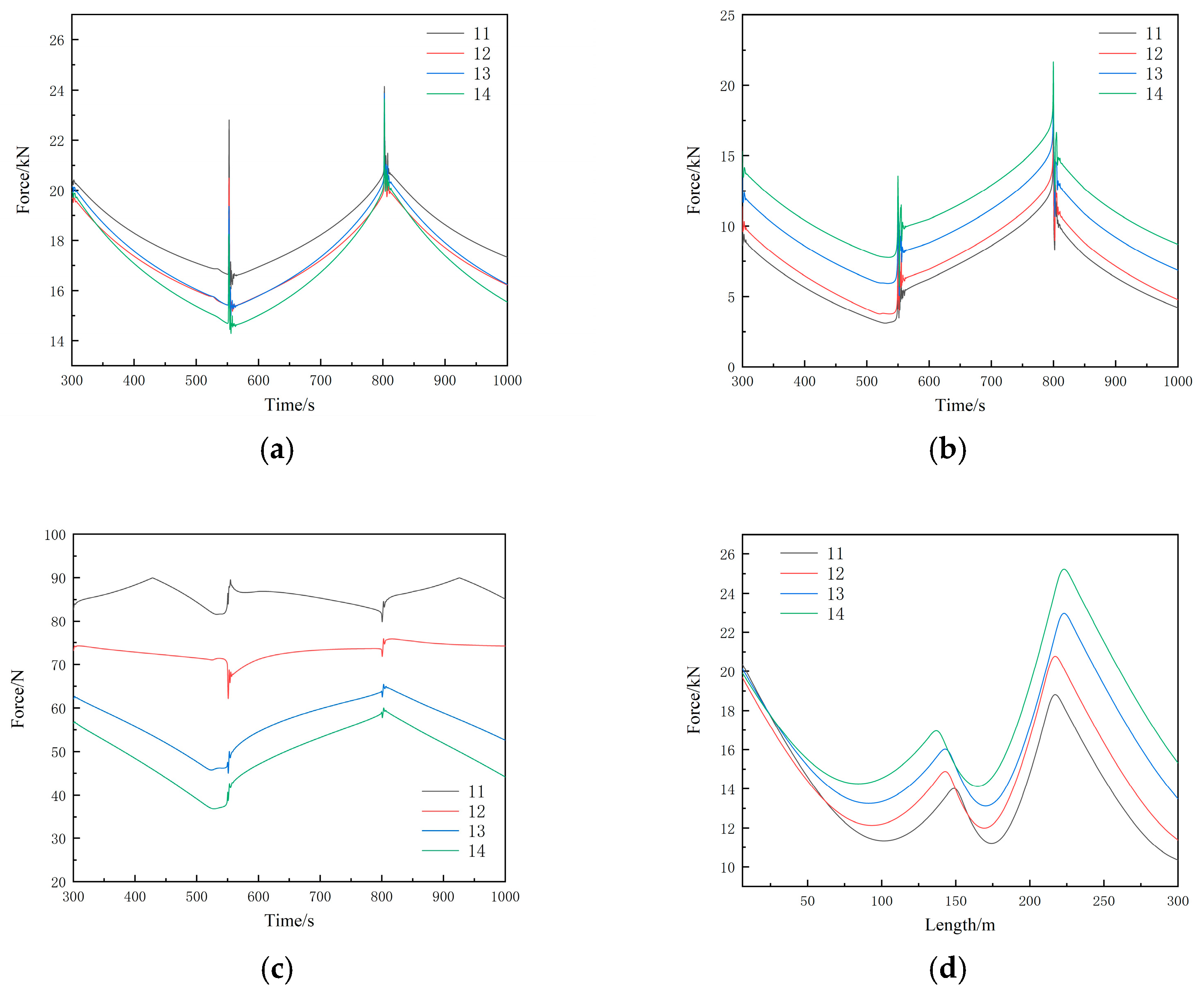
In order to study the influence of the number of buoyancy modules on the hose, the number of buoyancy modules was set to 11, 12, 13, and 14, the spacing of the buoyancy modules was set to 6 m, the current velocity was 0.4 m/s, and the relay bin remained static. The calculation results are shown in Figure 7. It can be seen from the diagram that the number of buoyancy modules has a great influence on the internal force of the hose. With the increase in the number of buoyancy modules, the internal force of the hose at both ends of the buoyancy module increases significantly at the beginning, and the maximum value increases from 19,000 N to 25,000 N. The hose tension of the relay bin decreases, and the force range is between 19,688 N and 20,378 N. The mining vehicle was subjected to hose tension increases. The force variation range is between 9037 N and 14,200 N, and the force angle of the mining vehicle is significantly reduced during the whole process. Therefore, the number of buoyancy modules needs to consider the internal force of the hose at both ends of the buoyancy module section, the tension at the top of the mining vehicle, and the force angle.

3.2.3. Height of Relay Bin

The height of the relay bin significantly affects the spatial configuration of the hose, which, in turn, influences its mechanical properties. The different configurations of the hose will exhibit distinct force distribution characteristics, making the height setting of the relay bin a key factor in the dynamic response analysis of the hose. In this study, the relay bin heights were set at 60 m, 80 m, 100 m, and 120 m. Under the operating condition where the mining vehicle is in motion and the relay bin is stationary, with a unidirectional seawater flow velocity of 0.4 m/s, the mechanical properties of the hose were calculated. The results obtained are presented below.
As shown in Figure 8, the internal forces within the hose generally increase with the height of the relay bin. During the motion of the mining vehicle, the tension at both the relay bin end and the mining vehicle end of the hose increases as the relay bin height increases, which is independent of the mining vehicle’s path, as can be observed from Figure 8a,b. However, the height of the relay bin has a significant impact on the overall internal force distribution of the hose. The internal forces at the hose’s lower arch vary with the height of the relay bin. From Figure 8c, it can be seen that when the relay bin height is 80 m, the internal force at the lower arch of the hose reaches its maximum. As the relay bin height increases, the internal force at this position decreases, while the internal force at the upper arch increases. The primary reason for this is that a higher relay bin height causes the lower arch of the hose to shift to the right, thereby subjecting the bottom end of the relay bin to a greater influence from the hose’s weight. In contrast, a lower relay bin height requires the buoyancy material section to counteract more of the hose’s weight, leading to an increase in the internal force at the left end of the buoyancy material. Therefore, there exists a sensitivity analysis of the relay bin tension and the buoyancy material’s buoyant force, which can be used to identify the optimal solution based on the actual operating conditions.

3.2.4. Pulsating Internal Flow Velocity

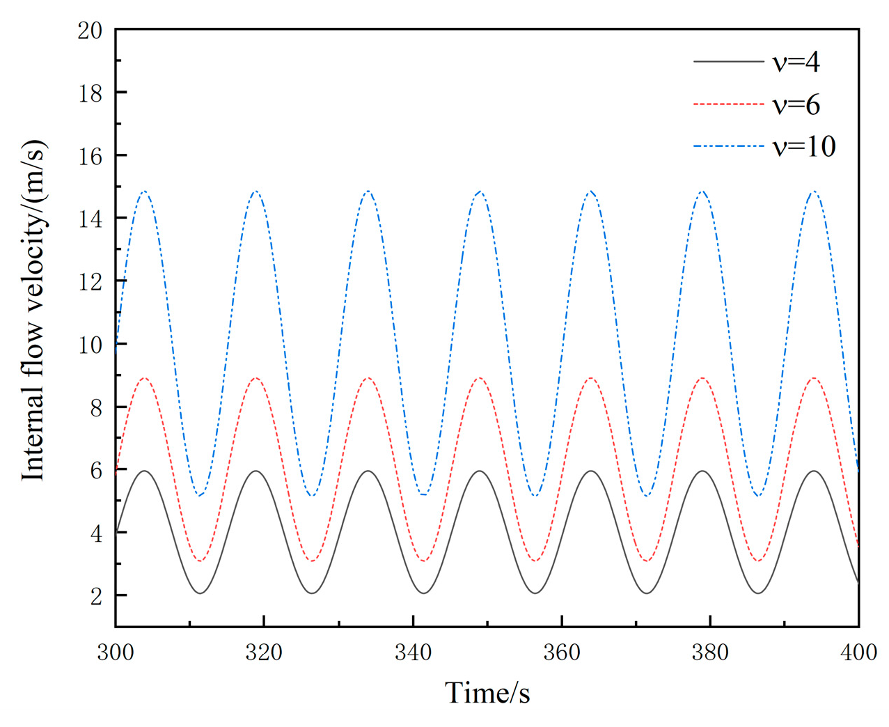
When the mining truck collects metal nodules on the seabed, it will break the metal nodules and transport them to the water surface through the pipeline in the form of slurry. When the internal flow of slurry is transported, the internal flow velocity generally has pulsation characteristics, which is affected by the water level gradient, interface, hose wall friction, gravity, and other factors, resulting in changes in the internal flow velocity. The velocity of the pulsating internal flow can be expressed as U = U 0 1 + μ sin 2 π T 0 t , where U 0 is the initial velocity of the tube inlet, μ is the pulsation coefficient, and T 0 is the pulsation period. Thus, the variation curve of the pulsating flow velocity in the tube can be approximately calculated. The internal flow mainly produces internal friction in the tube, which in turn affects the mechanical properties of the hose. In this study, the initial velocities were set to 0 m/s, 4 m/s, 6 m/s, and 10 m/s, as shown in Figure 9, and the influence of different pulsating internal flow velocities on the dynamic response of the hose was calculated and analyzed.
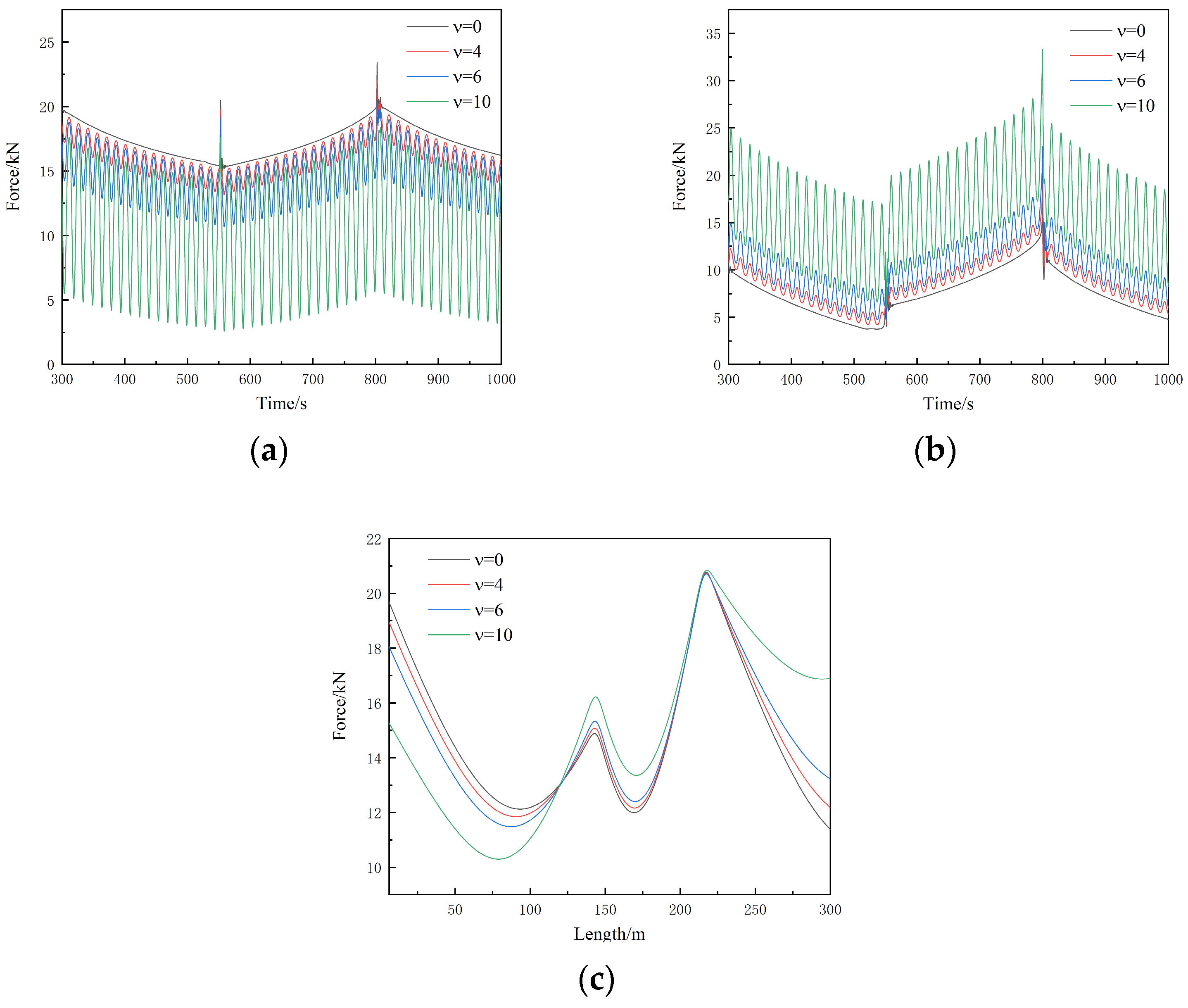
As illustrated in Figure 10a,b, the pulsating internal flow has a significant impact on the forces experienced by both the relay bin and the mining vehicle. The pulsating internal flow reduces the tension in the hose at the relay bin, with the hose tension decreasing as the internal flow velocity increases. Conversely, the tension at the mining vehicle end increases with a higher pulsating internal flow velocity. Both the relay bin and mining vehicle forces exhibit pulsating characteristics similar to those observed in the presence of internal flow, with the amplitude of fluctuations increasing as the initial velocity rises. This dynamic behavior has adverse effects on the hose structure.
From the analysis in Figure 10c, it can be seen that the internal friction generated by the internal flow, combined with the buoyant force provided by the buoyancy material, exerts an upward force on the segment of the hose from the mining vehicle to the upper arch. This increases the internal force in this section of the hose. In contrast, the segment from the upper to the lower arch experiences a downward force due to the combined effect of internal flow friction and the hose’s own weight, resulting in an increased internal force in this region as well. In the section from the relay bin to the lower arch, the gravitational force and internal flow friction counteract each other, reducing the internal force in this part of the hose. These observations validate the phenomenon where the tension at the relay bin decreases while the tension at the mining vehicle end increases.

3.2.5. Movement of Relay Bin

Because the relay bin is connected to the hard pipe, it is affected by the water surface wave of the mining ship, and the relay bin performs an approximately harmonic periodic motion. In order to study the influence of the relay bin motion on the dynamic response of the hose structure, considering the heave and surge motion of the relay bin, the analysis time was 300 s as the initial moment of the relay bin and the mining vehicle motion. The current velocity was set to 0.4 m/s, the number of buoyancy modules was set to 14, the spacing was set to 6 m, the motion period of the relay bin was set to 10 s and 25 s, the heave amplitude was set to 2 m, and the surge amplitude was set to 6.54 m.
Figure 11 is the time history diagram of the force of the hose on the mining truck when the relay bin performs a heave, simple harmonic motion. From Figure 11a, it can be seen that when the relay bin is just performing the simple harmonic motion, the fluctuation of the internal force of the hose will be transmitted to the mining truck. There will be a large fluctuation, and then it tends to be stable. The fluctuation amplitude of the hose force when the period is 10 s is greater than that when the period is 30 s. After the movement of the mining vehicle, the fluctuation amplitude of the hose force gradually decreases along paths AC and FH, and CF gradually increases along the path. When the motion period of the intermediate bin is 25 s, the hose force changes dramatically at inflection points C and F of the path. When the motion period of the intermediate bin is 10 s, the internal force changes little. A possible reason is that when the intermediate bin vibrates at a lower frequency, the internal force of the hose is transmitted slowly along the path and the fluctuation amplitude gradually disappears, and the internal force variability is gradually weakened. Therefore, when the path changes, the internal force changes sharply, and when the intermediate bin vibrates at a higher frequency, the internal force of the hose changes more strongly. Therefore, there is no drastic internal force change at the inflection point of the path.
Figure 12 is the time history diagram of the force of the hose on the mining vehicle when the relay bin is in the simple harmonic motion of the surge. It can be seen from Figure 12a that when the surge frequency of the relay bin is large, the hose force will produce high frequency fluctuation, and the mining vehicle is subjected to the hose force. When the surge frequency of the relay bin is small, the fluctuation of the hose force is more moderate. From Figure 12b, it can be seen that when the mining vehicle moves close to the relay bin, the amplitude of the high-frequency small fluctuations gradually decreases along the path, and the amplitude of the hose force also fluctuates violently at the inflection point of the path when the cycle of the relay bin is 30 s. When the mining vehicle is far away from the relay bin, the amplitude of the fluctuation increases. Therefore, when the mining vehicle moves close to the relay bin, the mining vehicle is under better stress. When the mining vehicle changes the path, the adverse effects of the resonance of the relay bin should be considered, and the high-frequency vibration of the relay bin should be suppressed to reduce the amplitude of internal force fluctuation.

3.2.6. Double-Hose System

Due to the limited time window for deep-sea mining, which is both precious and short, the efficiency of a single collection and transport system is constrained. To improve the efficiency of seabed mineral collection and lifting, multi-hose collection and transport systems are sometimes considered. This paper establishes a double-hose mining vehicle system model based on vector finite elements and conducts a computational analysis of the system’s structural mechanics during the movement of the mining vehicle. The aim is to provide insights and a reference for the future development of multi-hose collection systems.
The material properties of the hoses are consistent with those described earlier. In terms of the initial spatial distribution, Hose 1 is aligned along the x-axis, and Hose 2 is aligned along the y-axis. The relay bin is positioned at the origin of the coordinate system, at a height of 100 m, with both hoses simultaneously connected to the relay bin. The movement path of the mining vehicle connected to the two hoses follows the same trajectory as described previously, with uniform motion starting at the same time at 300 s. The configuration changes in the dual-hose system, as it moves with the mining vehicle, are shown in Figure 13. From the figure, it can be observed that under the influence of unidirectional ocean current along the x-axis, the configuration of Hose 2 shifts slightly toward the x-axis, but no wrinkling or entanglement occurs.
Since the operating conditions of both hoses are identical and both hoses possess the same mechanical characteristics, this paper primarily analyzes the influence of the two hoses on the coupled mechanical behavior of the connected relay bin.
Figure 14 presents a comparison of the force–time histories acting on the relay bin when using two hoses versus a single hose. From the figure, it can be observed that the tension exerted on the relay bin by the two hoses is not twice that of the single hose. The tension increases from 19,000 N to 25,400 N, with a relatively small increment. As the mining vehicle moves, the variation in the tension along the path follows a trend similar to that observed with the single hose. However, at path inflection points C and F, the force fluctuations on the relay bin are less pronounced with the double hoses compared to with the single-hose scenario. This suggests that the internal forces within the two hoses exhibit a mutual suppressive effect, which is beneficial for the stable operation of the relay bin.
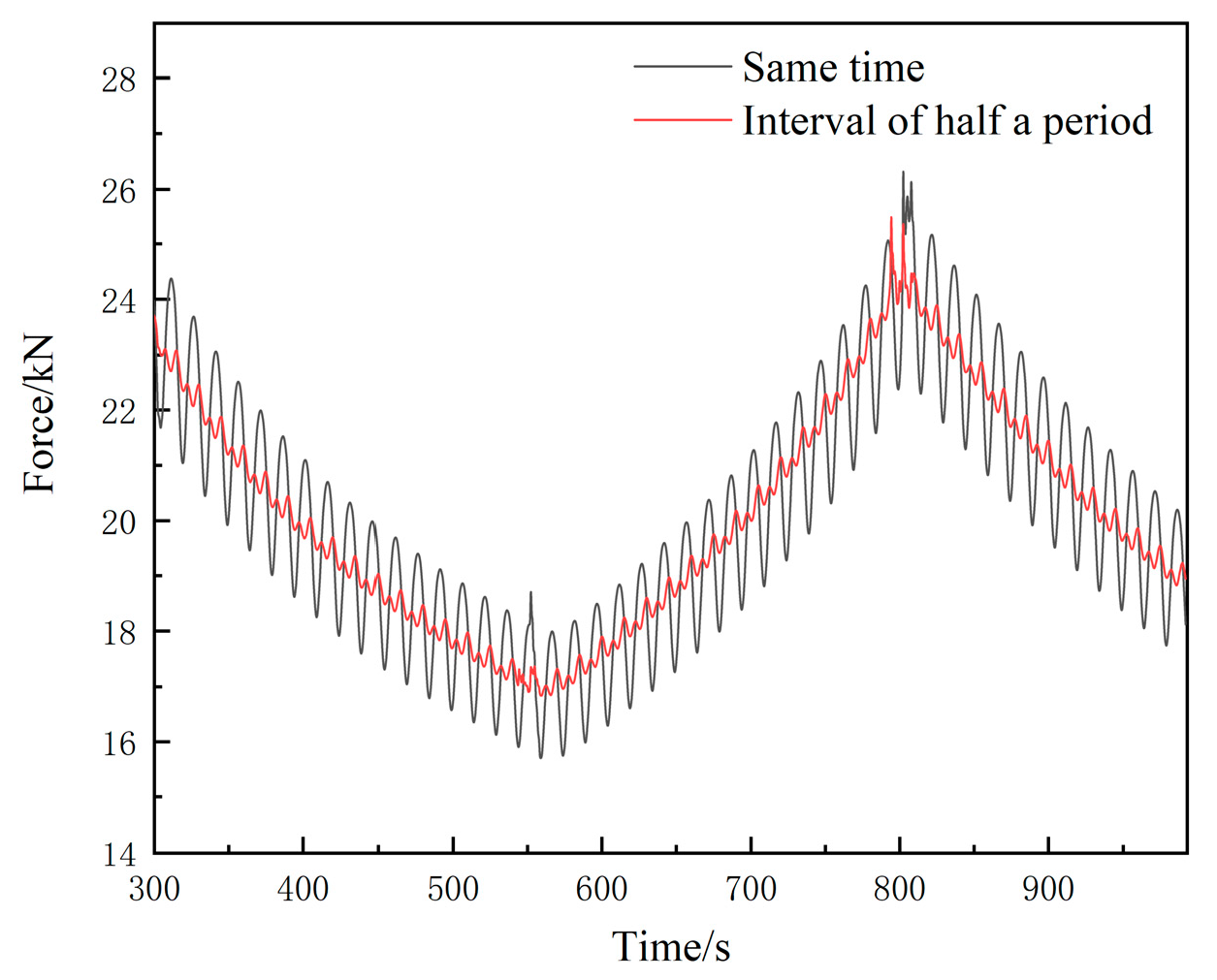
To further analyze the mutual suppressive and canceling effect of the internal forces within the two hoses, a computational analysis was conducted to assess the forces acting on the relay bin when the pulsating internal flow velocity of the two hoses is 4 m/s. The slurry delivery flow of the mining vehicle was configured for two operating conditions: simultaneous flow and flow with a half-period interval between pulsations.
Figure 15 illustrates the impact of the pulsating internal flow in a double-hose system on the forces acting on the relay bin. The figure shows two scenarios: simultaneous slurry delivery from both hoses and slurry delivery from both hoses with a half-pulse period interval. From the figure, it can be observed that when both hoses deliver slurry simultaneously, the forces acting on the relay station are twice those shown in Figure 10a for a single hose, with the fluctuation amplitude also doubling. This results in a detrimental effect on the safe and stable operation of the relay station. In contrast, when the slurry delivery from the two hoses is offset by half a pulse period, the fluctuating forces from both hoses mutually cancel each other out, significantly enhancing the operational stability of the relay station. Therefore, in the case of multi-hose systems, it is crucial to prevent the amplification of adverse factors arising from the operation of multiple hoses.

4. Conclusions

In this study, a deep-sea mining hose model was developed using the vector form intrinsic finite element method. The dynamic response of the hose structure was computed and compared with results from OrcaFlex. The results for the configuration and internal forces, obtained using the vector form intrinsic finite element method and OrcaFlex (which employs the lumped mass method), are in good agreement, demonstrating that the vector form intrinsic finite element method is accurate and feasible for analyzing deep-sea mining hose structures. When assessing the impact of different buoyancy module quantities, current velocities, and pulsating internal flow velocities on the hose, external force conditions in the hose point control equation can be directly modified, and dynamic boundary conditions can be easily applied to the model for dynamic behavior analysis.
When analyzing the dynamic response of the hoses under different motion conditions of the relay bin and mining vehicle, the application of dynamic boundary conditions to the bipartite pipe model allows for a rapid and convenient analysis of the dynamic behavior. For more complex nonlinear systems, such as the double-hose system, vector-based finite element methods can also be utilized for computation and analysis.
This study provides several key findings. Flow velocity significantly impacts the spatial configuration of the hose and increases the force at the relay station end. Increasing the amount of buoyant material reduces the force at the relay station end but raises the internal force at both ends of the buoyant material segment and at the mining vehicle end. Increasing the height of the relay bin decreases the internal force between the buoyant material segment and the relay bin end. The resonant motion of the relay station and pulsating internal flow cause fluctuations in the internal force amplitude, with higher resonance and pulsation frequencies leading to high-frequency small fluctuations that negatively affect the hose structure.
When the mining vehicle moves closer to the relay station, the internal force at both ends of the hose decreases, while moving away increases the internal force. Significant changes in path curvature result in abrupt variations in internal force amplitude. In a dual-hose structure, when two mining vehicles operate with a half-period pulsation cycle, the fluctuation in force amplitude at the relay station is effectively suppressed, promoting the stable operation of the relay station.
Future studies could further explore the dynamic response of deep-sea mining systems involving the coupling of multiple hoses and rigid pipes. In addition, if possible, a VFIFE numerical calculation and experimental comparison analysis should be carried out.

Author Contributions

Writing—original draft preparation, J.X.; writing—review and editing, X.L.; writing—review and editing, H.Z.; methodology, H.Y.; software, M.Z.; investigation, B.W. All authors have read and agreed to the published version of the manuscript.

Funding

This study is supported by the National Key R & D Program (No. 2022YFC2806703), the Shandong Provincial Key R & D Program (No. 2021CXGC010707), and the Hunan Provincial Science and Technology Innovation Program (No. 2022RC3003).

Data Availability Statement

The data that support the findings of this study are available from the corresponding author upon reasonable request.

Conflicts of Interest

Jingchang Xu, Xiaoyan Li, Hao Zheng, Ming Zhang and Bingkun Wang were employed by Changsha Research Institute Mining and Metallurgy Co., Ltd. The remaining authors declare that the research was conducted in the absence of any commercial or financial relationships that could be construed as a potential conflict of interest.

References

  1. Xu, H.H.; Long, G.J. Influence of Mining Vehicle Movement on Sea Mining Flexible Mineral Transporting System. Ocean Eng. 2006, 24, 132–138. [Google Scholar]
  2. Bernitsas, M.M.; Kokarakis, J.E.; Imron, A. Large Deformation Three-dimensional Static Analysis of Deep Water Marine Risers. Appl. Ocean Res. 1985, 7, 178–187. [Google Scholar] [CrossRef]
  3. Zhang, Z.Y. Hydrodynamic Analysis of Marine Flexible Pipe Based on OrcaFlex. China Shiprep. 2024, 37, 54–57. [Google Scholar]
  4. Tong, Y.; Xia, J. Nonlinear Finite Element Simulation of Flexible Riser System in Deep-sea Mining. Chin. J. Comput. Mech. 2022, 39, 129–134. [Google Scholar]
  5. Xu, W.H.; Sha, M.; Wang, Y.Y.; Ma, Y.X. Review on The Mechanical Properties of Flexible Pipe Processing Technology in Deep-sea Mining. Mech. Eng. 2024, 46, 532–547. [Google Scholar]
  6. Song, H.F.; Du, X.G.; Wang, S.; Du, C.Y. Parameter Sensitivity Analysis for Hose Configuration in Deep-Sea Mining Conveying. Shipbuild. China 2020, 61, 154–163. [Google Scholar]
  7. Yu, Y.; Li, Z.M. Vector Form Finite Element and Its Application in Ocean Engineering; Tianjin University Press: Tianjin, China, 2022; pp. 20–46. [Google Scholar]
  8. Gu, H.Y. Research on Dynamic Response and Fatigue Damage of Deep-Sea Catenary Riser Based on Vector Form Intrinsic Finite Element. Master’s Thesis, Fuzhou University, Fuzhou, China, 2021. [Google Scholar]
  9. Yu, Y.; Liu, X.W.; Li, Z.M. Dynamic Characteristics of Lazy Wave Risers under Internal Solitary Waves. J. Ship Mech. 2024, 28, 803–817. [Google Scholar]
  10. Liu, D.C.; Li, X.M.; Guo, H.Y.; Li, F.H. Influence of Hydro-Pneumatic Tensioner on Static and Dynamic Response of Top Tensioned Riser. Period. Ocean. Univ. China 2023, 53, 161–170. [Google Scholar]
  11. Li, X.M.; Guo, X.L.; Guo, H.Y. Vector Form Intrinsic Finite Element Method for the Two-dimensional Analysis of Marine Risers with Large Deformations. J. Ocean Univ. China 2018, 17, 498–506. [Google Scholar] [CrossRef]
  12. Li, X.M.; Guo, X.L.; Guo, H.Y. Vector Form Intrinsic Finite Element Method for Nonlinear Analysis of Three-dimensional Marine Risers. Ocean Eng. 2018, 161, 257–267. [Google Scholar] [CrossRef]
  13. Chen, D.P.; Gu, H.L.; Li, F.H.; Li, X.M.; Guo, H.Y. Study on Vortex-induced Vibration Characteristics of Catenary Type Riser under Oscillatory Flow. J. Ship Mech. 2022, 26, 1227–1236. [Google Scholar]
  14. Li, X.M.; Zhang, L.; Niu, J.J.; Han, Y.Q.; Guo, H.Y. Dynamic Response of A Deep-sea Top Tensioned Riser Based on Vector Form Intrinsic Finite Element. J. Vib. Shock. 2016, 35, 218–223. [Google Scholar]
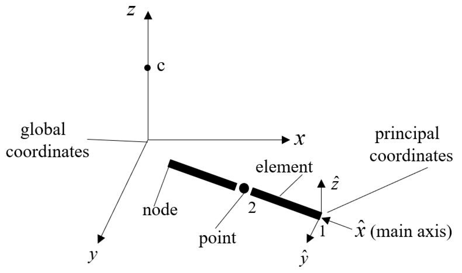
Figure 1. Coordinate system and unit connection.
Jmse 13 00701 g001
Figure 2. Unit rotation.
Jmse 13 00701 g002
Figure 3. Deep-sea mining hose structure diagram.
Jmse 13 00701 g003
Figure 4. Comparison of VFIFE and OrcaFlex results. (a) Configuration comparison diagram; (b) comparison diagram of internal force distribution.
Jmse 13 00701 g004
Figure 5. Mining vehicle path and hose motion. (a) Motion path; (b) hose configuration.
Jmse 13 00701 g005
Figure 6. Dynamic response of the hose with different current velocities. (a) Force on the relay bin; (b) force on the mining vehicle; (c) force angle of the mining vehicle; (d) static internal force distribution of hoses.
Jmse 13 00701 g006
Figure 7. Response of hose structure with different numbers of buoyancy modules. (a) Force on the relay bin; (b) force on the mining vehicle; (c) force angle of the mining vehicle; (d) static internal force distribution of hoses.
Jmse 13 00701 g007
Figure 8. Dynamic response of the hose with relay bins of different heights. (a) Force on the relay bin; (b) force on the mining vehicle; (c) static internal force distribution of hoses.
Jmse 13 00701 g008
Figure 9. Pulsating internal flow velocity.
Jmse 13 00701 g009
Figure 10. Dynamic response of the hose with different pulsating internal flow velocities. (a) Force on the relay bin; (b) force on the mining vehicle; (c) static internal force distribution of hoses.
Jmse 13 00701 g010
Figure 11. Hose force acting on mining vehicles with different heave periods in relay bin. (a) When the mining vehicle is stationary; (b) when the mining vehicle is moving.
Jmse 13 00701 g011
Figure 12. Hose forces acting on mining vehicles with different surge periods in relay bin. (a) When the mining vehicle is stationary; (b) when the mining vehicle is moving.
Jmse 13 00701 g012
Figure 13. Double-hose configuration linkage change diagram. (a) Side view; (b) vertical view.
Jmse 13 00701 g013
Figure 14. Dynamic response of double-hose system.
Jmse 13 00701 g014
Figure 15. Dynamic response of double-hose internal flow.
Jmse 13 00701 g015
Table 1. Deep-sea mining hose parameters.
ParametersValueUnit
length300m
outside diameter0.263m
inner diameters0.200m
modulus0.05GPa
dry weight of unit hose38.4kg
inflow mass density1133kg/m3
buoyancy of one floating module3312.4N
water velocity0.4m/s
water density1025kg/m3
drag coefficient1.2
Disclaimer/Publisher’s Note: The statements, opinions and data contained in all publications are solely those of the individual author(s) and contributor(s) and not of MDPI and/or the editor(s). MDPI and/or the editor(s) disclaim responsibility for any injury to people or property resulting from any ideas, methods, instructions or products referred to in the content.