Article

Comparative Study on Wave Elevations Downstream of Monopile- and Jacket-Mounted Offshore Wind Turbines

by
Sharath Srinivasamurthy
1,*,
Shigeo Yoshida
1,2 and
Shotaro Watanabe
3
1
Institute of Ocean Energy, Saga University, Saga 840-8502, Japan
2
Research Institute for Applied Mechanics, Kyushu University, Kasuga 816-8580, Japan
3
ENEOS Renewable Energy Corporation, Tokyo 106-0032, Japan
*
Author to whom correspondence should be addressed.
J. Mar. Sci. Eng. 2025, 13(4), 661; https://doi.org/10.3390/jmse13040661
Submission received: 25 February 2025 / Revised: 19 March 2025 / Accepted: 24 March 2025 / Published: 26 March 2025
(This article belongs to the Special Issue Innovative Development of Offshore Wind Technology)

Abstract

:
Offshore wind turbines, especially the fixed-bottom type, have been commercialized and installed in recent years. Generally, an offshore sub-structure such as a monopile or a jacket foundation is adopted to secure offshore wind turbines. There have been concerns raised by surfers regarding the reduction in wave elevations downstream due to the installation of offshore sub-structures in the sea. This study is therefore dedicated to understanding the near-field and far-field wave effects of fixed-bottom foundations. To this end, 1.6% scale models of a (i) monopile foundation and (ii) jacket foundation were crafted, and near-field wave elevations downstream of the model were measured in a water tank under regular waves. A calculation method based on linear potential theory was implemented and validated with the experimental results. The calculated far-field wave elevations downstream of the monopile and jacket foundations were then analyzed for a range of wave periods and wave profiles were plotted at various distances from the foundations. It was found that the effect of monopile foundations on wave elevation was limited except around the edges of the foundation. Further, the wave elevation reduction was minimal at less than 1% at a distance of 750 m or more and less than 0.7% at a distance of more than 2000 m from the monopile foundation. The jacket foundations had no effect on the wave elevation downstream.

1. Introduction

Japan has set an ambitious goal for carbon neutrality by 2050, aiming to reduce its greenhouse gas emissions to net zero [1]. This target is a key part of Japan’s efforts to combat climate change and transition to a more sustainable future [2]. Japan has also committed to reducing its greenhouse gas emissions by 46% by 2030 [3], compared to 2013 levels, and aiming for a 50% reduction by 2030. To achieve this, Japan has been gradually increasing its use of clean energy [4], and the Green Growth Strategy is being implemented [5]. It plans to boost the share of renewables in its energy mix to around 50–60% by 2050.
Offshore wind energy is one of the fastest growing renewable energy sources globally. Japan also looks at offshore wind due to its high potential and aims to achieve a capacity of about 10 GW by 2030 and 30–45 GW by 2040 [6]. Offshore wind energy can be mainly divided into two types, the fixed-bottom type and the floating type. The floating type is an emerging technology and feasibility tests are ongoing for practical applications. However, the fixed-bottom type of offshore wind technology is well established, and its commercialization is underway. Further, the fixed-bottom type is cost-effective since it is installed relatively closer to the coast and can be built using currently available construction technology. The Kitakyushu Hibikinada Offshore Wind Farm Project is under implementation and consists of 25 large wind turbines with a unit capacity of 9.6 MW [7]. The jacket-type fixed-bottom foundation is expected to support the wind turbines and it will be the largest offshore wind farm in Japan upon its completion in terms of the generating output.
Offshore wind energy provides a good solution to achieve carbon neutrality but there are other challenges and concerns. One of the concerns raised by surfers and local communities is the potential reduction in wave height due to the presence of fixed-bottom foundations. There have also been concerns about how it will impact surfing regions on the coast if offshore wind farms are installed by coastal communities in Karatsu, Japan [8], Waimānalo, HI, USA [9], and Illawarra, Australia [10]. As shown in Figure 1, the preferred wave height and minimum surfable height varies depending on the expertise level of the surfers [11]. The minimum surfable wave height for beginners is close to 60 cm, and it comes down to 35 cm for professional surfers. Therefore, addressing the effect of fixed-bottom foundations on downstream wave height is essential to have a consensus with surfers, local communities, and other stakeholders.
A number of studies have been conducted on hydrodynamic loads on offshore monopile [12] and jacket structures [13]. The dynamic response of fixed-bottom wind turbines in waves has also been studied [14,15,16], both experimentally and numerically. However, there are limited studies related to addressing wave effect phenomena and almost no studies to understand the wave elevations downstream of fixed-bottom foundations. The present study aims to address and overcome this concern by understanding wave effect phenomena downstream of fixed-bottom foundations.
The Centre for Environment, Fisheries and Aquaculture Science (CEFAS), UK, created the first project report [17] on the impact of the construction of the Scroby Sands offshore wind farms. This analysis found a 3–5% reduction in wave height due to wave diffraction by the offshore wind farms and concluded that the impacts on wave regimes were not significant. An attempt to simulate wave damping near the coast due to offshore wind farms in Estonia was conducted using the Simulating Waves Nearshore (SWAN) model [18]. The study concluded that the diffraction and refraction were small and there was less than a 1% reduction in the significant wave height. However, both the CEFAS and SWAN studies were limited to simulation and wave modeling, without any model-scale experiments. Further, both studies considered monopiles in the research and did not consider different types of fixed-bottom foundations. The variation in wave elevation with the distance from the foundations was also not included. It is essential to overcome these limitations.
A few studies have been conducted to understand the impact of offshore wind farms on sea states, demonstrated by airborne LiDAR measurements [19]. The influence of offshore wind farms on surface waves [20] and their impact on shoreline development have also been studied [21]. There are studies related to pile–pile mutual interactions [22], and there is research on the seismic response of pile groups [23]. Further, diffraction studies due to circular cylinders have been conducted to understand near-field wave elevations around floating structures [24,25]. A study on a fundamental coupling methodology for modeling the near-field and far-field wave effects of floating structures was proposed in [26], and wave damping on floating platforms has been extensively studied [27,28]. However, fixed-bottom foundations such as monopile and jacket structures are different from floating structures, and there needs to be a dedicated study for near-field and far-field wave elevations downstream.
Therefore, the purpose of this study is firstly to understand near-field wave elevations around fixed-bottom foundations. To this end, in this research, two models of fixed-bottom foundations, (i) monopile and (ii) jacket ones, were designed and crafted. The models were then tested under regular waves in a water tank, and the near-field wave elevation was measured. The second objective of this study is to propose a calculation methodology and validate the calculation method. And then, the final objective is to understand the far-field wave elevations of both monopile and jacket foundations. With this approach, it is possible to have a sound technical background to help address the concerns of surfers, offshore wind power companies, and policymakers.
This paper is organized as follows. Section 2 describes the experimental details of the monopile and jacket models. It describes the principal particulars of the models, along with the experimental setup and procedure. Section 3 exemplifies the proposed calculation methodology. Section 4 validates the proposed calculation method with model-scale measurements. It also discusses the far-field wave elevations downstream of the monopile and jacket foundations. The findings of this study are concluded in Section 5.

2. Experimental Models

In this study, two model-scale experimental models, (i) a monopile foundation and (ii) a jacket foundation, are considered. This section describes the details of the model-scale experimental models, the experimental setup, and the experimental conditions. It is further noted that geometric similarity was maintained using Froude scaling for the experimental models.

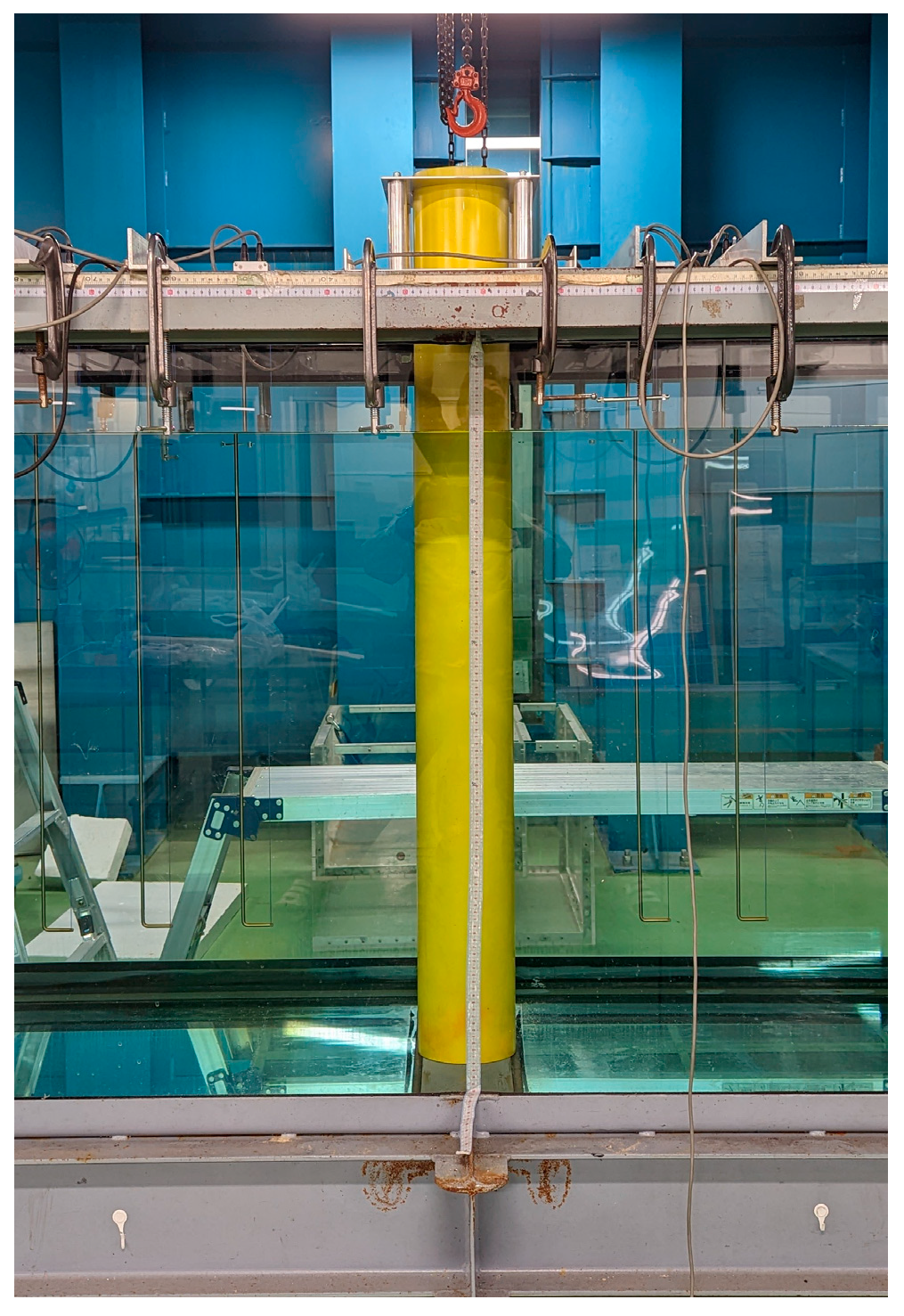
2.1. Monopile Foundation

Figure 2 shows the monopile foundation in the wave tank used in the model-scale experiment. A 1.6% scale model was crafted and chosen for the experiment to suit the two-dimensional wave tank facility at the Institute of Ocean Energy, Saga University, Japan. All tests were conducted in this wave tank, which measured 18.1 m in length, 0.8 m in width, and 1.0 m in depth. The monopile consisted of a cylindrical structure with a diameter of 0.16 m (10 m at full scale).
Table 1 exemplifies the principal particulars of the monopile foundation. The foundation is designed to host the IEA Wind 15-MW reference turbine [29] at water depths of 20–60 m. Since the water depth of the wave tank was 1.0 m, the experiment reflected a water depth of about 62.5 m at a full scale.

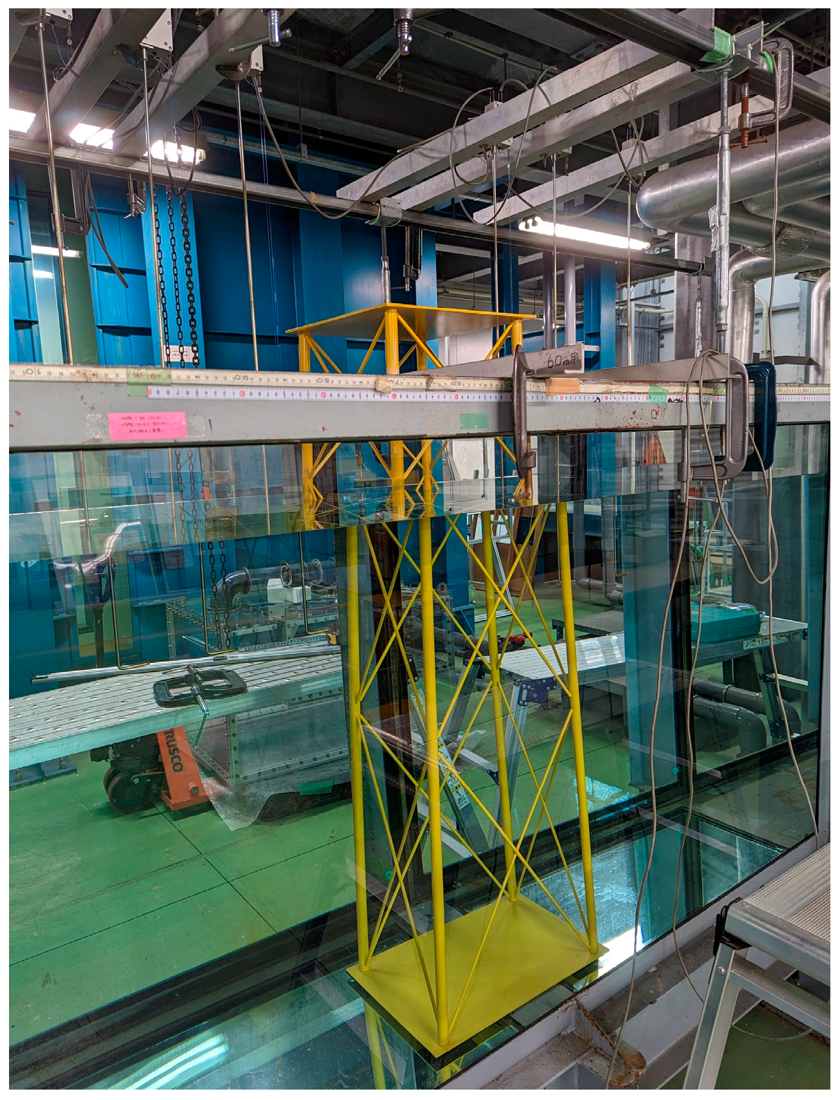
2.2. Jacket Foundation

Figure 3 shows the crafted scaled jacket foundation model in the wave tank. The jacket foundation consists of the main structure, braces connecting the main structure, a base plate, and a deck plate.
Table 2 summarizes the dimensions of the jacket foundation. As in the case of the monopile foundation, the jacket foundation is also designed to host the IEA 15-MW reference turbine. The diameter of the main structure and braces is 0.023 m (1.4 m at full scale) and 0.007 m (0.4 m at full scale), respectively. The base width is 0.416 m (26.0 m in full scale) and the deck width is 0.32 m (20.0 m at full scale).

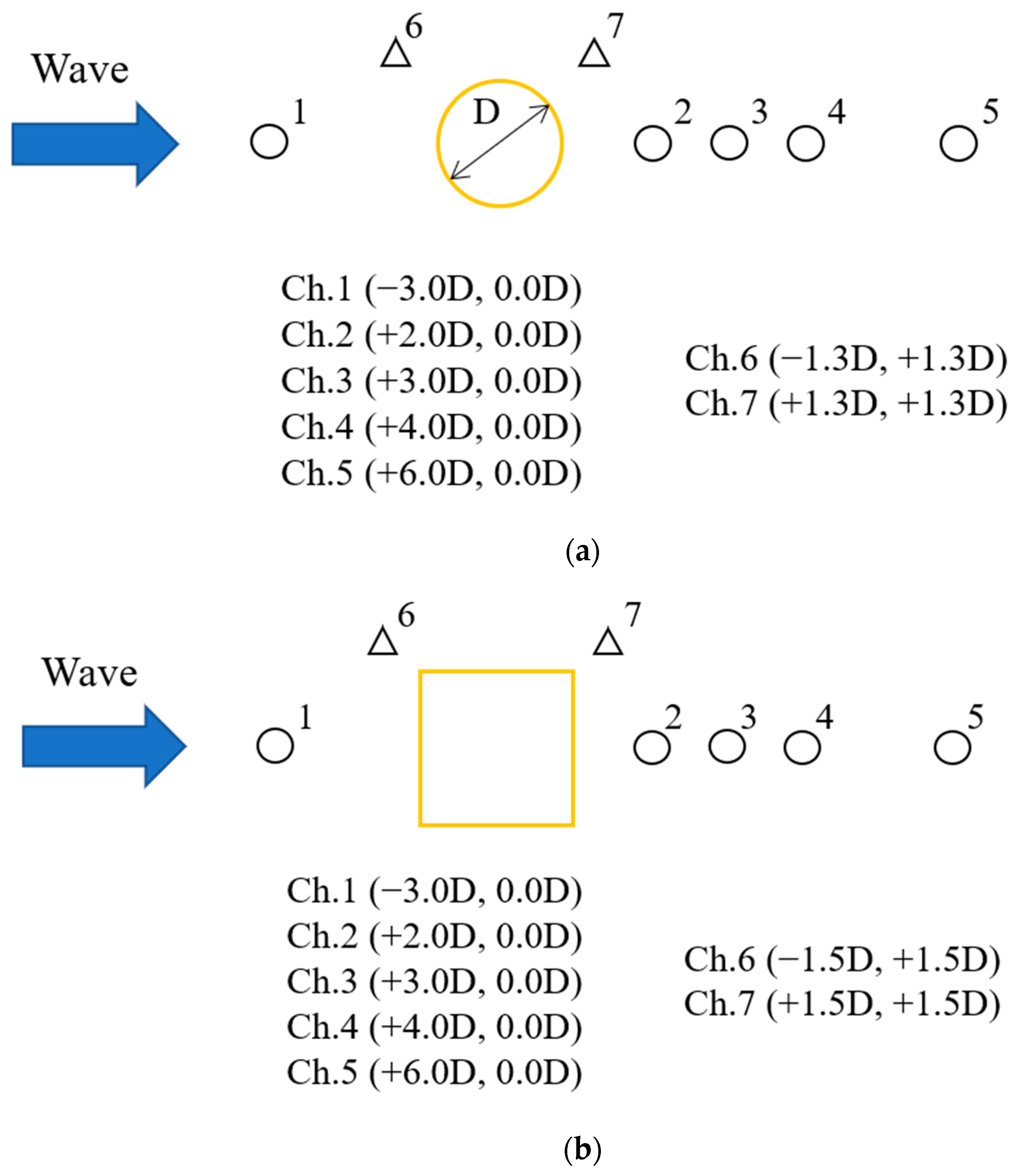
2.3. Experimental Setup and Procedure

The crafted models were tested under waves by placing them in the center of the wave tank and measuring the near-field wave elevations at seven locations. Figure 4 shows the top view of the wave measurement sensor locations and the distance between the channels. Five channels of measurement sensors were placed in the center line, one upstream (Ch.1) and four downstream (Ch.2 to Ch.5) of the monopile and jacket foundations. Ch.6 (upstream of the foundation) and Ch.7 (downstream of the foundation) were placed obliquely from the foundations to measure the wave elevation at the side of the foundations. They were placed at a distance of 1.3D for the monopile foundation and a 1.5D distance for the jacket foundation. It is noted here that D is the diameter of the monopile foundation.
Table 3 summarizes all the experimental conditions of the wave tests. Based on the Froude scaling law, the parameter for wave period scales with S , and wave height scales with S , where S is the scaling factor. Therefore, a wave period of 0.8 s at the model scale corresponds to 0.8 62.5 = 6.3 s at the full scale. The wave period range of the wave tank was 0.8 to 2.5 s (which corresponded to 6.3 to 16.6 s at full scale) and wave heights of 0.02, 0.04, and 0.06 m (which corresponded to 1.25 to 3.75 m at full scale) were considered in the model-scale experiments. Since the objective of the present study was to understand the wave elevations downstream of the foundations, the relative wave elevation due to the incoming waves was obtained for the monopile and jacket foundations. The relative wave elevation could be defined as the wave elevation measured at the channel relative to the wave elevation at the center of the foundation.

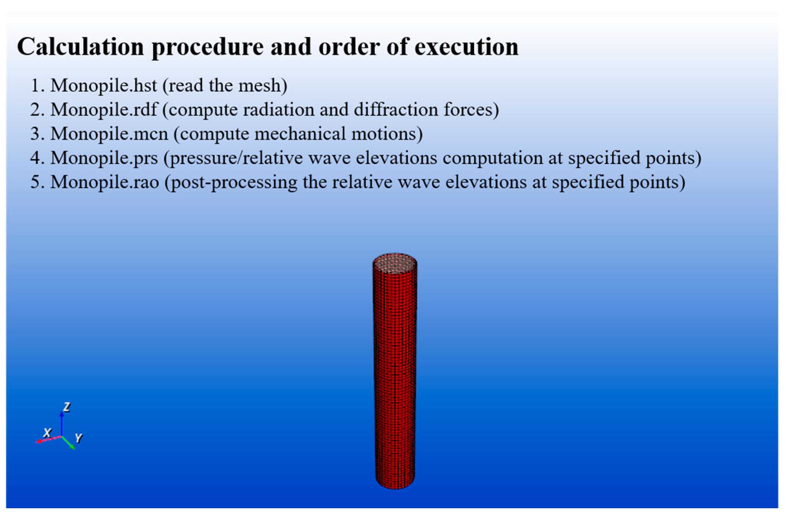
3. Calculation Methodology

The fixed-bottom foundations diffracted and refracted the incoming waves, and it was important to capture their interaction in the calculation. Therefore, in this study, a powerful 3D diffraction/radiation software based on potential theory for wave–body interactions called HydroStar (Version 8.2.1) [30] was utilized. Even though the software is for floating platforms, it was possible to utilize it for fixed-bottom foundations as the main objective of this study is to understand near-field and far-field wave elevations.
The calculation methodology firstly involved creating a surface mesh of the foundation in Rhino 7 [31]. Secondly, the surface mesh was read into the HydroStar working environment for calculations. Figure 5 shows an example of the calculation procedure carried out in HydroStar. After reading the mesh into the software, radiation and diffraction forces were computed. Then, it was important to consider the motion response of the foundation and verify that the motion of the foundations was nil or very close to zero. The procedure was carried out for different surface meshes and a mesh convergence study was carried out.
After understanding and verifying that the motion response of the foundation was close to zero, the pressure or relative wave elevations were computed at specified points or locations. The results obtained were then post-processed such that the relative wave elevations could be obtained both upstream and downstream of the foundation as defined and set up in the model-scale experiment. With this procedure, it was also possible to obtain far-field wave elevations.

4. Results and Discussion

In this section, the results of this study are divided into three parts. Firstly, the motion response of monopile and jacket foundations are summarized in Section 4.1. The second part (Section 4.2) is to validate the calculations by comparing them with the model-scale experiment results. In the end, the far-field wave elevations are calculated for both the monopile and jacket foundations and compared in Section 4.3.

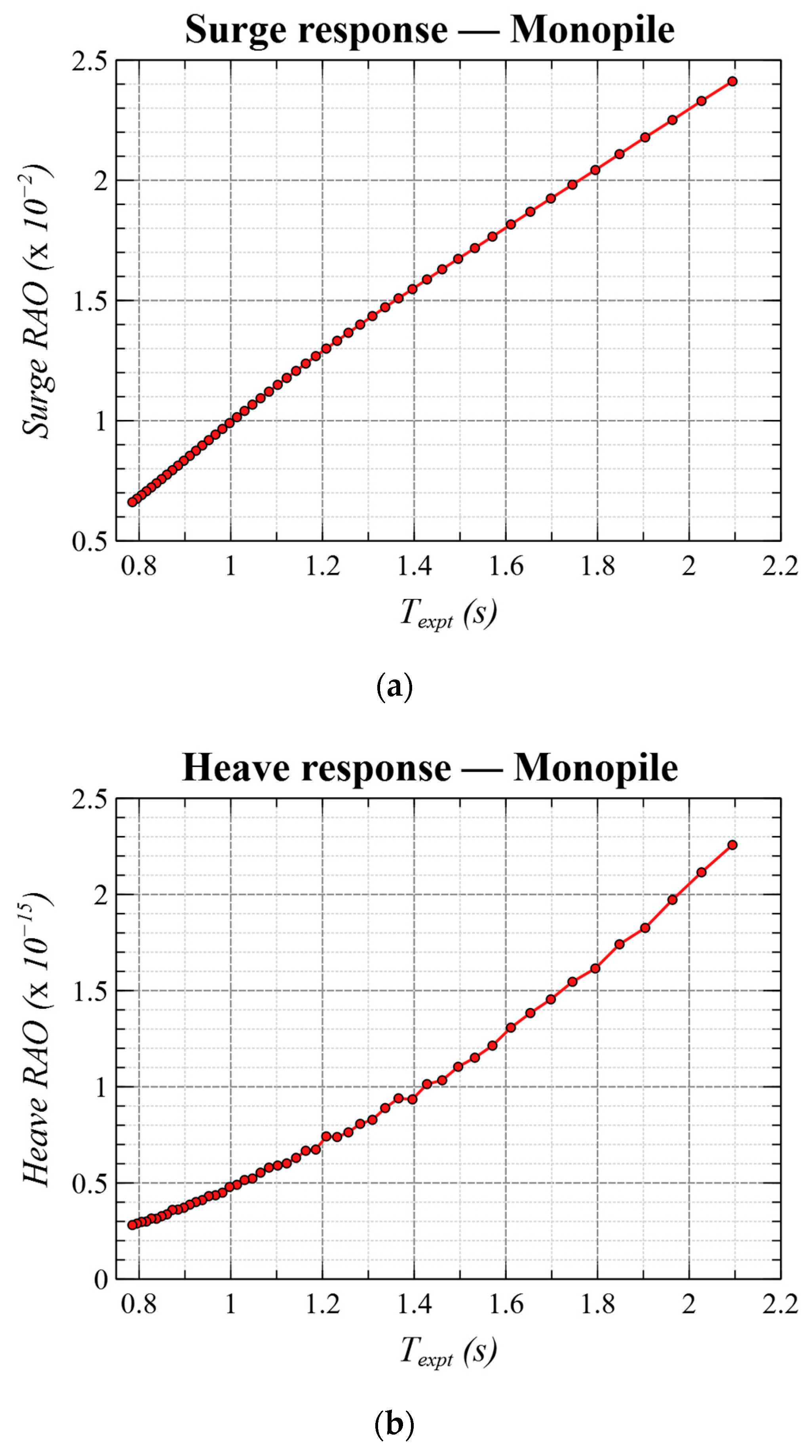
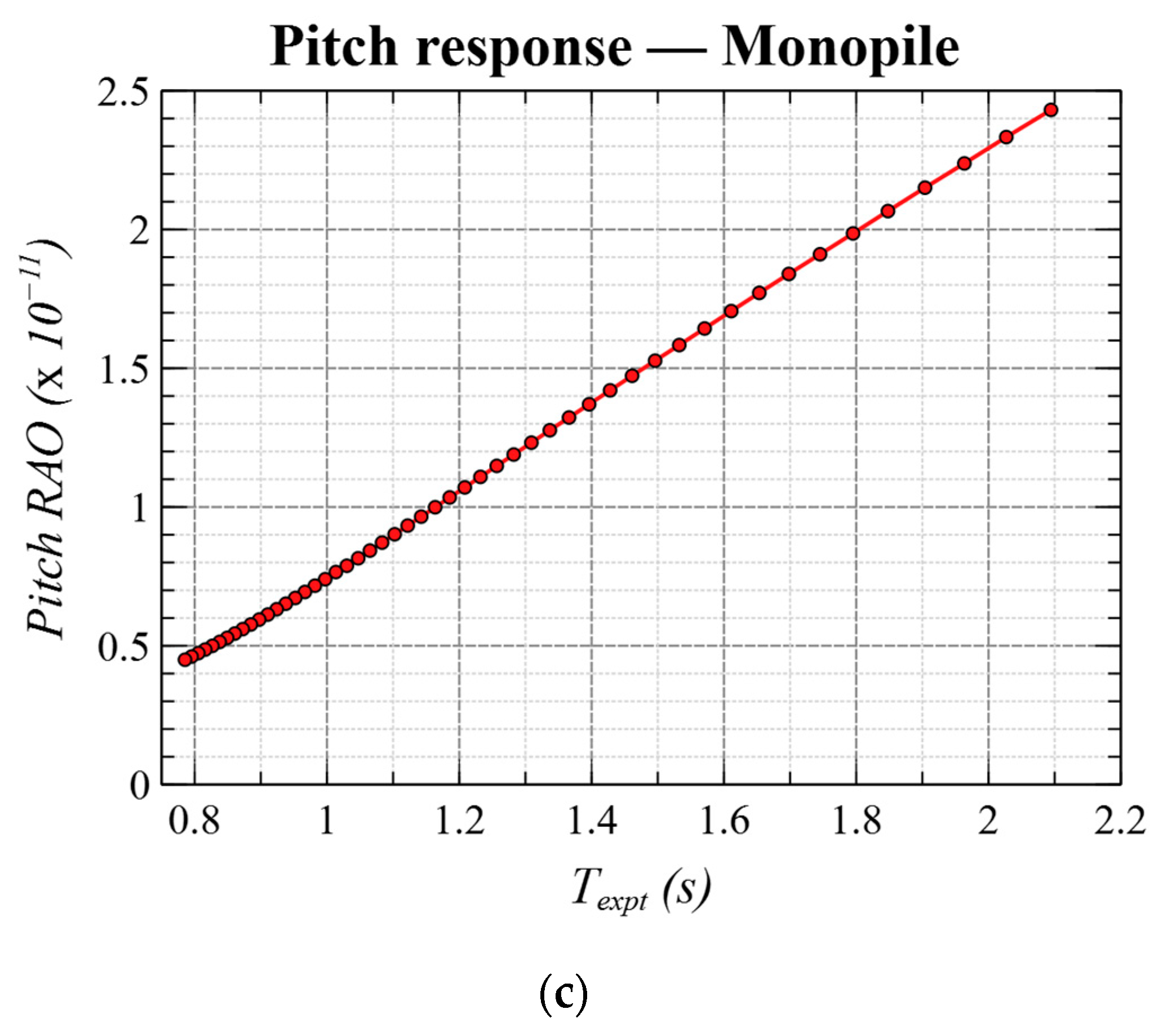
4.1. Motion Response of Foundations

In this section, the motion response of the monopile and jacket foundations under waves are summarized in the surge, heave, and pitch directions. The calculations were conducted based on the principal particulars of the scaled experimental models reflecting the experimental conditions. In reality, we aimed to have a fixed foundation for the stable production of electricity and structural behavior was understood under various loading conditions. However, in this study, the wave was considered the main load and the response of the structure was obtained for a range of incoming waves.
Figure 6 and Figure 7 show the motion response of the monopile and the jacket foundations, respectively. The heave and pitch motion response of the monopile foundation (see Figure 6b,c) was found to be extremely small (in the magnitude order of 10−15 and 10−11, respectively). Further, the surge motion response was also found to be small (in the magnitude order of 10−2) for a range of wave periods. It can be deduced that the monopile foundation motion was extremely small and is considered fixed. From Figure 7, the surge, heave, and pitch motion response of the jacket foundation are found to be small, in the magnitude order of 10−4, 10−4, and 10−2, respectively. It can be verified that the motion of the jacket foundation was also negligible and can be considered fixed.

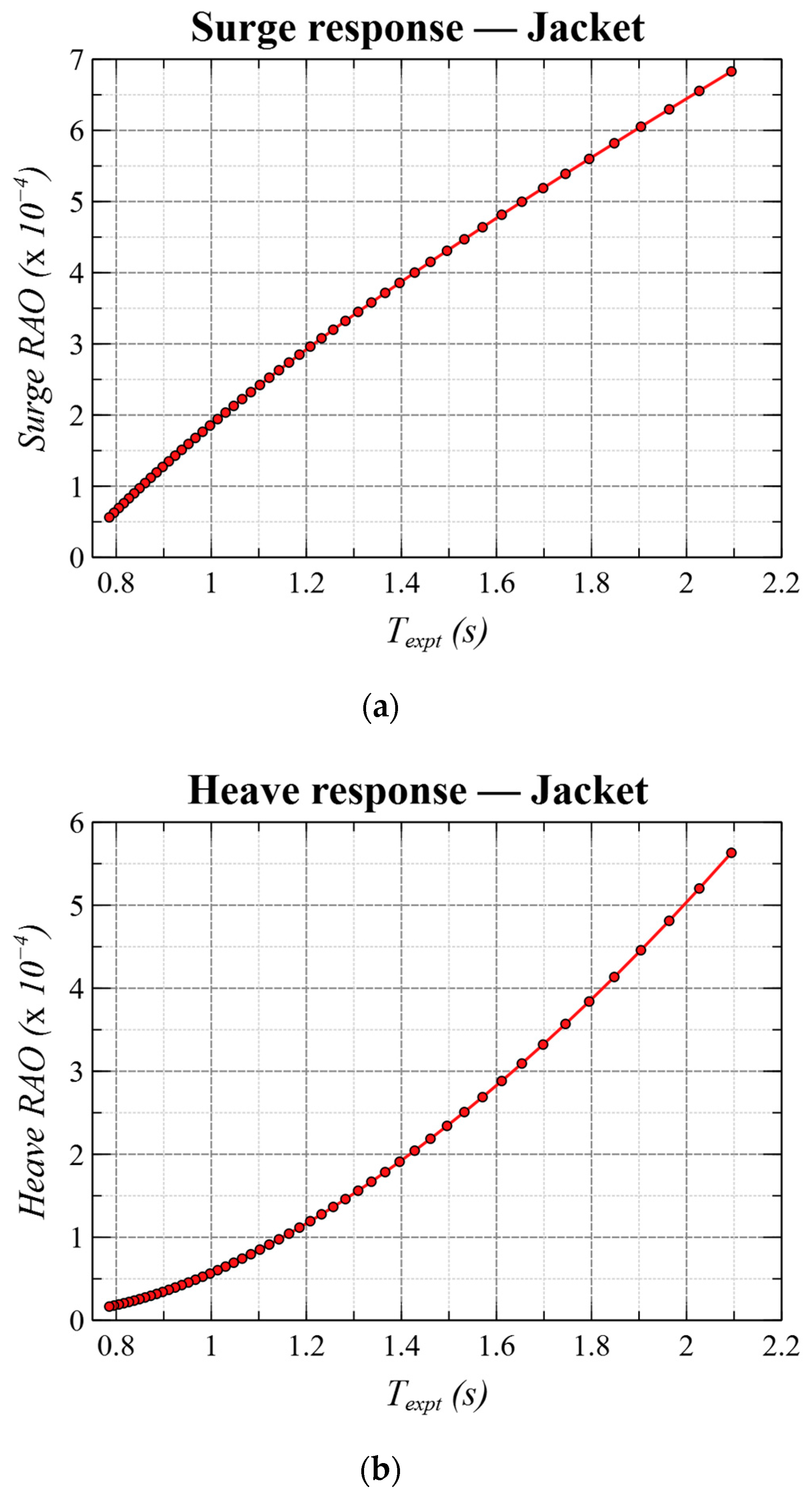
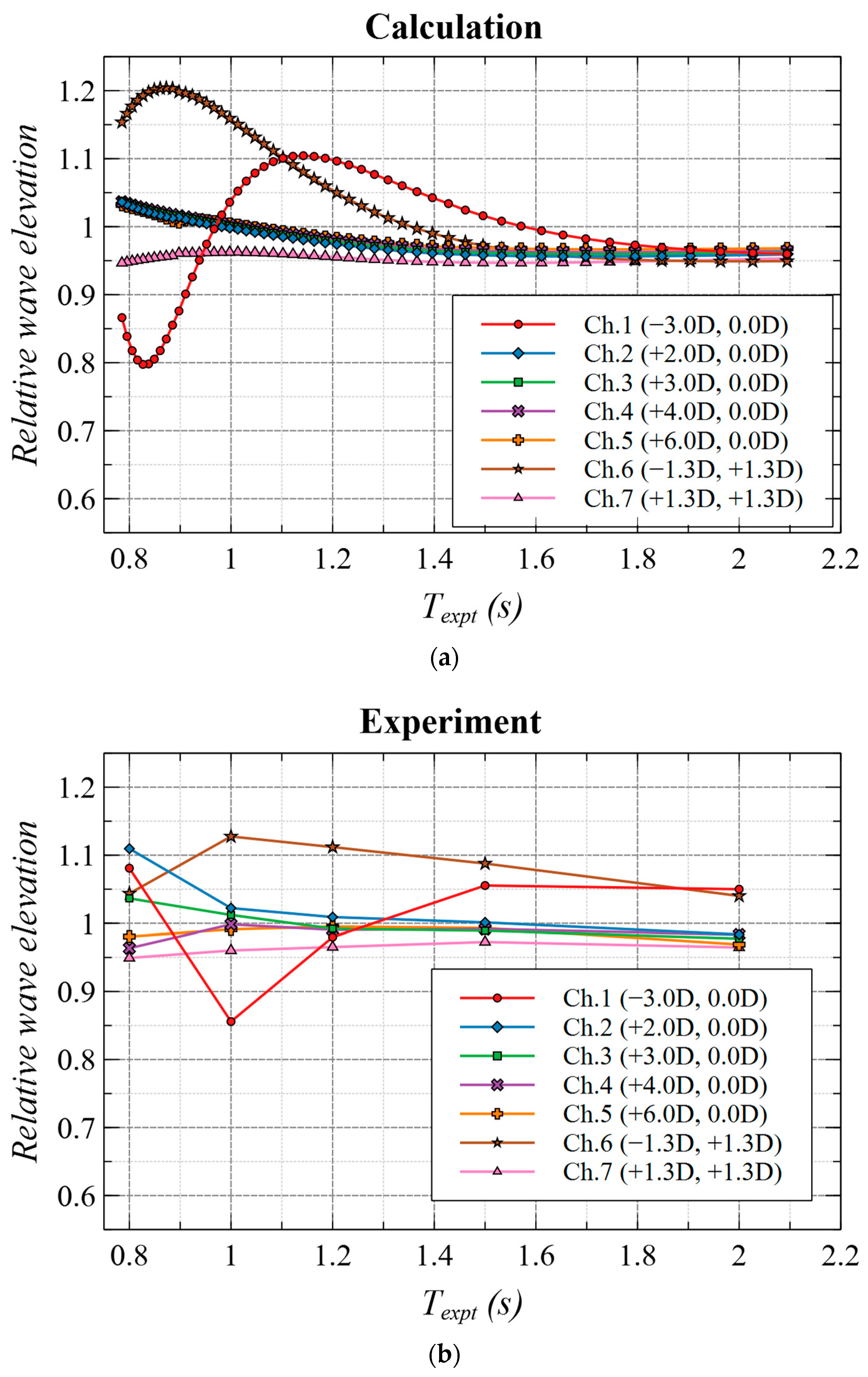
4.2. Validation of Near-Field Wave Elevation with Experiments

After confirming that the motion response of both the foundations was close to zero, the near-field wave elevations were calculated and validated with the experimental results. Figure 8a shows the calculated relative wave elevation, and Figure 8b shows the measured values for the monopile foundation at different channels. Channels 1 and 6 were placed upstream, and Channels 2, 3, 4, 5, and 7 were placed downstream of the monopile foundation. From the plots, it can be confirmed that the trend was similar between the calculations and the measurements.
It can be inferred that the relative wave elevation decreased as the incoming wave period increased for all channels in the calculation. However, the trend was slightly different for the measured values of wave elevation, especially for the upstream channels (Channels 1 and 6) of the monopile foundation. The calculated values slightly overshot the measurement, peaked at different wave periods, and showed a slight increase in the wave elevation upstream of the monopile foundation. The differences between the calculations and experiments could be attributed to the wave tank limitation and the accuracy of the wave measuring sensors. This inconsistency could also be a limitation of the two-dimensional wave tank due to the existence of the side-wall effect. It can be hypothesized that there were some reflected waves due to the side walls of the wave tank and the monopile foundation, which increased the wave elevation measured at the upstream channels. Since these were upstream channels and the objective of the present study is to understand downstream wave elevations, for practical purposes, they can be neglected as the difference was small.
It is worthwhile to notice the near-field wave elevation downstream of the monopile foundation (Channels 2, 3, 4, 5, and 7). Channels 2 to 5 showed that there was a slight increase in the wave elevation for short waves (0.8 to 1.0 s). As the low-energy short-period waves passed through the monopile foundation, they broke and created many small waves around the body, and this led to a slight increase in the wave elevation downstream. But, as the wave period became larger (i.e., waves with longer wavelengths), they had more energy and the wave diffraction phenomenon became much more significant. Therefore, the relative wave elevation slightly decreased due to the interaction of the incoming wave with the monopile foundation. At Channel 7, which was placed closest to the foundation, it was observed that there was a slight decrease in the wave elevation for all wave periods. It can be concluded that the calculated values downstream can be a good representative for predicting wave elevations. The calculation methodology can therefore be validated with the experimental values.
Figure 9 compares the calculated and measured values of the near-field wave elevation for the jacket foundation. The jacket foundation, being a slender structure, had almost no effect on the wave elevation downstream of the foundation, as can be confirmed. It can be said that the diameter of the main structure was extremely small compared with the wavelength of the incoming waves and, therefore, the diffraction was limited. By comparing the results of the monopile and jacket foundations, it can be easily concluded that the jacket foundation had no effect on the wave elevation downstream for the considered range of wave periods.

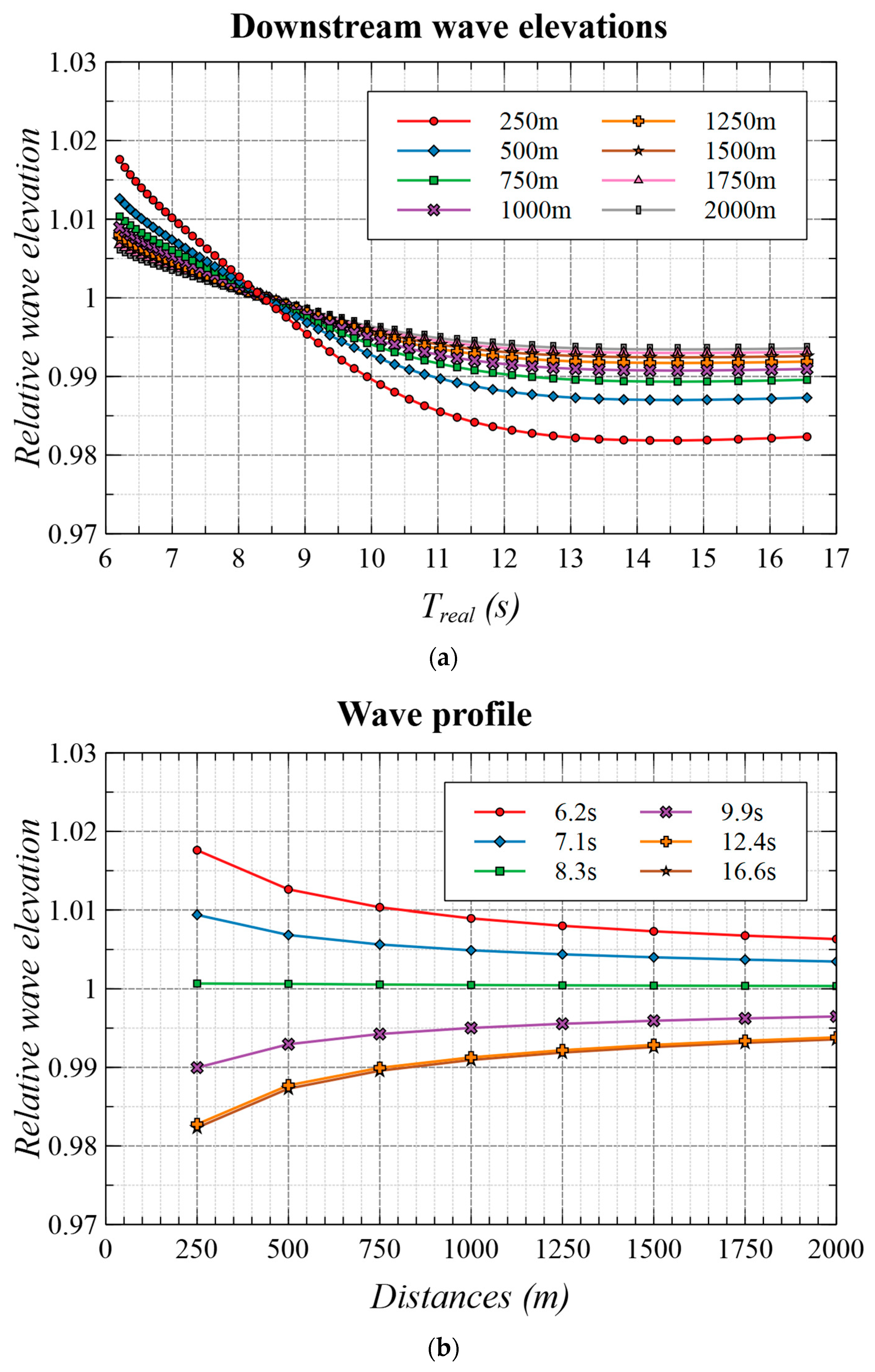
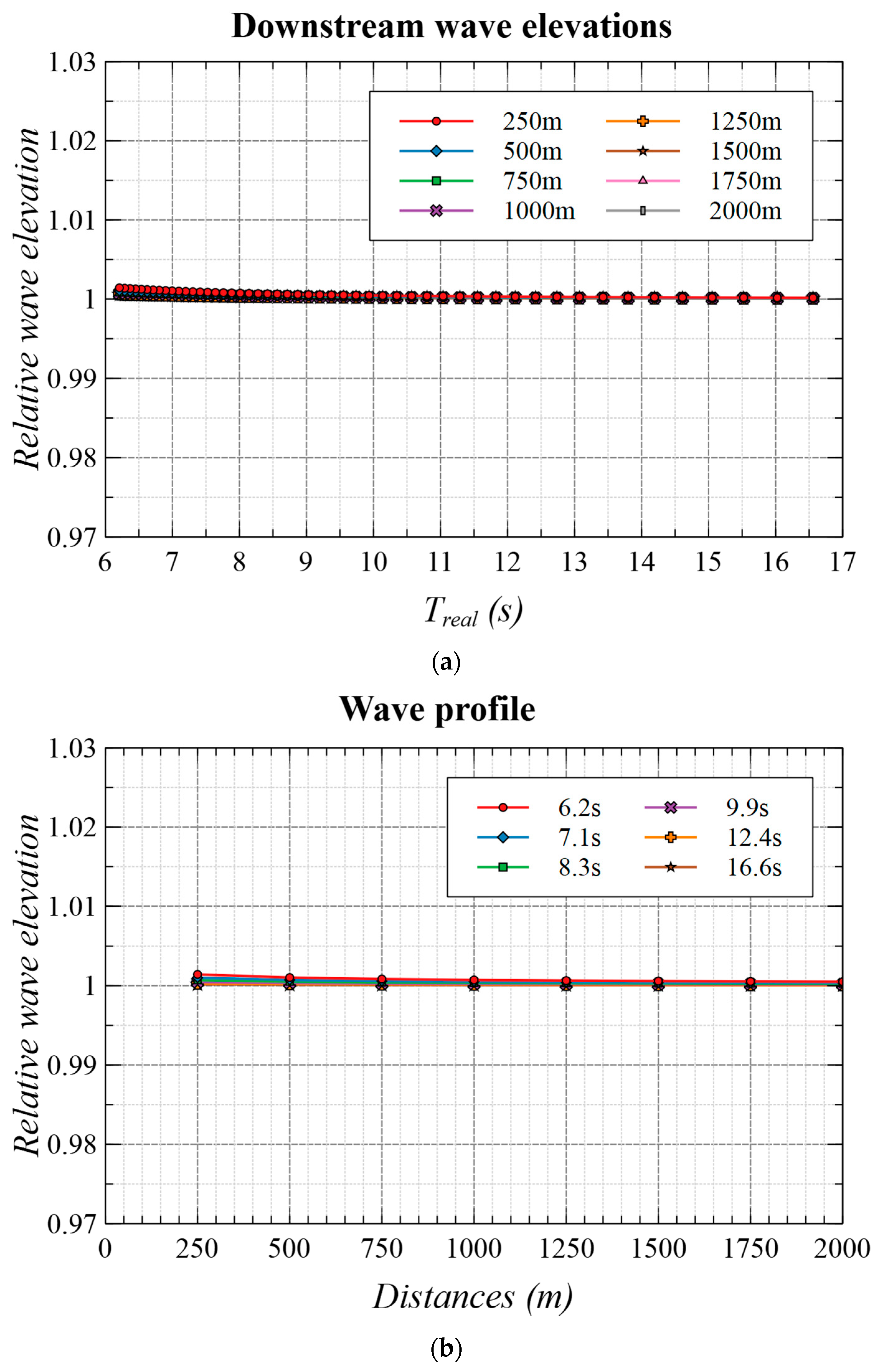
4.3. Far-Field Wave Elevations and Wave Profiles

After validating the calculation method, further calculations were carried out to understand the far-field wave elevation downstream of the fixed-bottom foundations. To understand the wave elevations at a far-away distance, calculations were conducted at 250, 500, 750, 1000, 1250, 1500, 1750, and 2000 m from the foundations at a full scale. Figure 10 and Figure 11 show the obtained results for the monopile and jacket foundations, respectively.
Figure 10a shows the downstream wave elevations, and the corresponding wave profile is plotted in Figure 10b. From Figure 10a, it can be observed that the effect of the monopile foundation on the wave elevations was limited and decreased significantly as the distance from the foundation increased. For a distance of more than 750 m from the monopile foundation, the change in wave elevation was less than 1%. As this distance further increased to 2000 m, the change in wave elevation was less than 0.7%.
Further, the wave period had some influence on the relative wave elevations, and Figure 10b is plotted to understand the wave profiles. There was no reduction in the wave elevation for short waves (6.2 to 8.3 s). For short wave periods, there was a slight increase in the wave elevation downstream due to small waves, as discussed in Section 4.2. However, as the waves became more energetic, there was some reduction in the wave elevation for longer waves (9.9 to 16.6 s), but the reduction became insignificant as the distance from the monopile foundation increased. It is interesting to note that the diameter of the monopile foundation was 10 m at the full scale, and the wavelength for a wave period of 10 s was close to 156 m.
In the case of the jacket foundation (Figure 11a,b), there was no reduction in wave elevation and this was found to be negligible. It is worthwhile to note here that the diameter of the main structure of the jacket is about 1.4 m, and this is the main reason for observing no reduction in the wave elevation downstream. By comparing the monopile and jacket foundations, it can be concluded that the monopile foundation had a limited effect on the wave elevation downstream, and the jacket foundation had no effect.
The calculation methodology can be useful to obtain wave elevations far away from fixed foundations. If the site-specific wave height available for surfing is known, a recommendation for the deployment of an offshore wind turbine can be made. It will help policymakers to decide if the installation of offshore wind turbines can be made further deep in the ocean and co-exist with surfing regions. These findings will be beneficial for offshore wind power companies and policymakers to address the distance of the fixed-bottom foundations from the coast and to achieve social acceptance from surfers and local communities.

5. Conclusions

In this study, the near-field and far-field wave elevations downstream of a fixed-bottom foundation for offshore wind energy applications were evaluated. To this end, two 1.6% scale models, (i) monopile and (ii) jacket foundations that could support a 15 MW offshore wind turbine, were designed and crafted. Near-field wave elevation was measured using wave sensors in a water tank under waves. Further, calculations based on linear potential theory was conducted and the calculation methodology was validated with the experimental results. Far-field wave elevations downstream of the monopile and jacket foundations were then evaluated and the results were compared. The specific conclusions deduced from the study are as follows.
  • The effect of the monopile foundation on the wave elevations downstream was limited, less than 1% at a distance of more than 750 m and less than 0.7% at a distance of more than 2000 m from the monopile.
  • The wave period had some influence on the relative wave elevations, especially for longer waves, but became insignificant as the distance from the monopile foundation increased.
  • The effect of the jacket foundation on the wave elevations downstream was negligible.
The present study showed a limited effect of the monopile and no effect of the jacket foundations on the downstream wave elevation. However, the study did not consider the varying seabed topography in the calculation, and it is desired to conduct such studies in the future for accurate assessment. It is also desired to consider the effect of the array of foundations and currents on wave elevations in the future.

Author Contributions

Conceptualization, S.S. and S.Y.; methodology, S.S. and S.Y.; software, S.S.; validation, S.S.; formal analysis, S.S.; investigation, S.S.; resources, S.Y.; data curation, S.S. and S.Y.; writing—original draft preparation, S.S.; writing—review and editing, S.S.; visualization, S.S.; supervision, S.Y. and S.W.; project administration, S.W.; funding acquisition, S.Y. and S.W. All authors have read and agreed to the published version of the manuscript.

Funding

This research was partly funded by ENEOS Renewable Energy Corporation, Japan. The APC was funded by the Institute of Ocean Energy, Saga University, Japan.

Data Availability Statement

The raw data supporting the conclusions of this article will be made available by the authors on request.

Acknowledgments

The authors are grateful for the support of Masashi Hashiguchi, Koushiro Yoshitake, and Shunpei Konishi in conducting the model-scale experiments.

Conflicts of Interest

Author Shotaro Watanabe was employed by the company ENEOS Renewable Energy Corporation. The remaining authors declare that the research was conducted in the absence of any commercial or financial relationships that could be construed as a potential conflict of interest.

References

  1. Japan 2021–Energy Policy Review, International Energy Agency. Available online: https://iea.blob.core.windows.net/assets/3470b395-cfdd-44a9-9184-0537cf069c3d/Japan2021_EnergyPolicyReview.pdf (accessed on 18 February 2025).
  2. Achieving Net Zero GHG Emissions by 2050 in Japan–Policies and Measures Updated, Ministry of the Environment, Japan. Available online: https://www.mofa.go.jp/files/100153687.pdf (accessed on 18 February 2025).
  3. Shirota, I. Climate Policy in Japan. In The Eighth Tokyo Fiscal Forum; Ministry of Finance: Tokyo, Japan, 2023; Available online: https://www.mof.go.jp/pri/research/seminar/fy2023/tff2023_s2_2_01.pdf (accessed on 18 February 2025).
  4. Clean Energy Strategy to Achieve Carbon Neutrality by 2050. Available online: https://www.japan.go.jp/kizuna/2022/06/clean_energy_strategy.html (accessed on 18 February 2025).
  5. Green Growth Strategy Through Achieving Carbon Neutrality in 2050, Ministry of Economy, Trade, and Industry (METI), Japan. Available online: https://www.meti.go.jp/english/policy/energy_environment/global_warming/ggs2050/index.html#:~:text=In%20October%202020%2C%20Japan%20declared,undertake%20bold%20investment%20for%20innovation (accessed on 18 February 2025).
  6. Offshore Wind Power (Next-Generation Renewable Energy), Ministry of Economy, Trade, and Industry (METI), Japan. Available online: https://www.meti.go.jp/english/policy/energy_environment/global_warming/ggs2050/pdf/01_offshore.pdf (accessed on 18 February 2025).
  7. Hibiki Wind Energy–Kitakyushu Hibikinada Offshore Wind Farm Project. Available online: http://hibikiwindenergy.co.jp/pdf/hwe_english.pdf (accessed on 18 February 2025).
  8. Local Surfers Call for Reconsideration of Offshore Wind Power Generation in Karatsu, Saga. Available online: https://www.surfnews.jp/feature/inside_story/50314/ (accessed on 18 February 2025). (In Japanese).
  9. Why Are (Some) Surfers Against Offshore Wind Farms. Available online: https://www.surfer.com/news/why-are-some-surfers-against-offshore-wind-farms (accessed on 18 February 2025).
  10. Hunter, Illawarra Surfers Paddle Out Against NSW Offshore Wind Zone Plans. Available online: https://www.abc.net.au/news/2023-10-29/offshore-wind-protest-paddle-out-illawarra-hunter/103036846 (accessed on 18 February 2025).
  11. Kimura, A. Characteristics and Generation of Waves Suitable for Surfing. Ph.D. Thesis, Kagoshima University, Kagoshima, Japan, 2016. Available online: https://ir.kagoshima-u.ac.jp/records/3163 (accessed on 18 February 2025). (In Japanese).
  12. Thome, M.; Moctar, O.E.; Schellin, T.E. Assessment of Hydrodynamic Loads on an Offshore Monopile Structure Considering Hydroelasticity Effects. J. Mar. Sci. Eng. 2023, 11, 350. [Google Scholar] [CrossRef]
  13. Wu, C.; Jia, X.; Xu, T.; Zhang, W. Numerical Simulation of the Hydrodynamic Behavior of an Offshore Platform Supported by a Jacket Structure in Waves. Water 2024, 16, 3707. [Google Scholar] [CrossRef]
  14. Kashima, H.; Yoneyama, H. Effect of waves to dynamic response of monopile-type offshore wind power generation facility. J. Jap. Soc. Civ. Eng. 2020, 76, I_887–I_892. (In Japanese) [Google Scholar] [CrossRef]
  15. Bachynski, E.; Thys, M.; Delhaye, V. Dynamic response of a monopile wind turbine in waves: Experimental uncertainty analysis for validation of numerical tools. Appl. Ocean Res. 2019, 89, 96–114. [Google Scholar] [CrossRef]
  16. Ghadimi, B.; Taghikhany, T. Dynamic response assessment of an offshore jacket platform with semi-active fuzzy-based controller: A case study. Ocean Eng. 2021, 238, 109747. [Google Scholar] [CrossRef]
  17. Scroby Sands Offshore Wind Farm–Coastal Processes Monitoring. Final Report. Available online: https://tethys.pnnl.gov/sites/default/files/publications/Scroby_Sands_Coastal_Processes.pdf (accessed on 18 February 2025).
  18. Alari, V.; Raudsepp, U. Simulation of Wave Damping Near Coast due to Offshore Wind Farms. J. Coast. Res. 2012, 28, 143–148. [Google Scholar] [CrossRef]
  19. Bärfuss, K.; Schulz-Stellenfleth, J.; Lampert, A. The Impact of Offshore Wind Farms on Sea State Demonstrated by Airborne LiDAR Measurements. J. Mar. Sci. Eng. 2021, 9, 644. [Google Scholar] [CrossRef]
  20. McCombs, M.P.; Mulligan, R.P.; Boegman, L. Offshore wind farm impacts on surface waves and circulation in Eastern Lake Ontario. Coast. Eng. 2014, 93, 32–39. [Google Scholar] [CrossRef]
  21. Christensen, E.D.; Kristensen, S.; Deigaard, R. Impact of an offshore wind farm on wave conditions and shoreline development. Coast. Eng. Proc. 2014, 1, 87. [Google Scholar] [CrossRef]
  22. Wu, W.; Di, T.; Yang, X.; El Naggar, M.H.; Zhang, Y. Revised pile-pile mutual interaction factors for seismic analysis of end-bearing pile groups embedded in saturated stratum. Soil Dyn. Earthq. Eng. 2024, 182, 108745. [Google Scholar] [CrossRef]
  23. Zhang, Y.; Zhang, F.; El Naggar, M.H.; Wu, W. Seismic response of pile group embedded in unsaturated soil considering the coupling of kinematic and inertia pile-pile interactions. Comput Geotech. 2025, 178, 106937. [Google Scholar] [CrossRef]
  24. Zhu, S. Diffraction of short-crested waves around a circular cylinder. Ocean Eng. 1993, 20, 389–407. [Google Scholar] [CrossRef]
  25. Cong, P.; Gou, Y.; Teng, B.; Zhang, K.; Huang, Y. Model experiments on wave elevation around a four-cylinder structure. Ocean Eng. 2015, 96, 40–55. [Google Scholar] [CrossRef]
  26. Stratigaki, V.; Troch, P.; Forehand, D. A fundamental coupling methodology for modeling near-field and far-field wave effects of floating structures and wave energy devices. Renew. Energy 2019, 143, 1608–1627. [Google Scholar] [CrossRef]
  27. Srinivasamurthy, S.; Iwamatsu, S.; Hashimoto, K.; Suzuki, H.; Chujo, T.; Haneda, K.; Nihei, Y. Study of slow-drifting damping on wind tracking performance of a new-type FOWT ‘Optiflow’ with single-point mooring. Ocean Eng. 2021, 242, 110131. [Google Scholar] [CrossRef]
  28. Srinivasamurthy, S.; Ishida, S.; Yoshida, S. Investigation into the Potential Use of Damping Plates in a Spar-Type Floating Offshore Wind Turbine. J. Mar. Sci. Eng. 2024, 12, 1071. [Google Scholar] [CrossRef]
  29. Gaertner, E.; Rinker, J.; Sethuraman, L.; Zahle, F.; Anderson, B.; Barter, G.; Abbas, N.; Meng, F.; Bortolotti, P.; Skrzypinski, W.; et al. Definition of the IEA Wind 15-Megawatt Offshore Reference Wind Turbine; Technical Report; No. NREL/TP-5000-75698; National Renewable Energy Lab. (NREL): Golden, CO, USA, 2020. Available online: https://www.nrel.gov/docs/fy20osti/75698.pdf (accessed on 18 February 2025).
  30. HydroStar Software. Available online: https://marine-offshore.bureauveritas.com/hydrostar-software-powerful-hydrodynamic (accessed on 18 February 2025).
  31. Rhino CAD Software. Available online: https://www.rhino3d.com/ (accessed on 18 February 2025).
Figure 1. Surfers’ preferred and minimum surfable wave height (the data are from [11]).
Jmse 13 00661 g001
Figure 2. Monopile foundation.
Jmse 13 00661 g002
Figure 3. Jacket foundation.
Jmse 13 00661 g003
Figure 4. Measurement sensor channel locations in waves. (a) Monopile; (b) jacket.
Jmse 13 00661 g004
Figure 5. An example of the calculation procedure in HydroStar.
Jmse 13 00661 g005
Figure 6. Monopile foundation response to waves. (a) Surge; (b) heave; (c) pitch.
Jmse 13 00661 g006aJmse 13 00661 g006b
Figure 7. Jacket foundation response to waves. (a) Surge; (b) heave; (c) pitch.
Jmse 13 00661 g007aJmse 13 00661 g007b
Figure 8. Wave elevations around monopile foundation. (a) Calculation; (b) experiment.
Jmse 13 00661 g008
Figure 9. Wave elevations around jacket foundation. (a) Calculation; (b) experiment.
Jmse 13 00661 g009
Figure 10. Monopile foundation. (a) Downstream wave elevation; (b) wave profile.
Jmse 13 00661 g010
Figure 11. Jacket foundation. (a) Downstream wave elevation; (b) wave profile.
Jmse 13 00661 g011
Table 1. Principal particulars of monopile foundation.
Model SpecificationsFull-Scale Model1.6% Model
Diameter of monopile (m)10.00.16
Thickness of monopile (m)0.30.005
Water depth (m)20–601.0
Rated power (MW)15-
Rotor diameter (m)236-
Hub height (m)150.0-
Tower base height (m)25.0-
Tower base ultimate moment (MNm)600-
Table 2. Principal particulars of jacket foundation.
Model SpecificationsFull-Scale Model1.6% Model
Diameter of main structure (m)1.40.023
Diameter of brace (m)0.40.007
Water depth (m)20–601.0
Base width (m)26.00.416
Deck width (m)20.00.32
Rated power (MW)15-
Rotor diameter (m)236-
Hub height (m)150.0-
Tower base height (m)25.0-
Tower base ultimate moment (MNm)600-
Table 3. Experimental conditions.
Experimental ConditionsFull-Scale Model1.6% Model
Wave height (m)1.25–3.750.02, 0.04, 0.06
Wave period (s)6.3–16.60.8, 1.0, 1.2, 1.5, 2.0
Disclaimer/Publisher’s Note: The statements, opinions and data contained in all publications are solely those of the individual author(s) and contributor(s) and not of MDPI and/or the editor(s). MDPI and/or the editor(s) disclaim responsibility for any injury to people or property resulting from any ideas, methods, instructions or products referred to in the content.

