Abstract
In some ports, there are separate very narrow places between the quays and other navigational obstacles, where the distance between the quays or between the quays and navigational obstacles is very small. Narrow gaps or channels in the water area, where quays are built and ships are berthing, make it difficult for ships to berth at such quays. Accurate knowledge of a ship’s manoeuvrability characteristics, combined with the application of these characteristics in berthing operations and the optimal use of tugboat capabilities, allows for better utilization of restricted port spaces. The article presents a developed ship berthing methodology designed for ship berthing in extremely limited conditions, utilizing the ship’s manoeuvrability capabilities and maximizing the capabilities of tugboats when mooring ships in extremely limited conditions. The developed methodology was tested with real ships and tugboats in specific port conditions and using calibrated simulators, and the results of the experimental research and theoretical calculations are presented in the article as a case study. The research results (methodology) obtained and presented in the article can be applied to any ships and ports, precisely adapting them to specific port situations. The article studies ship manoeuvrability and tugboat capabilities under various hydrometeorological and hydrological conditions, assesses the impact of shallow depths (shallowness), and determines the boundary conditions for ship berthing.
Keywords:
navigation; manoeuvring; tugboat; towage; berthing; navigational safety; port tug evaluation 1. Introduction
In some ports, there are very narrow water areas between the quays or between the quays and other navigational obstacles. In such places, the berthing of ships is complicated; therefore, it is very important to accurately assess the manoeuvrability of ships and environmental conditions in order to optimally use similar port locations [1]. In very limited port water areas, it is not possible to use traditional tugboat service schemes; therefore, new tugboat service schemes and non-traditional ship berthing systems need to be sought. When developing ports, it is not always possible to prepare suitable (wide) basins for various reasons, for example historical objects that cannot be removed, already built and operating ports, or other industrial objects. However, there are still remaining territories and water spaces in the port territory that should be effectively used [2].
At the same time, ship parameters are constantly increasing, and ports are trying to accommodate the largest ships possible at specific terminals, which do not always have the opportunity to develop infrastructure, especially port basins and canals. Recently, i.e., over the past decades, many ports have managed to increase the parameters of ships accepted into the port by two or more times, expanding port entrance channels and ship turning basins, but inside the ports, for various reasons, often due to cities located near the port and other constructions, there is no possibility to expand port basins accordingly [3].
Individual ports change their purpose, with changes in cargo flows, terminal technologies, ship types, and their purposes. In many cases, as ship parameters increase while infrastructure parameters do not drastically increase, problems arise when berthing ships, and it is necessary to look for new ship berthing methods using tugboats or ship steering equipment (thrusters) [4,5].
As ship parameters increase, more tugboat assistance is needed to improve ship manoeuvrability during mooring and unmooring operations in ports. Over the past decades, new large ships have been built, such as PANAMAX, POST PANAMAX, SUEZMAX bulk carriers and tankers, E and G class container ships, and other extremely large ships. However, at the same time, port channels and water areas have not advanced as fast as ship parameters, so more tugboat assistance is needed, and new towing methods and new types of tugboats with wider manoeuvrability are being developed. For example, tugboats using azimuth propulsion systems (Azipod Systems, as the azimuth stern drive (ASD) is called), which are equipped with most modern port tugboats [1], and new more accurate navigation systems in ports, such as real-time kinematics (RTK), lasers, etc. At the same time, new powerful tugboats are being built and it is very important to study the advantages and disadvantages of tugboat working methods as accurately as possible in order to use tugboats more efficiently and increase their capabilities in performing mooring operations in extremely limited port areas [6].
At the same time, it is necessary to understand that tugboats can only operate in very limited port water areas using the push/pull method, and in some cases only using the side towing principle. Very often tugboats cannot always use maximum power due to the very short manoeuvring time, with a small distance between the ship and the tugboat, especially when pulling the ship from the quay or holding it so that the ship does not approach the quay at too high a speed [7].
Theoretical studies of new tugboat working methods in ports, along with experimental tests on real ships with the help of calibrated simulators, were the main research direction. The aim was to develop a methodology for calculating the tugboat towing power in real conditions when the tugboat propellers are close to the ship’s hull, which is an important problem for assessing the change in the tugboat’s pulling force. The article analyses the situation of tugboat working methods in ports, discusses the theoretical basis for calculating the tugboat’s pulling force, analyses experimental and test results, and presents conclusions.
At the same time, towing methods have both advantages and disadvantages, especially when towing large draft ships and using tugboats with limited pushing/pulling force capabilities. Theoretical and practical studies of the advantages and disadvantages of new types of tugboat working methods in ports, especially assistance when pushing/pulling the tugging ships, are very important in order to correctly and optimally use the new types of tugboats providing assistance to ships manoeuvring and berthing in extremely limited water area conditions.
Studies of the use of tugboats, assessing the counterforce created by the flow of tugboat propellers, have allowed for a more accurate assessment of the tugboats’ capabilities in ship berthing operations.
This article examines the possibilities of ship berthing in extremely limited conditions, applying the developed methodology, which allows for assessment of the possible and necessary additional forces created by tugboats, using “side towing” and exploiting the capabilities of the ship’s propulsion and berthing (thrusters) systems.
The novelty and innovation of the article are based on the development of a new methodology for ship berthing in extremely limited conditions, with small distances between berths or between berths and other navigational obstacles and the assessment of tugboat capabilities due to very small distances between the tugboat propellers and the hull of the berthing ship.
The methodology developed and presented in this article for mooring ships under extremely limited conditions using side towing of ships during mooring operations is new and highlights the effect of tugboat thrust (reverse forces) at short distances between the tugboat propellers and the hull of the moored ship. These are very important factors during ship mooring processes in very limited port areas.
2. Analysis and Literature Review of Particularly Restricted Port Locations
Many ports in the world have extremely limited areas, which they try to use optimally, i.e., to accommodate ships in such areas. While old ports, especially those located within city limits, do not have much opportunity to expand, larger ships are appearing on the market and the need to transport passengers and cargo through such ports is high [8]. Historically, ports were developed in or near cities, and the cities themselves developed quickly and “overtook” port territories from several sides [9]. For example, the southern part of Klaipeda port was far from the city a few decades ago, but later the city expanded far and the southern part of the port remained surrounded by the city [9]. A similar situation, when the city partially “displaced” the port, has developed in many countries in Europe and other regions, for example, Rotterdam (Netherlands) [10], Antwerp (Belgium) [11], Bremen (Germany) [12], and similar ports.
Some ports have stopped developing in urban areas and started to develop intensively outside the city limits or have “won” a place for port development at sea, for example Rotterdam (Netherlands) in newly formed areas at sea [13]. Zeebrugge (Belgium) [14] and other ports have developed similarly. At the same time, some ports carry out their development within the existing port area, and as a result, places appear in the ports where there are very limited water areas where large ships must moor [15]. The literature provides a number of examples related to port development and the difficult conditions for ship berthing in developing port areas due to canal and water area restrictions [15,16]. Such locations include the entrances to locks, where ships need to be “pushed” to the quay before entering the first lock chamber, for example when entering the new Panama Canal locks [17,18], or where ships enter the locks directly without the assistance of tugs, for example in the Kiel or Brunel Canal locks [19,20].
Old ports located within city limits and not having the opportunity to develop ports outside the city limits are also trying to keep up with progress and maximize their capabilities to accommodate larger ships, so the manoeuvrability of ships and the maximum use of tugboat capabilities are very important for them. Such ports include Venice (Italy) [21], Helsinki (old) (Finland) [22], and other ports.
At the same time, when analysing ship berthing in extremely confined conditions (in locks, confined port areas, etc.), little attention was paid to aspects of ship controllability during ship berthing operations, which are very important in extremely confined conditions (Figure 1 and Figure 2).
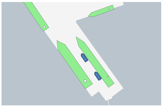
Figure 1.
Ship berthing operation with the help of two tugboats using the side-towing method [23].
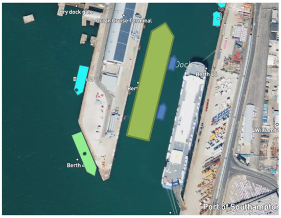
Figure 2.
Berthing of a ship at Southampton Ocean dock with another ship moored at the opposite quay of the dock [23].
Ports use traditional and new tugs with “Azipod” systems to increase the manoeuvrability of ships entering the port and make it safer for ships performing berthing and unmooring operations. Old (conventional) tugs mainly use short tug lines to increase the manoeuvrability of the ship. This towing system is not flexible enough, as it requires more water areas in ship turning basins, at quays, wider channels, etc.
New tugs equipped with ASD systems (of the ‘tractor’ type) have greater manoeuvrability and can move in any direction with an approximately equal pulling or pushing force. This means that turning the ship or approaching or departing from the quay in limited port waters is a great advantage for manoeuvring large ships. To help manoeuvre the ship, tugs usually use a short rope system that requires less space (water area).
In very narrow places, there is no room for traditional tugboat work (using tugboats or a typical push/pull system). At the same time, it is necessary to take into account that when the tugboat is towing a ship, the flow of the tugboat’s propeller moves on the hull of the moored ship and creates a force opposing the pulling force of the ship [2,5,7].
Tugs with ASD systems or impeller drives often use a push/pull method to help manoeuvre the ship, especially when water areas are limited. This means that there may be less space in canals, ship turning basins, or approaches to quays for successful ship-turning or berthing operations, which is an advantage for large ships in particularly limited conditions [24,25,26,27].
Theoretical and practical studies of the advantages and disadvantages of the new type of tugboat working methods in ports, especially when using the push/pull method, are very important for the correct and optimal use of new types of tugboats providing tugboat services in ports on ships. This is especially important when it is necessary to support a ship approaching the quay or when pulling a ship away from the quay, when wind and current directions are towards the quay in very limited port water areas.
The main goal of this article is to investigate and create ship berthing systems and methods that would allow for the safe mooring of ships in extremely limited conditions, utilizing the ship’s manoeuvrability and port tugboat capabilities, and to find optimal solutions for the safe berthing of ships in extremely limited conditions using modern port tugboats.
3. Theoretical Justification for Mooring Ships in Extremely Confined Conditions
Berthing of ships in extremely limited conditions is theoretically related to the controllability of the ship, including the use of tugboats, i.e., the forces and moments created by tugboats. Therefore, it is very important to assess the forces and moments acting on the ship as accurately as possible and to determine the exact location of the ship during the manoeuvre, as well as the movement parameters of the ship and tugs.
3.1. Steps of Research Methodology
The following steps of the research methodology were used to conduct the study: analysis of ship berthing in ports under very limited space conditions; literature review and data collection; development of a mathematical model; performance of calculations using the developed mathematical model; performance of experiments on real ship berthing under very limited space conditions; use of a calibrated simulator to perform ship mooring under very limited space conditions; calibration of the mathematical model based on the results of the experiments; and discussion and drawing conclusions (Figure 3).
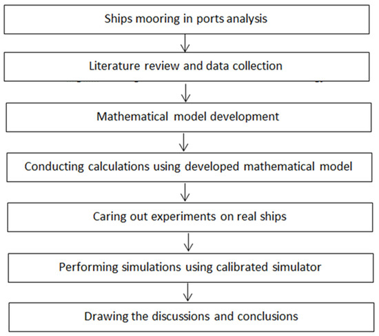
Figure 3.
The algorithm of the research methodology.
Based on the presented basic methodology (Figure 3), a theoretical model of forces and moments acting on a ship during berthing of ships in extremely limited conditions (in the water area) was developed. In order to improve the developed model and verify it, experiments were performed with real ships and tugboats. The parameters of the ships and port tugs used in the experiments, as well as the simulator used, and the simulator calibration method, are presented in Section 4. Based on the experimental results obtained with real ships, the simulator was calibrated and experiments were performed using the calibrated simulator. Finally, based on the experimental results obtained, the theoretical model of forces and moments acting on berthing ships was improved. We determined the possible optimal conditions for ship berthing operations and the possible maximum accuracy of the results obtained during ship berthing in extremely limited conditions using high-precision navigation systems during berthing operations under various hydrological and hydrometeorological conditions. The experimental results were processed using the Kalman filter [28] and the maximal distribution method [29].
Accurate determination of the ship’s position and movement parameters during ship berthing operations under extremely limited conditions, using extremely high-precision navigation systems [30,31,32] and applying the developed calculation model of the forces and moments created by the ship and tugboats, makes it possible to accurately determine the necessary tug impact under extremely limited conditions at the ship’s berthing location.
Currently, simulators are often used, with the help of which various situations can be created. At the same time, it is difficult to enter all possible parameters in simulators, especially for dynamic objects (ships), such as real ship draft, displacement, and the like. Therefore, it is very important that the ship parameters in the simulator are as close as possible to the real ships. Based on the results of experiments on real ships, the calibration coefficients can be calculated as accurately as possible. Using the calibration coefficients, the necessary ship berthing parameters can be obtained with the help of simulators under extremely limited conditions [33,34]. To confirm the theoretical results, it is very important to conduct experiments on real objects (ships) berthing in extremely limited conditions using highly accurate navigation equipment [30,31,32], and according to the results obtained, adjust the mathematical models so that they can be applied to any dynamic objects (ships) and in various port locations.
Then, the results were analysed, discussions were initiated, conclusions were drawn, and further research was proposed.
3.2. Mathematical Model
Berthing of ships in extremely confined conditions requires an accurate assessment of the forces and moments acting on the moored ships. External forces and moments acting on the ship during the berthing operation in extremely confined port conditions must be compensated by the forces and moments created by the ship’s rudder, thrusters (if any), and the forces and moments created by tugs (if tugs are used). The motion of the ship is usually described mathematically by D’Alembert’s principles. Thus, the calculation of forces and moments can be performed using a mathematical model based on D’Alembert’s principle [5,35]:
where —the inertial forces and moment; —the forces and moment created by the ship’s hull, which could be calculated using the methodology given in [5,36]; —the ship’s hull as a wing-related force and moment, which could be calculated using the methodology given in [36]; —the forces and moment created by the ship’s rudder or other steering equipment [5]; —the forces and moments created by the engines [5]; —the aerodynamic forces and moment, which could be calculated using the methodology given in [37]; —the forces and moment created by the current, which could be calculated using the methodology given in [38]; —forces and moments generated by waves, which could be calculated using the methodology presented in [36,38] (in port conditions this parameter is insignificant and often not applied); —forces and moments generated by the shallow water effect [5,35,36,37] (in port conditions this parameter is very important, especially when the draft-to-depth ratio of the ship during mooring operations is greater than 0.9); —forces and moments generated by the ship’s propeller(s), which could be calculated using the methodology presented in [5,36]; and —forces and moments generated by the tugs. Additional forces and moments may be generated by anchor or mooring lines or other factors.
Equations (1)–(3) are universal and can be applied to various conditions of ship navigation at sea and in port.
Taking into account the very limited places in the ports, ships are turned around (if necessary, in advance in the ship turning basin or in another place in the port water area).
Large ships during berthing in ports, in particularly limited conditions, usually use the help of port tugs, especially if the ship does not have its own additional propulsion devices (thrusters). In particularly limited places in ports, there are no waves in most cases, the current changes little when the ship moves to the quays or it is insignificant. When the ship moves to the quay, only transverse forces (in the Y direction) act, therefore, only forces in the Y direction can be analysed further.
Thus, Equation (2) can be written as follows:
In the case where the ship does not have a steering device and the ship’s propulsion device is ineffective for lateral movement of the ship (traditional rudder–propeller complex), and all ship control is performed by a tugboat or tugboats, Formula (4) can be written as follows:
The inertia forces, under the typical conditions of moving to quay in very limited port water areas, could be expressed as follows [39]:
where —ship’s mass; —ship’s acceleration on direction.
The aerodynamic force () can be calculated as follows:
Here, —aerodynamic coefficient, in calculations it is possible to accept about 1.07–1.3 [36,38]; —air density, in calculations it is possible to accept about 1.25 kg/m3; —area of projection of the ship’s freeboard onto the diametrical plane; —wind speed; —angle of wind heading to the quay.
The effect of shallowness on the ship’s movement during the mooring operation can be calculated as follows:
Here: —hydrodynamic coefficient, for the ships could be taken as 1.5 [36,38]; ship’s length between perpendiculars; average ship’s draft; ship’s movement speed at the quay, can be accepted as the possible maximum contact speed with the quay’s fenders [40]; and depth at the quay.
The main object controlling the ship in this case, when the ship moves to or from the quay in extremely limited conditions, is the tug or tugs. In the case where the tugs can work in the traditional push/pull method (Figure 1, Figure 2 and Figure 4), the pushing force created by the tugs can be calculated as follows [36,38]:
where —the propeller coefficient for practical calculators can be accepted as 0.20 ÷ 0.22 [36,38]; —water density; —propeller revolutions; —the diameter of the propeller; —the coefficient of propeller propulsion for practical calculations can be agreed as 0.15 ÷ 0.20 [36,38] (the specified propeller coefficient corresponds to traditional propellers used in ASD and Z tugboats); and —tug resistance when speed is very low (ship mooring or unmooring conditions), and is close to 0.
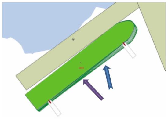
Figure 4.
Traditional tugboat push/pull method used in ship berthing operations (blue arrow—current; purple arrow—wind) [34].
The traditional tugboat pulling/pushing method could be applied to many ship manoeuvring operations in port areas (Figure 4), as this method requires less water area. In particularly confined conditions, positioning the tugboat perpendicular to the ship is often not enough space and, in such cases, positioning the tugboat alongside the ship is possible (Figure 1 and Figure 2). In the push/pull method, the tug and the ship are coupled close together. In the case where the tug pushes the ship, the pushing force is equal to the calculated Formula (9). When towing a ship, two very important elements must be taken into account, i.e., the vertical angle of the tow line and the effect of the water flow created by the tug’s propeller on the ship’s side when pulling the ship away from the quay or holding it when approaching the quay.
The vertical angle of the tug line reduces the horizontal pulling force of the tugboat, as shown in Figure 5, and can be calculated as follows:
where —the vertical angle of the tug line.
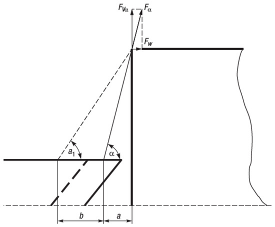
Figure 5.
Vertical angle α and changes of the tug rope.
It is also necessary to consider an increase in the length of the tug line.
An increase in the length of the tug line when using synthetic ropes could reach up to 20% (since currently many tugboats use high modulus polyethylene (HMPE) [1] towing ropes on the tugboat winch). Their length increase is only about 2–3 percent, but when using the pull/push towing method, tugboats often increase the distance between the ship and the tugboat, “spending” a larger length of the towing rope to increase the actual towing force (if the environment “allows”). Some tugboats still use traditional synthetic ropes; in such cases, changes in the vertical angle could be calculated as follows:
where —height between the tugboat winch and the towing rope attachment point on the towed vessel; —initial rope length; and —towing rope elongation coefficient, which depends on the rope characteristics.
In some ports, during pulling operation when using the method of tugboat pulling/pushing the distance between the ship and tugboat increases up to 10 ÷ 15 m (using tugboat winch). In such cases, angle can be calculated as follows:
The distance between the tugboat’s propeller(s) and the side of the towed vessel is important because the flow(s) of the tugboat’s propeller(s) creates a force opposing the direction of towing of the vessel. Although in most cases it is not taken into account in practice, this counterforce created by the tugboat’s propeller(s) can have a significant impact on the total pulling force of the tugboat(s). The current velocity caused by the rotating propeller, the so-called induced current velocity, can be calculated as follows [41,42,43]:
where —the thrust coefficient of the screw that could be taken for the study case is 0.30 ÷ 0.40 [41].
The induced jet speed for tug propellers can be calculated as follows:
where —the coefficient of the induced jet speed depends on the diameter of the tug propeller and the distance (S) between the propeller and checking point (ship hull) and was received by conducting theoretical investigations and experimental tests on real tugs (Figure 6) [44].
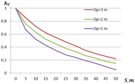
Figure 6.
The coefficient of the induced jet speed depends on the diameter of the tugboat propeller and the distance between the propeller and checking point (ship hull).
The induced jet speed produced by screw propellers used in tugboats directly influences the ship hull (creating resistance depending on the hull shape of the pulled ship) square affected by the induced jet, which is equal to the square of the crew propeller and can be calculated as follows:
The additional force created by the screw propeller can be calculated as follows [37,39]:
where —the hydrodynamic coefficient taken from 0.5 to 2.0 (2.0 is used in cases where the screw propeller acts in a perpendicular manner to the ship hull as to the vertical wall, which conforms to the pulled ship having high draft); and —the number of tug propellers.
The compiled effect of the propeller flow on the hull of the moored ship, depending on the propeller diameter and revolutions, clearly demonstrates that when tugboats are moored (fixed) close to the ship’s hull and are pulling the ship, the optimal number of propeller revolutions or the angle of rotation of the propeller blades is critical during such operations. Thus, the preliminary accurate determination of the propeller operating parameters directly affects the created traction force of the tugboats and the safe mooring operation of the ship.
Finally, the total force of tug pulling employing the pull/push method when the tug is located close to the ship, not taking into account shallowness and aerodynamic force created by wind, can be expressed as follows:
The last formula shows that if the vertical angle of the tug rope is very large (close to 80 degrees), the tugboat’s pulling force may be very small or in some cases may have a negative effect, which means that the force created by the propeller screw on the hull of the towed vessel may be greater than the useful pulling force created by the tugboat(s).
The total pulling force created by the tugboats acting on the towed vessel when the wind is blowing onshore and the depth at the berthing of the vessel is shallow, which affects the parameters of the vessel’s movement, can be written as follows:
It is very important to calculate in advance the possible reserves of the tugboat’s traction force under various hydrometeorological and hydrological conditions, depths, and operating conditions of the tugboats (the angle of the tow rope between the tugboat and the towed vessel’s tow rope attachment point and the speed of rotation of the tugboat(s) propeller) in order to assess the available real traction force of the tugboats. The effective reserve force could be calculated as follows:
In this way, the developed methodology for berthing ships in extremely limited port water area conditions, which includes the parameters of the towed ship and tug(s), hydrometeorological and hydrological conditions, and the depth of the water area at the ship’s berthing location, can be used in similar situations.
4. Case Study on Mooring Ships in Port Extremely Confined Conditions Using Tugboats
In order to verify the validity of the theoretical model and its practical application, experiments were conducted with real ships and tugboats. Using the developed methodology (presented in Section 3 of the article), it was verified and validated by conducting experiments with real ships and tugboats during ship mooring operations. The results of the experiments with real ships and tugboats were also used to calibrate the simulator SimFlex Navigator [34]. The calibrated simulator was further used to study various ship mooring situations under extremely limited conditions.
The calculation results obtained using the methodology presented in Section 3 and the experimental results obtained with real ships and using the simulator for the same ship berthing under extremely limited conditions were processed by the Kalman filter [28] and maximum distribution [29] methods. The obtained results were compared with each other (for analogous manoeuvres) and conclusions were drawn about the possibilities and limitations of the use of the developed model.
The port quays where POST PANAMAX or larger ships are moored were selected for the case study (Figure 1, Figure 4). These port locations were chosen not only to investigate the berthing capabilities of ships under extremely limited conditions but also to conduct experiments with real ships. The port locations selected for the study are exposed to wind, to currents in some places, and have limited depths. The studies were conducted using the principles of side towing and push/pull, as shown in Figure 1 and Figure 4. The experimental program was prepared in advance, and all participants were introduced to it, including ship and tugboat captains, pilots, and the port vessel traffic control service (VTS). The experimental conditions were described, such as the maximum possible lateral speed of the ships, and the maximum possible power used by the tugboats (leaving a reserve of tugboat power). The current hydrometeorological and hydrological conditions were assessed (wind speed and direction, current direction and speed, depth under the ship’s keel, and possible manoeuvres of the ship’s propulsion system).
During the experiments with real POST PANAMAX bulk carriers and port tugboats, the equipment available on the tugboats was used, which measures and records the tension of the towing rope every second with an accuracy of ±1 kN. To fix the position of the ship, a differential global positioning system (DGPS) was used [30], with the help of which the ship’s location was determined with an accuracy of ±0.3 m, and a real-time kinematic system (RTK) [31], with the help of which the ship’s location was determined with an accuracy of ±0.05 m, the ship’s speed with an accuracy of ±0.02 m/s, and the ship’s angular rotation rate with an accuracy of about ±0.02 rad/s.
During the ship’s berthing manoeuvres, high-precision navigation systems (DGPS and RTK) were used to obtain bands of ship motion parameters (ship position, lateral ship motion, and ship angular rotation rates) using a 95% probability. After calculating the average values of the above parameters and the “scatter” values of the parameters, they were compared with the permissible values of the absorption energy of the quays’ fenders in order to guarantee the safety of the quays and the safe removal of ships in very restricted ship berthing areas.
Using a visual ship’s bridge simulator [34], similar accuracy of the previously specified parameters was obtained. For measurements of external parameters (wind, currents) stationary measuring stations operating in the port (hydrometeorological and current measurement) were used [9].
The results of the experiments with real ships were used to calibrate the simulator. The simulator was calibrated as follows: ships and tugboats of the same type with the closest possible geometric parameters (ship length, width, draft, total hull fullness coefficient, etc.) were taken from the simulator library, and similar external conditions were introduced (wind speed and direction, current direction and speed, depths, the same geographical location, etc.). After performing similar actions in the simulator as with real ships, the simulator test results were obtained. When the simulator was further used to perform other similar experiments, the results obtained with the help of the simulator were corrected with calibration coefficients so that they were as close as possible to the analogous manoeuvre parameters of real ships.
For practical evaluation of the research, based on the methodology presented in Chapter 3, calculations were performed and the magnitudes of the traction force of the tugboats were checked, as well as the possible effect of the propeller flow, depending on the propeller diameter and distances between tugboat propellers and ships hulls. During unmooring operations, tugs used the push/pull and side towing methods and short ropes.
Calculations and experiments were performed to determine the effect of the tugboat propeller flow on the “wall”, i.e. the hull of the ship (POST PANAMAX type bulker with a draft of about 11 m), which is close to the tugboat propellers. The experiments were performed by pulling the ships away from the quay, by mooring them, or by keeping the ships at a minimum speed of approaching the quay, when the wind and/or current direction is towards the quay.
Using the methodology presented in Chapter 3, the additional forces created by tugboats using side and pull/push towing methods on the towed vessel, as well as the tugboats’ traction forces created by the tugboats, depending on the angles of the towing ropes between the vessel and the tugboats’ attachment points, were investigated (Figure 5).
For experimental studies, partially loaded POST PANAMAX bulk carriers with a length between perpendiculars of about 215 m, a width of about 32.5 m, a draft of about 11 m, a deadweight of about 55,000 t, and a projected area of the freeboard to the diametrical plane of about 2500 m2 were accepted. Such fully loaded POST PANAMAX bulk carriers were used in the study since their fully loaded draft is 13.3 m and their deadweight is about 80,000 t. Typical port tugs with DSP systems with a length of about 30 m, a width of about 10 m, a draft of about 4.5 m, a propeller diameter of about 2 m, a main engine power of about 3370 kW, and a maximum tractive force of about 500 kN were accepted for the research (Figure 7).
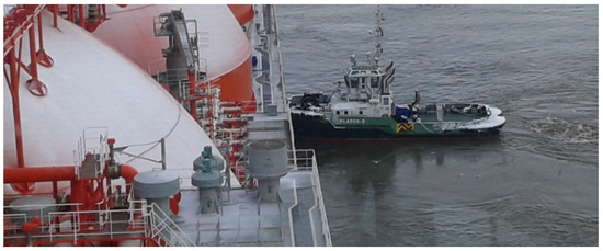
Figure 7.
Typical port tugboat using ASD (tractive force of about 500 kN) used for research, operating in a push/pull.
Depending on the towing rope angle, up to 90% load on the main engines of the tugboats, using the methodology developed in Chapter 3, is presented in Figure 8. Figure 8 presents the pulling force of two tugboats using the side towing method, depending on the angle of the towing lines between the tugboats and the towed vessel.
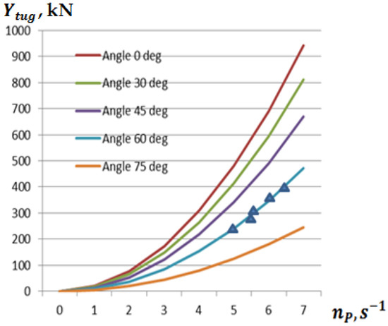
Figure 8.
The pulling force of two tugboats during side towing depending on the angle of the towing lines between the tugboats and the towed vessel (theoretical calculations of the lines; triangles—the pulling force of the tugboats obtained during experiments).
Thus, depending on the angle of the towing rope between the tugboat and the ship, and the frequency of rotation of the tugboat propellers, the pulling force of the tugboats varies several times. This must be compared with the external impact forces and the forces created by the tugboat propellers.
When mooring ships to the quay in particularly restrictive conditions, when tugboats perform side towing, it is necessary to maintain a minimum speed of the ship’s movement to the quay or when pulling the ship away from the quay [40,45]. For the studies, a minimum speed of lateral movement of the ship of about 0.05 m/s and 0.1 m/s was adopted, which allows damage to the quay fenders to be avoided regardless of whether the ship contacts one or more fenders.
Using the methodology presented in Chapter 3, we investigated the hydrodynamic forces created by the propeller flows of tugboats acting on a mooring ship moving at a minimum speed (in this case, the lateral speed of the ship was assumed to be 0.05 m/s), using side towing, as well as the pulling forces of two tugboats using 85% of the power of their main engines, with the tow rope angle between the tugboat and the towed ship being 45° (Figure 9).
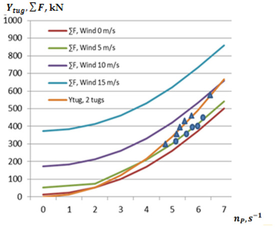
Figure 9.
The force required to tow or hold the ship at a POST PANAMAX ship lateral speed of 0.05 m/s, at different crosswind speeds and the pulling force of tugboats at tow rope angles of 45°, obtained theoretically and experimentally on real ships (triangles—pulling force of tugs, circles—total drag force of the ship hull).
At higher lateral speeds of moored ships, which can be adapted to the ship mooring conditions [40,45], similar conditions were studied with the same ships (POST PANAMAX bulk ship) and the same tugs (maximum pulling force 500 kN). When applying the side towing principle under extremely limited ship berthing conditions, the parameters of the ship resistance and the tugboat’s pulling force, when the lateral speed is about 0.1 m/s, are presented in Figure 10.
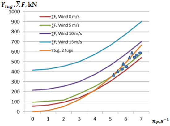
Figure 10.
Ship towing capabilities using the side towing method and ship‘s lateraling speed is 0.1 m/s when the towing rope angle is 45°, obtained theoretically and experimentally (triangles—tugboat pulling force, circles—ship hull total drag force).
The experimental results obtained, which correlate well with theoretical calculations, prove that the developed methodology for mooring ships in extremely limited conditions using the side towing method can be applied to the studied ships in the case when the tugboat traction force is greater than the total sum of external influences and the reverse force of the propeller flow. Thus, it can be stated that at wind speeds above 10 m/s, when its angle to the quay is about 90°, and the towing rope angle is 45° or more, the use of the side towing method is limited. At higher wind speeds for the specified conditions, it is necessary to look for ways to reduce the towing rope angle or use, if possible, other towing methods.
When using the pull/push method for berthing ships in extremely confined conditions (Figure 4), the distance between the tugboat propellers and the hull of the towed ship increases compared to the side towing method, which reduces the force created by the tugboat propeller flows acting in the opposite direction of the ship’s towing. Theoretical and experimental studies on the mooring operations of the POST PANAMAX bulk carrier (length between perpendiculars about 215 m) using the push/pull method were carried out using two tugboats with a pull/push force of about 500 kN. The results of the studies, i.e., the total resistance of the moored ship, depending on the crosswind speed to the quay, the opposing forces created by the tugboat propeller flows to the ship’s motion and the effect of shallowing, are presented in Figure 11.
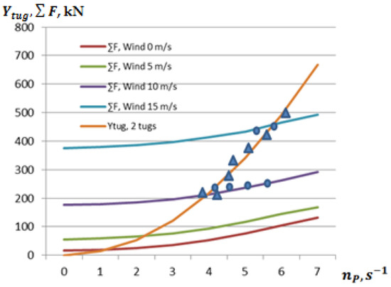
Figure 11.
Forces created by the ship’s lateral resistance and 2 tugs using the “Push/pull” method, depending on the crosswind speed and the angle of the towline 45°, obtained theoretically (lines) and experimentally (triangles—tugs’ pulling force, circles—ship’s hull’s total resistance force).
The efficiency of tugboats using the push/pull method during the berthing of ships at high current speeds towards the quay was also studied, since in practice similar situations were encountered in the port. In such cases, when it was necessary to pull the ship away from the quay, due to the limited water area, only the pull/push method could be used. There were cases when even using four tugboats it was not possible to pull the ship away from the quay and it was necessary to wait until the current speed decreased. Experiments were carried out with real PANAMAX and POST PANAMAX bulk carriers. Finally, the boundary conditions for performing such operations, i.e., the boundary current speeds, were obtained.
In the presence of current, wind, and the effect of the follow-up effect at the ship’s berthing location, using the methodology developed in Chapter 3, theoretical and experimental studies of the berthing of a POST PANAMAX bulk carrier in extremely limited conditions were carried out. During the studies, the wind speed was about 5 m/s towards the quay, the current direction was about 70° towards the quay, and the current speed was from 0.2 up to 0.6 m/s. The lateral speed of the ship was from 0.05 up to 0.1 m/s. Two tugboats were used in the mooring operation, each of which had a pulling/pushing force of about 500 kN. The results of the studies are presented in Figure 12 and Figure 13.
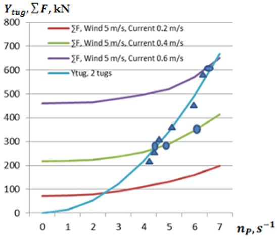
Figure 12.
Forces created by the ship’s lateral resistance (moored ships’ lateral speed 0.05 m/s), 2 tugs using the “Push/pull” method, depending on the crosswind speed and current from 0.2 m/s up to 0.6 m/s, the angle of the towline 45°, obtained theoretically (lines) and experimentally (triangles—tugs’ pulling force, circles—ship’s hull’s total resistance force).
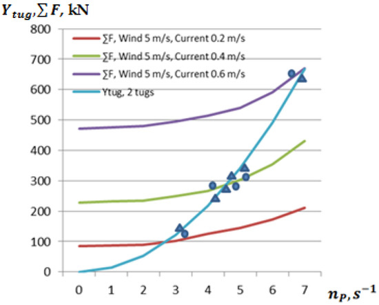
Figure 13.
Forces created by the ship’s lateral resistance (moored ship’s lateral speed 0.1 m/s), 2 tugs using the “Push/pull” method, depending on the crosswind speed and current from 0.2 m/s up to 0.6 m/s, the angle of the towline 45°, obtained theoretically (lines) and experimentally (triangles—tugs’ pulling force, circles—ship’s hull’s total resistance force).
The presented theoretical and experimental studies of the mooring of the POST PANAMAX vessel under extremely limited conditions using tugboats (Figure 9, Figure 10, Figure 11, Figure 12 and Figure 13) clearly showed that in the case when the pulling/pushing force of the tugboats is equal to or greater than the total resistance force of the moored vessel, the berthing operations of the vessel can be carried out safely. The power of the tugboats used in the studies was no more than 80–90%, in order to leave a reserve in case of any non-standard situations.
The obtained effect of the tugboat propeller flows on the hull of the moored vessel, depending on the propeller diameter and revolutions, clearly shows that when the tugboat propellers are close to the hull of the moored vessel, which corresponds to the side towing or pull/push methods, the optimal number of propeller revolutions or the angle of rotation of the propeller blades is of great importance during such an operation. Thus, the preliminary accurate determination of the propeller operating parameters directly influences the generated tugboat traction force and safe berthing operations of the vessel.
When using the pull/push method for berthing ships in extremely limited conditions, the current acting perpendicular to the quay (pier) has the greatest influence. The results of the research have shown that for the studied ships, at wind speeds up to 15 m/s (in many ports, at wind speeds of 15 m/s or more, ship mooring operations are limited), the possible maximum current speed to the quay (pier) may not exceed 0.5–0.6 m/s.
Berthing operations performed under extremely limited conditions have shown that, for a very small distance between the tugboat propellers and the ship’s hull, the tugboat propeller flow creates opposing forces that depend on the intensity of the flows. By regulating the intensity of the tugboat propeller flows in this way, it is possible to achieve relatively maximum forces when leading ships away from the quays or reducing the speed of ships approaching the quays. The resulting maximum conditional tugboat traction forces must be greater than the aerodynamic and other external forces acting on the ships in such situations in order to achieve the required ship berthing parameters (ship approach speed to the quay).
In this way, studies were conducted to obtain the difference between the pulling force of two tugboats and the lateral motion (resistance) force of the ship, at a lateral motion speed of the mooring ship of 0.05 m/s and 0.1 m/s, and with a wind direction towards the quay, the windspeed was about 5 m/s. The power of the tugboats used was about 85–90%, and the angle of the towing line was about 30° and 45°. The results of the studies are presented in Figure 14.
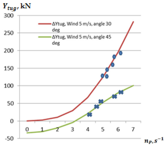
Figure 14.
The difference between the pulling force of two tugboats and the lateral motion force of the ship, when the lateral speed of the POST PANAMAX ship is 0.05 m/s and the lateral wind speed is 5 m/s, obtained theoretically and experimentally (−50 kN means opposite force).
The obtained results of the useful pulling force of tugboats, presented in Figure 14, are important in planning ship berthing operations in particularly limited port areas. This allows, using the methodology developed in Chapter 3, to accurately assess in advance the necessary pulling forces of tugboats and the conditions for successful berthing operations in similar conditions.
The developed methodology, compared to existing ones, allows for a more accurate assessment of ship berthing possibilities in extremely limited conditions. In the absence of sufficiently accurate information about ship berthing possibilities in extremely limited conditions, ports often wait for better hydrometeorological and hydrological conditions or unreasonably increase the risk of ship incidents in similar conditions. For example, in the conditions indicated in Figure 1, in order to enter or exit a ship, when the wind is acting on the quay, either ideal hydrometeorological conditions are expected, or a ship located at another quay is waited for. The methodology developed in this way allows for an increase in shipping safety and a reduction in ship downtime.
Theoretical and experimental studies have confirmed that the developed tugboat assessment methodology (presented in Chapter 3) is sufficiently accurate and can be successfully used in ports with limited water areas or other restrictive conditions.
5. Discussions and Conclusions
Theoretical and experimental studies were conducted with real ships and a calibrated simulator to berth ships under extremely limited conditions, and the results clearly showed that the developed methodology is acceptable for performing safe ship berthing operations under similar conditions. Based on the studies conducted, it can be stated that before starting ship berthing operations, it is very important to estimate the required tugboat pulling forces as accurately as possible, because inaccurate estimation of the required tugboat pulling forces and the number of tugboats may result in dangerous or non-standard situations. If non-standard situations arise during ship berthing, it is very difficult, and in some cases even impossible, to change such a situation, especially when there is a lack of tugboat pulling forces (capacity) [46,47]. At the same time, the competence of people participating in ship berthing operations (captains of moored ships, port pilots, and port tugboat captains) is one of the most important elements for the safe performance of such operations [48,49,50].
At the same time, it has been observed that a significant number of ship captains and port pilots often over-insure themselves due to their inability to accurately assess the capabilities of the ship and port tugs. While ensuring the safety of ship mooring operations, such an approach unnecessarily wastes additional resources, and in some cases limits the ability to use the services of tugs in other parts of the port where tug services are required, especially in very difficult hydrometeorological conditions in the port [48,49,50]. Thus, an accurate assessment of the necessary tugboat capacities, especially when performing ship berthing operations in extremely limited conditions, is very important.
The presented study of the method of ship berthing in ports under extremely limited conditions fills a gap in this area; i.e., it allows for an accurate assessment of the necessary tug capacities (traction forces) for a successful berthing operation while also improving the push/pull methods used.
The research conducted on ship berthing in very limited conditions in the port revealed additional problems, such as the need to flexibly select towing principles in extremely limited port conditions. At the same time, changing the working principles of tugboats (using side towing and push/pull principles) and the vertical angles of the towing rope (adapting to the structural features of the moored ship), using the maximum capabilities of modern port tugboats [51,52], and using new tug rope lines [53] should be directions for further research.
The advantage of the developed method of berthing ships in extremely limited conditions is the possibility of more accurately assessing the pulling forces actually created by tugboats operating near the side of the moored ship. It should be emphasized that this method of using tugboats (“side” towing) requires the installation of additional fenders at the sides of the tugboats to reduce the likelihood of damage to the hull of the moored ship.
During these studies, it was also noted that the new generation of ship crews and port tug specialists have mastered information technologies extremely well, but often “forget” the peculiarities of theoretical mechanics, hydrodynamics, and other subjects, which is also important when studying various peculiarities and capabilities of ship manoeuvring in extremely limited conditions, which is why the capabilities of modern port tugs are sometimes not used.
In conclusion, it can be stated that the developed ship berthing methodology, using the capabilities of port tugs under extremely limited conditions, has been tested on real ships and port tugs and, using calibrated simulators, can be successfully applied in various ports and other extremely limited ship manoeuvring areas.
Author Contributions
Conceptualization, V.P.; methodology, V.P. and D.P.; software, V.P. and D.P.; validation, V.P.; formal analysis, V.P. and D.P.; investigation, V.P.; resources, V.P. and D.P.; data curation, D.P.; writing—original draft preparation, V.P. and D.P.; writing—review and editing, D.P.; visualization, D.P.; supervision, V.P.; project administration, V.P.; funding acquisition, V.P. All authors have read and agreed to the published version of the manuscript.
Funding
This research received no external funding.
Institutional Review Board Statement
Not applicable.
Informed Consent Statement
Not applicable.
Data Availability Statement
Data are contained within the article.
Acknowledgments
This article is based on the research conducted by the Maritime Engineering Department of Klaipeda University.
Conflicts of Interest
The authors declare no conflicts of interest.
References
- Galor, W.; Kornacki, J. Analysis of Ships Turn Manoeuvres in Port Water Area. TransNav—Int. J. Mar. Navig. Saf. Sea Transp. 2007, 1, 95–100. [Google Scholar]
- Toma, A.; Oncica, V.; Atodiresei, D. The study of ships behavior during port maneuvering with tugs. Sci. Bull. Nav. Acad. 2016, 19, 109–115. [Google Scholar] [CrossRef]
- Sakai, T. Geographical Study on the Development of Port Space at Kushiro Port. J. Geogr. 2002, 111, 100–117. [Google Scholar] [CrossRef]
- Piaggio, B.; Viviani, M.; Martelli, M.; Figari, M. Z-Drive Escort Tug manoeuvrability model and simulation. Ocean Eng. 2019, 191, 106461. [Google Scholar] [CrossRef]
- Paulauskas, V.; Simutis, M.; Placiene, B.; Barzdžiukas, R.; Jonkus, M.; Paulauskas, D. The Influence of Port Tugs on Improving the Navigational Safety of the Port. J. Mar. Sci. Eng. 2021, 9, 342. [Google Scholar] [CrossRef]
- Çağrı, A.; Oral, Ü.U.; Karabulut, U.C.; Sarıöz, K. Practical Computational Procedures for Predicting Steering and Braking Forces of Escort Tugs. Ocean Eng. 2018, 166, 159–171. [Google Scholar] [CrossRef]
- Artyszuk, J. Types and Power of Harbour Tugs—the Latest Trends. Pr. Nauk. Politech. Warsz. 2013, 98, 12. [Google Scholar]
- Aro, E.; Rytter, N.G.M.; Itälinna, T. Maritime Industry Processes in the Baltic Sea Region; Annual Overview of Marine Casualties and Incidents 2023 European Maritime Safety Agency no. June: 1–66; European Maritime Safety Agency: Lisbon, Portugal, 2023.
- Klaipeda Seaport Manual, Maps and Charts. 2025. Available online: www.portofklaipeda.lt (accessed on 25 February 2025).
- Rotterdam Port Manuel, Maps and Charts. 2025. Available online: https://www.portofrotterdam.com/en (accessed on 25 February 2025).
- Antwerp Port Manuel, Maps and Charts. 2025. Available online: https://www.portofantwerp.com/en (accessed on 25 February 2025).
- Bremen port Manuel, Maps and Charts. 2025. Available online: https://www.portofbremen.com/en (accessed on 25 February 2025).
- Port of Roterdam Ongoing Projects. 2025. Available online: https://www.portofrotterdam.com/en/building-port/ongoing-projects (accessed on 28 February 2025).
- Port of Zeebruge. 2025. Available online: https://www.zeebruge.com/en (accessed on 25 February 2025).
- Mazaheri, A.; Montewka, J.; Kotilainen, P.; Sormunen, O.V.E.; Kujala, P. Assessing Grounding Frequency Using Ship Traffic and Waterway Complexity. J. Navig. 2015, 68, 89–106. [Google Scholar] [CrossRef]
- Guan, H.; Xu, Y.; Li, L.; Huang, X. Optimizing Lock Operations and Ship Arrivals through Multiple Locks on Inland Waterways. Math. Probl. Eng. 2021, 2021, 6220559. [Google Scholar] [CrossRef]
- Carral, L.; Tarrio-Saavedra, J.; Castro-Santos, L.; Lamas-Galdo, I.; Sabonge, R. Effects of the Expanded Panama Canal on Vessel Size and Seaborne Transport. Promet—Traffic Transp. J. 2018, 30, 241–251. [Google Scholar] [CrossRef]
- Carral, L.; Tarrío-Saavedra, J.; Naya, S.; Bogle, J.; Sabonge, R. Effect of inaugurating the third set of locks at the Panama Canal on vessel size, manoeuvring and lockage time. J. Navig. 2017, 70, 1205–1223. [Google Scholar] [CrossRef]
- Andersen, T.; Høgset Hove, J.; Fagerholt, K.; Meisel, F. Scheduling ships with uncertain arrival times through the Kiel Canal. Marit. Transp. Res. 2021, 2, 100008. [Google Scholar] [CrossRef]
- Lübbecke, E.; Lübbecke, M.E.; Möhring, R.H. Ship Traffic Optimization for the Kiel Canal. Oper. Res. 2019, 67, 791–812. [Google Scholar] [CrossRef]
- Port of Venice Manuel, Maps and Charts. 2025. Available online: https://www.port.venice.it/en/?doing_wp_cron=1738664528.9866020679473876953125 (accessed on 24 February 2025).
- Port of Helsinki Manuel, Maps and Charts. 2025. Available online: https://www.portofhelsinki.fi/en/ (accessed on 24 February 2025).
- AIS. Available online: https://www.marinetraffic.com/en/ais/home/centerx:21.146/centery:55.656/zoom:15 (accessed on 15 January 2025).
- Paulauskas, V.; Paulauskas, D. Research on work methods for tugs in ports. Transport 2011, 26, 310–314. [Google Scholar] [CrossRef]
- Kozioł, W.; Galor, W. Some Problems of Berthing of Ships with Non-conventional Propulsions. Int. J. Mar. Navig. Saf. Sea Transp. 2007, 1, 319–323. [Google Scholar]
- Chou, C.C.; Wen, C.-C.; Huang, Y.-Y. Analysis of Tugboat Operation and Towage Fees in a Taiwanese Port and Alternatives for Improving Tugboat Operation by the Delphi Method. J. Eng. Marit. Environ. 2021, 235, 176–187. [Google Scholar] [CrossRef]
- Kang, L.; Gao, S.; Meng, Q. Capacity Analysis of Ship-Tugging Operations in a Large Container Port. Asian Transp. Stud. 2020, 6, 100011. [Google Scholar] [CrossRef]
- Chauhan, S.; Patil, C.; Sinha, M.; Halder, A. Fuzzy state noise-driven Kalman filter for sensor fusion. J. Aerosp. Eng. 2009, 223, 1091–1097. [Google Scholar] [CrossRef]
- Jin, H.; Peng, S. Optimal unbiased estimation for maximal distribution. PUQR 2021, 6, 189–198. [Google Scholar] [CrossRef]
- Specht, C. Maritime DGPS System Positioning Accuracy as a Function of the HDOP in the Context of Hydrographic Survey Performance. Remote Sens. 2023, 15, 10. [Google Scholar] [CrossRef]
- Alissa, S.; Håkansson, M.; Henkel, P.; Mittmann, U.; Hüffmeier, J.; Rylander, R. Low bandwidth network-RTK correction dissemination for high accuracy maritime navigation. TransNav—Int. J. Mar. Navig. Saf. Sea Transp. 2021, 15, 171–179. [Google Scholar] [CrossRef]
- Gucma, L.; Montewka, J. Land borne laser rangefinder measurements for navigation safety assessment. Eur. J. Navig. 2005, 3, 1–6. [Google Scholar]
- Gucma, L. The Risk Assessment of Ships Maneuvering on the Waterways Based on Generalized Simulation. DataWIT Trans. Built Environ. 2007, 94, 58–69. [Google Scholar]
- “SimFlex Navigator” Simulator in Klaipeda University, Force Technology, Denmark, (License No 159 2016.09.20); Manuel “SimFlex Navigator”; Forse Technology: Copenhagen, Denmark, 2014; 68p.
- Feeny, B.F. D’Alembert’s Principle and the Equations of Motion for Nonholonomic Systems. In Proceedings of the ASME 2006 International Mechanical Engineering Congress and Exposition (IMECE2006), Chicago, IL, USA, 5–10 November 2006; pp. 561–570. [Google Scholar] [CrossRef]
- Rawson, K.J.; Tupper, E.C. Basic Ship Theory, 5th ed.; Elsever: Amsterdam, The Netherlands, 2001; 727p. [Google Scholar]
- Perkovič, M. Advances in Navigability and Mooring. J. Mar. Sci. Eng. 2024, 12, 1601. [Google Scholar] [CrossRef]
- Čerka, J. Laivo Eigumas; Klaipeda University Publish House: Klaipeda, Lithuania, 2005; 200p. (In Lithuanian) [Google Scholar]
- Kianejad, S.S.; Enshaei, H.; Duffy, J.; Ansarifard, N. Prediction of a ship roll added mass moment of inertia using numerical simulation. Ocean Eng. 2019, 173, 77–89. [Google Scholar] [CrossRef]
- PIANC Fender Guidelines 2024, Guidelines for the Design, Manufacturing and Testing of Fender Systems; PIANC: Brussels, Belgium, 2024; 274p, ISBN 978-2-87223-036-5.
- EAU 2016: Recommendations of the Committee for Waterfront Structures—Harbours and Waterways; Wiley: Hoboken, NJ, USA, 2016.
- Puertos del Estado. ROM 3.1-99: Recommendations for the Design of the Maritime Configuration of Ports, Approach Channels and Harbour Basins; Puertos del Estado: Madrid, Spain, 1999; 350p. [Google Scholar]
- Feng, G.; Yougang, T.; Chuanqi, H.; Xiaolei, X. Research on a Ship Mooring Motion Suppression Method Based on an Intelligent Active Anti-Roll Platform. Appl. Sci. 2023, 13, 7979. [Google Scholar] [CrossRef]
- Nitonye, S.; Sidum, A.; Howells, U.U. Numerical Design and Performance Analysis of a Tug Boat Propulsion System. J. Power Energy Eng. 2017, 5, 80–98. [Google Scholar] [CrossRef]
- Choi, J.-H.; Jang, J.-Y.; Woo, J. A Review of Autonomous Tugboat Operations for Efficient and Safe Ship Berthing. J. Mar. Sci. Eng. 2023, 11, 1155. [Google Scholar] [CrossRef]
- Wu, G.; Zhao, X.; Sun, Y.; Wang, L. Cooperative Maneuvering Mathematical Modeling for Multi-Tugs Towing a Ship in the Port Environment. J. Mar. Sci. Eng. 2021, 9, 384. [Google Scholar] [CrossRef]
- Brooks, G.; Slough, S.W. The Utilization of Escort Tugs in Restricted Waters, 9th ed.; Port Technology International: London, UK, 2001; pp. 221–229. Available online: http://www.towingsolutionsinc.com (accessed on 25 February 2025).
- Smoker, B.; Stockdill, B.; Oshkai, P. Escort Tug Performance Prediction Using Computational Fluid Dynamics. J. Ship Res. 2016, 60, 61–77. [Google Scholar] [CrossRef]
- Yıldırım, U.; Başar, E.; Uğurlu, Ö. Assessment of collisions and grounding accidents with human factors analysis and classification system (HFACS) and statistical methods. Saf. Sci. 2019, 119, 412–425. [Google Scholar] [CrossRef]
- Weintrit, A. Initial description of pilotage and tug services in the context of e-navigation. J. Mar. Sci. Eng. 2020, 8, 116. [Google Scholar] [CrossRef]
- Doğan, S.Ö. Propeller design and verification studies for 30–35 meter tugboats. J. Radiat. Res. Appl. Sci. 2023, 16, 100740. [Google Scholar] [CrossRef]
- Liu, W.; Liu, Z.; Chen, Q.; Ma, C. Research on efficiency optimization of the voith-schneider propeller based on motion curve parameter control. Ocean Eng. 2024, 299, 117136. [Google Scholar] [CrossRef]
- Carral, L.; Fraguela, J.A.; De Troya, J.; Álvarez-Feal, C. Influence of the towline material: Steel or high-modulus polyethylene on towing gear design and tug deck fittings. Proc. Inst. Mech. Eng. Part M J. Eng. Marit. Environ. 2015, 230, 639–651. [Google Scholar] [CrossRef]
Disclaimer/Publisher’s Note: The statements, opinions and data contained in all publications are solely those of the individual author(s) and contributor(s) and not of MDPI and/or the editor(s). MDPI and/or the editor(s) disclaim responsibility for any injury to people or property resulting from any ideas, methods, instructions or products referred to in the content. |
© 2025 by the authors. Licensee MDPI, Basel, Switzerland. This article is an open access article distributed under the terms and conditions of the Creative Commons Attribution (CC BY) license (https://creativecommons.org/licenses/by/4.0/).