
Application of Microbial Technology for Enhancing Carbon Dioxide Geosequestration in Shallow Seabed Caprock


Abstract
1. Introduction
2. Materials and Methods
2.1. Materials
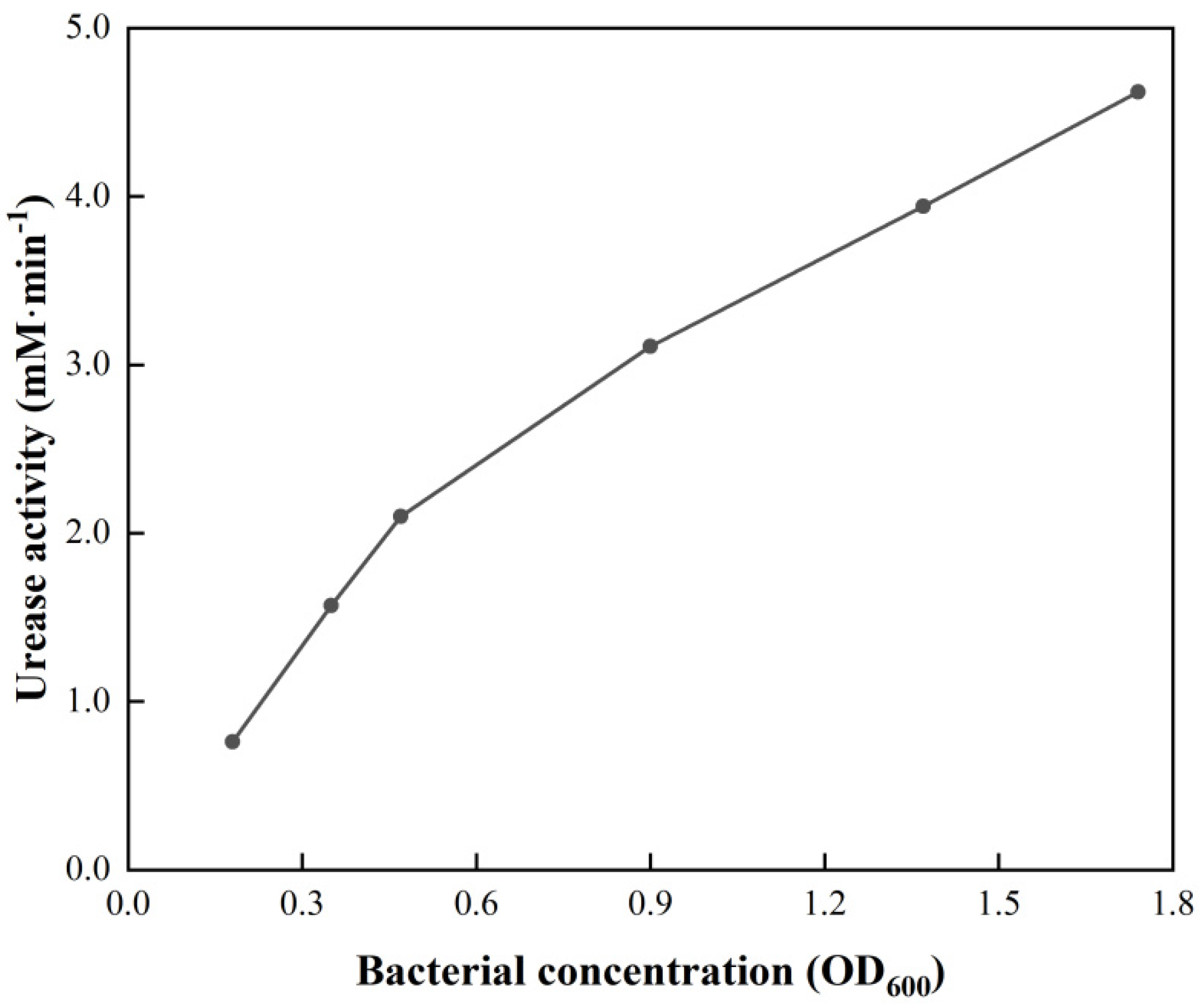
2.1.1. Bacteria
2.1.2. Carbon Dioxide
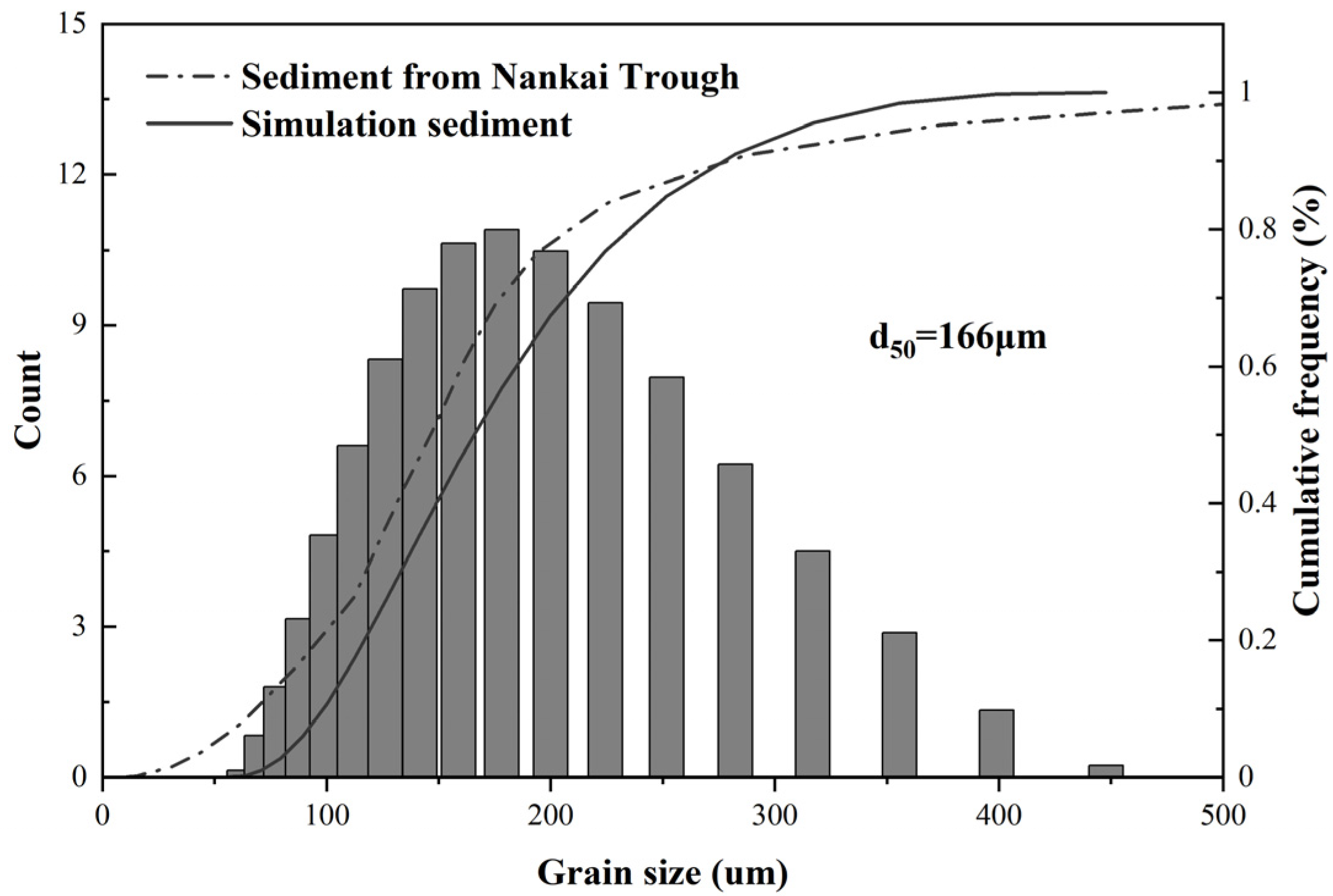
2.1.3. Sediment
2.2. Test Procedures
2.2.1. Carbon Sequestration Test
2.2.2. Triaxial Test
2.2.3. XRD, SEM, and CT
3. Results
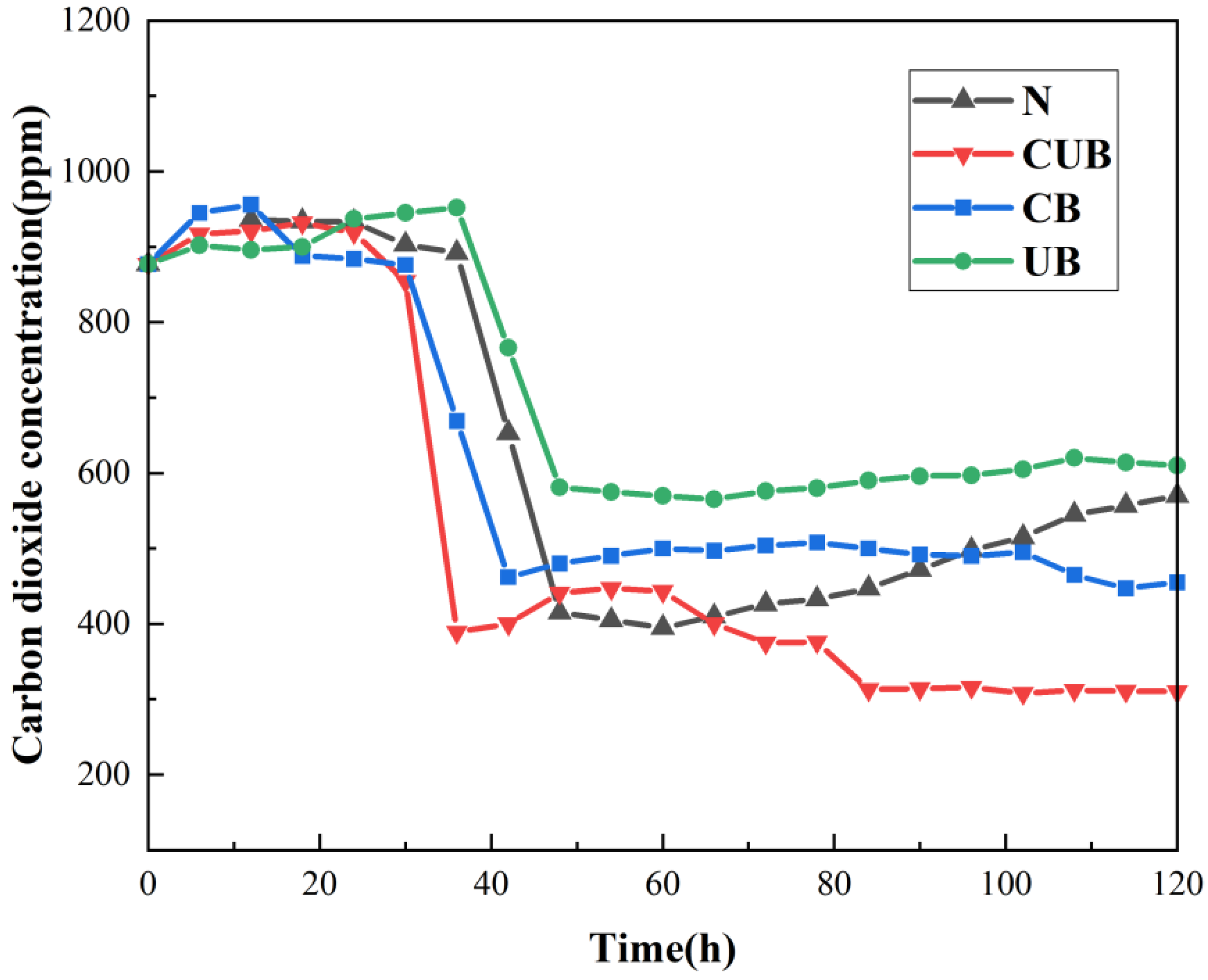
3.1. Evolution Law of CO2 Concentration
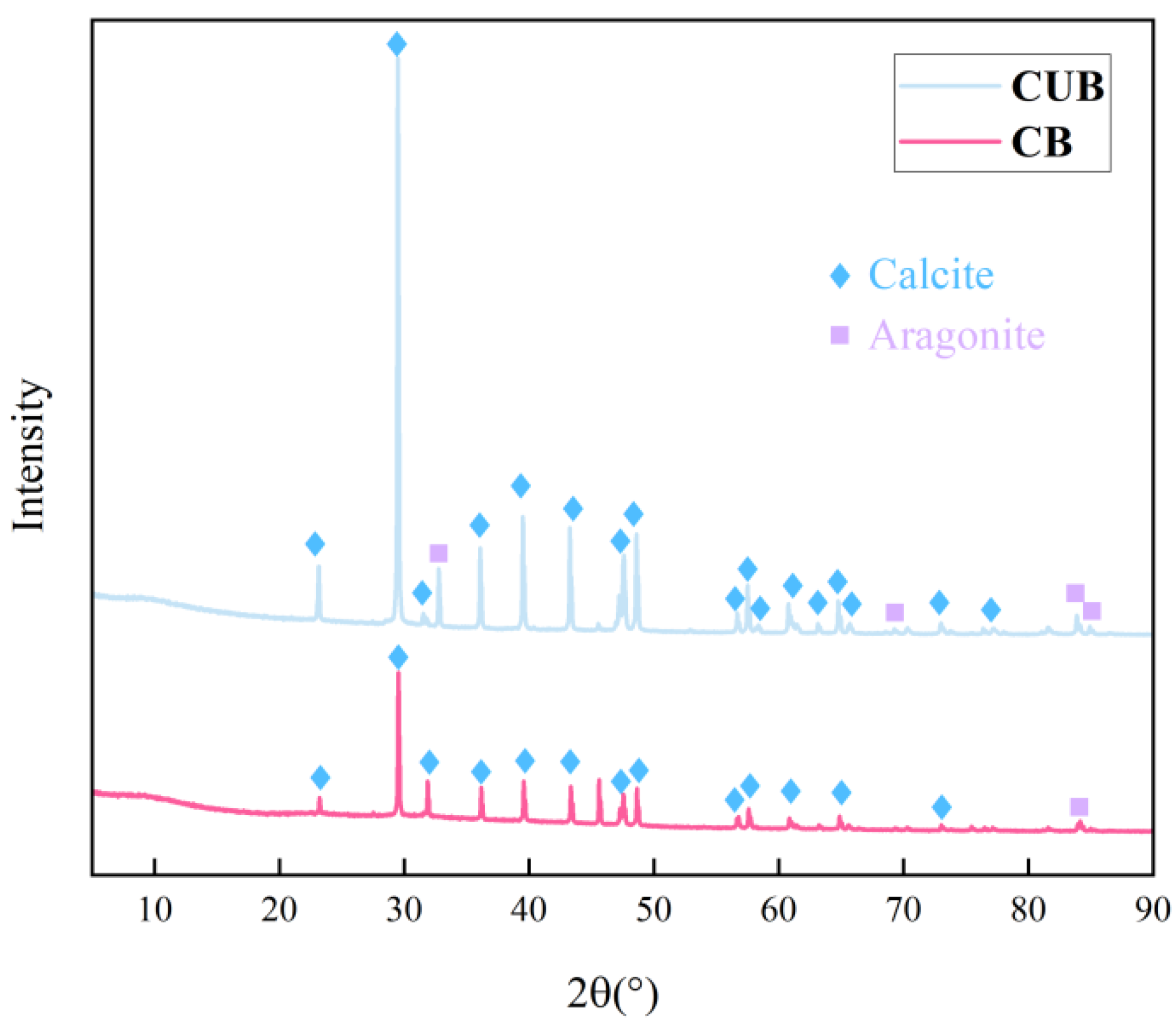
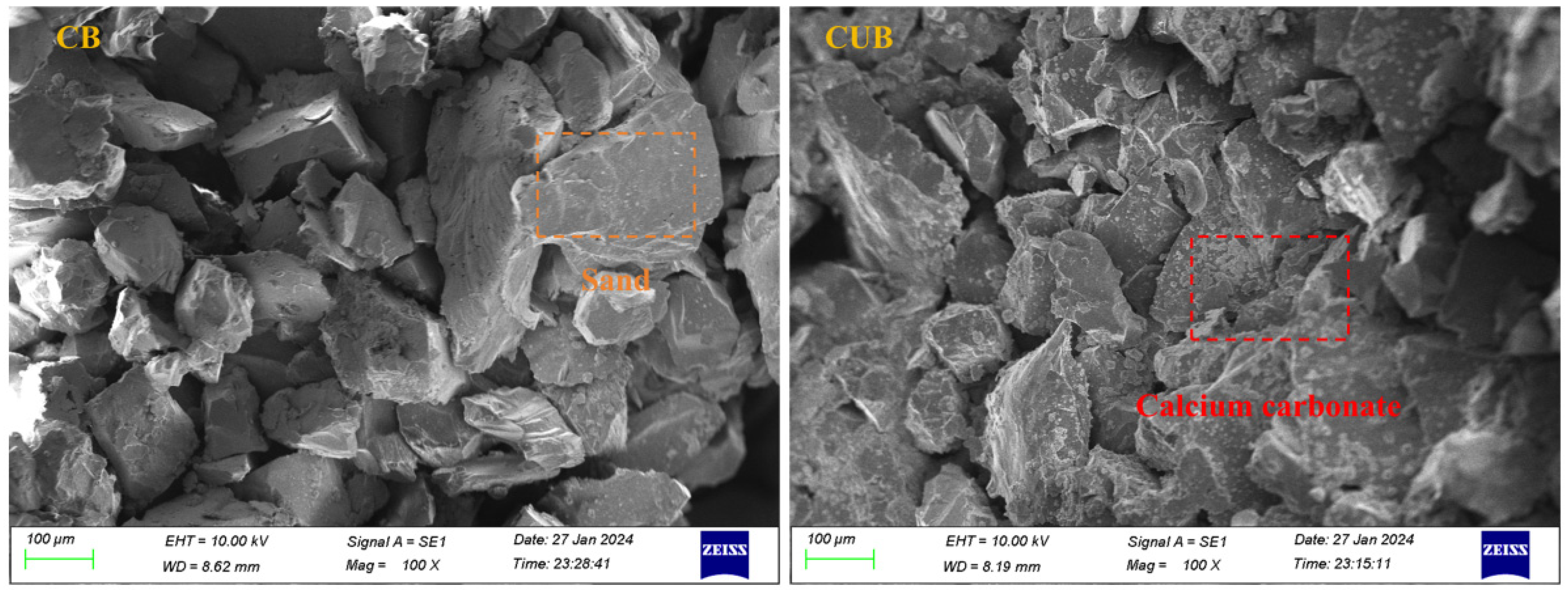
3.2. Microstructure of Particles Formed by Carbon Sequestration
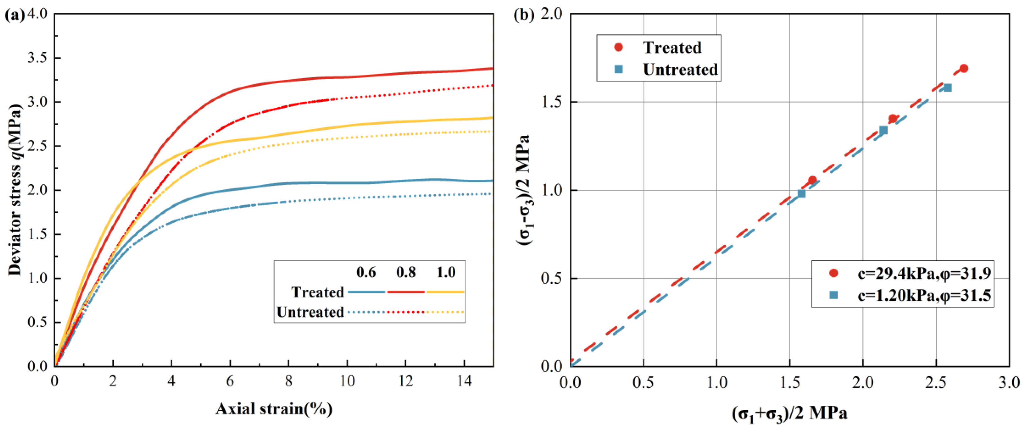
3.3. Reinforcement Effect
3.4. Sealing Property
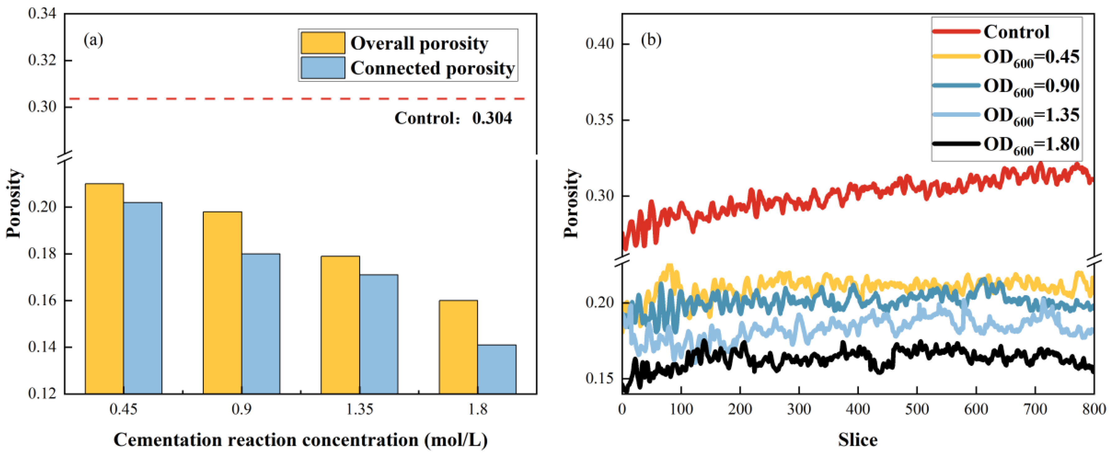
3.4.1. Cementation Reaction Fluid Concentration
3.4.2. Bacterial Suspension Concentration
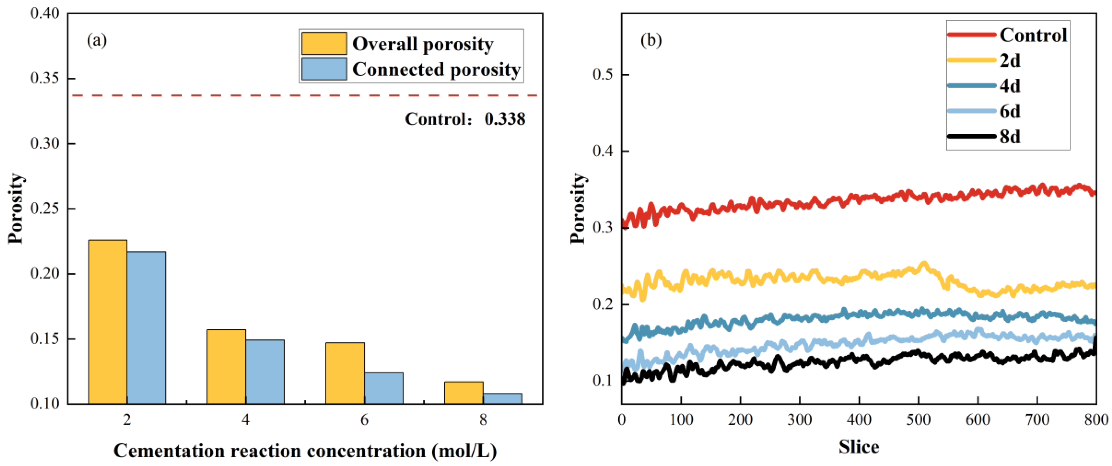
3.4.3. Treatment Duration
4. Discussion
4.1. The Mechanism to Improve the Sequestration Capability
4.2. The Role of Urea and Ca2+ in Accelerated Mineralization
4.3. Significance and Limitations
5. Conclusions
Author Contributions
Funding
Data Availability Statement
Conflicts of Interest
References
- Jepma, C.J.; Munasinghe, M. Climate Change Policy: Facts, Issues and Analyses; Cambridge University Press: Cambridge, UK, 1998. [Google Scholar]
- Kamal, N.; Itam, Z.; Sivaganese, Y.; Razak, N.A. Carbon Dioxide Sequestered Concrete. Int. J. Integr. Eng. 2020, 12, 45–51. [Google Scholar]
- Kelemen, P.; Benson, S.M.; Pilorgé, H.; Psarras, P.; Wilcox, J. An Overview of the Status and Challenges of CO2 Storage in Minerals and Geological Formations. Front. Clim. 2019, 1, 9. [Google Scholar] [CrossRef]
- Martin-Roberts, E.; Scott, V.; Flude, S.; Johnson, G.; Haszeldine, R.S.; Gilfillan, S. Carbon capture and storage at the end of a lost decade. One Earth 2021, 4, 1569–1584. [Google Scholar] [CrossRef]
- Patra, B.R.; Mukherjee, A.; Nanda, S.; Dalai, A.K. Biochar production, activation and adsorptive applications: A review. Environ. Chem. Lett. 2021, 19, 2237–2259. [Google Scholar] [CrossRef]
- Hussin, F.; Aroua, M.K. Recent advances in low-temperature electrochemical conversion of carbon dioxide. Rev. Chem. Eng. 2021, 37, 863–884. [Google Scholar] [CrossRef]
- Francis, J.C.; Nighojkar, A.; Kandasubramanian, B. Relevance of wood biochar on CO2 adsorption: A review. Hybrid Adv. 2023, 3, 100056. [Google Scholar]
- Dixit, F.; Zimmermann, K.; Alamoudi, M.; Abkar, L.; Barbeau, B.; Mohseni, M.; Kandasubramanian, B.; Smith, K. Application of MXenes for air purification, gas separation and storage: A review. Renew. Sustain. Energy Rev. 2022, 164, 112527. [Google Scholar] [CrossRef]
- Liu, J.; Baeyens, J.; Deng, Y.; Tan, T.; Zhang, H. The chemical CO2 capture by carbonation-decarbonation cycles. J. Environ. Manag. 2020, 260, 110054. [Google Scholar] [CrossRef]
- Zhou, T.; Shi, H.; Ding, X.; Zhou, Y. Thermodynamic modeling and rational design of ionic liquids for pre-combustion carbon capture. Chem. Eng. Sci. 2021, 229, 116076. [Google Scholar]
- Krishnan, A.; Nighojkar, A.; Kandasubramanian, B. Emerging towards zero carbon footprint via carbon dioxide capturing and sequestration. Carbon Capture Sci. Technol. 2023, 9, 100137. [Google Scholar]
- Wong-Parodi, G.; Ray, I.; Farrell, A.E. Environmental non-government organizations’ perceptions of geologic sequestration. Environ. Res. Lett. 2008, 3, 024007. [Google Scholar] [CrossRef]
- Price, P.N.; Oldenburg, C.M. The consequences of failure should be considered in siting geologic carbon sequestration projects. Int. J. Greenh. Gas Control 2009, 3, 658–663. [Google Scholar] [CrossRef]
- Bachu, S. Sequestration of CO2 in geological media: Criteria and approach for site selection in response to climate change. Energ. Convers. Manag. 2000, 41, 953–970. [Google Scholar] [CrossRef]
- Dumitrache, L.N.; Suditu, S.; Ghețiu, I.; Pană, I.; Brănoiu, G.; Eparu, C. Using Numerical Reservoir Simulation to Assess CO2 Capture and Underground Storage, Case Study on a Romanian Power Plant and Its Surrounding Hydrocarbon Reservoirs. Processes 2023, 11, 805. [Google Scholar] [CrossRef]
- Suditu, S.; Dumitrache, L.; Brănoiu, G.; Prundurel, A.; Ghețiu, I. Carbon Capture and Storage Subsurface Study for a Natural Gas-Burning Power Plant in Oltenia, Romania. Processes 2024, 12, 1648. [Google Scholar] [CrossRef]
- Ndlovu, P.; Babaee, S.; Naidoo, P. Review on CH4-CO2 replacement for CO2 sequestration and CH4/CO2 hydrate formation in porous media. Fuel 2022, 320, 123795. [Google Scholar] [CrossRef]
- Striolo, A. Clathrate hydrates: Recent advances on CH4 and CO2 hydrates, and possible new frontiers. Mol. Phys. 2019, 117, 3556–3568. [Google Scholar] [CrossRef]
- Yan, C.L.; Ren, X.; Cheng, Y.F.; Song, B.J.; Li, Y.; Tian, W.Q. Geomechanical issues in the exploitation of natural gas hydrate. Gondwana Res. 2020, 81, 403–422. [Google Scholar] [CrossRef]
- Smyth, R.C.; Meckel, T.A. Best Management Practices for Subseabed Geologic Sequestration of Carbon Dioxide. In Proceedings of the 2012 Oceans, Hampton Roads, VA, USA, 14–19 October 2012. [Google Scholar]
- Al Qabany, A.; Soga, K. Effect of chemical treatment used in MICP on engineering properties of cemented soils. In Bio- and Chemo-Mechanical Processes in Geotechnical Engineering; ICE Publishing: London, UK, 2014; pp. 107–115. [Google Scholar]
- Tang, C.; Liu, T.; Fang, C.; Qin, S.; Yang, G.; Lei, G.; Sun, J. Experimental study of microbially induced carbonate precipitation treatment on seafloor sediment of hydrate formation. Acta Geotech. 2024, 19, 1597–1610. [Google Scholar] [CrossRef]
- Liu, B.; Zhu, C.; Tang, C.S.; Xie, Y.H.; Yin, L.Y.; Cheng, Q.; Shi, B. Bio-remediation of desiccation cracking in clayey soils through microbially induced calcite precipitation (MICP). Eng. Geol. 2020, 264, 105389. [Google Scholar] [CrossRef]
- Wang, Z.; Liu, T.; Yang, G.; Zhao, S. Preparation and research on cationic modified vermiculite with strong adsorption capacity for mineralizing bacteria. Mater. Lett. 2024, 363, 136313. [Google Scholar] [CrossRef]
- Qin, S.; Sun, J.; Liu, T.; Tang, C.; Lei, G.; Dou, X.; Gu, Y. Sand control during gas production from marine hydrate reservoirs by using microbial-induced carbonate precipitation technology: A feasibility study. Energy 2024, 299, 131494. [Google Scholar] [CrossRef]
- Khormali, A.; Petrakov, D.G.; Farmanzade, A.R. Prediction and Inhibition of Inorganic Salt Formation Under Static and Dynamic Conditions—Effect of Pressure, Temperature, and Mixing Ratio. Int. J. Technol. 2016, 7, 943. [Google Scholar] [CrossRef]
- Dhami, N.K.; Mukherjee, A.; Reddy, M.S. Micrographical, minerological and nano -mechanical characterisation of microbial carbonates from urease and carbonic anhydrase producing bacteria. Ecol. Eng. 2016, 94, 443–454. [Google Scholar] [CrossRef]
- Gilmour, K.A.; Ghimire, P.S.; Wright, J.; Haystead, J.; Dade-Robertson, M.; Zhang, M.; James, P. Microbially induced calcium carbonate precipitation through CO2 sequestration via an engineered Bacillus subtilis. Microb. Cell Factories 2024, 23, 168. [Google Scholar] [CrossRef]
- Kaur, G.; Dhami, N.K.; Goyal, S.; Mukherjee, A.; Reddy, M.S. Utilization of carbon dioxide as an alternative to urea in biocementation. Constr. Build. Mater. 2016, 123, 527–533. [Google Scholar] [CrossRef]
- Bains, A.; Dhami, N.K.; Mukherjee, A.; Reddy, M.S. Influence of Exopolymeric Materials on Bacterially Induced Mineralization of Carbonates. Appl. Biochem. Biotech. 2015, 175, 3531–3541. [Google Scholar] [CrossRef]
- Dhami, N.K.; Reddy, M.S.; Mukherjee, A. Synergistic Role of Bacterial Urease and Carbonic Anhydrase in Carbonate Mineralization. Appl. Biochem. Biotech. 2014, 172, 2552–2561. [Google Scholar] [CrossRef]
- Whiffin, V.S. Microbial CaCO3 Precipitation for the Production of Biocement. Ph.D. Thesis, Murdoch University, Murdoch, WA, Australia, 2004. [Google Scholar]
- Hyodo, M.; Li, Y.; Yoneda, J.; Nakata, Y.; Yoshimoto, N.; Nishimura, A. Effects of dissociation on the shear strength and deformation behavior of methane hydrate-bearing sediments. Mar. Pet. Geol. 2014, 51, 52–62. [Google Scholar] [CrossRef]
- Gu, Y.; Sun, J.; Qin, F.; Ning, F.; Cao, X.; Liu, T.; Qin, S.; Zhang, L.; Jiang, G. Enhancing gas recovery from natural gas hydrate reservoirs in the eastern Nankai Trough: Deep depressurization and underburden sealing. Energy 2023, 262, 125510. [Google Scholar] [CrossRef]
- Clough, G.W.; Sitar, N.; Bachus, R.C.; Rad, N.S. Cemented sands under static loading. J. Geotech. Eng. Div. 1981, 107, 799–817. [Google Scholar] [CrossRef]
- Cui, H.; Xiao, Y.; Sun, Z.C.; Wang, C.; Liang, F.; Liu, H.L. Elastoplastic constitutive model for biocemented sands. Chin. J. Geotech. Eng. 2022, 44, 474–482. [Google Scholar]
- Van Wijngaarden, W.K.; Van Paassen, L.A.; Vermolen, F.J.; Van Meurs, G.; Vuik, C. A reactive transport model for biogrout compared to experimental data. Transp. Porous Media 2016, 111, 627–648. [Google Scholar] [CrossRef]


| Column | CaCl2 | Urea | Bacteria |
|---|---|---|---|
| N | − | − | − |
| CUB * | + | + | + |
| CB * | + | − | + |
| UB * | − | + | + |
Disclaimer/Publisher’s Note: The statements, opinions and data contained in all publications are solely those of the individual author(s) and contributor(s) and not of MDPI and/or the editor(s). MDPI and/or the editor(s) disclaim responsibility for any injury to people or property resulting from any ideas, methods, instructions or products referred to in the content. |
© 2025 by the authors. Licensee MDPI, Basel, Switzerland. This article is an open access article distributed under the terms and conditions of the Creative Commons Attribution (CC BY) license (https://creativecommons.org/licenses/by/4.0/).
Share and Cite
Xiong, L.; Tian, L.; Zhang, X.; Lv, Y.; Zhang, H. Application of Microbial Technology for Enhancing Carbon Dioxide Geosequestration in Shallow Seabed Caprock. J. Mar. Sci. Eng. 2025, 13, 574. https://doi.org/10.3390/jmse13030574
Xiong L, Tian L, Zhang X, Lv Y, Zhang H. Application of Microbial Technology for Enhancing Carbon Dioxide Geosequestration in Shallow Seabed Caprock. Journal of Marine Science and Engineering. 2025; 13(3):574. https://doi.org/10.3390/jmse13030574
Chicago/Turabian StyleXiong, Liang, Lieyu Tian, Xiaolian Zhang, Yang Lv, and Huiyin Zhang. 2025. "Application of Microbial Technology for Enhancing Carbon Dioxide Geosequestration in Shallow Seabed Caprock" Journal of Marine Science and Engineering 13, no. 3: 574. https://doi.org/10.3390/jmse13030574
APA StyleXiong, L., Tian, L., Zhang, X., Lv, Y., & Zhang, H. (2025). Application of Microbial Technology for Enhancing Carbon Dioxide Geosequestration in Shallow Seabed Caprock. Journal of Marine Science and Engineering, 13(3), 574. https://doi.org/10.3390/jmse13030574