Article

Accelerated Life Testing of Marine Electrical Insulation Systems Based on Frequency-Dependent Breakdown Analysis

Eco-Friendly Propulsion Headquarters, Korea Marine Equipment Research Institute, Ulsan 44776, Republic of Korea
J. Mar. Sci. Eng. 2025, 13(3), 500; https://doi.org/10.3390/jmse13030500
Submission received: 9 February 2025 / Revised: 26 February 2025 / Accepted: 3 March 2025 / Published: 4 March 2025
(This article belongs to the Section Ocean Engineering)

Abstract

:
Marine power systems, including generators and transformers, experience voltage stress at various frequencies. Once the stress exceeds the bearing capacity of the electrical system, it results in insulation breakdown or failure. Therefore, extensive testing is required to ensure that marine electrical insulation systems are reliable. In accordance with International Electrotechnical Commission (IEC) standards, conventional tests at commercial frequencies require over 5000 h, making them time-consuming, inefficient, and practically infeasible. This study explores frequency-based accelerated life testing to reduce the duration of testing. Insulation systems made of mica-based corona-resistant materials and epoxy resin were tested at 60, 300, 600, and 900 Hz using a variable-frequency high-voltage tester. The results show that the time to failure decreases as the frequency increases (from 381.83 h at 60 Hz to 22.33 h at 900 Hz, a 94% reduction). Power and exponential decay models effectively describe this relationship. The power model provides a better overall fit, and the exponential decay model improves the accuracy at higher frequencies. This study confirms that higher frequencies accelerate insulation degradation, shortening test times considerably. Frequency-based accelerated testing can enhance insulation system evaluation and optimize international testing standards.

1. Introduction

Electrical insulation systems play a crucial role in ensuring the reliability and longevity of power devices, particularly in marine power systems. However, evaluating their durability requires extensive and prolonged testing, which imposes challenges in terms of time, labor, and cost. In accordance with the Institute of Electrical and Electronics Engineers (IEEE) standard (IEEE Std 117-1974) and International Electrotechnical Commission (IEC) standard (IEC 60034-18-32), aging tests for electrical insulation systems need to be conducted for at least 5000 h (approximately 250 d) at the lowest voltage level and 200 h at the highest voltage level [1,2]. Such an extended testing duration limits the efficiency of insulation system evaluations and increases operational costs.
To address this problem, frequency-based accelerated life testing has been proposed as a means to drastically reduce testing time. IEC 60034-18-32 and IEC 60505 recognize the influence of frequency as a critical factor in insulation material degradation and suggest its incorporation into insulation durability evaluation methods [2,3]. The degradation of electrical insulation systems is primarily driven by a combination of electrical and thermal stresses, both of which are amplified at higher frequencies.
Previous research has confirmed that higher frequencies accelerate the failure mechanisms of insulation materials, resulting in shorter test durations. Dissado and Fothergill demonstrated that frequency strongly influences molecular structural changes and electron movement within insulation materials, which contribute to the degradation of insulation materials [4]. Lu et al. further highlighted that frequency and temperature are predominant factors that affect the lifespan of insulation materials [5]. Their findings demonstrated that higher frequencies in power systems amplify voltage stress, intensifying degradation [5].
Several studies have explored the feasibility of frequency-based accelerated testing. The effects of voltage and frequency variations on insulation material degradation have been extensively analyzed, with scholars confirming that test durations can be shortened by increasing frequency [5,6]. Zhang et al. [7] experimentally demonstrated that higher frequencies accelerate partial discharge, which in turn reduces the insulation failure time. Liu et al. [8] developed a quantitative model that describes the relationship between frequency variation and failure time through accelerated degradation simulations. Liang et al. [9] confirmed that higher-frequency environments result in faster degradation, further validating the potential of frequency-based accelerated testing to reduce testing durations. Additionally, empirical studies by Vocke and Moser and Zhang et al. [10,11] confirmed that high-frequency conditions improve the efficiency of insulation performance evaluations in real-world power systems.
Despite these findings, many previous studies have been limited to specific insulation materials under constrained frequency conditions, making it difficult to generalize their results to practical insulation system evaluations. Moreover, a lack of direct comparisons with international testing standards has hindered the widespread adoption of frequency-based accelerated life testing [12,13,14,15,16,17,18,19,20,21,22,23].
The objective of this study is to quantitatively analyze the effects of increasing frequency on the failure time of electrical insulation systems and assess the feasibility of reducing test durations using frequency-based accelerated life testing. Specifically, this study compares the required testing durations under different frequency conditions with those mandated by IEEE and IEC standards. Mathematical models are employed to validate the correlation between frequency and failure time, providing a more systematic approach to evaluating insulation systems.
Compared to previous frequency-based accelerated life testing studies [5,7,8], the approach adopted in this study is distinct in several aspects. While previous studies primarily focused on either partial discharge phenomena or general insulation materials, this study investigates mica-based corona-resistant materials combined with epoxy resin, specifically tailored for marine power systems. Additionally, the present study employs both power and exponential decay models simultaneously to systematically analyze frequency-dependent degradation, providing a robust and comprehensive understanding that surpasses the scope of previous studies.
Furthermore, experimental data are used to verify previous research findings and develop an efficient testing process that conforms to international standards. The results of this study contribute to the optimization of insulation system evaluation methodologies and the design of accelerated testing protocols, particularly for marine power systems where insulation reliability is a critical requirement.

2. Methodology

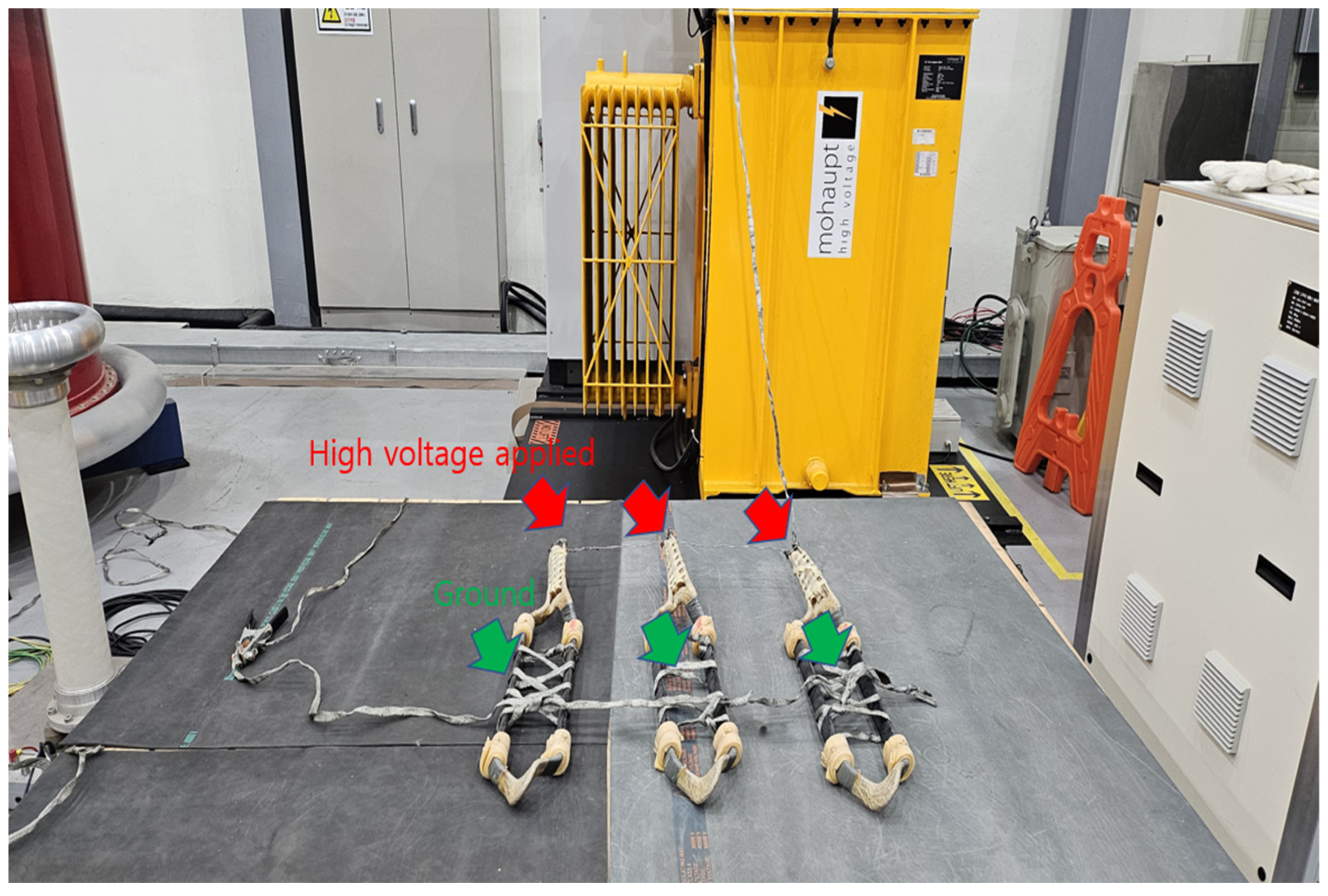
2.1. Testing Equipment

A variable-frequency dielectric strength tester (Figure 1), provided by the High Voltage Life Assessment Laboratory at the Korea Marine Equipment Research Institute, was utilized as the primary testing equipment in this study. The specialized equipment was specifically designed to evaluate the performance and durability of electrical insulation systems under high-voltage and variable-frequency conditions, making it highly suitable for assessing insulation degradation mechanisms in environments with varying frequencies. The tester can operate over a wide range of frequencies, ensuring that the insulation materials are exposed to realistic electrical stress conditions encountered in practical applications, particularly in marine power systems and other high-voltage electrical equipment. The equipment has a rated current of 1 A, which is suitable for testing large-scale insulation systems used in shipboard electrical networks, offshore power grids, and industrial applications. Furthermore, the system ensures stable voltage regulation and precise frequency control, enabling researchers to accurately simulate real-world operating conditions where insulation materials experience continuous electrical and thermal stresses. The reliability and accuracy of the test data generated by the equipment provide a solid foundation for evaluating the long-term performance of insulation systems under accelerated life testing conditions. Table 1 summarizes the technical specifications of the variable-frequency dielectric strength tester used in this study. The inverter-based variable-frequency dielectric strength tester used in this study employs pulse-width modulation (PWM) control to ensure precise frequency and voltage regulation. It is equipped with an output sine filter and partial discharge (PD) filter to minimize harmonic distortions and electrical noise, respectively, providing stable and reliable test conditions. The harmonic distortion level was maintained below 3%, which ensured that the insulation samples were subjected to realistic, high-quality electrical stress conditions similar to those encountered in practical marine power systems.

2.2. Testing Process

The experimental setup (Figure 2) was systematically designed to quantitatively analyze the correlation between failure time and frequency in insulation systems. The feasibility of reducing test durations could be evaluated by increasing frequency. The experimental framework provided a controlled testing environment, which ensured consistent and reliable data collection to support the development of accurate mathematical models for insulation degradation analysis. To enhance the statistical reliability of the results, repeated experiments were conducted at different frequency conditions, which ensured data reproducibility and validation. These repeated trials enabled the development of a comprehensive dataset. Moreover, it ensured that the observed trends were reflective of actual insulation degradation behaviors under high-frequency stress conditions, and the trends were not caused by random variations.
In this study, a 6.6 kV insulation system, specifically designed for marine electrical applications, was used as the test sample. The insulation system was fabricated using mica-based corona-resistant and semi-corona insulation materials, which are widely used in high-voltage marine power systems owing to their superior dielectric strength and resistance to electrical stress. Insulation layers were applied to the conductor using a precise taping process, ensuring uniform thickness and optimized dielectric performance. The mica-based corona-resistant insulation tape used in this study was manufactured by Von Roll (Samicatherm 366.55, Breitenbach, Switzerland). The insulation tape has a dielectric strength of 20 kV/mm and a thermal rating of Class F (155 °C). The epoxy resin utilized for vacuum pressure impregnation (VPI) was supplied by Huntsman (Araldite CY 225/HY 925, Hong Kong). The epoxy resin is characterized by excellent mechanical strength and resistance to thermal degradation. These specifications enabled the insulation system to withstand the high electrical and thermal stresses typically encountered in marine electrical applications. VPI was employed to fill the microscopic voids between the insulation layers with epoxy resin, which enhanced the durability of the insulation system. The VPI process played a crucial role in eliminating air pockets, thereby improving the mechanical integrity, electrical reliability, and overall insulation lifespan under high-voltage and high-frequency operating conditions. The entire fabrication process was meticulously controlled to ensure the structural stability and long-term durability of the insulation system. Structural stability and long-term durability are crucial in harsh marine environments where moisture, salt exposure, and variable frequency stresses can accelerate material degradation.
A total of 12 insulation samples were prepared using identical materials and manufacturing conditions to ensure consistency in testing and the accuracy of the data. The samples were divided into four testing groups, with three samples tested at each frequency condition (60, 300, 600, and 900 Hz). The samples were tested at progressively increasing frequencies to determine the extent to which higher frequencies accelerate insulation degradation and whether frequency-based accelerated life testing could be an efficient alternative to conventional long-term insulation evaluation methods. Each sample was subjected to high-voltage stress under its designated frequency until failure, and the obtained failure times were used to develop mathematical models that describe the relationship between the frequency and insulation system longevity. The multi-sample approach and repeated trials ensured data reliability and minimized variations, facilitating a robust statistical analysis.
The testing process was systematically structured to ensure precision and consistency in evaluating the performance of the insulation system under different frequency conditions. It entailed equipment initialization, frequency-based testing, and real-time data recording to enable a controlled assessment of insulation degradation trends.
The equipment was calibrated before testing, and the output voltage and frequency were precisely adjusted to match the designated conditions. The sine filter minimized harmonic distortions, and the PD filter reduced noise. It improved the accuracy of insulation degradation measurements. A coupling capacitor prevented errors in data acquisition by stabilizing high-voltage signals. The experiments were conducted at four frequencies, 60, 300, 600, and 900 Hz, and a constant voltage of 19.14 kV (2.9 times the rated voltage) was applied to maintain uniform electrical stress. The test frequencies (60, 300, 600, and 900 Hz) were selected to represent a range of operating conditions relevant to marine power systems. Specifically, 60 Hz corresponds to the standard electrical grid frequency used in marine and industrial applications, while 300 Hz and 600 Hz reflect medium-frequency propulsion drives commonly found in variable-speed motor applications. The highest test frequency, 900 Hz, represents high-frequency converter-driven systems, such as those used in modern power electronic converters and inverter-based propulsion systems. The selected frequencies encapsulate the insulation degradation trends across a wide spectrum of practical marine electrical environments. Three insulation samples were tested per frequency, each subjected to continuous high-voltage exposure until failure, with failure times recorded for analysis. Throughout testing, real-time data recording ensured that failure times, voltage stability, and partial discharge activity were tracked accurately, providing a quantitative basis for analyzing frequency-dependent insulation degradation. These results contribute to the development of predictive models and demonstrate the feasibility of frequency-based accelerated life testing for marine electrical insulation systems.
The collected data were used to calculate the average failure time and then analyzed based on the repeated experimental results to enhance reliability. Two mathematical models, namely, the power and exponential decay models, were used to explain the relationship between frequency and failure time. The power model analyzed the nonlinear trend in failure time reduction via a log–log transformation, and the exponential decay model was used to precisely describe the reduction in failure time under high-frequency conditions. The coefficient of determination ( R 2 ) was calculated to assess the suitability of the models, and the reliability of the models was validated by comparing their fit with actual data.
The R 2 value indicates the explanatory power of the regression model and measures the fit of the model with the data. The R 2 value is within the range 0–1, with values closer to 1 indicating that the model explains the data extremely well, whereas values closer to zero suggest a poor fit with the data, implying that the independent variable struggled to predict the dependent variable. The R 2 values were calculated as follows:
R 2 = 1 S S R S S T ,
where SSR (Sum of Squares for Regression) and SST (Total Sum of Squares) denote the sum of squares of residuals and the total sum of squares, respectively. SSR represents the sum of squared differences between data points and model predictions, measuring the variance explained by the model. A high SSR indicates that the model fits the data poorly. SST, on the other hand, denotes the sum of squared differences between the data points and the mean value, indicating the total variation in data.
This experimental design was structured to minimize data variability and enhance the reliability of the results through repeated testing under controlled conditions. Fluctuations in failure time were reduced by conducting multiple trials at each frequency level, thereby ensuring that the observed degradation trends were consistent and reproducible. The degradation mechanisms of the insulation systems were analyzed across a broad frequency range from 50 Hz to 1000 Hz, representing both standard operating conditions and high-frequency stress environments. This comprehensive approach enabled the assessment of how electrical and thermal stresses evolve as frequency increases, resulting in changes in the partial discharge activity, dielectric breakdown, and structural deterioration of the insulation system. By systematically varying the frequency and monitoring insulation performance, this study demonstrated the feasibility of frequency-based accelerated life testing as an alternative to conventional long-duration testing methods. This approach provided quantitative insights into the correlation between frequency and failure time. Moreover, it provides a structured methodology to determine the extent to which higher frequencies can accelerate insulation degradation and reduce testing durations.
The design ensures the reliability and accuracy of the test data and provides a more practical foundation for assessing the feasibility of frequency-based testing time reduction compared to those reported in previous studies. This approach offers a novel method for reducing the long test durations that are typically required to evaluate insulation systems. Moreover, the method is optimized to analyze the effects of frequency variations on insulation performance. The experimental and modeling results provide crucial baseline data for future designs and evaluations of insulation systems.
Insulation failure was determined based on specific criteria, involving the continuous monitoring of PD activity using a PD measurement system (Haefely, DDX-9121b, Basel, Switzerland) with a detection sensitivity threshold set at 10 pC. Failure was identified by a sudden and irreversible dielectric breakdown, indicated by a sharp decrease in insulation resistance (to nearly zero) accompanied by a rapid increase in PD intensity surpassing 1000 pC. Once these conditions were observed, the test was immediately terminated, and the failure time was recorded.

2.3. Calibration Procedure

To ensure the accuracy and reliability of the experimental measurements, all test equipment was calibrated before the experiments. The high-voltage supply was calibrated using a reference voltage measurement device (Fluke, 8508A, Everett, WA, USA) with an accuracy of ±0.01%. The PD detection system (Haefely, DDX-9121b) was calibrated using a standard calibration pulse generator with a known charge level of 50 pC, following IEC 60270 guidelines [24]. Additionally, the insulation resistance measurement system was verified using a standard high-impedance resistor to confirm its precision within a ±5% tolerance. These calibration steps were performed before each test sequence to ensure measurement consistency and accuracy.

3. Results

3.1. Test Results

The average failure times were calculated by testing three samples for each frequency condition. Table 2 summarizes the results and indicates that the average failure time decreased by 41%, 76%, and 94% at frequencies of 300, 600, and 900 Hz, respectively, compared to that at 60 Hz.

3.2. Power Model

The power model represents the relationship between frequency and failure time as a nonlinear function, which can be linearized using a log–log transformation. The power model utilized in this study is based on the inverse power law, which is commonly employed to describe aging phenomena in insulation materials. The model assumes that insulation degradation is driven by cumulative stress effects, where increased electrical and thermal stresses accelerate degradation nonlinearly. The inverse power law relationship has been widely validated in insulation degradation research, supporting its applicability in predicting failure time under varying stress conditions, as demonstrated previously [5,17].
The model implements the following equation:
T = a · f b ,
where T denotes the failure time (h), f denotes the frequency (Hz), a refers to the failure time at 1 Hz (constant), and b is an exponent that represents the rate of failure time reduction as the frequency increases (constant).
Following log transformation, the equation becomes linear as follows:
log 10 ( T ) = log 10 ( a ) + b · log 10 f .
Linear regression analysis was performed using log-transformed data, and the following power model was derived as
T = 104.34 · f 0.91 .
In Equation (4), 104.34 represents the estimated failure time at a frequency of 1 Hz (approximately 21,854 h), and −0.91 indicates the rate at which the failure time decreases as the frequency increases.
The fit of the model was evaluated, and the R 2 value for the log–log-transformed data was 0.99, which indicates an excellent fit. This result suggests that the power model is a good fit for explaining the trend in failure time reduction across the frequency range 60 to 900 Hz.

3.3. Exponential Decay Model

The exponential decay model assumes that the failure time decreases exponentially as the frequency increases. The model can be defined as
T = T 0 ·   e k · f ,
where T denotes the failure time (h); f denotes the frequency (Hz); T 0 denotes the failure time at the initial frequency, 0 Hz (constant); and k refers to the decay rate of the failure time as the frequency increases (constant). In the exponential decay model, T 0 represents the failure time at the theoretical initial frequency of 0 Hz, i.e., no frequency-induced stress is applied. The choice of 0 Hz enables T 0 to directly represent the maximum possible failure time under no electrical stress, providing a clear theoretical basis for modeling the exponential decrease in failure time as the frequency increases. Based on the experimental data, the exponential decay model was derived as
T = 454.85 · e 0.00263 · f .
In Equation (6), 454.85 corresponds to the estimated failure time at the initial frequency (0 Hz), and 0.00263 indicates the rate at which the failure time reduces as the frequency increases.
The exponential decay model exhibited a particularly good fit with the measured data in the high-frequency range (600–900 Hz) with an R 2 value of 0.98. This indicates that the model is consistent with the reduction in failure time under high-frequency conditions.

3.4. Model Fit for Test Results

The two models exhibited distinct strengths in explaining the correlation between the frequency and failure time (Figure 3). The power model explains the nonlinear trend in failure time reduction across the entire frequency range. It facilitated the analysis by leveraging the linear characteristics of the log-transformed data. By contrast, the exponential decay model reflected the sharp decrease in the failure time more precisely under high-frequency conditions, indicating a superior fit in the 600–900 Hz range.
Both the power and exponential decay models exhibited high levels of data fit, with R2 values of 0.99 and 0.98, respectively. These results demonstrate that the models can be useful tools for quantitatively analyzing the effects of frequency variations on the degradation of and failure time reduction in insulation systems.
These findings contribute to improving the efficiency of insulation system evaluation and highlight the potential to reduce the testing duration, thereby presenting a more practical foundation for applications in testing methodologies.

4. Discussion

4.1. Impact of Frequency on Insulation System Degradation

This study confirms that the failure time of an insulation system can be greatly reduced by increasing the frequency, validating the feasibility of frequency-based accelerated life testing for marine electrical applications. The experimental results show that the failure time decreased from 381.83 h at 60 Hz to 22.33 h at 900 Hz, a 94% reduction. This supports previous findings which show that higher frequencies intensify electrical and thermal stresses, accelerating degradation mechanisms, such as PD and molecular breakdown [5,7,8].
These findings are particularly relevant for marine power systems, where insulation materials need to withstand the variable frequencies caused by power supply fluctuations, propulsion drives, and high-voltage converters. By demonstrating that higher frequencies can drastically shorten testing durations, this study provides a more efficient alternative to traditional endurance testing, which is critical to optimize the reliability of insulation systems in harsh marine environments. The accelerated degradation observed at higher frequencies can be explained by the intensified electrical and thermal stresses that increase PD and molecular breakdown within the insulation material. Specifically, PD activity was observed to increase both in frequency and intensity as the testing frequency rose from 60 Hz to 900 Hz. At higher frequencies, enhanced electron mobility facilitates more frequent PD events, which in turn accelerate molecular breakdown by weakening the polymer chains within the insulation material. Additionally, the increased dielectric heating at elevated frequencies exacerbates these effects, resulting in more rapid degradation. These observations align with the theoretical insights presented by Dissado and Fothergill [4] and Lu et al. [5], thereby providing a detailed understanding of how PD and molecular breakdown mechanisms vary with frequency.
The frequency-based accelerated life testing method demonstrated in this study provides a significant time reduction compared to conventional IEEE 117-1974 and IEC 60034-18-32 insulation system evaluation standards [1,2]. This method can be effectively applied to assess the long-term reliability of insulation systems in marine propulsion systems, generators, transformers, and power conversion devices. In particular, for high-frequency inverter-based propulsion systems (e.g., variable-speed drives, PWM converter systems), the conventional low-frequency testing approach is often impractical because of power fluctuations. By implementing the accelerated testing method proposed in this study, insulation performance assessments in marine power systems can be conducted much more efficiently than with existing evaluation techniques.

4.2. Suitability and Limitations of Mathematical Models

In this study, two mathematical models, the power model and exponential decay model, were applied to describe the relationship between the frequency and failure time in insulation systems. Both models effectively captured the degradation trends observed in the experimental data, demonstrating their suitability to analyze frequency-based accelerated life testing. The power model exhibited excellent accuracy across the entire frequency range (60–900 Hz) and achieved a high coefficient of determination ( R 2   = 0.99). The model successfully described the nonlinear relationship between frequency and failure time, highlighting its potential to be used in long-term insulation performance assessments. Its ability to fit experimental data at lower frequencies (60–300 Hz) suggests that it can be applied to predict insulation failure under standard operating conditions. The exponential decay model showed greater accuracy in the high-frequency range (600–900 Hz), indicating its potential usefulness in evaluating insulation degradation in high-frequency marine power systems. The exponential decay model effectively captured the rapid decrease in failure time at elevated frequencies, suggesting that it can be a valuable tool for testing the reliability of insulation materials used in inverter-driven propulsion systems and variable-speed drives in shipboard applications. Although the current models effectively captured the frequency range studied (60–900 Hz), additional validation is required across a broader frequency spectrum. Future studies should include testing at lower frequencies (<50 Hz), which are commonly encountered in large marine generators, as well as at higher frequencies (>1 kHz), relevant to high-power marine electronics. An extended validation can enhance the robustness and practical applicability of the developed models under diverse, real-world marine operating conditions.
Notably, the high R 2 values obtained in this study are based on only four data points, potentially limiting their statistical significance. While our initial results are promising, statistical best practices recommend a minimum of 30 data points to draw robust conclusions. Therefore, further experiments incorporating more data points can fully validate the reliability and predictive accuracy of the models.

4.3. Performance Characteristics of Insulation System Design

Mica-based insulation materials combined with epoxy resin ensured the reliable performance of the system in evaluating the effects of frequency variations. The enhanced interlayer bonding strength realized via VPI played a critical role in improving the high-frequency tolerance of the insulation system. To further validate and generalize these findings, future studies should include comparative experiments with other insulation materials, such as polymeric or nanocomposite systems. Such additional validation will confirm the broader applicability of frequency-based accelerated testing methods and provide insights into the performance differences among various insulation materials under high-frequency stress conditions.

4.4. Applicability of Experimental Results

The study findings provide essential baseline data to evaluate the performance of insulation systems in practical application environments, such as marine equipment and high-voltage power systems. The proposed frequency-based accelerated testing method offers a practical alternative to conventional time-intensive evaluation methods. However, further research is required to apply these findings directly to real-world applications. For instance, further testing is required under marine environments with different temperature conditions, high humidity, and exposure to salt. Additionally, different insulation materials can be examined to enhance the applicability of these findings. Moreover, the frequency range needs to be expanded to incorporate long-term degradation mechanisms. Furthermore, test data need to be validated in industries beyond marine applications, such as aviation and railways. Importantly, this study utilized three samples per frequency condition, which aligns with standard practices in similar studies [5,7,8]. Existing research indicates that a minimum of three samples is often sufficient to obtain reliable initial insights into insulation system degradation under various frequency conditions. However, an increased number of samples would further enhance the robustness and generalizability of the findings. Additionally, the current analysis is based on only four frequency conditions, which can limit the statistical reliability of our conclusions. To address this limitation, further experiments covering intermediate frequencies will be conducted in future work. These additional experiments will provide more comprehensive data points, enhancing the reliability and accuracy of the mathematical models and strengthening the overall validity of the findings.
Moreover, marine power systems operate in environments exposed to salt, which can greatly influence insulation performance. Although the present study did not analyze this parameter, it is essential to consider salt exposure conditions in future research. Such studies can more accurately simulate actual marine conditions, further validating the practical applicability and reliability of the proposed frequency-based accelerated life testing method.
It is also important to acknowledge that the rated current used in this study (1 A) is lower than the typical operating currents found in large-scale marine applications. However, the primary objective of this study was to evaluate insulation degradation under controlled high-voltage and variable-frequency conditions, rather than to replicate full-load operational currents. Therefore, the selected test conditions remain valid for assessing insulation performance because insulation stress is primarily influenced by voltage and frequency rather than the magnitude of current. Nevertheless, this limitation should be considered when extrapolating the results to real-world marine environments, where higher operational currents may introduce additional thermal and electrical stresses.

5. Conclusions

This study experimentally analyzed the correlation between failure time and frequency in insulation systems, demonstrating the potential to drastically reduce test durations through frequency-based accelerated life testing, particularly in marine applications. The key findings are summarized as follows:
  • Failure time decreases as frequency increases: The test results confirmed a nonlinear reduction in failure time, with a 94% decrease from 381.83 h at 60 Hz to 22.33 h at 900 Hz, confirming the findings of previous studies on frequency-driven insulation degradation.
  • Potential to reduce testing durations: Compared to conventional IEEE and IEC standards that require 5000 h of testing at 60 Hz, this study showed that equivalent degradation could be observed within 22.33 h at 900 Hz, demonstrating a 99.6% reduction in test time.
  • Validation of mathematical models: The power model provided an excellent fit across all frequencies ( R 2   = 0.99), while the exponential decay model proved highly accurate in the high-frequency range (600–900 Hz), confirming its suitability for high-frequency testing applications.
  • Reliability of the insulation system design: The mica-based insulation system with epoxy resin showed strong durability under varying frequency conditions, ensuring stable and reproducible test results.
This study provides foundational data to improve the efficiency of insulation system evaluations and contribute to the enhancement in design and evaluation processes. The results have potential applications in high-voltage power systems used in ships, the aviation industry, railways, and other sectors.

Funding

This work was supported by the Ministry of Trade, Industry & Energy (MOTIE), Korea Planning & Evaluation Institute of Industrial Technology (KEIT), through Innovative Green Ship Technology Development (RS-2023-00252794).

Data Availability Statement

The data presented in this article are available upon request from the corresponding author.

Conflicts of Interest

The author declares no conflicts of interest.

References

  1. IEEE 117-1974; IEEE Standard Test Procedure for Evaluation of Systems of Insulating Materials for Random-Wound AC Electric Machinery. IEEE: Piscataway, NJ, USA, 1974; pp. 1–24. [CrossRef]
  2. IEC 60034-18-32; Rotating Electrical Machines—Part 18–32: Functional Evaluation of Insulation Systems (Type II)—Electrical Endurance Qualification Procedures for Form-Wound Windings. IEC: Geneva, Switzerland, 2022.
  3. IEC 60505; Evaluation and Qualification of Electrical Insulation Systems. IEC: Geneva, Switzerland, 2011.
  4. Dissado, L.A.; Fothergill, J.C. Electrical Degradation and Breakdown in Polymers; Peter Peregrinus Ltd.: London, UK, 1992. [Google Scholar]
  5. Lu, Y.; Knight, A.M.; Malik, O. Insulation degradation mechanism analysis under different applied voltages and frequencies. In Proceedings of the 2020 IEEE International Conference Electrical Insulation and Dielectric Phenomena (CEIDP), East Rutherford, NJ, USA, 18–30 October 2020; pp. 63–66. [Google Scholar] [CrossRef]
  6. Lee, S.; Yoon, S.; Kim, D.; Kim, M.; Park, K.H.; Lee, S.; Kim, D.; Kim, J. Accelerated Life Test of Eco-Friendly PP-TPE Insulating Material Using Frequency Acceleration. J. Electr. Eng. Technol. 2023, 18, 3773–3781. [Google Scholar] [CrossRef]
  7. Zhang, W.; Jiang, J.; Li, B.; Shen, Z.; Ma, G.; Zhang, C. Partial discharge features of insulation for power electronic transformers under time-temperature aging. CPSS Trans. Power Electron. Appl. 2023, 8, 363–371. [Google Scholar] [CrossRef]
  8. Liu, T.; Li, Q.; Dong, G.; Asif, M.; Huang, X.; Wang, Z. Multi-factor model for lifetime prediction of polymers used as insulation material in high frequency electrical equipment. Polym. Test. 2019, 73, 193–199. [Google Scholar] [CrossRef]
  9. Liang, B.; Lan, R.; Zang, Q.; Liu, Z.; Tian, L.; Wang, Z.; Li, G. Influence of thermal aging on dielectric properties of high voltage cable insulation layer. Coatings 2023, 13, 527. [Google Scholar] [CrossRef]
  10. Vocke, J.; Moser, A. Durability tests on solid insulation materials for medium frequency transformers in the frequency range from 1 kHz to 10 kHz. In VDE High Voltage Technology; 4. ETG-Symposium; VDE: Berlin, Germany, 2022; Volume 169, pp. 95–100. [Google Scholar]
  11. Zhang, B.; Ghassemi, M.; Zhang, Y. Insulation materials and systems for power electronics modules: A review identifying challenges and future research needs. Dielectr. Electr. Insul. 2021, 28, 290–302. [Google Scholar] [CrossRef]
  12. Phloymuk, N.; Pattanadech, N. The aging of the insulation system of large rotating machines in frequency domains. In Proceedings of the 2019 IEEE Conference on Electrical Insulation and Dielectric Phenomena (CEIDP), Richland, WA, USA, 20–23 October 2019; Volume 2019, pp. 1–4. [Google Scholar] [CrossRef]
  13. Farahani, M.; Gockenbach, E.; Borsi, H.; Schäfer, K.; Kaufhold, M. Behavior of machine insulation systems subjected to accelerated thermal aging test. IEEE Trans. Dielectr. Electr. Insul. 2010, 2010, 1364–1372. [Google Scholar] [CrossRef]
  14. Calo, E.; Álvarez, R.; Catalano, L.; del Valle, P.M. Dielectric frequency response of a MV stator coil: Effect of humidity and thermal ageing. In Proceedings of the IEEE International Conference Electrical Insulation and Dielectric Phenomena (CEIDP), Virtual, 18–30 October 2020; pp. 1–4. [Google Scholar] [CrossRef]
  15. Torres, J.; Homeier, K.; Stahl, L.; Werle, P. Influence of harmonic distortion on the breakdown voltage of a composite material for the use in dry type transformers. In Proceedings of the IEEE Conference on Electrical Insulation and Dielectric Phenomena (CEIDP) 2024, Auburn, AL, USA, 6–9 October 2024; Volume 2024, pp. 1–6. [Google Scholar] [CrossRef]
  16. Zidane, O.; Haller, R.; Trnka, P.; Bärnklau, H. Insulation for rotating machines Type II under different electrical stress conditions. In Proceedings of the IEEE International Conference Electrical Insulation and Dielectric Phenomena, East Rutherford, NJ, USA, 15–19 October 2023; Volume 2023, pp. 1–6. [Google Scholar] [CrossRef]
  17. Kang, D.S.; Hwang, D.H.; Nam, T.K.; Kim, Y.J. Novel sensor for locating partial discharges in high-voltage rotating machines. IEEE Trans. Energy Convers. 2007, 22, 576–583. [Google Scholar] [CrossRef]
  18. Nair, R.P.; Vishwanath, S.B. The applicability of very low frequency diagnostic testing in the evaluation of thermally aged stator coil. IEEE Trans. Dielect. Electr. Insul. 2023, 30, 1223–1230. [Google Scholar] [CrossRef]
  19. Sumereder, C.; Woschitz, R.; Muhr, M. Condition evaluation of generator bars. In Proceedings of the 2015 IEEE 10th International Symposium on Diagnostics for Electrical Machines, Power Electronics and Drives (SDEMPED), Guarda, Portugal, 1–4 September 2015; pp. 1–4. [Google Scholar] [CrossRef]
  20. Bhumiwat, S.A. On-site non-destructive dielectric response diagnosis of rotating machines. IEEE Trans. Dielect. Electr. Insul. 2010, 17, 1453–1460. [Google Scholar] [CrossRef]
  21. Soltani, R.; David, E.; Lamarre, L. Impact of humidity on dielectric response of rotating machines insulation system. IEEE Trans. Dielect. Electr. Insul. 2010, 17, 1479–1488. [Google Scholar] [CrossRef]
  22. Saha, T.K.; Purkait, P. Understanding the impacts of moisture and thermal ageing on transformer’s insulation by dielectric response and molecular weight measurements. IEEE Trans. Dielect. Electr. Insul. 2008, 15, 568–582. [Google Scholar] [CrossRef]
  23. Wang, Z.; Jia, Z.D.; Fang, M.H.; Li, Y.S.; Guan, Z.C. Moisture absorption, desorption, and moisture-induced electrical performances of high-temperature vulcanized silicone rubber. IEEE Trans. Dielect. Electr. Insul. 2016, 23, 410–417. [Google Scholar] [CrossRef]
  24. IEC 60270; High-Voltage Test Techniques—Partial Discharge Measurements. IEC: Geneva, Switzerland, 2000.
Figure 1. Variable-frequency dielectric strength tester.
Jmse 13 00500 g001
Figure 2. Experimental setup.
Jmse 13 00500 g002
Figure 3. Frequency and failure times compared to power and exponential decay models relative to measured data.
Jmse 13 00500 g003
Table 1. The specifications of the variable-frequency dielectric strength tester.
ItemDetails
ManufacturerMohaupt
Country of manufacturerAustria
Capacity50 kVA
Maximum output voltage50 kV
Frequency range50–1000 Hz
Rated current1 A
Table 2. Average breakdown time for each specimen.
Frequency
(Hz)
Breakdown Time per Specimen (h)Average Breakdown Time (h)
60 60-1560381.83
60-2290
60-3295.5
300 300-1213.5224.83
300-2247
300-3214
600 600-113990.33
600-214
600-3118
900 900-11622.33
900-244
900-37
Disclaimer/Publisher’s Note: The statements, opinions and data contained in all publications are solely those of the individual author(s) and contributor(s) and not of MDPI and/or the editor(s). MDPI and/or the editor(s) disclaim responsibility for any injury to people or property resulting from any ideas, methods, instructions or products referred to in the content.

