Article

Collision Avoidance Pattern with Collective Wisdom: Ship Action Decision-Making Azimuth Map Construction Based on COLREGs

1
School of Navigation, Wuhan University of Technology, Wuhan 430063, China
2
Hubei Key Laboratory of Inland Shipping Technology, Wuhan University of Technology, Wuhan 430063, China
3
Shanghai International Shipping Institute, Shanghai Maritime University, Shanghai 201306, China
*
Author to whom correspondence should be addressed.
J. Mar. Sci. Eng. 2025, 13(12), 2240; https://doi.org/10.3390/jmse13122240
Submission received: 2 November 2025 / Revised: 19 November 2025 / Accepted: 20 November 2025 / Published: 24 November 2025
(This article belongs to the Special Issue Maritime Security and Risk Assessments—2nd Edition)

Abstract

Ship collision avoidance decision-making is a core determinant of navigational safety, and its effectiveness directly governs a ship’s ability to operate safely in a complex environment. Although successive editions of the COLREGs have provided a relatively systematic qualitative description of the principal encounter state and corresponding handling principles, they still lack a quantitative specification of collision avoidance actions. As a result, ship officers must rely heavily on experiential judgment for state recognition and decision-making in real operations, which in turn increases the likelihood of human error-induced failures in avoidance. To address this problem, this study constructs a COLREG-compliant collision avoidance decision azimuth map derived from the collective wisdom of ship officers. Specifically, a two-stage mining process tailored to large-scale AIS data is designed: in the first stage, ship–ship encounter cases are extracted from the full dataset, and, in the second stage, collision avoidance actions are mined from these encounter cases. Subsequently, a decision tree classification model is employed to partition the latent relationships between the relative motion features of two ships and their collision avoidance actions under different encounter scenarios, thereby constructing a data-driven ship collision avoidance decision azimuth map. Finally, taking the eastern coastal waters of China as a case study, the constructed ship collision avoidance action azimuth map is shown to provide scenario-specific guidance for two-ship encounters, offer an objective basis for the quantitative enrichment of COLREGs, and supply a methodological reference for future autonomous ship collision avoidance systems.

1. Introduction

As an integral component of maritime activities, waterborne transportation plays a pivotal role in linking international trade and driving the growth of the ocean economy [1]. However, this growth has been accompanied by an increasingly prominent concern over maritime traffic safety. In particular, the scientific analysis and improvement of ship collision avoidance behavior and decision-making have become an urgent requirement for ensuring safe waterborne transport [2].
In recent years, many critical waterways have experienced a marked increase in ship traffic activity and density. This has accelerated the variability of navigational environments, heightened situational uncertainty, and rendered encounter scenarios more complex, thereby making situation awareness and collision avoidance decision-making increasingly challenging for ship officers operating under high workload conditions. Although modern ships are equipped with advanced systems, such as the Automatic Identification System (AIS), Automatic Radar Plotting Aids (ARPAs), and Integrated Navigation Systems (INSs), to enhance navigational safety [3], accident investigations still reveal that more than 80% of maritime traffic incidents are linked to human-related factors [4,5]. This indicates that, prior to the full advent of autonomous ships, collision avoidance decision-making remains the most risk-prone segment of conventional navigation. Although the current COLREGs provide a systematic normative basis for most encounter states and corresponding actions, they are predominantly qualitative and offer little quantitative guidance on specific avoidance maneuvers [6]. Consequently, practical collision avoidance decisions still rely heavily on crew experience and individual maneuvering preferences. Moreover, the rapid emergence of new technologies and related industries has disrupted traditional seafarer training pathways and accelerated the loss of experience-based personnel [7], further amplifying human-induced uncertainty.
Therefore, at the early stage of intelligent ship development, providing a quantifiable and executable refinement of existing rules becomes an effective pathway to enhancing navigational safety. With the upgrading of onboard systems, the wide adoption of AIS has offered a simpler and more efficient means of acquiring ship information [8,9]. At the same time, under the constraints of the COLREGs, elements such as mariners’ maneuvering preferences and actual avoidance actions—previously difficult to capture by other means—can now be observed in AIS trajectories. This makes it feasible to adopt a data-driven approach to retrospectively mine latent collision avoidance patterns from real-world cases and, on this basis, to concretize and operationalize the existing rules.
To this end, this study constructs a ship collision avoidance decision azimuth map that integrates AIS data with the COLREGs. By mining large-scale AIS trajectories to extract historical collision avoidance cases and identifying recurrent, generalizable action patterns, the proposed approach aims to provide guidance for ships operating in analogous encounter scenarios. The main contributions are as follows: (1) a two-stage mining procedure is developed to infer collision avoidance behaviors from massive AIS data, in which ship–ship encounter cases are first identified and then the corresponding avoidance actions are reverse-engineered; (2) based on a decision tree algorithm, the relationships between encounter relative bearing, distance, relative motion features, and the adopted avoidance actions are partitioned for three canonical situations—head-on, crossing, and overtaking—thereby constructing a ship collision avoidance decision azimuth map. This study reveals how ships typically approach one another and how they pass each other during avoidance, enabling objective decision support for present-day collision avoidance in similar scenarios and providing a theoretical reference for future maritime autonomous surface ship (MASS) collision avoidance systems.
The remainder of this paper is organized as follows. Section 2 reviews recent advances in ship encounter state classification and ship behavior mining. Section 3 presents the overall research framework and methodology, including data preprocessing, encounter case extraction, collision avoidance behavior mining, and the decision tree model. Section 4 reports and analyzes the results, focusing on the mined collision avoidance patterns, the behavioral partitions for head-on, crossing, and overtaking encounters, and the construction of the collision avoidance decision azimuth map. Section 5 discusses the implications of the findings. Section 6 concludes the paper.

2. Literature Review

2.1. Related Research on Ship Encounter Scenarios

In ship collision avoidance, determining the encounter situation based on the azimuth of the approaching ship is a prerequisite for taking appropriate maneuvers. Under the COLREGs, encounter situations are first classified as follows: 354–6° is defined as a head-on situation, 6–112.5° and 247.5–354° are defined as crossing situations, and 112.5–247.5° is defined as an overtaking situation. On this basis, many scholars [10,11] in the maritime/navigation domain have refined and supplemented encounter recognition models using the COLREGs as the fundamental reference. Building on 236 expert questionnaires, Zheng et al. [12] synthesized the responses and proposed a ship bearing sector division chart, in which the encounter sectors are divided into 5–67.5°, 112.5–210°, and 247.5–355°. Wu et al. [13] developed a three-layer intelligent collision avoidance architecture for unmanned surface vessels (USVs) and, within this framework, proposed a COLREG-constrained, partition-based encounter recognition and decision mechanism. By computing relative motion parameters, constructing a layered collision risk model (safe zone–prediction zone–emergency zone), and refining the “head-on–crossing–overtaking” rule reasoning according to relative bearing, the USV is enabled to generate executable autonomous avoidance maneuvers in multi-ship environments, and the effectiveness of the scheme was verified through simulations. Kim et al. [14] proposed an intelligent ship collision avoidance support system (HiCASS), which, on the basis of COLREGs, partitions the target ship’s relative bearing into several sectors—22.5°, 90°, 112.5°, 150°, 210°, 247.5°, 270°, and 337.5°—to clarify specific responsibilities in crossing, head-on, and overtaking situations. By fusing AIS and ARPA data, the system performs real-time collision risk assessment and, when the risk exceeds 60%, outputs COLREG-compliant rerouting suggestions together with rudder and heading control commands. Perera et al. [15] addressed the “course-to-port/course-to-starboard” contradictions that often arise near sector boundaries in conventional COLREG-based fuzzy decision-making by subdividing the own ship’s collision space into ten regions (I–X) and assigning specific rudder and engine commands to each region. To ensure smooth transitions between adjacent regions, they further introduced intermediate transition bands. The core idea is a fine-grained sectorization of the azimuth: the region boundary angles are set sequentially at 5°, 85°, 95°, 175°, 185°, 211°, 265°, 275°, 329°, and 355°, enabling the system to provide continuous, locally optimal collision avoidance actions for overtaking, head-on, and crossing encounters. Gao M et al. [16], using AIS data, reconstructed the relative motion processes of two ships under different encounter scenarios and, in conjunction with the arc range requirements of navigation lights in the COLREGs, employed a support vector machine to classify the actual avoidance maneuvers between the own ship and a target ship. On this basis, they developed a corresponding encounter bearing partition chart, in which the sector boundaries were set at 2°, 5°, 44°, 107°, 203°, 257°, 306°, and 355°.
In summary, a substantial body of research has built upon the classical COLREG-based partitioning of head-on, crossing, and overtaking situations, and—through the incorporation of expert knowledge, real navigation data, and intelligent ship control requirements—has progressively refined and fuzzified the encounter azimuth boundaries. This evolution spans from early discrete multi-scenario classifications grounded in questionnaires and rule cognition to partitioning schemes with fuzzy transition bands, and further to AIS-driven, machine learning-based studies that derive near-optimal decision boundaries, thereby accomplishing a gradual shift from rule-based to data-driven encounter recognition and collision avoidance decision-making.

2.2. Related Research on Ship Behavior Mining

Ship behavior mining is typically based on AIS data and, through processes such as data cleansing and feature extraction, seeks to uncover behavioral patterns of ships to reveal latent regularities in navigation, encounter, and collision avoidance processes. This, in turn, provides key technical support for autonomous ship navigation, maritime traffic management, and collision risk early warning.
Wang et al. [17] reviewed the impact of ship behavior detection on maritime traffic safety and surveyed existing models from the perspectives of data, algorithms, and computational capacity, outlining their practical applications in intelligent navigation. These studies collectively indicate that rapidly and accurately extracting ship collision avoidance trajectories is critical for determining the appropriate avoidance timing, deepening the understanding of ship maneuvering behavior and enhancing the reliability of intelligent and digitalized navigation systems [18,19], which have thus become a key research focus in data-driven maritime studies in recent years.
Zhou et al. [20] proposed using the moment of minimum distance between two ships as the critical point of an encounter and, based on a sliding-window algorithm, identified ship behaviors by detecting variations in heading and speed. The encounter process was further segmented into four stages—pre-decision, pre-critical, post-critical, and post-passing—according to key maneuvering feature points, and ship behaviors were recognized through the analysis of the composite motion states of the two ships. Rong et al. [21] proposed a data-mining approach for maritime route feature extraction and anomaly detection, in which course-change events are identified via trajectory compression, and routes with different characteristics are clustered using the density-based spatial clustering of applications with noise (DBSCAN) algorithm. Cai et al. [22] proposed a generic meta-trajectory-based variable sliding-window (Meta-VSW) method. In this approach, ship data are first encoded into minimal behavioral units containing four-dimensional attributes such as position and speed; then, through a dual-pointer variable sliding-window algorithm, five typical behaviors—berthing, mooring, unberthing, sailing, and temporary anchoring—are efficiently identified, thereby providing effective support for behavior mining and performance analysis across different ship types.
Chen et al. [23] proposed a CNN-SMMC method in which AIS trajectory sequences are first encoded into multi-channel images containing speed and course-change patterns via the SMIGL algorithm, and then a convolutional neural network is used to discriminate three motion states—“static,” “underway,” and “collision avoidance.” A systematic comparison with baseline models such as KNN, SVM, and decision trees showed that this method significantly outperforms traditional hand-crafted feature approaches across multiple evaluation metrics. Building on behavior recognition, Chen et al. [24] moved toward behavior prediction and developed a ship trajectory forecasting framework based on a bidirectional long short-term memory (Bi-LSTM) network; by leveraging a dual-layer architecture to learn bidirectional temporal dependencies from both past and future trends and by feeding AIS latitude–longitude and speed sequences into the model, they realized real-time position warnings for single-ship and multi-ship encounters in highly congested inland waterways. Focusing on practical collision avoidance scenarios, Gao et al. [25] constructed a real-time ship behavior prediction model using a bidirectional LSTM recurrent neural network (Bi-LSTM-RNN), which preserves both forward and backward temporal features and, through the use of forget gates, mitigates the impact of noise, thereby achieving the high-accuracy short-term prediction of target ship course and speed using actual AIS data from Tianjin Port.
Wang et al. [26] combined KNN-based clustering and validation to detect different ship behaviors by integrating ship trajectories, vessel attributes, and motion patterns, and introduced a single anomaly behavior factor as the only parameter in the detection process; the model’s performance was evaluated on simulated datasets and shown to be applicable to real AIS data. To address the low efficiency of ship anomaly detection, Zhang et al. [27] proposed an AIS-driven anomaly behavior detection method that treats clustered AIS trajectory categories as the normal trajectory model and employs deep learning as the anomaly detector. Aiming to further improve behavior recognition accuracy and traffic management efficiency, Ma et al. [28] developed a ship behavior recognition method based on the SSA-XGBoost algorithm. By extracting five-dimensional behavioral features—including ship bearing, course variation, and speed variation—the method characterizes the distribution of ship behaviors in different waters and builds a high-accuracy recognition model, achieving 97.28% accuracy and outperforming traditional algorithms such as random forests and GBDT.
In trajectory simplification, traffic behavior extraction, and turning point detection, the most widely used approach is to derive trajectory features through trajectory compression [29,30]. Most compression-based methods identify behavioral changes by retaining key points along a ship’s track. As a classical algorithm in this field, the Douglas–Peucker (DP) algorithm has been applied to a variety of maritime trajectory-processing tasks. Jiang et al. [31] further improved ship trajectory compression quality based on the FP-TSDP algorithm to better capture critical dynamic behaviors such as deceleration, course alteration, and entering or leaving restricted areas. Nevertheless, ship behavior recognition methods that rely on trajectory compression are generally sensitive to threshold settings, and thus are prone to various errors in real-world applications.

3. Methodology

To extract collision avoidance cases from large volumes of ship trajectory data, this section presents the research methodology, as illustrated in Figure 1. To ensure data reliability and the soundness of the conclusions, the framework consists of four components: AIS data preprocessing, ship encounter state identification, ship collision avoidance behavior mining, and decision tree-based avoidance behavior partitioning.

3.1. AIS Data Preprocessing

Ship AIS data refer to the static and dynamic information collected and transmitted by the Automatic Identification System (AIS) installed on ships [32]. However, due to equipment limitations and external interferences, AIS transmissions may suffer from signal distortion, communication interruptions, or missing records, which can introduce anomalies and thus affect subsequent analysis and interpretation. To ensure the accuracy of ship collision avoidance behavior mining, the AIS data must first be cleaned. In this study, the following rules are applied: (1) records with longitude or latitude outside the target study area are removed; (2) records with speed over ground (SOG) outside the range of 3–40 kn are removed; (3) records with course over ground (COG) outside 0–360° are removed; and (4) records outside the designated observation period are removed. In addition, for unavoidable noise points, Qu et al. (2011) [33] proposed a trajectory-cleaning procedure to correct AIS data and update abnormal records. The method is grounded in Newtonian principles and the notion that average speed equals voyage distance divided by sailing time; using position logs together with the vessel’s acceleration/deceleration capability, it judges whether the recorded speed is reasonable and retroactively corrects positions accordingly. In this study, we adopt this procedure to further process and update the trajectories.
Moreover, because AIS messages are broadcast at intervals of roughly 3–20 s and ship motion states may change during sailing, the time stamps of AIS updates do not always align with the ship’s actual kinematic state. To extract collision avoidance cases more accurately, the trajectories must therefore be resampled to a unified time step. Considering that the study area consists of open waters—where ships generally maintain course and speed and are subject to fewer disturbances than in constrained waterways, resulting in relatively clean trajectories—this study applies cubic spline interpolation with a 10 s interval to temporally synchronize the ship tracks [34].

3.2. Ship Encounter State Identification

One of the principal causes of uncoordinated collision avoidance actions between ships is the inconsistency in encounter situation perception among watch officers. Accordingly, this study begins from the COLREGs and identifies ship–ship encounter trajectory pairs from large-scale AIS data by determining the encounter state between two ships under different scenarios, while ensuring both the accuracy and the uniqueness of the recognized results.

3.2.1. Encounter Situation Classification

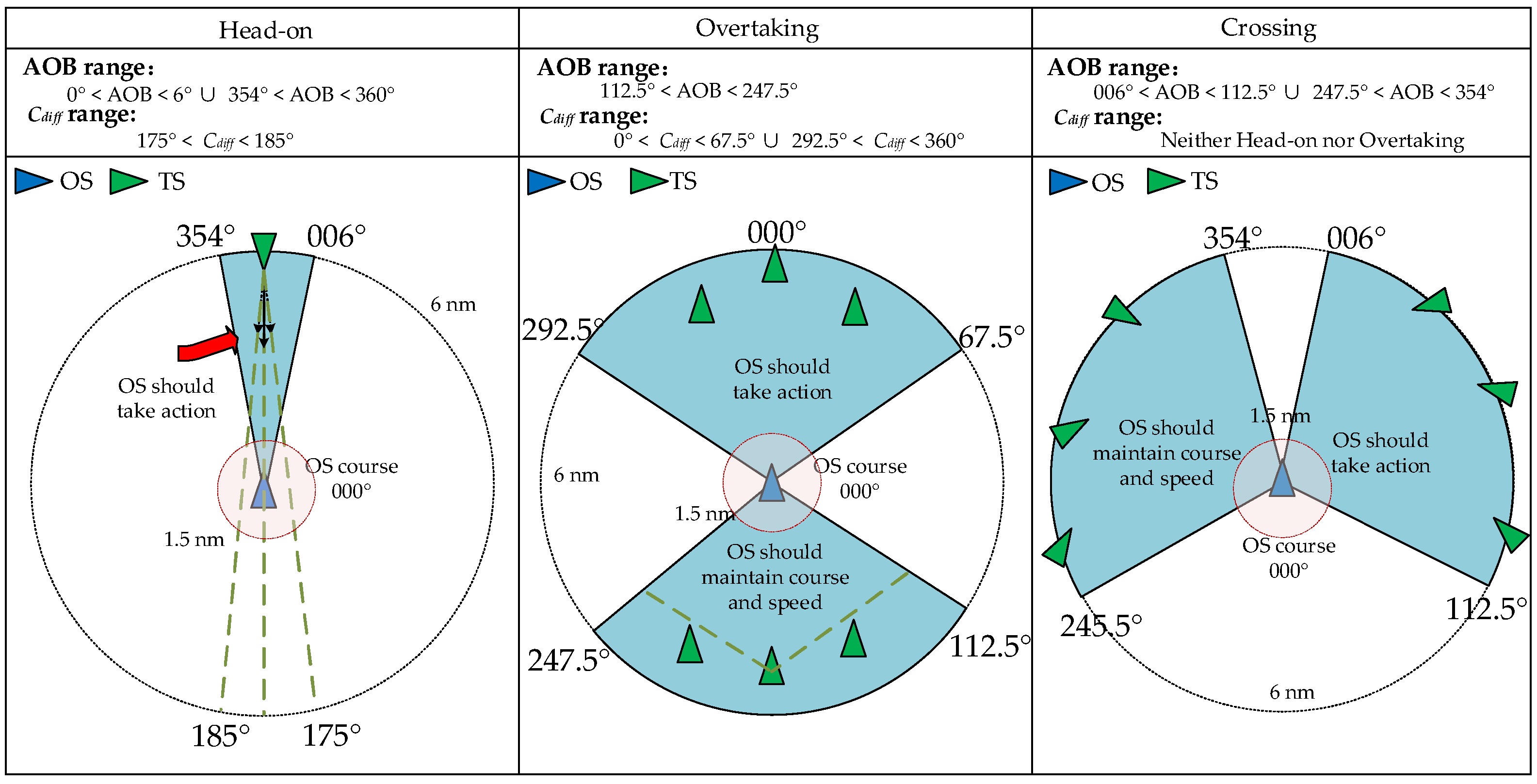
For encounter classification, rules 13–15 of the COLREGs divide ship encounters under conditions of mutual visibility into three canonical situations—head-on, crossing, and overtaking—and provide qualitative guidance for each. However, the COLREGs do not specify explicit quantitative thresholds for these situations. Consequently, many scholars have refined these three encounter types based on the COLREGs to compensate for this lack of quantitative criteria [35]. Building on this line of research, this study adopts the relative bearing (AOB) and the course difference (Cdiff) between two ships as the key indicators to categorize encounter situations. The classification parameters are summarized in Table 1.
For the head-on situation, the classification is made jointly by the relative bearing and the course difference between the two ships. When the target ship appears within ±6° of the ship’s bow (approximately half a compass point [36,37]), that is, when the bearing is within 000–006° or 354–360°, and the two ships are proceeding on nearly reciprocal courses, the situation is defined as head-on. Accordingly, a head-on situation is specified as a bearing = ±6° and course difference within the range of 175–185°.
For the overtaking situation, a necessary condition is that the own ship, acting as the overtaking vessel, proceeds at a higher speed to close on the target ship. In this case, the target ship should be located within a small forward sector of the own ship and should keep a broadly similar course. Thus, the overtaking situation is defined as a relative bearing within 0–67.5° or 292.5–360° and course difference within 0–67.5° or 292.5–360°.
For the crossing situation, in unrestricted waters, crossing is the most common two-ship encounter, where the two courses intersect and a collision risk exists. When the own ship is the give-way vessel, the target ship is expected to appear on the starboard side, and therefore the relative bearing for crossing encounters is set to 6–112.5°.

3.2.2. Spatiotemporal Modeling of Collision Risk

In navigational practice, ship officers initiate collision avoidance maneuvers only after recognizing that a risk of collision exists with the target ship. In open waters, encounters are typically detected at about 6–8 nautical miles (approximately the visibility range of the masthead light), which is regarded as the free-maneuvering stage and marks the beginning of the collision avoidance process [34,38]. Whether an avoidance action should be taken is usually evaluated by the combined indicators of Distance to the Closest Point of Approach (cpa) and Time to the Closest Point of Approach (tcpa). Although this joint criterion still has several known limitations, it remains one of the most practical and widely used approaches at present [39].
To capture as many collision avoidance actions as possible for ship pairs whose encounters occur within 8 nautical miles, and at the same time to reduce the disturbance caused by cases in which no avoidance action was actually taken, this study adopts the widely used circular ship domain and sets its radius to 1.5 nautical miles [40]. On this basis, a spatiotemporal collision risk model is established, as shown in Equation (1).
min ( c p a ) 1.5   nm t c p a > 0
By combining the encounter situation classification with the spatiotemporal collision risk model, a ship encounter state identification model can be obtained, as illustrated in Figure 2.

3.3. Ship Collision Avoidance Case Extraction

This section focuses on the two-stage process for extracting ship collision avoidance behaviors, which consists of a ship encounter case mining procedure and a subsequent avoidance behavior extraction procedure, as illustrated in Figure 3.

3.3.1. Ship Encounter Case Mining Procedure

Based on the ship encounter state identification model, all single-ship trajectory records within each spatiotemporal unit are traversed by Maritime Mobile Service Identity (MMSI), and encounter states between ships are identified through a forward rolling of time stamps. In this way, encounter cases are mined in which the target ship is likely to intrude into the collision domain (1.5 nm) of the own ship. Accordingly, a dedicated procedure is designed to extract encounter cases from massive AIS data, as shown in Figure 3.
First, the historical ship trajectory database is partitioned into time intervals. The initial interval is set to 1 h, and a two-pointer scheme is used to mark the start and end of each interval. The pointers roll forward by 40 min at each step, while retaining 20 min of data from the previous window. This design maintains continuity between adjacent intervals and improves the reliability of mining ship–ship encounter trajectories.
Next, as shown in Algorithm 1, encounter cases within the current time interval are mined. The input is the AIS trajectory database D S = { Traj 1 , Traj 2 , , Traj n } , where each trajectory Traj i = { MMSI i , l o n i , l a t i , s o g i , c o g i , t i } is a six-tuple consisting of ship identifier, longitude, latitude, speed over ground, course over ground, and timestamp. For every ship pair within the interval, the relative motion parameters are computed, including combined speed ( V R ), direction of relative motion ( r ), distance ( S ), relative bearing ( A O B ), course difference ( C d i f f ), distance to closest point of approach ( c p a ), and time to closest point of approach ( t c p a ); all of these can be obtained following the method of Gao et al. [16]. These parameters are then fed into the ship encounter state identification model to identify encounter situations that contain potential collision risk. For each identified pair, the corresponding encounter type is determined, and a label is assigned. The output is the encounter case database E D S = { Traj 1 e , Traj 2 e , , Traj n e } , where Traj i e = { c o g i , r i , A O B i , S i , c a s e I D i , s i t u a t i o n i } ; here, c a s e I D denotes the unique identifier of the encounter case and s i t u a t i o n denotes the encounter category. The detailed mining procedure is as follows.
Algorithm 1. Stage one: ship encounter case mining.
Input: DS = {Traj1, Traj2, …, Trajn}, Traji = (MMSIi, loni, lati, sogi, cogi, ti)
Output: EDS = {Traj1e, Traj2e, …, Trajne}, Trajie = {cogi, ri, AOBi, Si, caseIDi, situationi, ti}
Initialize: EDS = ∅; caseID = 0
1.for i in DS:
2. get Traji and sorted by ti
3. for u in DS:
4.  get Traju and sorted by tu
5.  if not Traji.MMSI == Traju.MMSI:
6.    Calculate VR, r, S, AOB, Cdiff, cpa, tcpa
7.    if S < 8 nmile:
8.      if cpa < 1.5 nm and tcpa > 0:
9.       if (0° ≤ AOB ≤ 6° or 354° ≤ AOB ≤ 360°) and 175° ≤ Cdiff ≤ 185°:
10.           situation = “Head-on”
11.        elif (112.5° ≤ AOB ≤ 247.5°)
           and (0° ≤ Cdiff ≤ 67.5° or 292.5° ≤ Cdiff ≤ 360°):
12.           situation = “Overtaking”
13.        elif (6° ≤ AOB ≤ 112.5° or 247.5° ≤ AOB ≤ 354°)
           and not (head-on/overtaking):
14.           situation = “Crossing”
15.        else end
16.caseID + = 1
17.Trajie = {cogi, ri, AOBi, Si, caseIDi, situationi}
18.EDS = {Traj1e, Traj2e, …, Trajne}
19.Output EDS

3.3.2. Ship Collision Avoidance Extraction

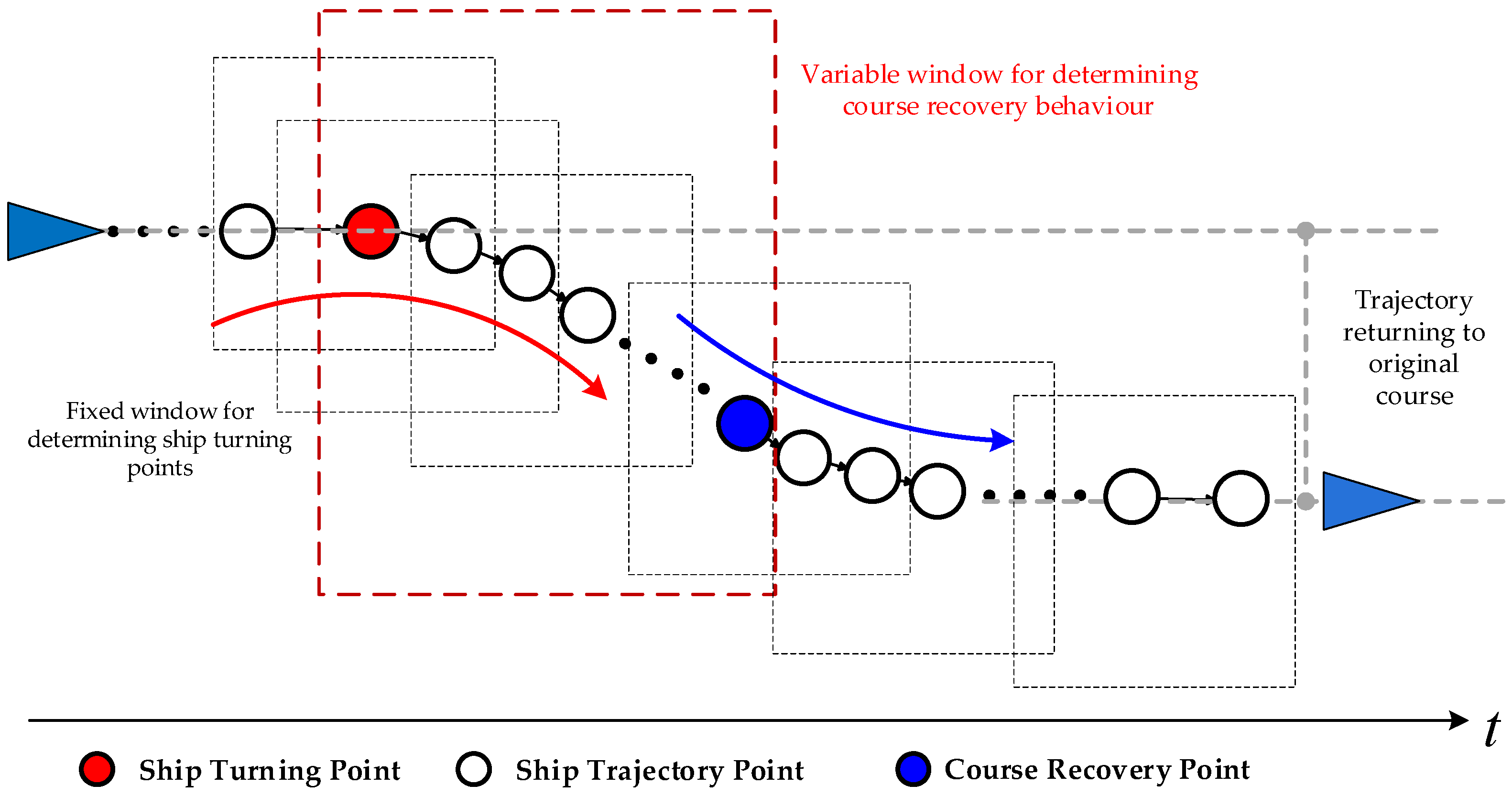
To accurately determine both the timing and the pattern of ship collision avoidance actions, this study further extracts avoidance behaviors from the trajectories contained in the identified encounter cases. In ship behavior mining, the sliding-window algorithm is commonly employed to detect course alteration actions [41]. Accordingly, with due consideration of the characteristics of collision avoidance actions and practical navigation procedures, this study uses a sliding-window-based method to detect turning points associated with avoidance and to mine the corresponding collision avoidance patterns.
The mining logic of this method is illustrated in Figure 4. For each trajectory, the algorithm constrains it with a combination of a fixed sliding window and a variable sliding window. As the windows move along the time series, the algorithm examines the correlation between successive course changes within each window. The fixed-length window is used to mark turning points, while the variable-length window is used to determine whether a given course alteration is driven by collision risk. By combining these two windows, the algorithm identifies both the collision avoidance action points and the corresponding maneuvering patterns.
As shown in Algorithm 2, the algorithm takes the encounter case database EDS as input and explores the ship’s course-change process through sliding windows. To prevent minor course fluctuations caused by environmental disturbances such as wind, waves, and current from being misidentified as turning actions, a course-change threshold Ths (this threshold indicates the number of consecutive course changes in the same direction; if the number of consecutive course changes during the sliding-window process exceeds Ths, the sequence is considered a deliberate turn by the ship officer) is introduced to filter out small deviations and ensure accurate action point detection. Considering the continuity of course alterations in open waters and in line with previous studies [42], Ths is set to 6. At the same time, a variable-length window is used to track whether the ship’s course recovers to its original tendency after the maneuver, to determine whether the course alteration was actually triggered by collision risk. If the maneuver is identified as a collision avoidance action, the algorithm outputs the avoidance action dataset eps = {ep1, ep2, …, epn}, where each record epi = {caseID, situation, S, AOB, r, action). Otherwise, the corresponding case is discarded. The detailed procedure is as follows.
Algorithm 2. Stage two: collision avoidance behavior extraction.
Input: EDS = {Traj1e, Traj2e, …, Trajne}, Trajie = {cogi, ri, AOBi, Si, caseIDi, situationi, ti}
Output: eps = {ep1, ep2, …, epn}, epi = {caseID, situation, S, AOB, r, action}
Initialize:  L c : fixed window size = 8, s: sliding step = 1, eps = None, Ths = 6
1. for i in EDS:
2. get Trajie and sort by ti
3. dir = 0; cnt = 0; idx_turn = None
4. for k in range (1, len(cog)):
5.  dC = cog[k] − cog[k−1]
6.  if dC > 0: cur_dir = +1
7.   elif dC < 0: cur_dir = −1
8.   else: cur_dir = 0 # no change
9.   if cur_dir ! = 0:
10.     if dir == 0:
11.      dir = cur_dir; cnt = 1
12.    elif cur_dir == dir: cnt + = 1
13.    else: dir = cur_dir; cnt = 1
14.    if cnt >= Ths and idx_turn is None:
15.      idx_turn = k − Ths
16.      get Traj eidx_turn
17. if idx_turn is None: continue
18. CL_min = min(cog [0:idx_turn + 1]); CL_max = max(cog [0:idx_turn + 1])
19. for m in range(idx_turn, len(cog)):
20.  if CL_min <= cog[m] <= CL_max:
21.   if cog[idx_turn + Ths] > cog[idx_turn]: action = “Starboard”
22.   elif cog[idx_turn + Ths] < cog[idx_turn]: action = “Port”
23.   else: action = None
24. break
25. append Traj eidx_turn.(caseIDidx_turn, situationidx_turn, Sidx_turn, AOBidx_turn, ridx_turn)
       and action to epi
26.eps = {ep1, ep2, …, epn}
27.Output eps

3.4. Encounter Scenarios Standardization

In open waters, collision avoidance behaviors mined from real cases often exhibit non-uniform encounter scenarios because there is no fixed environmental constraint. Encounters obtained under different azimuths and course differences may, in essence, correspond to the same geometric encounter form. This issue is illustrated in Figure 5.
In the encounter scenarios illustrated in Figure 5, the two ships are not positioned in exactly the same absolute spatial layout in forms 1, 2, and 3; however, in terms of their azimuth and course difference, they represent the same encounter scenario. To facilitate subsequent analysis and visualization, this study therefore takes the own ship as the reference and standardizes all encounter situations by rotating the relative motion of the two ships so that the heading of the own ship is set to 0°. In other words, forms 1, 2, and 3 are all transformed into canonical form 4. In this way, collision avoidance behaviors obtained from different geometric encounter forms can be unified into a standardized, bow-on encounter scenario with the own ship heading as the reference, which makes it possible to mine collision avoidance decisions under different relative bearings, distances, and other features. It is worth noting that, if both ships take collision avoidance actions during the encounter, each ship’s action is counted separately in the scenario statistics to fully uncover any underlying patterns in the data.

3.5. Collision Avoidance Azimuth Partitioning Based on a Decision Tree

In routine operations, ship officers determine the encounter state based on the COLREGs and their own maneuvering experience, and then take the corresponding avoidance action. However, when experience is limited, the action selected may be inappropriate, which can increase the urgency of the encounter and even precipitate an accident. To mitigate this problem, this section uses the ship collision avoidance action dataset as input and adopts a decision tree model from machine learning to convert the empirical avoidance knowledge into a numerical model. In this way, a data-driven collision avoidance decision azimuth map is constructed, so that ship officers can be provided with clearer, scenario-specific guidance and the difficulty of ship officers’ decision-making can be reduced.

3.5.1. Problem Statement

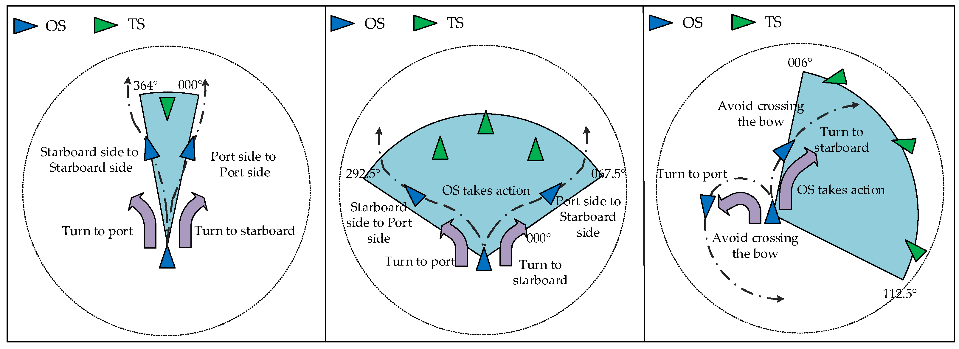
To construct the collision avoidance decision azimuth map, this study takes as the research object the ships that executed an avoidance maneuver and treats each of them as the own ship, so that the decision patterns adopted under different encounter scenarios can be analyzed. According to rules 13 to 17 of the COLREGs, when two ships are in an overtaking situation, the overtaking ship shall keep out of the way of the ship being overtaken, while the overtaken ship shall maintain her course and speed; when two ships are in a head-on situation, both ships shall alter course to starboard so as to pass port-to-port; when two ships are in a crossing situation, the give-way ship shall keep out of the way of the stand-on ship by passing astern and shall avoid crossing ahead of the target ship, while the stand-on ship shall maintain her course and speed. The rules further stipulate that, when a ship required to maintain course and speed detects that the give-way ship is not taking appropriate action, it may take independent action to avoid collision.
It can therefore be seen that the responsibilities of ships in overtaking, head-on, and crossing situations evolve with the spatiotemporal relationship of the encounter. This is particularly evident in overtaking and crossing, where the action logic should be further distinguished between the ship being overtaken and the stand-on ship. Moreover, even within the same encounter situation, ships may adopt different avoidance decisions. In general, the own ship’s action can be categorized into four passing modes: passing on the target ship’s port side, passing on the target ship’s starboard side, passing ahead of the target ship, and passing astern of the target ship. In a head-on situation, the two ships may both alter their course to starboard and pass port-to-port or both alter to port and pass starboard-to-starboard. In an overtaking situation, when the own ship is overtaking the target ship, it may overtake by altering to port to pass on the target ship’s port side or overtake by altering to starboard to pass on the target ship’s starboard side. In a crossing situation, the own ship may alter to starboard and pass ahead of the target ship, or it may alter to port and swing around to pass astern of the target ship. Although the specific intentions and obligations differ across encounter situations, the essence of the maneuver is a course alteration to port or to starboard to avoid collision. For this reason, this study takes “turning to port” and “turning to starboard” as the two concrete maneuvering actions of the ship, and the action intentions for each encounter situation are illustrated in Figure 6.
Accordingly, when ship actions are used as the classification label, partitioning the relative motion features involved in collision avoidance actions becomes a typical binary classification problem. To comprehensively analyze and evaluate the influence of the encounter state on action selection, this study employs a decision tree model to explore the latent relationships between ship collision avoidance actions and the corresponding relative motion parameters.

3.5.2. Decision Tree Model

At present, classification algorithms can be broadly divided into linear and nonlinear approaches. Linear classifiers mainly include Logistic Regression (LR) [43] and Linear Discriminant Analysis (LDA) [44]. Nonlinear classifiers typically comprise the k-nearest neighbor (KNN) algorithm [45], the Naive Bayesian model (NBM) [46], support vector machines (SVMs) [47], and decision trees (DTs) [48].
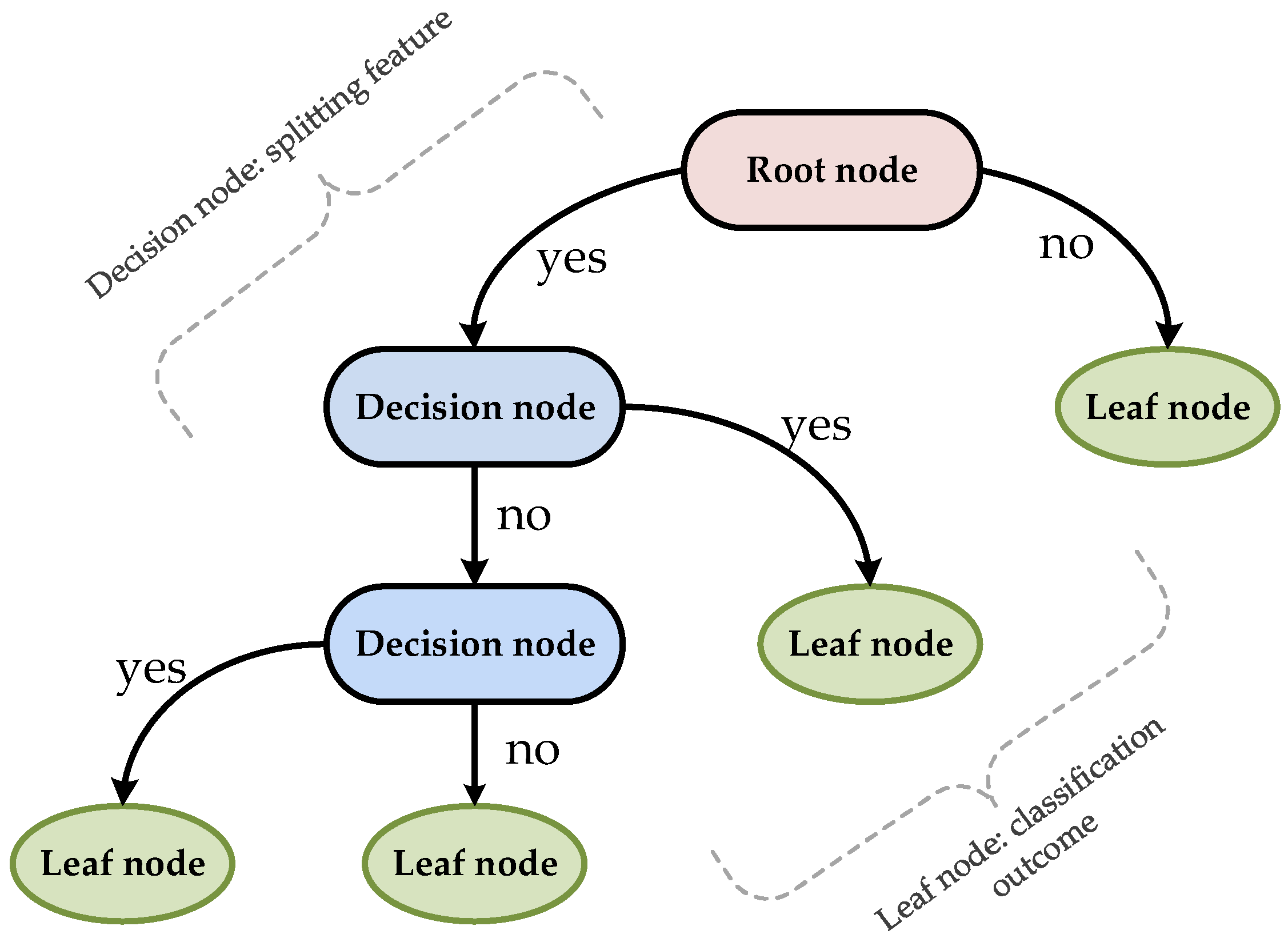
Among these methods, the decision tree is a supervised learning approach whose core idea is to achieve classification or prediction through a sequence of feature-based tests, and its algorithmic structure is transparent and easy to interpret. As illustrated in Figure 7, a typical decision tree consists of a root node, several decision nodes, and multiple leaf nodes. Starting from the root node, the algorithm successively selects the feature and corresponding split threshold that best separates the samples; at each decision node, the sample is tested against this condition and then routed to the next node along the corresponding branch, until a leaf node is reached, at which point the final class label is assigned.
In this study, the Classification and Regression Tree (CART) algorithm is adopted to partition ship collision avoidance action patterns. The ship avoidance action dataset e p s = { e p 1 , e p 2 , , e p n } is used as the input for model construction, where each sample e p i contains the distance S , the bearing AOB, the direction of relative motion r , and the corresponding maneuver label a c t i o n . The relative motion parameters ( S ,   AOB ,   r ) are taken as the classification features, and the maneuver a c t i o n is taken as the class label. The input dataset (D) for the model can therefore be expressed as Equation (2).
D = x i , y i | i = 1 , , n
where
x i = [ x 1 i , x 2 i , , x M i ]
In the formula, n denotes the total number of samples, M denotes the dimensionality of the feature space, x i denotes the feature set of the i -th sample, x j i denotes the value of the j -th feature of the i -th sample, and y i denotes the class label of the i -th sample.
Compared with conventional decision trees, the CART (Classification and Regression Tree) algorithm proposed by Chen et al. [49] uses the Gini index to measure the impurity between feature partitions, which enables it to capture nonlinear relationships and decision boundaries among multiple features while maintaining high interpretability. In addition, during model tuning, pruning can be applied to effectively prevent overfitting, thereby giving the model stronger adaptability, higher accuracy, and better generalization. The Gini index of the CART decision tree is calculated as Equations (4) and (5):
G i n i - i n d e x ( D , a ) = G i n i ( D ) D v D G i n i ( D v )
G i n i ( D ) = 1 p 2 x

4. Results

4.1. Study Area and Data

The AIS data used in this study were collected from 1 May 2021 to 31 August 2023 in an open sea area located 143° southeast of the Yangtze River Estuary at 89.44 nm, with a square analysis window of 20 nm on each side, as shown in Figure 8.
In Figure 8, the longitudinal range of the study area is 122.897185° E–123.434147° E and the latitudinal range is 30.073853° N–30.486547° N. To ensure that the mined encounter trajectories reflect the characteristics of open waters and to exclude interference from small or poorly equipped fishing vessels, AIS data were selected from the summer fishing moratorium period (July–August) of 2021, 2022, and 2023. In total, 12 months of data were obtained, comprising 2,228,774 ship position records.
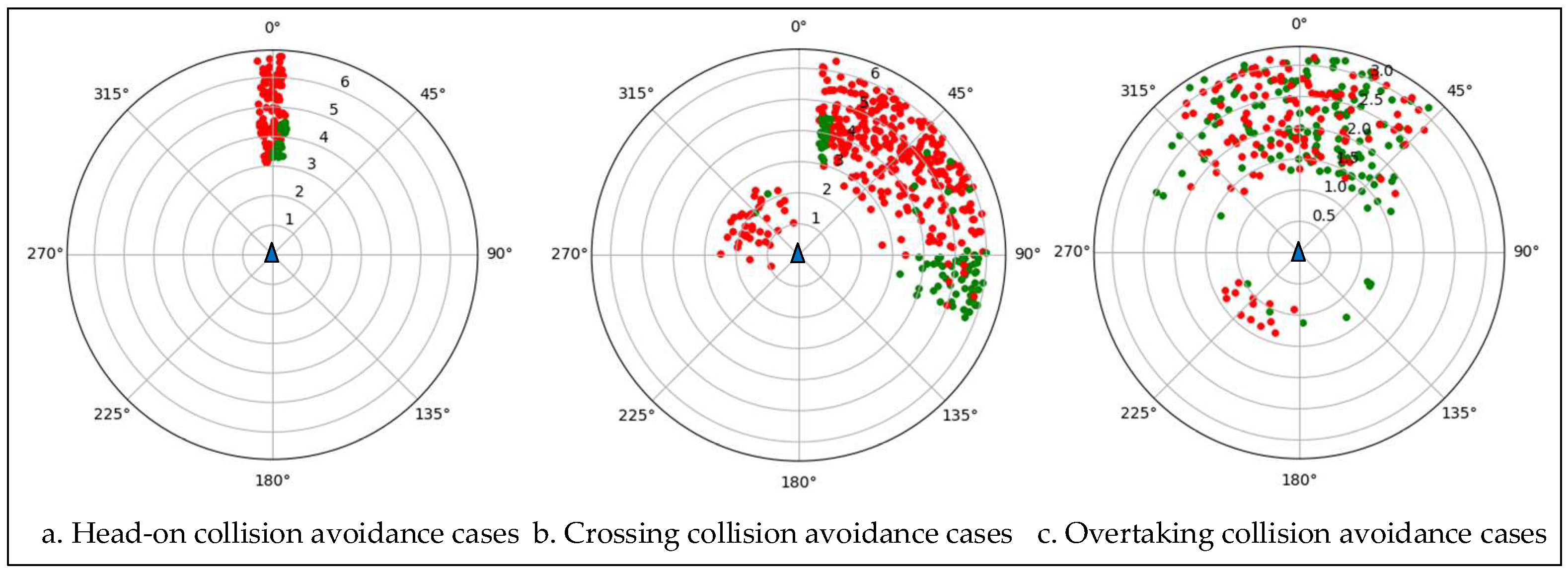
Based on the above data, the first-stage ship encounter recognition identified a total of 1658 encounter cases. In the second stage, collision avoidance decision points were extracted, yielding 827 valid avoidance cases. After standardizing the encounter scenarios and taking the ship that executed the avoidance maneuver as the reference, the polar distribution map of collision avoidance cases is shown in Figure 9.

4.2. Data Analysis

Based on the valid ship collision avoidance cases, the action types in the dataset were extracted as the target classes for model partitioning, and the data visualization is shown in Figure 10.
In Figure 10, from left to right, the plots correspond to collision avoidance data under head-on, crossing, and overtaking situations, respectively. Red points denote starboard alteration actions by the own ship, and green points denote port alteration actions. For the head-on and crossing situations, two patterns can be observed from the data: first, the two action types (turning to port and turning to starboard) exhibit clearly different bearing distributions, and one action type appears with a substantially higher frequency than the other; second, the chosen avoidance action is closely correlated with the bearing between the two ships.
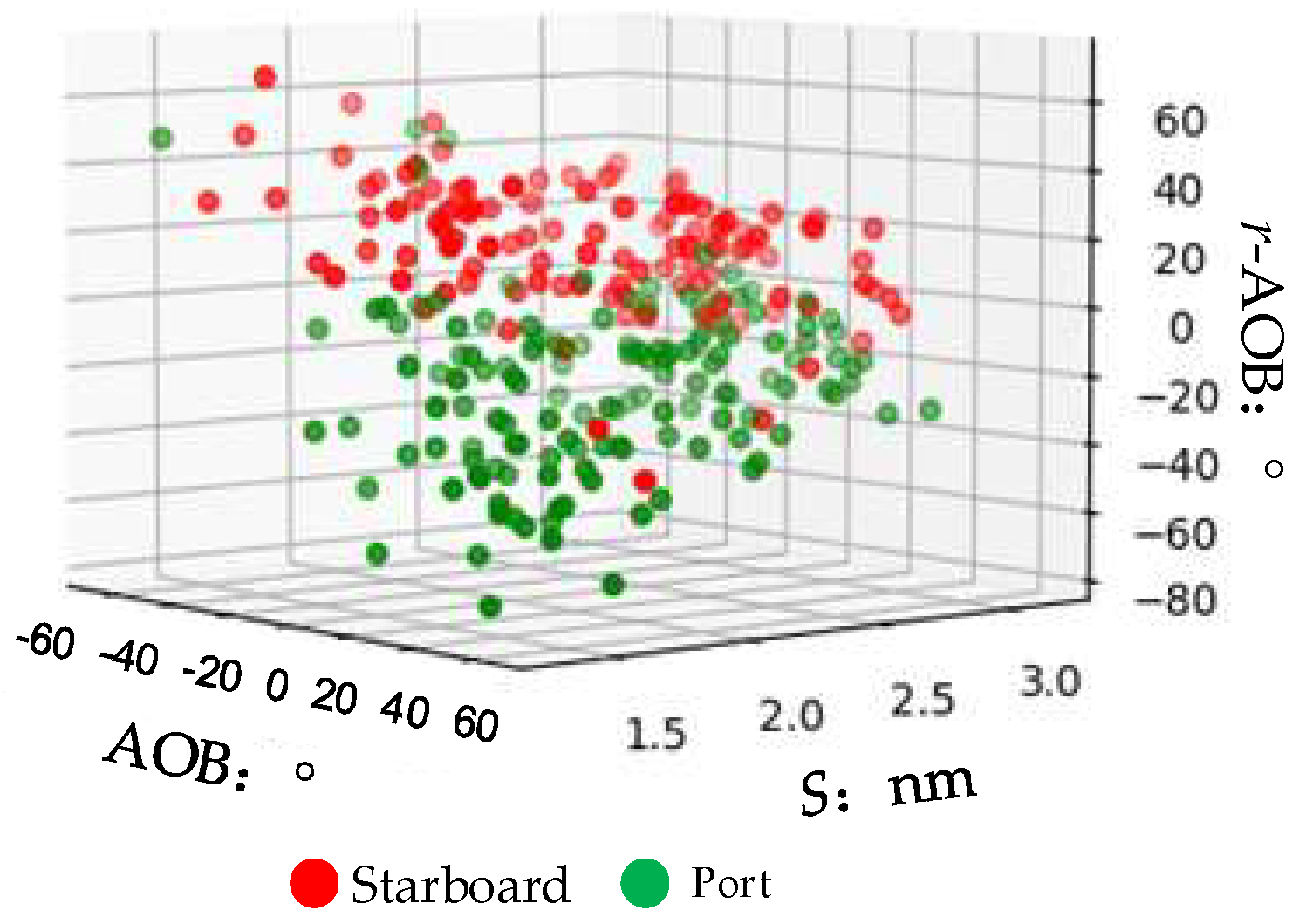
However, in the overtaking situation, the distribution of action types shown in Figure 10c is relatively mixed, and it is not possible to distinguish different collision avoidance actions solely from the bearing distribution. In other words, for the same bearing, the own ship may overtake the target ship either on its port side or on its starboard side. Therefore, after further analyzing the overtaking data in combination with navigation practice, the relative motion relationship between the two ships is introduced to better observe the characteristics expressed by the data. In addition to the bearing distribution, the difference between the direction of relative motion and the bearing ( r AOB ) is taken as a third evaluation feature, and it is combined with the distance and the bearing range to form the feature set for partitioning overtaking actions. The relationships between overtaking action types and these three evaluation features are plotted in Figure 11.
Figure 11 shows the distribution of collision avoidance actions when the own ship acts as the overtaking ship. After introducing the relationship between the direction of relative motion and the bearing, the distributions of the two overtaking actions (turning to port and turning to starboard) become clearly separated. This indicates that the choice of overtaking maneuver is strongly correlated with the three features of AOB, S, and r.
In summary, for crossing and head-on situations, the action classes of the own ship are “turning to port” and “turning to starboard,” and the features that influence the action choice are the S and AOB. For overtaking situations, the action classes of the own ship are likewise “turning to port” and “turning to starboard,” while the features that influence the action choice are the S , AOB, and r .

4.3. Encounter Situation Feature Partition

4.3.1. Head-On

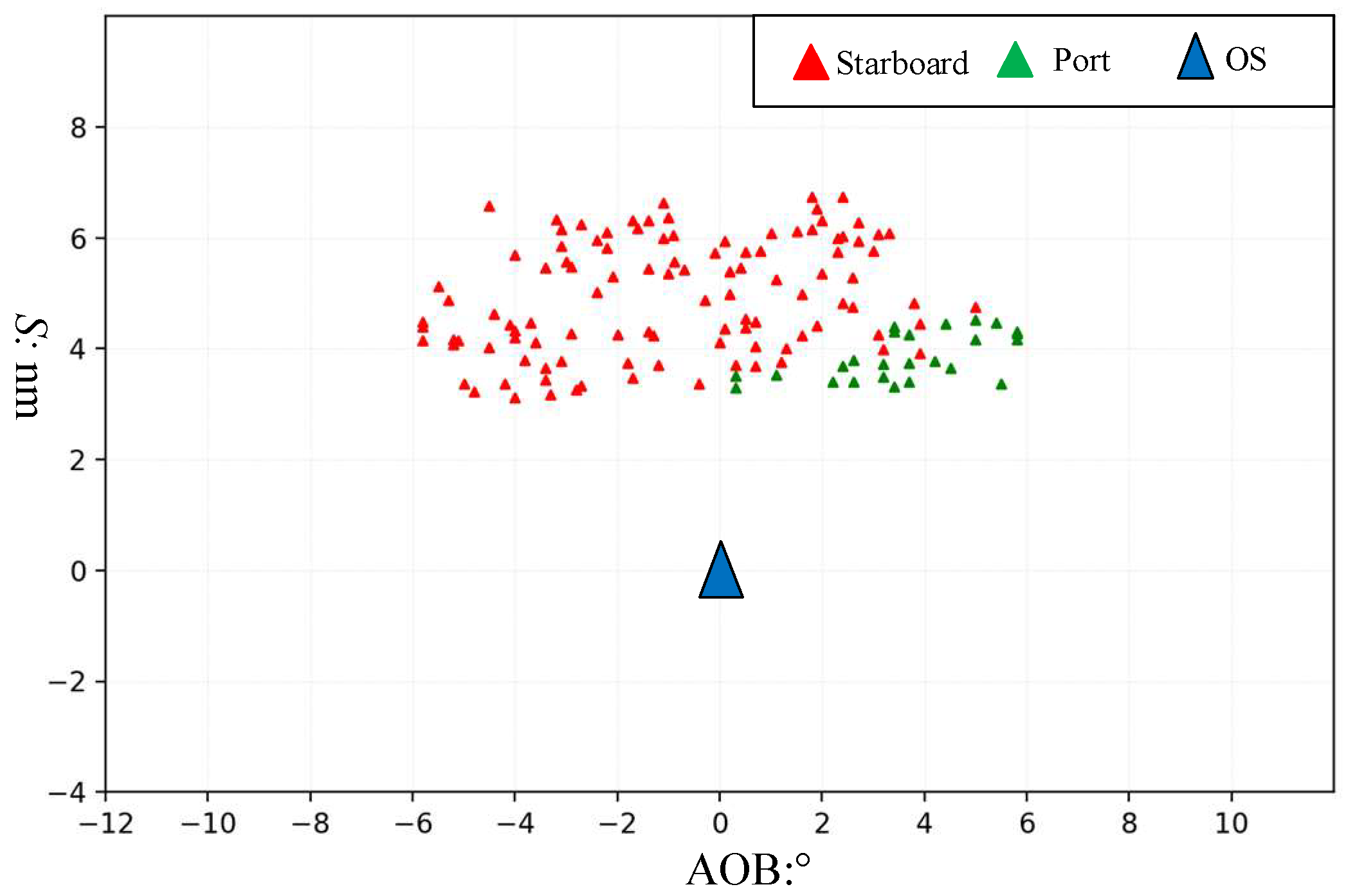
In total, 138 head-on encounter cases were collected in this study. Because the target ship’s bearing in head-on situations is distributed around the full circle, the polar distribution of ships in Figure 10a was converted, for easier model classification and visualization, into a Cartesian coordinate system in which the own ship is taken as the origin, the distance between the two ships is taken as the vertical axis, and the relative bearing range is taken as the horizontal axis. The resulting plot of the own ship’s maneuvering bearing and distance is shown in Figure 12.
Figure 12 illustrates the collision avoidance actions executed by the own ship under head-on situations in which both ships have an equal responsibility. In the figure, red points denote starboard alteration actions by the own ship, while green points denote port alteration actions. Based on the analysis in Section 4.2, the target ship’s bearing relative to the own ship (AOB) and the distance (S) are taken as the feature variables influencing the action choice, and the action actually taken by the own ship is used as the decision label to construct the dataset. A portion of the data is shown in Table 2.
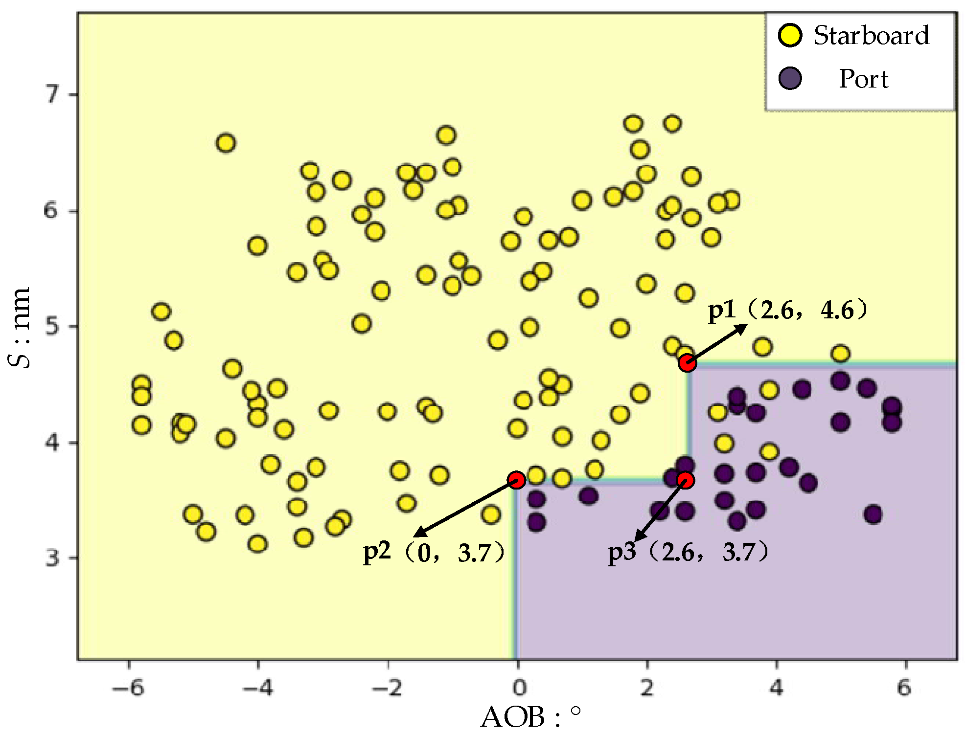
Figure 13 shows the distribution of decision boundary features for ship collision avoidance action in head-on situations, where the horizontal axis represents the bearing (AOB), the vertical axis represents the distance (S), and the color denotes the classification result.
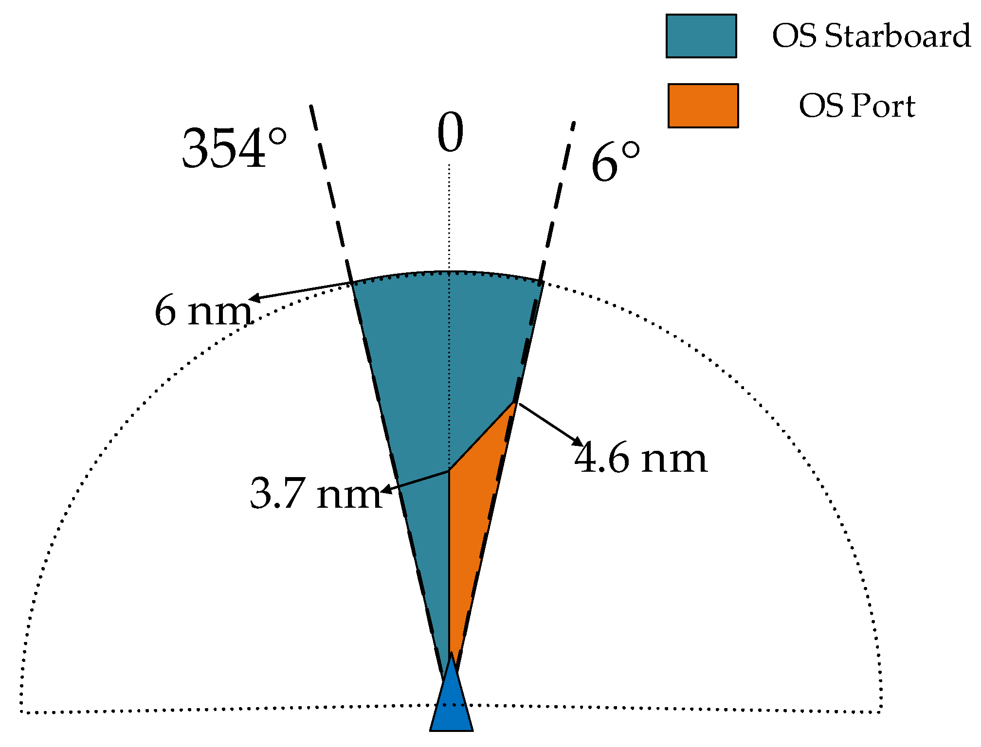
In Figure 13, yellow indicates starboard alteration actions and purple indicates port alteration actions. For subsequent quantitative analysis, three vertices of the decision boundary, denoted as p 1 , p 2 , and p 3 , are sampled, and the bearing and distance features contained in these three points are, respectively, p 1 ( A O B , S ) = ( 2.6 , 4.6 ) , p 2 ( A O B , S ) = ( 2.6 , 3.7 ) , and p 3 ( A O B , S ) = ( 0 , 3.7 ) . In head-on situations, when the encounter distance is greater than 4.6 nm, the own ship consistently adopts a starboard alteration strategy, which is independent of the target bearing and is consistent with the action requirement in rule 14 of the COLREGs. When the encounter distance is less than 4.6 nm, different collision avoidance decisions appear under different encounter feature combinations. For example, if the line between p 1 and p 2 is taken as the boundary, then, when the encounter distance is between 3.7 and 4.6 nautical miles and the target ship is located on the starboard side of the own ship with a bearing greater than 2.6°, most ship officers choose to alter to port; otherwise, they alter to starboard. Moreover, Figure 13 shows that, as the encounter distance decreases, the bearing range within which the own ship adopts a port alteration action gradually expands.
In the COLREGs, it is stipulated that, when two ships are in a head-on situation, both shall make a substantial alteration to starboard to keep clear. However, in the real collision avoidance cases collected in this study, there exist avoidance maneuvers that deviate from the COLREGs. Specifically, when the distance between the two ships decreases and the target ship is located on the starboard side of the own ship, simultaneous port alterations by both ships become particularly evident. Such deviations are not occasional operations made by one or two individual officers; there must be underlying causes. The deviation clauses in the COLREGs state that when, in order to avoid immediate danger, compliance with the rules would not be sufficient to avert the danger and a departure from the rules may better prevent a collision or navigational accident, such a departure is permitted. Therefore, the deviation samples identified in the data are analyzed in conjunction with practical operating conditions, as shown in Figure 14.
In navigational practice, among the three encounter situations, the head-on encounter usually involves the highest relative approach speed and therefore presents the greatest urgency. Figure 14a shows the case where the target ship appears on the port side of the own ship at a long range; in this situation, both ships can make a starboard alteration and clear each other with ease. In Figure 14b, the target ship appears on the starboard side of the own ship at a long range; in this situation, the two ships can still avoid collision by making a larger starboard alteration, but under otherwise identical conditions the urgency of the action in 14b is higher than that in 14a. Figure 14c shows the case where the target ship is on the port side at a short range; here, a substantial turn to starboard by both ships is an effective avoidance decision. Figure 14d,e show the case where the target ship is on the starboard side at a short range. A comparison of the two subfigures shows that, at this bearing, if both ships still alter to starboard, the relative closing speed will continue to increase, and, considering that some ships may not be able to achieve the required turning rate at a short range due to action limitations, this may lead to a collision. By contrast, if both ships alter to port at this bearing, the encounter can be mitigated in the same way as in Figure 14c, effectively reducing the urgency of collision avoidance. The action illustrated in Figure 14e is exactly the COLREG-deviating action observed in real cases. Therefore, compared with Figure 14d, the mutual port alteration in Figure 14e should be regarded as a more effective action. On this basis, the collision avoidance action decision-making azimuth map for head-on situations is constructed as shown in Figure 15.

4.3.2. Crossing

In crossing situations, the ship on the port side is normally required to keep out of the way, while the ship on the starboard side is the stand-on vessel and should maintain her course and speed. However, when the stand-on vessel detects that the give-way vessel is not taking action in accordance with the COLREGs, it may take independent action to avoid a collision. A total of 414 crossing encounter samples were collected, as shown in Figure 16.
Figure 16a shows the actions taken when the own ship was the give-way ship, with a total of 375 samples. Figure 16b shows the evasive actions taken when the own ship was the stand-on ship and detected that the target ship did not act in accordance with the COLREGs, with 39 samples. Data analysis indicates that, under crossing situations, the classification of the own ship’s action types is the same as in head-on situations. The target bearing (AOB) and the distance (S) are used as the partitioning features, and the action actually taken by the own ship is used as the sample label. Table 3 and Table 4 list portions of the sample data for the give-way ship and the stand-on ship, respectively.
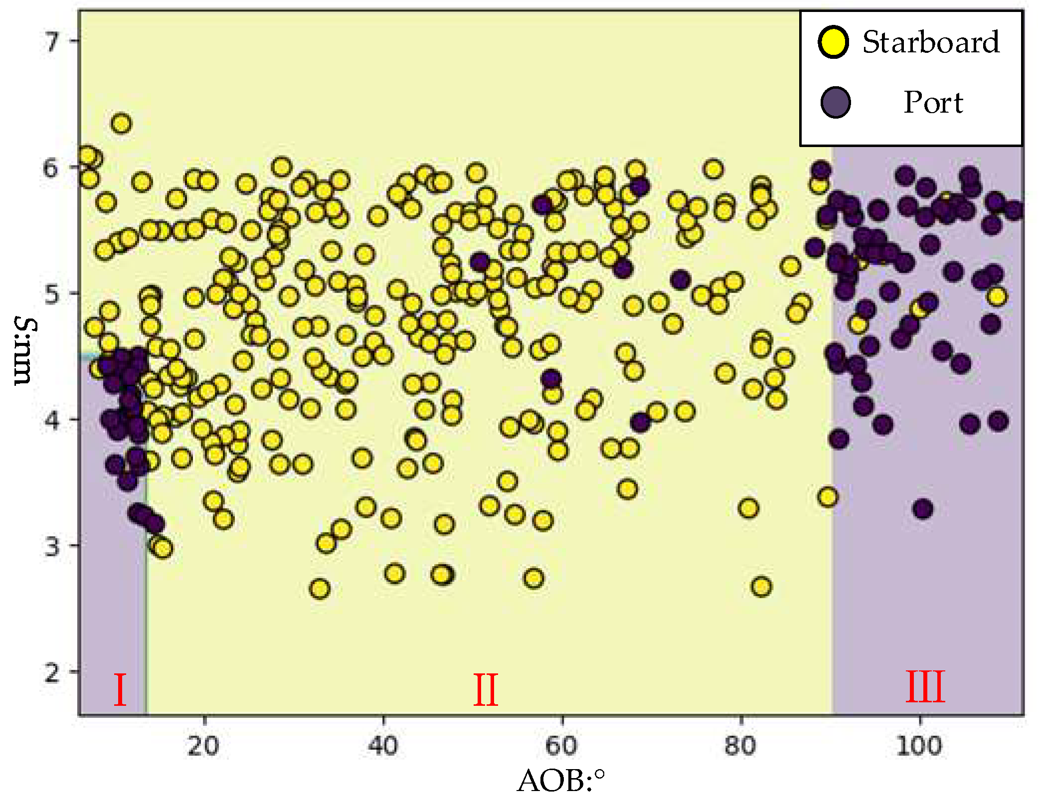
When the own ship is the give-way ship, its collision avoidance actions vary with the target bearing; however, when the own ship is the stand-on ship, its actions are relatively uniform, with the vast majority being starboard alterations. First, for the case where the own ship is the give-way ship, a decision tree-based partitioning of action types is performed, and the resulting decision boundary is shown in Figure 17.
In Figure 17, the decision boundary is clearly divided into three intervals, denoted as I, II, and III. In terms of relative bearing, distance, and action type, intervals I and III correspond to port alteration actions by the own ship. Interval I covers the cases where the target ship is within the own ship’s bearing range of 6–13.6° and the distance S is less than 4.5 nm. Interval III covers the cases where the target ship is within the bearing range of (90.3°–112.5°], in which case the action is independent of the distance between the two ships. Interval II corresponds to starboard alteration actions by the own ship, with the feature range defined as ( AOB [ 6 ° , 13.6 ° ]   and   S 4.5   NM ) ( AOB ( 13.6 ° , 90.3 ° ] ) .
Among all collected cases, crossing accounts for the largest proportion, which makes them more suitable for uncovering latent patterns of collision avoidance actions from data. The COLREGs stipulate that, in a crossing situation, the give-way ship shall keep out of the way and, where circumstances permit, shall avoid crossing ahead of the other ship. However, the actual behavior of give-way ships in the collected cases (as shown in Figure 18) reveals some deviations. In Figure 18a, when the target ship approaches within interval I—that is, on the starboard side of the own ship, at a short range, and with a small relative bearing angle—most officers choose to alter to port and turn behind the target ship. At this relative bearing, if the own ship were to alter to starboard, the small encounter distance and the ship’s action limits might lead to a small cpa, and the starboard turn would also increase the relative closing speed, making the situation more urgent. In Figure 18c, when the target ship approaches within interval III—namely, around the starboard beam of the own ship—most officers likewise choose to alter to port and pass astern. If the own ship were to alter to starboard at this bearing, the approach speed between the two ships would rise rapidly, which is unfavorable for safe avoidance. In Figure 18b, when the target ship approaches within interval II, the own ship consistently alters to starboard to avoid collision, and this action is consistent with the COLREGs and with good seamanship practice.
For crossing situations in which the own ship is the stand-on ship, the COLREGs stipulate that, when the stand-on ship detects that the give-way ship is not taking appropriate action, it may take independent action to avoid collision, while, where circumstances permit, it shall not alter course to port for the target ship on its own port side. In the dataset shown in Figure 16b, a total of 37 collision avoidance cases of stand-on ships were collected. In all these cases, the own ship took action at a distance of less than 2.5 nm; 35 cases adopted a starboard alteration, and only 2 cases adopted a port alteration. These results indicate that the vast majority of officers conducted collision avoidance actions in accordance with the COLREGs. The few port alteration cases are considered accidental, and their proportion is very small, so they are not included in the discussion of general collision avoidance patterns in this paper.
To conclude, the collision avoidance action decision-making azimuth map for crossing situations is constructed as shown in Figure 19.

4.3.3. Overtaking

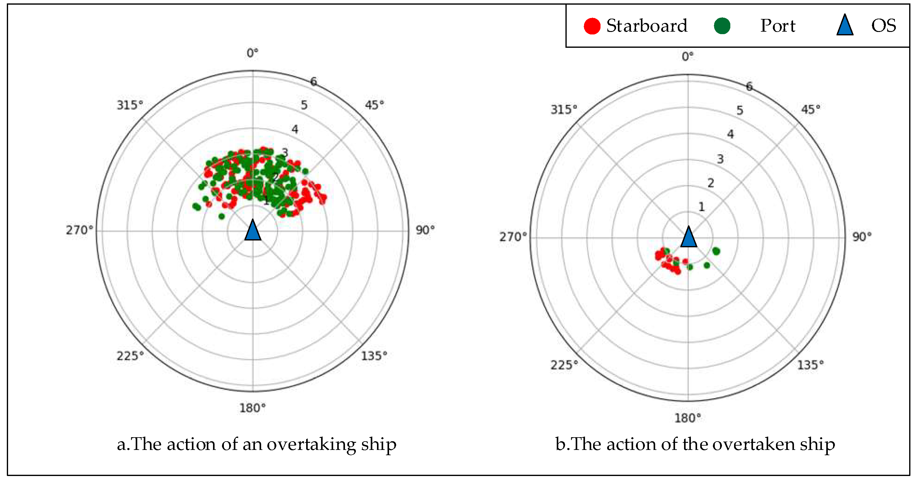
In the COLREGs, ships in an overtaking situation are divided into the overtaking ship and the ship being overtaken, and the overtaking ship is required to keep out of the way. For overtaking encounters, a total of 275 cases were collected, and their data distribution is shown in Figure 20.
Figure 20 shows the relative position distributions of two ships in overtaking situations. Figure 20a presents the collision avoidance decisions made by the overtaking ship, with a total of 254 samples, and Figure 20b presents the collision avoidance decisions made by the ship being overtaken, with 21 samples collected. Table 5 and Table 6 list portions of the dataset, including relative bearing (AOB), distance (S), direction of relative motion (r), and the corresponding action labels.
First, the action types of the own ship acting as the overtaking ship are partitioned. As analyzed in Section 4.2, for overtaking situations, the direction of relative motion (r) plays a decisive role in differentiating collision avoidance actions. Therefore, in this subsection, the relationship between r and the relative bearing (AOB) is introduced, in conjunction with navigation practice, to reset the feature representation of the samples, so as to provide a more comprehensive description of the feature partitioning for ship action selection. The feature partitioning of the overtaking dataset is as follows:
Since the bearing range in overtaking situations is similar to that in head-on situations and is subject to circular wrapping, the data are first converted into a Cartesian coordinate system to facilitate subsequent visualization. The difference between the direction of relative motion ( r ) and the relative bearing ( AOB ) is then calculated, that is, r-AOB. As a result, the final features used for partitioning include the bearing, the distance S , and r-AOB, while the sample label remains the action taken by the own ship. A portion of the dataset is shown in Table 7.
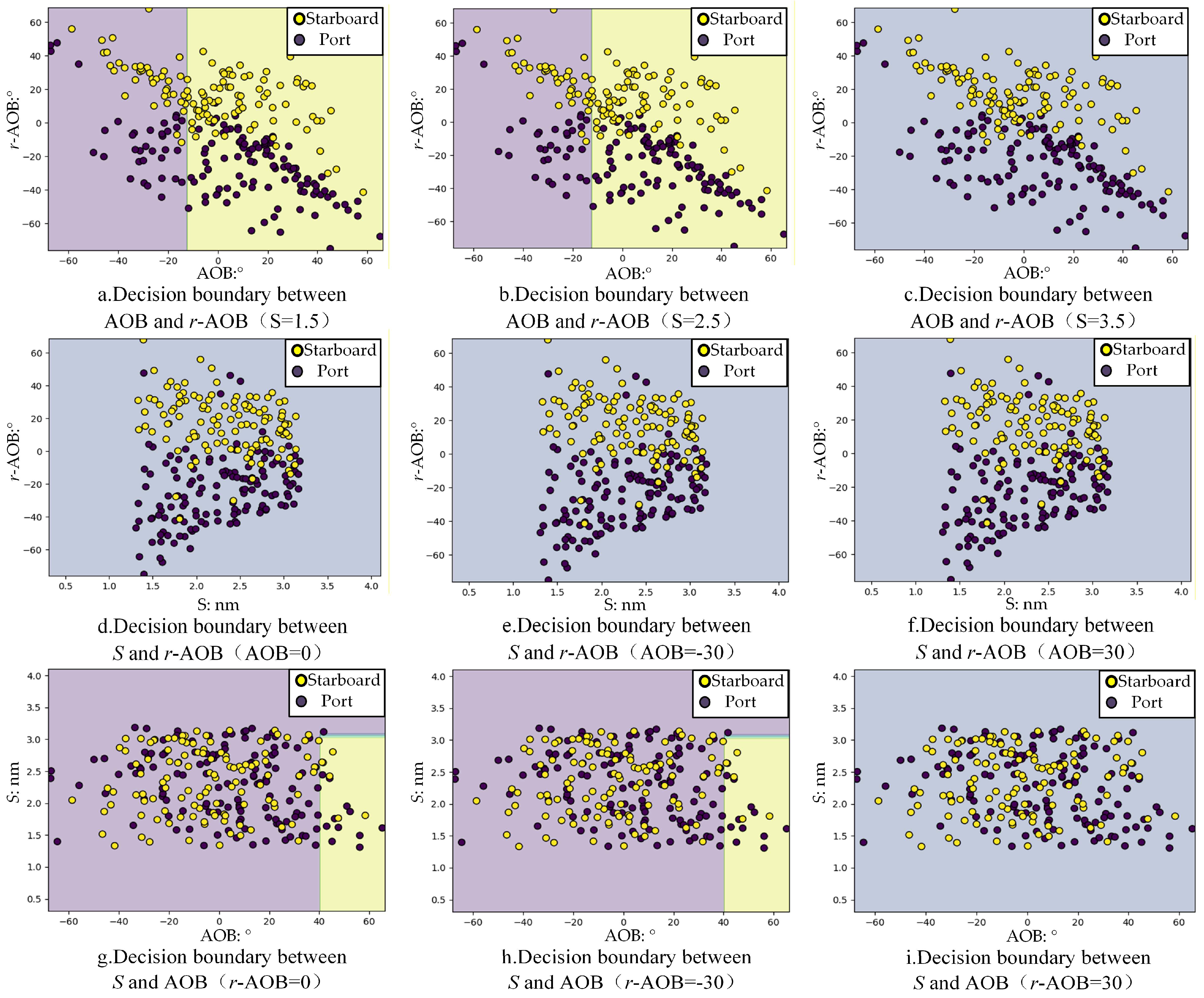
Unlike the head-on and crossing datasets, the overtaking dataset consists of three features. To facilitate visualization and interpretation, the influence of the model on action selection is examined under pairwise feature combinations. Using the decision tree model to partition the overtaking actions, the resulting decision boundaries are shown in Figure 21.
From Figure 21, it can be observed that the pairwise combinations of features—AOB and r-AOB, S and r-AOB, and AOB and S —do not exhibit a strong correlation with the action type. By contrast, when considering only the single indicator r-AOB, the action of the own ship shows a much clearer and more regular distribution.
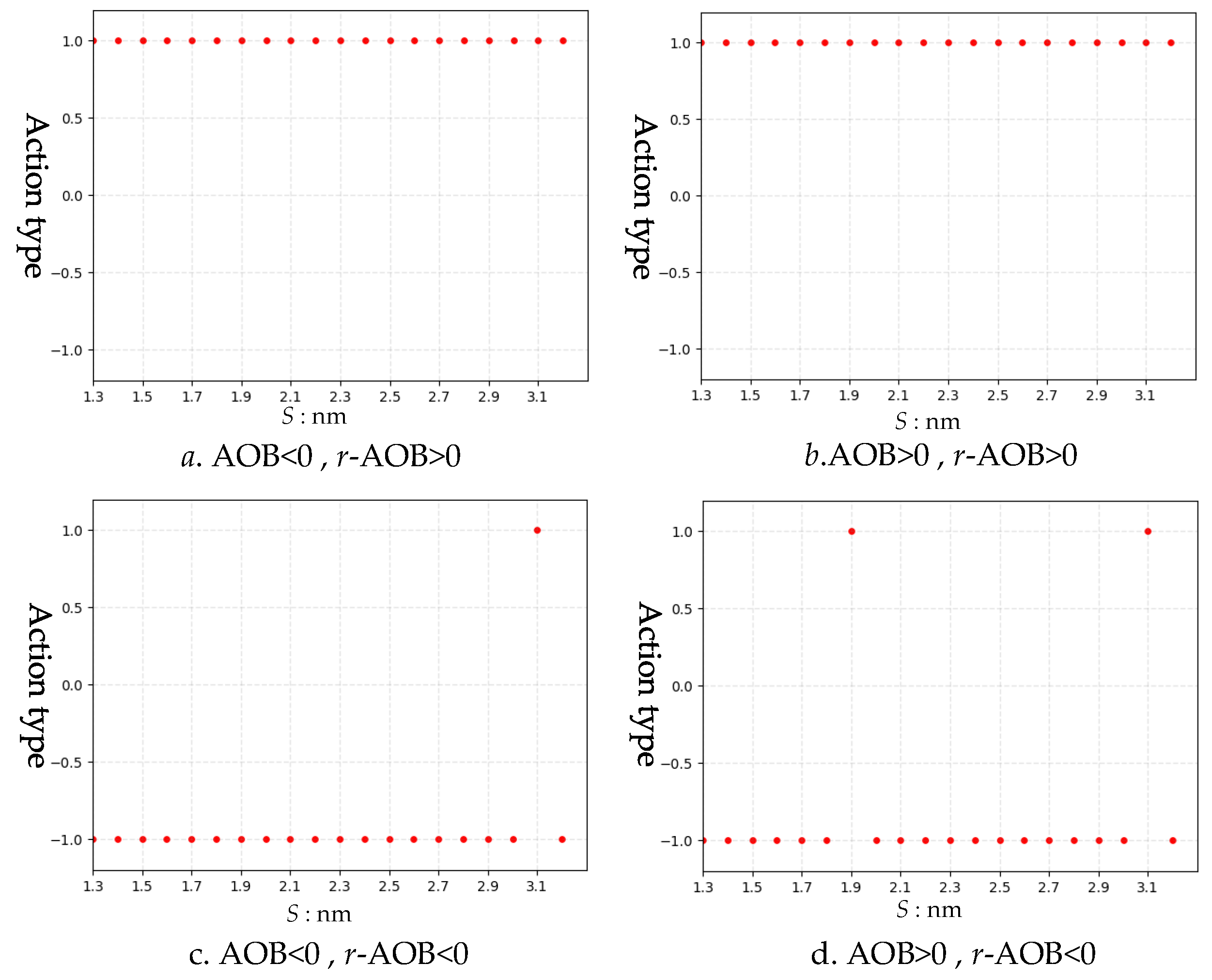
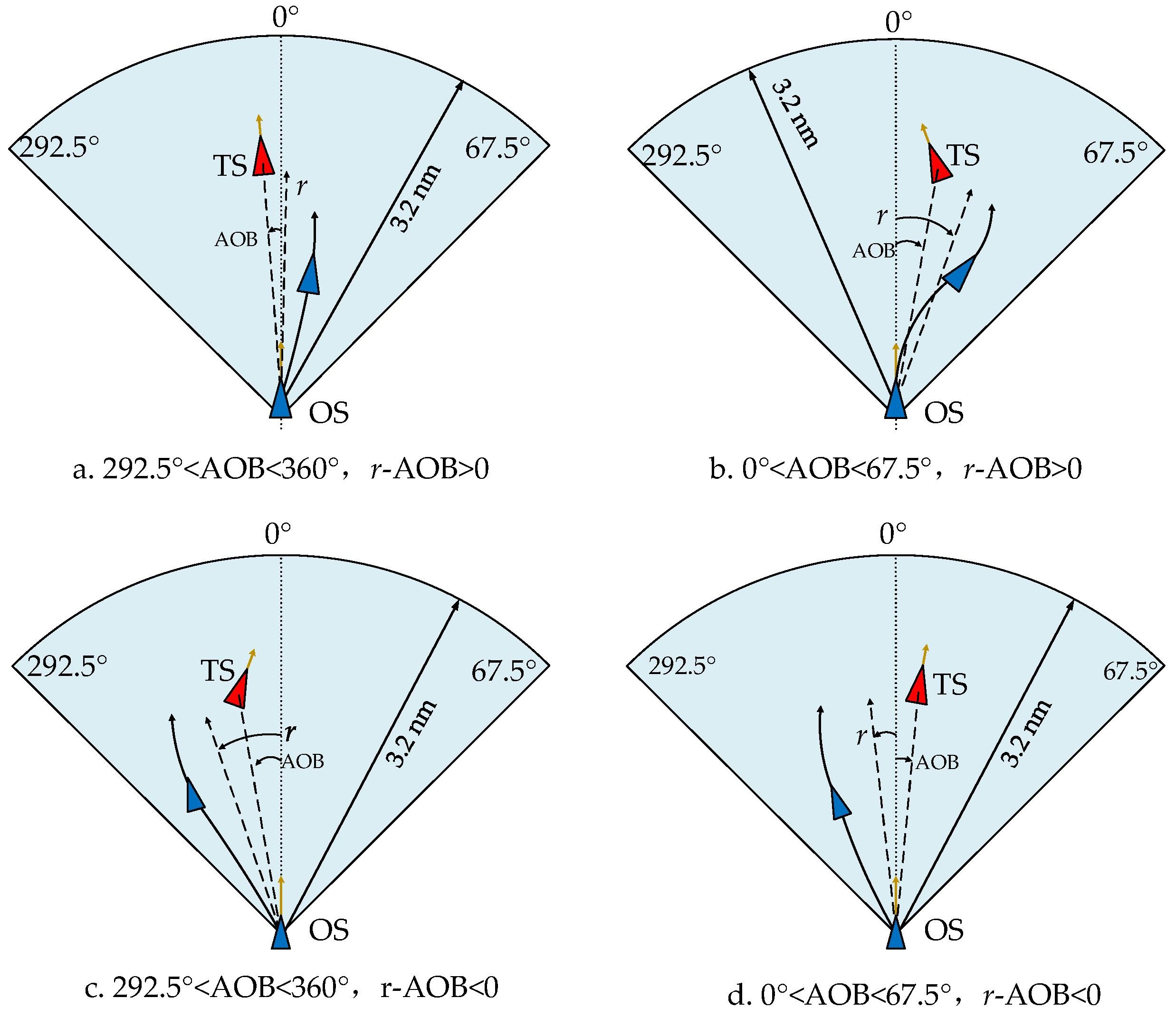
To explore the latent association between the features of the overtaking dataset and the ship’s action selection, the partitioned features need to be examined in greater depth. When the AOB is greater than 0, the target ship is located on the starboard side of the own ship; conversely, when the AOB is less than 0, the target ship is located on the port side. Since r-AOB represents the difference between the direction of relative motion (r) and AOB, a value of r-AOB > 0 indicates that the direction of relative motion lies to the right of the relative bearing, whereas r-AOB < 0 indicates that the direction of relative motion lies to the left of the relative bearing. Thus, the two features can jointly form four combinations: [AOB < 0, r-AOB > 0], [AOB > 0, r-AOB > 0], [AOB < 0, r-AOB < 0], and [AOB > 0, r-AOB < 0]. By taking these four combinations of AOB and r-AOB together with the actual overtaking distance interval, 1.3 ,   3.2   nm , as the model inputs, a resampling was carried out based on the classification model. Within each of the four combinations, AOB and r-AOB were randomly sampled, while the distance S was sampled at 0.1 nm intervals. The model output was the overtaking action of the own ship, where overtaking on the port side of the target ship was encoded as −1 and overtaking on the starboard side of the target ship was encoded as 1. The prediction results are shown in Figure 22.
It can thus be clearly seen from Figure 22 that distance has only a minor influence on overtaking actions. Once the target’s relative bearing and the direction of relative motion are determined, the overtaking action of the ship tends to be consistent; likewise, when the interval of r-AOB is fixed, the overtaking action also converges to a single pattern. For Figure 22a,b, all sampled results are 1, indicating that the ship overtakes on the starboard side of the target ship. For Figure 22c,d, apart from a few outliers, the sampled results are all −1, indicating that the ship overtakes on the port side of the target ship. Therefore, the influence of the three features S , AOB, and r-AOB on the overtaking actions of the own ship can be summarized as follows, and Figure 23 shows the corresponding overtaking strategy.
  • When the own ship is the overtaking ship, the overtaking action is initiated at a distance of less than 3.2 nm.
  • If the target ship is on the port side of the own ship and the direction of relative motion lies to the right of the relative bearing, the overtaking vessel alters to starboard.
  • If the target ship is on the starboard side of the own ship and the direction of relative motion lies to the right of the relative bearing, the overtaking ship alters to starboard.
  • If the target ship is on the port side of the own ship and the direction of relative motion lies to the left of the relative bearing, the overtaking ship alters to port.
  • If the target ship is on the starboard side of the own ship and the direction of relative motion lies to the left of the relative bearing, the overtaking ship alters to port.
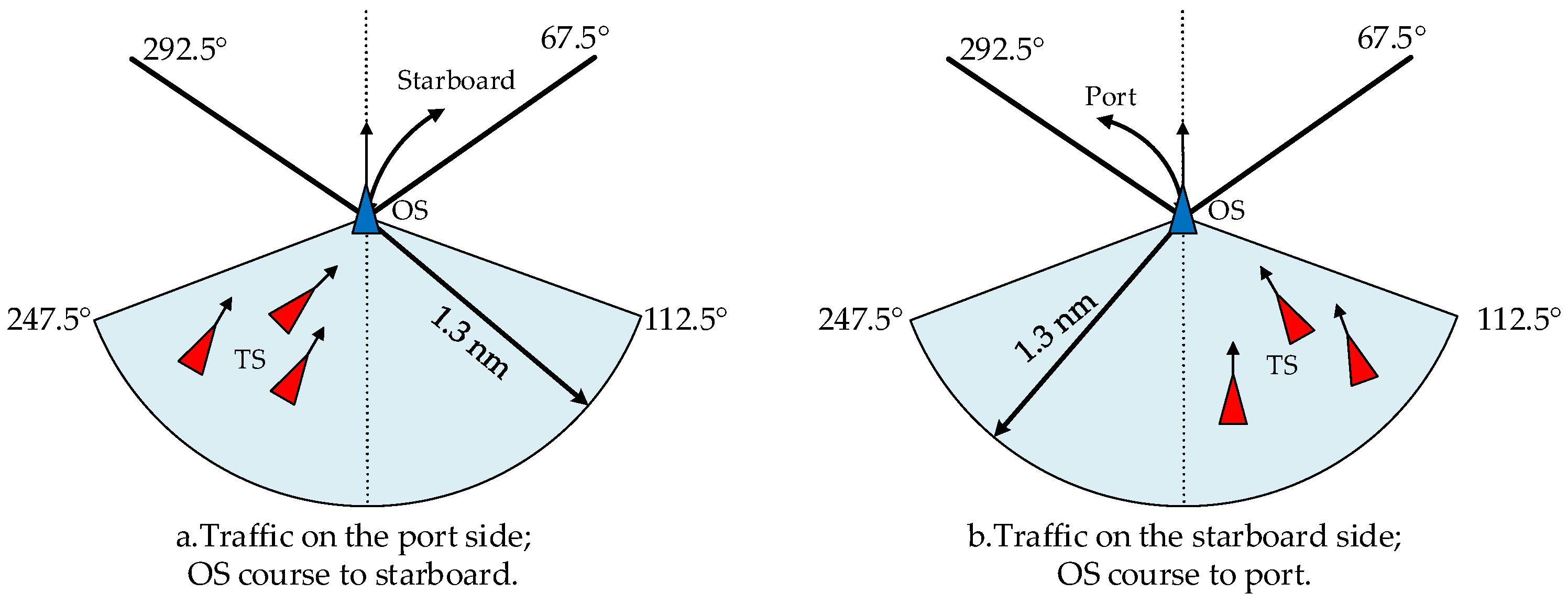
For the ship being overtaken, only 21 cases were collected. An examination of these records shows that, when the ship being overtaken detected that the overtaking ship was not taking appropriate actions in accordance with the rules, its avoidance actions were initiated at very short ranges, within 0.8–1.3 nm, which is shorter than in the other two encounter situations. In Figure 24a, when the overtaking ship approached from the port quarter of the ship being overtaken, most officers altered to starboard. In Figure 24b, when the overtaking ship approached from the starboard quarter, the officers altered to port. The essential logic behind both types of actions is to turn away from the approaching ship.

4.4. Data-Driven Ship Collision Avoidance Action Decision-Making Azimuth Map

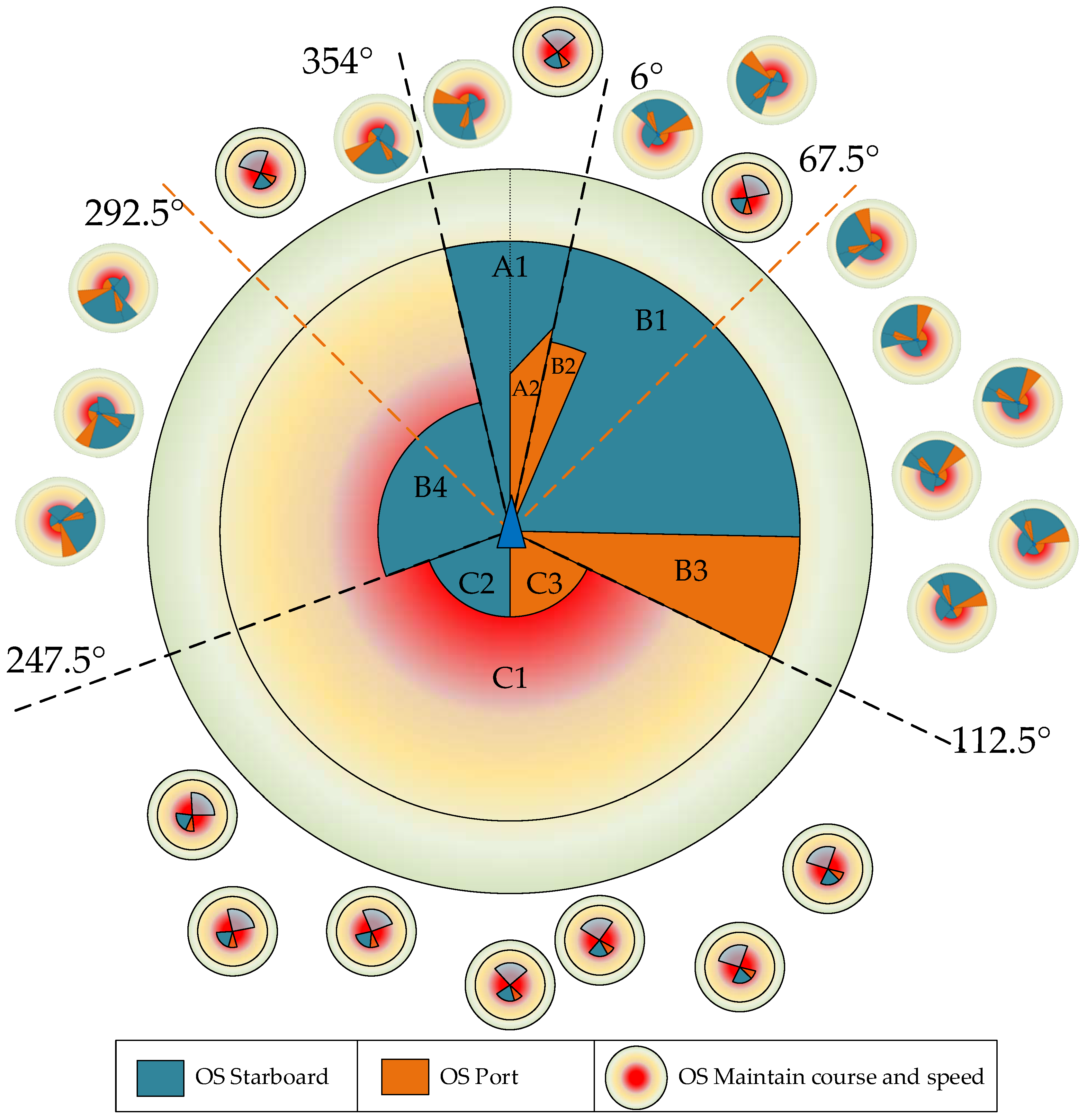
Drawing on the analyses in Section 4.3 and starting from real encounter cases, the action patterns of ships under different encounter situations are partitioned according to their encounter features, and a ship collision avoidance action decision-making azimuth map is thereby constructed (see Figure 25). The corresponding auxiliary parameter descriptions are given in Table 8.
As shown in Figure 25 and Table 8, by mining the actual collision avoidance behaviors contained in AIS data and classifying them by action type, the encounter-related provisions in the COLREGs are further refined and the ambiguities in encounter situation classification and action definition are concretized. When two ships form an encounter, the decision map first determines the encounter scenario and, accordingly, the allocation of responsibilities. The ship that is required to keep out of the way then performs the avoidance action indicated by the decision map, while the other ship maintains course and speed until the close-quarters situation is cleared. If the stand-on ship detects that the give-way ship has not taken appropriate action, it should, according to the same decision map, initiate the corresponding avoidance action once a certain encounter state is reached.

5. Discussion

This paper, based on navigation scenarios in open waters, uses a data-driven approach grounded in observed facts to provide a more fine-grained classification of ship encounter states and to offer corresponding collision avoidance decision guidance for two ships under different encounter situations.
Once the ship that is obliged to keep out of the way in the encounter situation is determined, most of the obtained results are consistent with the requirements of rules 13–17 of the COLREGs, indicating that the collision avoidance decisions taken by the majority of officers are essentially rule-based. However, because the proposed collision avoidance azimuth map is derived entirely from objective data, some conclusions exhibit departures from the COLREGs, such as port alteration actions in head-on situations. These departures are not accidental operations by a few individuals, but common patterns present in part of the sample, and the data suggest that, under certain specific circumstances, such departures can in fact be more conducive to navigational safety. For ships that, after the encounter situation is determined, are required to maintain course and speed, taking independent action too early does not conform to good seamanship; an analysis of the cases in which stand-on ships did take independent action reveals both the timing and the form of such actions.
The collision avoidance action decision azimuth map summarized from objective AIS evidence can therefore provide targeted guidance for the vast majority of encounter scenarios. It also offers an objective basis for the quantitative refinement of encounter state classifications and for assisting officers in collision avoidance decision-making.
However, this study has several limitations that call for further improvement and exploration:
First, the spatial scope of the study area is relatively small, and the sample overall represents a typical open water scenario with no obvious fairway constraints and a medium traffic density. Variables such as traffic density and multi-ship interference were not introduced, nor were behavioral differences compared between high- and low-density traffic or between constrained and open waters. Accordingly, the collision avoidance distances, action timing, and bearing partitions obtained in this paper are more applicable to similar open water contexts; in channel-constrained waters such as the Singapore Strait, the Port of Shanghai, or the Port of Rotterdam, behavioral patterns may differ significantly. In future research, on the one hand, AIS samples can be grouped by “high-/low-density” and “constrained/unconstrained” conditions to compare collision avoidance decision azimuth maps across scenarios; on the other hand, it is necessary to incorporate navigation samples from waters governed by different routing schemes to construct a more comprehensive collision avoidance decision azimuth map.
Second, the constructed collision avoidance decision azimuth map pertains only to two-ship encounters, and the recommendations are limited to course alteration schemes at certain key phases between two ships; it cannot provide guidance for the entire avoidance process. In principle, changes in the two ships’ speeds during avoidance can also be distilled and modeled mathematically to build a maneuvering model of the full encounter process (avoidance and return to course) based on the collective behavior of watch officers, thereby better facilitating the future application and implementation of artificial intelligence in ship collision avoidance.
Finally, the azimuth map is applicable to collision avoidance decisions between two ships, whereas the model fails for multi-ship encounters. Therefore, our future work will explore encounter situations and processes of greater complexity and will also consider interference from natural factors such as wind, waves, and currents, as well as constraints of the geographical environment.

6. Conclusions

This paper proposes a collision avoidance decision method that incorporates the COLREGs and is derived from the collective wisdom of ship officers, and on this basis constructs a ship collision avoidance action decision azimuth map. First, a two-stage procedure is designed to extract ship collision avoidance behaviors from AIS data: in the first stage, ship–ship encounter cases are identified from the full dataset, and, in the second stage, collision avoidance actions are mined from these encounter cases. Then, for different encounter scenarios, a decision tree algorithm is used to partition the latent relationships between ships’ relative motion parameters and their avoidance actions, thereby constructing a collective wisdom-based ship collision avoidance action decision azimuth map. This method, on the one hand, provides an objective basis for quantitatively enriching the COLREGs in practical applications and, on the other hand, offers a feasible idea for applying rapidly emerging artificial intelligence technologies to ship collision avoidance tasks.

Author Contributions

Conceptualization, Z.W. and F.S.; methodology, Z.W. and C.Z.; software, Z.W.; validation, Z.W., F.S., H.Y., and C.Z.; formal analysis, Z.W.; investigation, L.W.; resources, S.C.; data curation, Z.W.; writing—original draft preparation, Z.W.; writing—review and editing, Z.W. and H.Y.; visualization, Z.W.; supervision, H.Y.; project administration, Z.W.; funding acquisition, H.Y. All authors have read and agreed to the published version of the manuscript.

Funding

This work was supported by the National Natural Science Foundation of China (No. 42371415 and No. 42101429), the National Key Research and Development Program of China (No. 2024YFB4303603 and No. 2022YFC3302703), and the Young Elite Scientists Sponsorship Program by China Association for Science and Technology (CAST) (No. YESS20220491).

Data Availability Statement

Data available upon request due to restrictions due to privacy.

Acknowledgments

We sincerely thank the editor and the reviewers for their kind and helpful comments on this manuscript.

Conflicts of Interest

The authors declare no conflicts of interest.

References

  1. UNCTAD. 50 Years of Review of Maritime Transport, 1968–2018: Reflecting on the Past, Exploring the Future. 2018. Available online: https://unctad.org/webflyer/50-years-review-maritime-transport-1968-2018-reflecting-past-exploring-future#tab-2 (accessed on 25 October 2025).
  2. Zhang, J.; Zhen, K. A Review of Ship Collision Avoidance System. Sci. Technol. Eng. 2019, 19, 32–39. [Google Scholar] [CrossRef]
  3. Han, C.W.; Lee, S.W.; Jin, E.S. Tracking of ARPA Radar Signals Based on UK–PDAF and Fusion with AIS Data. J. Ocean. Eng. Technol. 2023, 37, 38–48. [Google Scholar] [CrossRef]
  4. Carl, M. Human Factors at Sea: Common Patterns of Error in Groundings and Collisions. Marit. Policy Manag. 2009, 36, 21–38. [Google Scholar] [CrossRef]
  5. Hasan, U.; Ismail, C. Analysis and Assessment of Ship Collision Accidents Using Fault Tree and Multiple Correspondence Analysis. Ocean. Eng. 2022, 245, 110514. [Google Scholar] [CrossRef]
  6. Hilgert, H. Defining the Close-Quarters Situation at Sea. J. Navig. 1983, 36, 454–461. [Google Scholar] [CrossRef]
  7. International Transport Workers’ Federation. Transport 2040: Impact of Technology on Seafarers—The Future of Work. 2019. Available online: https://commons.wmu.se/cgi/viewcontent.cgi?article=1091&context=lib_reports (accessed on 26 October 2025).
  8. Yu, H.; Wu, W.; Zhang, X.; Fang, Z.; Fu, X.; Xu, L.; Liu, J. Optimization-based global liquefied natural gas shipping network management for emission reduction. Ocean. Eng. 2025, 321, 120366. [Google Scholar] [CrossRef]
  9. Yu, H.; Cui, X.; Bai, X.; Chen, C.; Xu, L. Incorporating graph theory and time series analysis for fine-grained traffic flow prediction in port areas. Ocean. Eng. 2025, 335, 121693. [Google Scholar] [CrossRef]
  10. Kuwata, Y.; Wolf, M.T.; Zarzhitsky, D. Safe maritime navigation with COLREGS using Velocity Obstacles. IEEE J. Ocean. Eng. 2014, 39, 110–119. [Google Scholar] [CrossRef]
  11. Naeem, W.; Irwin, G.W.; Yang, A. COLREGs-based collision avoidance strategies for unmanned surface vehicles. Mechatronics 2012, 22, 669–678. [Google Scholar] [CrossRef]
  12. Zheng, Z.; Wu, Z. Research on decision-making of multi-ship meetings avoidance I. definition, division and classification of multi-ship meetings. Navig. Technol. 2000, 4, 9–12. [Google Scholar] [CrossRef]
  13. Wu, G.; Shi, D.; Guo, J. Deliberative collision avoidance for unmanned surface vehicle based on the directional weight. Shanghai Jiaotong Univ. (Sci.) 2016, 21, 307–312. [Google Scholar] [CrossRef]
  14. Kim, D.; Ahn, K.; Shim, S. A study on the verification of collision avoidance support system in real voyages. In Proceedings of the 2015 International Association of Institutes of Navigation World Congress (IAIN), Prague, Czech Republic, 20–23 October 2015. [Google Scholar] [CrossRef]
  15. Perera, L.P.; Carvalho, J.P.; Soares, C.G. Smooth transition between fuzzy regions to overcome failures in fuzzy membership functions of decisions in collision avoidance of ocean navigation. In Proceedings of the 25th Mini-EURO Conference on Uncertainty and Robustness in Planning and Decision Making, Coimbra, Portugal, 15–17 April 2010. [Google Scholar]
  16. Gao, M.; Shi, G.Y.; Liu, J. Ship encounter azimuth map division based on automatic identification system data and support vector classification. Ocean. Eng. 2020, 213, 107636. [Google Scholar] [CrossRef]
  17. Wang, Y.; Liu, J.; Liu, W.; Liu, Y.; Yuan, Z. Data-driven methods for detection of abnormal ship behavior: Progress and trends. Ocean. Eng. 2023, 271, 113673. [Google Scholar] [CrossRef]
  18. Jin, J.; Zhou, Z.; Zhang, B.; Chen, Y.; Wei, X. Research on USV Navigation Simulation Key Technologies. J. Syst. Simul. 2021, 33, 2846–2853. [Google Scholar] [CrossRef]
  19. Ding, Z.; Zhang, X.; Wang, C.; Li, Q.; An, L. Intelligent collision avoidance decision-making method for unmanned ships based on driving practice. Chin. J. Ship Res. 2021, 16, 96–104. [Google Scholar] [CrossRef]
  20. Zhou, Y.; Daamen, W.; Vellinga, T.; Hoogendoorn, S.P. Ship behavior during encounters in ports and waterways based on AIS data: From theoretical definitions to empirical findings. Ocean. Eng. 2023, 272, 113879. [Google Scholar] [CrossRef]
  21. Rong, H.; Teixeira, A.P.; Guedes Soares, C. Data mining approach to shipping route characterization and anomaly detection based on AIS data. Ocean. Eng. 2020, 198, 106936. [Google Scholar] [CrossRef]
  22. Cai, Z.; Fan, Q.; Li, L.; Yu, L.; Li, C. An efficient Meta-VSW method for ship behaviors recognition and application. Ocean. Eng. 2024, 311, 118870. [Google Scholar] [CrossRef]
  23. Chen, X.; Liu, Y.; Kamalasudhan, A.; Zhang, X. A ship movement classification based on Automatic Identification System data using Convolutional Neural Network. Ocean. Eng. 2020, 218, 108182. [Google Scholar] [CrossRef]
  24. Chen, X.; Wei, C.; Zhou, G.; Wu, H.; Wang, Z.; Biancardo, S.A. Automatic Identification System (AIS) Data Supported Ship Trajectory Prediction and Analysis via a Deep Learning Model. J. Mar. Sci. Eng. 2022, 10, 1314. [Google Scholar] [CrossRef]
  25. Gao, M.; Shi, G.Y.; Li, S. Online Prediction of Ship Behavior with Automatic Identification System Sensor Data Using Bidirectional Long Short-Term Memory Recurrent Neural Network. Sensors 2018, 18, 4211. [Google Scholar] [CrossRef]
  26. Wang, F.; Lei, Y.; Liu, Z.; Wang, X.; Ji, S.; Anthony, K.H. Fast and parameter-light rare behavior detection in maritime trajectories. Inf. Process. Manag. 2020, 57, 102268. [Google Scholar] [CrossRef]
  27. Zhang, B.; Katsutoshi, H.; Ren, H.; Wang, D.; Li, H. Ship Anomalous Behavior Detection Using Clustering and Deep Recurrent Neural Network. J. Mar. Sci. Eng. 2023, 11, 763. [Google Scholar] [CrossRef]
  28. Ma, Q.; Lian, S.; Zhang, D.; Lang, X.; Rong, H.; Mao, W.; Zhang, M. A machine learning method for the recognition of ship behavior using AIS data. Ocean. Eng. 2025, 315, 119791. [Google Scholar] [CrossRef]
  29. Rong, H.; Teixeira, A.P.; Guedes Soares, C. Ship collision avoidance behaviour recognition and analysis based on AIS data. Ocean. Eng. 2022, 245, 110479. [Google Scholar] [CrossRef]
  30. Liu, C.; Zhang, S.; Li, P.; Li, B.; Li, B. Typical Ship Trajectory Extraction Method Considering Ground Speed and Heading. J. Transp. Syst. Eng. Inf. Technol. 2022, 22, 114–123. [Google Scholar] [CrossRef]
  31. Jiang, H.; Gao, C.; Ma, Y. Ship Trajectory Compression Based on FP-TSDP Algorithm. Unmanned Syst. Technol. 2022, 5, 36–42. [Google Scholar] [CrossRef]
  32. Yu, H.; Fang, Q.; Fang, Z.; Xu, L.; Liu, J. Carbon footprints: Uncovering spatiotemporal dynamics of global container ship emissions during 2015–2021. Mar. Pollut. Bull. 2024, 209, 117165. [Google Scholar] [CrossRef]
  33. Qu, X.; Meng, Q.; Su, L. Ship collision risk assessment for the Singapore Strait. Accid. Anal. Prev. 2011, 43, 2030–2036. [Google Scholar] [CrossRef]
  34. Zhang, J.; Liu, J.; Hirdaris, S.; Zhang, M.; Tian, W. An Interpretable Knowledge-Based Decision Support Method for Ship Collision Avoidance Using AIS Data. Reliab. Eng. Syst. Saf. 2023, 230, 108919. [Google Scholar] [CrossRef]
  35. He, Y.X. Automatic Collision-Avoidance Modeling and Simulation Under Rule Quantification Analysis. Doctoral Dissertation, Wuhan University of Technology, Wuhan, China, 2015. [Google Scholar]
  36. Zhou, Y.; Tiedo, V.; Serge, P.H. Ship Classification Based on Ship Behavior Clustering from AIS Data. Ocean. Eng. 2019, 175, 176–187. [Google Scholar] [CrossRef]
  37. Zhou, Y.; Tiedo, V.; Serge, P.H. Impacts of Wind and Current on Ship Behavior in Ports and Waterways: A Quantitative Analysis Based on AIS Data. Ocean. Eng. 2020, 213, 107774. [Google Scholar] [CrossRef]
  38. Weng, J.; Zhou, Y.; Chen, P.; Wu, X. Ship Watchkeeping and Collision Avoidance; Wuhan University of Technology Press: Wuhan, China, 2024. [Google Scholar]
  39. Fan, Y.; Sun, Z.; Wang, G. A Novel Reinforcement Learning Collision Avoidance Algorithm for USVs Based on Maneuvering Characteristics and COLREGs. Sensors 2022, 22, 2099. [Google Scholar] [CrossRef] [PubMed]
  40. Lee, Y.S.; Park, J.M.; Young, J. A Study on the Initial Action of Navigators to Avoid Risk of Collision at Sea. J. Navig. Port. Researc. 2014, 38, 327–333. [Google Scholar] [CrossRef]
  41. Chen, S.; Wang, Z.; Gong, B. A Data-Mining Model for Ship Collision-Avoidance Turning Points Based on the Sliding-Window Algorithm. Navig. China 2025, 48, 124–131. [Google Scholar]
  42. Chen, S.; Zhang, C.; Wu, L.; Wang, Z.; Wu, W.; Li, S.; Gao, H. Collision Avoidance Behavior Mining Model Considering Encounter Scenarios. Appl. Sci. 2025, 15, 2616. [Google Scholar] [CrossRef]
  43. Silva, C.S.; Borba, F.; De, S.L.; Pimentel, M.F.; Pontes, M.J.C.; Honorato, R.S.; Pasquini, C. Classification of blue pen ink using infrared spectroscopy and linear discriminant analysis. Microchem 2013, 109, 122–127. [Google Scholar] [CrossRef]
  44. Liao, J.; Chin, K.V. Logistic regression for disease classification using microarray data: Model selection in a large p and small n case. Bioinformatics 2007, 23, 1945–1951. [Google Scholar] [CrossRef]
  45. Zhang, M.; Huang, L.; Wen, Y.; Zhang, J.; Huang, Y.; Zhu, M. Short-Term Trajectory Prediction of Maritime Vessel Using k-Nearest Neighbor Points. J. Mar. Sci. Eng. 2022, 10, 1939. [Google Scholar] [CrossRef]
  46. Yang, Z.; Teixeira, A.P. Comparative analysis of the impact of new inspection regime on port state control inspection. Transp. Policy 2020, 92, 65–80. [Google Scholar] [CrossRef]
  47. Zheng, K.; Chen, Y.; Jiang, Y.; Qiao, S. A SVM based ship collision risk assessment algorithm. Ocean. Eng. 2020, 202, 107062. [Google Scholar] [CrossRef]
  48. Bart, V.R.; Rudy, R.N.; Rommert, D. Real-time container transport planning with decision trees based on offline obtained optimal solutions. Decis. Support Syst. 2016, 89, 1–16. [Google Scholar] [CrossRef]
  49. Chen, J.; Zhuang, C.; Shi, J.; Jiang, H.; Xu, J.; Liu, J. Risk factors extraction and analysis of Chinese ship collision accidents based on knowledge graph. Ocean. Eng. 2025, 322, 120536. [Google Scholar] [CrossRef]
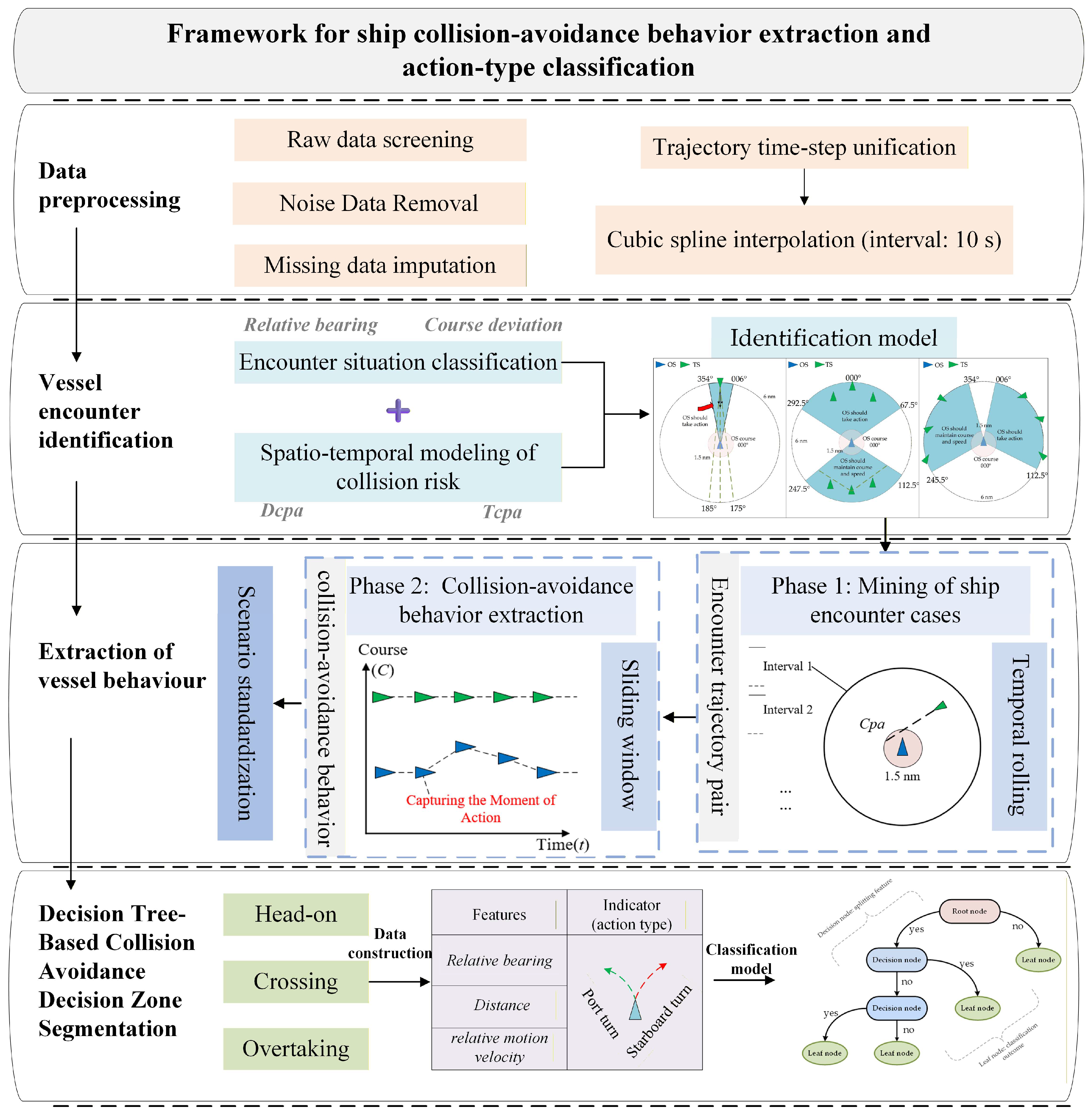
Figure 1. Framework of the research methodology.
Jmse 13 02240 g001
Figure 2. Ship encounter state identification model.
Jmse 13 02240 g002
Figure 3. Two-stage flowchart for extracting ship behavior.
Jmse 13 02240 g003
Figure 4. Sliding-window algorithm illustration.
Jmse 13 02240 g004
Figure 5. Ship encounter scenario standardization illumination.
Jmse 13 02240 g005
Figure 6. Ship action in three encounter scenarios illustration.
Jmse 13 02240 g006
Figure 7. Decision tree principle illustration.
Jmse 13 02240 g007
Figure 8. The data distribution map of the case water area.
Jmse 13 02240 g008
Figure 9. Polar distribution map of collision avoidance cases.
Jmse 13 02240 g009
Figure 10. Polar diagram of collision avoidance data for the three encounter situations.
Jmse 13 02240 g010
Figure 11. Three-dimensional collision avoidance data distribution for overtaking encounter configurations.
Jmse 13 02240 g011
Figure 12. Relative position diagram of own ship and target ship upon action-taking in a head-on encounter situation.
Jmse 13 02240 g012
Figure 13. Feature-based decision boundary for head-on.
Jmse 13 02240 g013
Figure 14. Actual actions under various bearings and ranges in head-on encounters illustration.
Jmse 13 02240 g014
Figure 15. The collision avoidance action decision-making azimuth map for head-on situation.
Jmse 13 02240 g015
Figure 16. Own ship collision avoidance action chart under crossing situations.
Jmse 13 02240 g016
Figure 17. Feature-based decision boundary for crossing.
Jmse 13 02240 g017
Figure 18. Collision avoidance action illustration in crossing encounters.
Jmse 13 02240 g018
Figure 19. The collision avoidance action decision-making azimuth map for crossing situation.
Jmse 13 02240 g019
Figure 20. Own ship collision avoidance action chart under overtaking situations.
Jmse 13 02240 g020
Figure 21. Feature-based decision boundary for overtaking.
Jmse 13 02240 g021
Figure 22. Full-sample sampling chart of the decision tree.
Jmse 13 02240 g022
Figure 23. Collision avoidance action illustration in overtaking encounters (overtaking ship).
Jmse 13 02240 g023
Figure 24. Collision avoidance action illustration in overtaking encounters (ship being overtaken).
Jmse 13 02240 g024
Figure 25. Ship collision avoidance action decision-making azimuth map.
Jmse 13 02240 g025
Table 1. Encounter situation classification parameters based on relative bearing and course difference.
SituationAOB: °Cdiff: °
Head-on[000°~006°]||[354°~360°][175°~185°]
Overtaking[0°~67.5°]||[292.5°~360°][0°~67.5°]||[292.5°~360°]
Crossing[6°~112.5°]||[247.5°~354°]Neither Head-on nor Overtaking
Table 2. Collision avoidance action sample subset for head-on encounter situations.
AOB: °S: nmActionAOB: °S: nmAction
3.94.446Starboard−3.43.435Starboard
2.44.827Starboard 2.43.685Port
−0.15.730Starboard 04.113Starboard
0.33.501Port3.05.662Starboard
1.34.012Starboard −1.94.418Starboard
−1.23.708Starboard 3.43.112Port
0.73.681Starboard −1.73.446Starboard
3.73.410Port−4.24.439Starboard
Table 3. Collision avoidance action sample subset for crossing encounter situations (give-way ship).
AOB: °S: nmActionAOB: °S: nmAction
33.73.015Starboard21.94.275Starboard
35.43.126Starboard73.94.060Starboard
46.75.542Starboard100.43.287Port
35.15.591Starboard13.43.231Port
82.35.847Starboard59.14.200Starboard
90.95.313Port67.63.769Starboard
16.34.551Starboard108.93.9Port
24.13.62Starboard82.42.761Starboard
102.64.54Port12.63.254Port
44.42.775Starboard59.63.9Starboard
Table 4. Collision avoidance action sample subset for crossing encounter situations (stand-on ship).
AOB: °S: nmActionAOB: °S: nmAction
299.51.714Starboard323.22.391Starboard
320.52.006Starboard342.02.194Starboard
339.81.782Starboard303.91.222Starboard
301.11.480Starboard333.52.215Port
300.02.412Starboard342.21.510Starboard
Table 5. Collision avoidance action sample subset for overtaking encounter situations (overtaking ship).
AOB: °S: nmr: °Action
352.21.919359.5Starboard
358.62.395359.9Starboard
8.61.52120.4Starboard
359.51.874336.4Port
4.33.1127.3Starboard
352.42.608348.6Port
8.41.65512.7Starboard
22.12.87317.9Port
356.32.476357.0Starboard
357.82.703357.7Port
350.21.9661.5Starboard
8.11.9714.6Port
39.82.97941.0Starboard
Table 6. Collision avoidance action sample subset for overtaking encounter situations (ship being overtaken).
AOB: °S: nmr: °Action
144.11.264139.5Port
238.61.204234.4Starboard
206.71.059214.3Port
216.51.122216.2Starboard
222.41.1218.6Starboard
Table 7. Collision avoidance action sample subset for overtaking encounter situations (overtaking ship—new feature).
AOB: °S: nmr-AOBAction
−7.62.1013.7Starboard
−3.22.6922.7Starboard
2.22.916−3.9Port
−1.42.3951.3Starboard
8.11.971−2.2Port
−4.282.2384.1Starboard
2.42.851−1.3Port
3.42.305−4.2Port
22.23.141.2Starboard
Table 8. Action decision-making azimuth map parameter description table.
Encounter StateEncounter
Situation
OS
Responsibility
Action
Conditions
Action
Patterns
A1-AHead-onEqual responsibilityS < 6Starboard
A2-AHead-onEqual responsibilityS < 4.6 and 0 < AOB < 6Port
A-C1OvertakingOvertaking shipS < 3.2 and r-AOB > 0/r-AOB < 0Starboard/Port
C2-AOvertakingShip being overtakenS < 1.3 and 180 < AOB < 247.5Starboard
C3-AOvertakingShip being overtakenS < 1.3 and 112.5 < AOB < 180Port
B1-A,B4CrossingGive-way shipS < 6 and AOB < 90.3Starboard
B2-A,B1CrossingGive-way shipS < 4.5 and 6 < AOB < 13.6Port
B3-A,B4CrossingGive-way shipS < 6 and 90.3 < AOB < 112.5Port
B4-A,BCrossingStand-on shipS < 2.5Starboard
OthersNo encounterMaintain course and speedOthersMaintain course and speed
Disclaimer/Publisher’s Note: The statements, opinions and data contained in all publications are solely those of the individual author(s) and contributor(s) and not of MDPI and/or the editor(s). MDPI and/or the editor(s) disclaim responsibility for any injury to people or property resulting from any ideas, methods, instructions or products referred to in the content.