Abstract
With the advancement of offshore wind energy toward deep-water floating systems, mooring and anchor foundations represent pivotal components whose load-bearing characteristics critically impact the safety and integrity of floating wind turbines. The dynamic responses of embedded suction anchor foundations for offshore wind mooring systems under cyclic and irregular mooring loads are investigated. A computationally efficient simplified methodology is developed, leveraging dynamic impedance theory and coordinate transformation techniques to derive stiffness and damping matrices at arbitrary padeye locations based on the assumption of a linearly elastic, homogeneous soil medium. The equations of motion are solved using both frequency-domain and time-domain approaches to predict responses under harmonic cyclic loading and irregular nonlinear mooring forces. The model demonstrates excellent self-consistency and achieves high-fidelity agreement with 3D finite element benchmarks at significantly reduced computational costs. Parametric analyses reveal that padeye elevation critically governs dynamic response, enabling rapid optimization of its placement to minimize displacements and enhance safety. Furthermore, scour depth significantly impacts foundation behavior, with severe scour conditions markedly increasing horizontal displacements and rocking rotations, thereby elevating structural failure risks. The proposed framework provides an efficient tool for preliminary design and risk assessment, highlighting scour mitigation as crucial for foundation integrity.
1. Introduction
Driven by carbon neutrality objectives, the offshore wind industry is advancing rapidly. With nearshore wind resources approaching saturation, deep offshore floating wind technology has become a focal point for future development [1]. Floating offshore wind turbines rely on seabed anchoring systems for station-keeping, among which suction anchors are widely adopted due to their precise positioning capability, high installation efficiency, and adaptability to varying water depths and diverse seabed soil conditions [2]. During operation, these anchors experience dynamic soil–structure interactions under mooring loads, posing dual risks of horizontal displacement failure and pull-out failure [3], thereby compromising the safety of entire floating wind systems. Consequently, assessing the dynamic behaviors of suction anchors when subjected to mooring loads is of paramount importance.
Extensive research has been conducted on the dynamic characteristics exhibited by embedded suction anchors in soil, employing both numerical and experimental methods. Experimental methods primarily include field tests [4,5] and model tests [6,7,8]. Ravichandran [4] conducted field tests on suction anchors with varying diameters and lengths, performing static and cyclic pullout tests to evaluate their extraction behaviors under diverse loading conditions. Chen [9] employed instrumented model caissons in a centrifuge testing program to assess the behaviors of sealed foundations under different loading conditions. The study, which encompassed normally consolidated, lightly overconsolidated, and sensitive clay deposits, specifically analyzed the changes in uplift capacity and external radial stress during sustained and cyclic loading. However, experimental methods require substantial funding and are time-intensive. Consequently, many researchers employ numerical approaches, predominantly using 3D finite element modeling [10,11,12] to effectively account for soil nonlinearity, soil–structure gaps, and interaction effects through appropriate soil constitutive models and interface properties. While 3D finite element modeling delivers accurate results, its high computational cost and low efficiency have motivated proposals for simplified dynamic response analysis methods.
Simplified dynamic analysis methods designed specifically for suction anchors remain scarce. Nevertheless, as suction anchors constitute a class of embedded rigid foundations, relevant research can be referred to. Gazetas et al. [13,14,15] and Dobry et al. [16,17] investigated multi-directional motions of arbitrarily shaped rigid foundations embedded in elastic half-spaces. Gazetas [18] and Gerolymos [19] compiled semi-analytical expressions for dynamic stiffness and damping at a foundation base center with a small (0~1) slenderness ratio (depth-to-diameter ratio) using boundary element methods and extensive published data, covering horizontal/vertical translation and rocking. Gadre and Dobry [20] validated these formulations via centrifuge testing. Zhong [21] extended applicability to slenderness ratio (1~4) by refining semi-analytical expressions through finite element modeling. However, the semi-analytical expressions compiled by Gazetas et al. [18] reference the foundation’s base center, whereas mooring forces on suction anchors act at the sidewall padeye—not the base center. To efficiently compute displacements at the padeye (mooring connection point), this study will employ a robust methodology to derive the semi-analytical expressions for dynamic stiffness and damping in reference to the padeye location.
Moreover, in complex marine environments, scour is highly prevalent where seabed soil surrounding foundations erode under combined wave–current actions. Existing research confirms that soil–foundation dynamic characteristics are significantly altered by scour [22,23], consequently modifying the dynamic responses of suction anchors under loading [24]. Hu et al. [25] investigated local scour around caisson suction anchors under random waves, analyzing scour evolution processes and mechanisms while predicting equilibrium scour depths. Zhang et al. [26] developed an analytical framework to assess pullout capacity during trench–scour development, revealing pronounced impacts of both trenching and scouring effects on anchor performance.
This study conducts numerical analysis on the mooring load-bearing behaviors of offshore wind suction anchor foundations. To facilitate swift and effective initial design, a streamlined dynamic analysis approach is introduced. Based on the assumption of a linearly elastic, homogeneous soil medium, leveraging dynamic impedance theory and coordinate transformation techniques, stiffness and damping matrices at arbitrary padeye locations are derived. The equations of motion for embedded suction anchors are established, with frequency-domain and time-domain solutions applied to resolve dynamic responses under both harmonic cyclic loading and irregular nonlinear mooring forces. This method achieves a balance between acceptable accuracy and computational speed. The complete framework is outlined in Section 2. Validation against 3D finite element results in Section 3 confirms the model’s reliability. Section 4 presents selected mooring load cases and demonstrates dynamic responses at varying padeye elevations and scour depths. Concluding remarks are synthesized in Section 5.
2. Mathematical Formulation
Consider a fully embedded suction anchor foundation interacting with seabed soil under mooring forces. Assuming complete consolidation of the internal soil, the suction anchor and its enclosed soil are simplified and analyzed as an integrated rigid body. For modeling purposes, a 2D Cartesian coordinate system Oxz is established, as shown in Figure 1, with its origin at the center of the anchor base. The x-axis extends horizontally rightward along the base, while the z-axis extends vertically upward along the central axis. The suction anchor has a height h, embedment depth d, and diameter B. Mooring forces are applied at the padeye on the sidewall. The soil is modeled as a homogeneous, elastic half-space with shear modulus , Poisson’s ratio , and density . Full interfacial contact between the suction anchor and surrounding soil is maintained throughout the analysis.
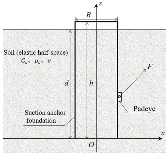
Figure 1.
Schematic diagram of the interaction of the embedded suction anchor foundation with seabed soil.
2.1. Suction Anchor Foundation Motion Equation
Under mooring forces, the motion of a suction anchor foundation primarily comprises three modes: horizontal displacement, vertical displacement, and rotation. Excessive horizontal displacement may trigger soil punching failure, while significant vertical displacement can lead to anchor pull-out. Defining point as the padeye attachment point, the dynamic response equation for is expressed as follows:
is the mass matrix, is the damping matrix and is the stiffness matrix of the suction anchor foundation. m is the sum of the mass of the suction anchor and the internal soil, with the soil mass accounting for the majority. The specific calculation methods for the damping matrix and stiffness matrix elements are presented in Section 2.2. is the displacement at , which includes horizontal displacement , vertical displacement , and rotation angle . The dots above the variable indicate its time derivative. Therefore, and are the velocity and acceleration of the padeye attachment point of the suction anchor , respectively. is the mooring force, which includes the horizontal component , vertical component and moment . and represent the horizontal and vertical coordinates at the center of mass of the anchor–soil structure, respectively. approximately represents the moment of inertia of the anchor-soil structure at point , and it is calculated as follows:
2.2. Suction Anchor Foundation Stiffness and Damping Analysis
2.2.1. Embedded Foundation Impedance Functions
Treat the system composed of the suction anchor foundation and the internal soil as an embedded rigid foundation; the impedance functions for such foundations on a half-space [18,19,21] are utilized to formulate the stiffness matrix and damping matrix at the center of the suction anchor’s bottom. and contain the following elements:
The horizontal dynamic stiffness and damping values [18,20] can be calculated as follows:
where is the horizontal static stiffness of the surface-founded foundation, is the horizontal embedment coefficient, is the horizontal dynamic stiffness factor of the embedded foundation, is the shear wave velocity of soil, is the ‘Lysmer’s analog’ velocity, and is the dimensionless frequency.
The vertical dynamic stiffness and damping values [18] can be represented as follows:
where is the vertical static stiffness of the surface-founded foundation, is the vertical embedment coefficient, and is the vertical dynamic stiffness factor of the embedded foundation.
The rocking dynamic stiffness and damping values [18,19,21] can be calculated as follows:
where is the rocking static stiffness of the surface-founded foundation, and are intermediate variables, is the rocking embedment coefficient, and is the rocking dynamic stiffness factor of the embedded foundation.
The coupled horizontal-rocking dynamic stiffness and damping factors for the center of the embedded suction anchors are determined [18,19,21] by the following relationships:
2.2.2. Dynamic Stiffness and Damping Matrices at the Padeye
During operation, suction anchor foundations are subjected to mooring forces transmitted from the floating wind turbine platform. These forces act at the padeye attachment point on the sidewall rather than at the foundation’s bottom center. Consequently, displacement calculation at the load application point (i.e., the padeye location) under mooring forces constitutes a critical research focus. This study establishes dynamic stiffness and damping matrices at arbitrary surface points (including the padeye) through coordinate transformation of the base–center dynamic stiffness and damping derived in Section 2.2.1, thus enabling rapid determination of the anchor’s dynamic response. The detailed derivation process is presented as follows.
For the convenience of derivation, the dynamic stiffness matrix at the anchor base center is first expanded to a 6 × 6 matrix and partitioned as follows:
Consequently, the relationship between soil reaction forces, displacements, and the stiffness matrix at the suction anchor base center is formulated as follows:
which is equivalent to
where and represent the displacement and rotation angle at the center of the bottom of the suction anchor foundation , respectively. and denote the soil reaction force and moment at , respectively.
When transforming the coordinate system origin from point to padeye point on the suction anchor, the displacements and rotations between these points obey the following kinematic relationships:
where and are the displacements and rotations at the point , respectively. is a transformation matrix in the following form:
The soil reaction force and moment at and obey the following relationship:
where and denote the soil reaction force and moment at , respectively.
Substituting Equations (27)–(30) into Equations (32) and (33), we can obtain the following:
So, the transformed dynamic stiffness matrix at padeye point on the suction anchor is given by the following:
Substituting Equation (25) into Equation (36) and reducing to two-dimensional degrees of freedom, the dynamic stiffness matrix at is given by the following:
Similarly, the corresponding damping matrix at padeye point is as follows:
2.3. Dynamic Response Analysis Method
2.3.1. Calculation Method in the Frequency Domain
For the dynamic response Equation (1) of the suction anchor foundation, when the applied force F is harmonic, the suction anchor foundation undergoes harmonic motion. Under these conditions, the time-harmonic term can be extracted for frequency-domain analysis as follows:
where is the circular frequency. Consequently, the dynamic response equation in the frequency domain for the suction anchor under harmonic mooring forces is expressed as follows:
Then the harmonic motion of the suction anchor foundation can be calculated in the frequency domain.
2.3.2. Time Marching Method in the Time Domain
Under the actual operating conditions of suction anchors, the applied load F is typically non-harmonic and manifests as an irregular nonlinear force, necessitating time-domain solutions via time-stepping schemes.
Assume zero initial displacement and velocity of the suction anchor foundation. After determining the values of mass, stiffness, and the damping matrix in Equation (1), the acceleration at the padeye of the suction anchor at the current time step under mooring forces can be obtained. Then a fourth-order Runge–Kutta (RK4) method is employed to derive the displacement and velocity at at the next time step. The specific steps are as follows.
Given the displacement and velocity at at time t, the acceleration is determined by solving Equation (1). This relationship is formally expressed as follows:
Furthermore, the displacement and velocity at satisfy Newton’s equations of motion. Thus, these quantities at the subsequent time step () are computed via the fourth-order Runge–Kutta (RK4) method:
where
The numerical computation procedure is structured as follows: given the known displacement and velocity at at time t, the value of is computed via Equation (43). This acceleration value then drives the iterative update to determine the displacement and velocity at the subsequent time step (). The recursive integration cycle yields full temporal evolution of the dynamic states. In the end, the displacement and velocity at at time are resolved through Equations (44) and (45).
To ensure numerical stability, a time step of T/100 is adopted (where T denotes the mooring force period). Additionally, a ramp function applied at simulation initialization enhances stability and accelerates convergence to steady-state conditions. Following Baudic [27], this ramp function is defined as follows:
3. Validation
To verify the reliability of our model in simulating the dynamic responses of embedded suction anchors in homogeneous elastic soil, we established a new finite element numerical model for soil–suction anchor interactions using the software Abaqus (Abaqus 2024), as shown in the Figure 2. The high-fidelity Abaqus model, which explicitly simulates the anchor’s wall thickness, open bottom, and the distinct soil bodies inside and outside the anchor, served as the benchmark. It was compared against the proposed simplified model, which employs the simplification of treating the anchor and interior soil as an integrated rigid body.
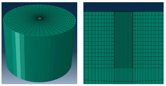
Figure 2.
Schematic of the finite element model for suction anchor–soil interactions.
In the Abaqus model, the material of soil is homogeneous linear elastic. The suction anchor foundation is idealized as a rigid structure fully embedded at the top center of the soil domain. The suction anchor foundation is open at the bottom and is fully filled with soil. The soil–structure interface maintains fully tied contact without separation. The bottom surface of the soil model is assigned a fully fixed constraint, while its sides are horizontally restrained. Infinite elements are applied to the outer boundaries of the soil model to eliminate wave reflections, thereby simulating an elastic half-space. The model parameters are shown in Table 1.

Table 1.
Model parameters in Section 3 (Validation).
A mesh convergence study was conducted to ensure the accuracy of the numerical results while maintaining computational efficiency. Three mesh configurations with varying levels of refinement (Mesh A, Mesh B, and Mesh C) were generated, with their specific information summarized in Table 2. The horizontal displacement at the padeye under a 10 Hz dynamic load was selected as the key metric for comparison. As illustrated in Figure 3, the result from the coarsest mesh (Mesh A) showed a notable deviation. In contrast, the results from the medium and finest meshes (Mesh B and Mesh C) were in close agreement. This indicated that the solution converged with Mesh B. Therefore, Mesh B was adopted for all subsequent simulations in this study, as it provided an optimal balance between numerical accuracy and computational cost. In addition, an explicit dynamics analysis was employed, with the time increment being automatically controlled by the solver to maintain stability.

Table 2.
Quantities of elements in varied grid systems.
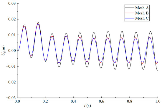
Figure 3.
Convergence of the horizontal displacement at the padeye of the suction anchor with different meshes.
Figure 4 compares horizontal and vertical displacements at the load application point when forces act at the anchor sidewall padeye. The results demonstrate good agreement between the proposed models and finite element simulations. Additionally, computational times are recorded on an Intel(R) Core(TM) i7-14700F processor: the finite element model requires approximately 10 min, the proposed time-domain model completes calculations in under 3 s, and the frequency-domain model requires less than 1 s. This confirms the achievement of a significantly higher computational efficiency while maintaining acceptable accuracy.
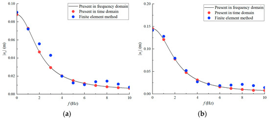
Figure 4.
Displacement comparison at the padeye location on the suction anchor sidewall under dynamic loading: (a) horizontal displacement and (b) vertical displacement .
4. Results and Discussion
The anchor parameters are based on the stocky suction anchors in the Timor Sea (Randolph and Gourvenec [28]). For a suction anchor foundation embedded in homogeneous elastic seabed soil, the model parameters are shown in Table 3.

Table 3.
Model parameters in Section 4 (Results and Discussion).
This study focused on investigating the effects of padeye location and scour conditions on the dynamic response of the suction anchor foundation. To elucidate fundamental mechanisms, the regular monochromatic harmonic mooring force was initially applied for simulation. For realistic characterization of dynamic performance under actual sea conditions, where anchors experience irregular nonlinear mooring loads transmitted from superstructures, subsequent simulations employed irregular nonlinear mooring forces.
4.1. Loads on the Suction Anchor
4.1.1. Harmonic Force
To investigate fundamental response mechanisms, harmonic mooring loads of the following form were selected for application on the suction anchor:
where , is the ramp function, defined by Equation (41). Figure 5 displays the time-history curves of horizontal and vertical components for harmonic loads at frequencies of 2 Hz and 4 Hz.
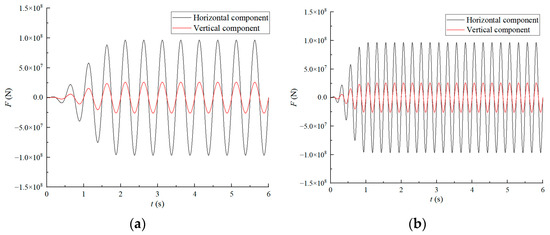
Figure 5.
Time-history curves of horizontal and vertical components for harmonic loads at (a) f = 2 Hz and (b) f = 4 Hz.
For dynamic response analysis of the suction anchor under harmonic forces, the frequency-domain method (Section 2.3.1) was employed.
4.1.2. Irregular Nonlinear Forces
To further investigate the dynamic responses of suction anchors under near-actual operating conditions, this study additionally employed an irregular nonlinear mooring force with custom spectral characteristics. The Fourier spectrum of this mooring force, along with time-history curves of its horizontal and vertical components, are presented in Figure 6. The peak spectral frequency was 1.5 Hz.
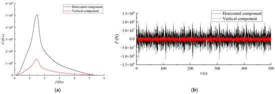
Figure 6.
Schematic illustration of the irregular mooring forces in the horizontal and vertical directions: (a) Fourier spectrum of force and (b) time-history curves of force.
For dynamic response analysis of the suction anchor under irregular nonlinear mooring force, the time-domain method (Section 2.3.2) is employed. It should be noted that the stiffness and damping matrices in the equation of motion (1) are frequency-dependent. This presents a fundamental dilemma for irregular load analysis, as the excitation encompasses a spectrum of frequencies, preventing the definition of a unique system matrix. To overcome this and render the problem tractable, this study adopts the following simplification: stiffness and damping matrices corresponding to the spectral peak frequency are utilized as constant matrices during irregular force application. This approximation is justified because the input energy of the considered irregular load is predominantly concentrated around its peak frequency, making the system’s response at this dominant frequency most critical. Consequently, while this approach offers computational efficiency and a solvable framework, the results should be interpreted as an approximation, particularly suitable for comparative assessments under similar loading conditions.
4.2. Effect of Padeye Location
4.2.1. Analysis with Harmonic Force
This section examines the dynamic responses of the suction anchor foundation under harmonic mooring forces by varying the vertical padeye position . Figure 7 presents horizontal and vertical displacements and rocking rotations for six padeye elevations ( = h, 0.8h, 0.6h, 0.4h, 0.2h, and 0) across different loading frequencies. The horizontal displacement decreases with increasing excitation frequency. As the padeye position is gradually raised from the base, the horizontal displacement initially decreases and then increases. At = 0.4h, the horizontal response remains consistently the smallest across all frequencies. When does not exceed 0.6h, the vertical displacement gradually decreases with increasing frequency and as the padeye position is raised. When exceeds 0.6h, the trend of vertical displacement with frequency becomes more complex, which may be attributed to the coupling between vertical motion and rotation. Rocking rotation initially increases and then decreases with increasing frequency. As the padeye position is raised, the rotation first decreases and then increases, while the = 0.4h configuration achieves the lowest rotation magnitudes throughout the frequency spectrum.
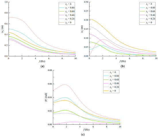
Figure 7.
Variations in displacements at the padeye with loading frequency at different padeye elevations: (a) horizontal displacement, (b) vertical displacement, and (c) rocking rotation.
Since mooring forces on suction anchors are predominantly horizontal, and horizontal displacement constitutes the primary failure mode, padeye positioning should optimize resistance against such failure. Figure 8 illustrates the variation in horizontal displacement at the padeye with normalized vertical coordinate () under 1.5 Hz excitation. The results demonstrate that horizontal displacement initially decreases and then increases with increasing padeye elevation, with the lowest response occurring at . It should be emphasized that the present study is specifically focused on optimizing the padeye location to minimize dynamic displacement. In practical design, this factor must be integrated with other key engineering requirements to achieve a comprehensive optimal solution for the padeye location.
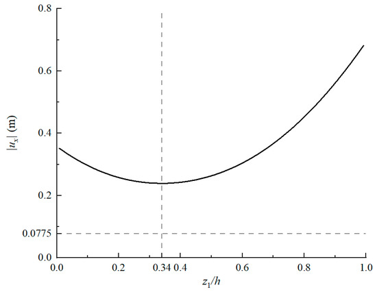
Figure 8.
Horizontal displacement at the padeye of the suction anchor foundation varying with the vertical height of the padeye when the loading frequency is 1.5 Hz.
4.2.2. Analysis with Irregular Nonlinear Forces
This section investigates the dynamic responses of suction anchors under irregular nonlinear mooring forces to simulate operational conditions. Based on previous findings regarding the influence of padeye elevation, analyses are conducted for two configurations: and the horizontal displacement-minimizing .
Figure 9 presents time-history curves of horizontal displacement, vertical displacement, and rocking rotation for both cases under irregular loading. Horizontal displacement records reveal substantially reduced amplitudes in the case compared to the case. Rocking rotations demonstrate consistent and significant reductions across the entire time-history curve at the optimal elevation. While vertical displacements show marginally higher magnitudes at , their overall variations remain constrained, which is manifested as their volatility being lower than that of the horizontal component, and the peak value will not exceed 20% of the horizontal displacement.
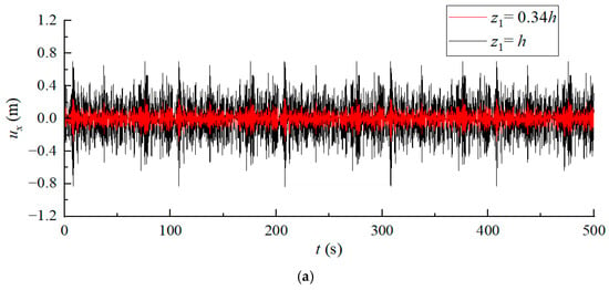
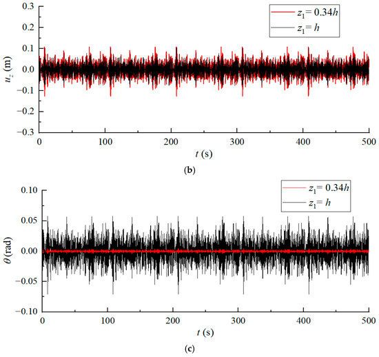
Figure 9.
Time-history curves of displacements at the padeye at different padeye elevations: (a) horizontal displacement, (b) vertical displacement, and (c) rocking rotation.
4.3. Effect of the Scour Depth
In complex wave–current environments, soil at the mudline surrounding suction anchors may erode due to scouring. To investigate scour depth effects on dynamic behavior, four cases are analyzed: , 0.1h, 0.3h, 0.5h, with padeye elevation fixed at the horizontal displacement-minimizing identified in Section 4.2.1. In this study, the effect of scour on the anchor’s behavior is simulated by a uniform reduction in embedment depth. It is acknowledged that this approach is a simplification that does not replicate the true geometry of a scour hole (slope and scour breadth). However, it serves as a practical and efficient tool for preliminary design assessment.
4.3.1. Analysis with Harmonic Force
Figure 10 reveals distinct response patterns: at mild scour (), horizontal displacement and rocking rotation show negligible changes, but deeper scour significantly amplifies these responses, particularly in low-frequency regimes where horizontal displacement increases by 180~300% and rotation peaks surge 30 times at . Vertical displacement remains relatively stable across scour levels, though the trend of vertical displacement with frequency becomes complex at , which likely stems from intensified vertical displacement–rocking coupling effects. The significant increases in horizontal and rotational displacements due to scouring indicate a severe compromise of system stability, posing a direct threat to the reliability of the anchoring function and potentially leading to bearing capacity failure.
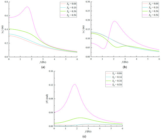
Figure 10.
Variations in displacements at the padeye with loading frequency at different scour depths: (a) horizontal displacement, (b) vertical displacement, and (c) rocking rotation.
4.3.2. Analysis with Irregular Nonlinear Forces
Figure 11 presents the time-history responses of the suction anchor under irregular nonlinear loading at scour depths of 0.0h and 0.5h, revealing markedly amplified horizontal displacements and rocking rotations under severe scour conditions, which indicates structurally critical performance degradation. As evidenced in the results, scour effects most pronouncedly amplify rocking rotations of the suction anchor foundation, followed by horizontal displacements. Critically, these two response modes, namely, the larger oscillation and the horizontal movement, represent the predominant failure mechanisms observed in practice, confirming that scour poses a substantial threat to structural safety.
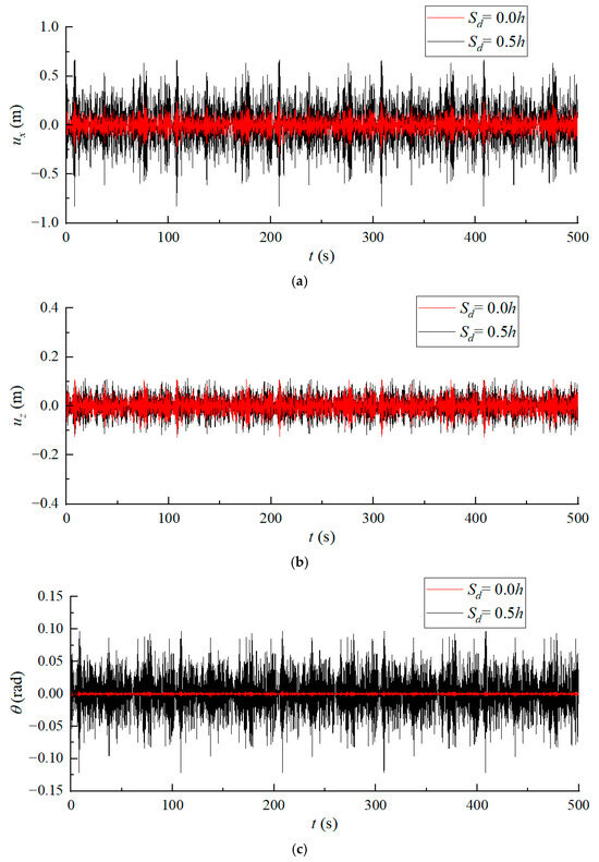
Figure 11.
Time-history curves of displacements at the padeye at different scour depths: (a) horizontal displacement, (b) vertical displacement, and (c) rocking rotation.
The simulation of scour by reducing embedment depth, while computationally efficient, does not capture the altered soil failure mechanism or the loss of passive resistance caused by a realistic scour pit geometry. Consequently, the model might not fully represent the degradation in bearing capacity due to scour.
5. Conclusions
This study investigates the dynamic response characteristics of embedded suction anchor foundations under mooring forces. Initially, the equations of motion for anchors in soil were established. Subsequently, based on the assumption of a linearly elastic and homogeneous soil medium, dynamic stiffness and damping formulations for embedded foundations were derived, and coordinate transformation techniques were employed to obtain impedance matrices at arbitrary padeye locations. Frequency-domain and time-domain methods were then applied to resolve horizontal, vertical, and rocking motions under both harmonic cyclic loading and irregular nonlinear mooring forces. Parametric analyses examined padeye elevation and scour depth effects on dynamic behavior. The key conclusions were as follows:
- (1)
- Validation against a detailed finite element model confirms that the proposed simplified model, based on the integrated rigid body assumption, achieves a favorable balance between predictive accuracy and computational cost. This demonstrates its reliability and practical value for dynamic analysis.
- (2)
- Padeye elevation critically governs dynamic response. The proposed methodology enables rapid optimization of padeye placement to minimize response amplitudes, enhancing design efficiency and structural safety.
- (3)
- The scouring depth has a significant impact on the dynamic response characteristics of the suction anchor foundation. Severe scour will significantly increase horizontal displacements and rocking rotations, which directly elevates structural failure risks.
Notwithstanding its computational efficiency and value for preliminary design, this study has certain limitations that warrant attention. The adopted linear soil model, while providing satisfactory accuracy under conventional working conditions with small-strain levels, may exhibit lower predictive accuracy under extreme conditions such as earthquakes, as it fails to capture soil nonlinearities, including strain-dependent variations in shear modulus and damping. Future research will focus on enhancing the model’s predictive capability by implementing the Hardin–Drnevich model (Hardin and Drnevich [29], Tu et al. [30]) within the time-domain framework to enable real-time updates of the shear modulus and damping ratio based on dynamic strain levels. Experimental validation is also planned to verify and refine the proposed methodology, thereby extending its applicability to a broader range of geotechnical design problems.
Author Contributions
Conceptualization, S.L., Y.L. and F.L.; investigation, S.L.; methodology, S.L.; supervision, Y.L. and F.L.; validation, S.L.; writing—original draft, S.L.; writing—review and editing, S.L., Y.L. and F.L. All authors have read and agreed to the published version of the manuscript.
Funding
This research was supported by the Postdoctoral Fund Project of Shanghai Investigation, Design & Research Institute Co., Ltd. (Grant No. 2025FD(831)-001).
Data Availability Statement
The original contributions presented in the study are included in the article.
Conflicts of Interest
Authors Shuang Liang and Yifeng Lin were employed by Shanghai Investigation, Design and Research Institute Co., Ltd. The remaining author declares that the research was conducted in the absence of any commercial or financial relationships that could be construed as a potential conflict of interest. The authors declare that this study received funding from Shanghai Investigation, Design & Research Institute Co., Ltd. The funder was not involved in the study design, collection, analysis, interpretation of data, the writing of this article or the decision to submit it for publication.
References
- Musial, W.S.B.; Jonkman, J.; Sclavounos, P. Engineering challenges for floating offshore wind turbines. In Proceedings of the 2005 Copenhagen Offshore Wind Conference, Copenhagen, Denmark, 26–28 October 2005. [Google Scholar]
- Rui, S.J.; Zhou, Z.F.; Gao, Z.; Jostad, H.P.; Wang, L.Z.; Xu, H.; Guo, Z. A review on mooring lines and anchors of floating marine structures. Renew. Sustain. Energy Rev. 2024, 199, 114547. [Google Scholar] [CrossRef]
- Wang, J.H.; Li, S.Z. Pseudo static finite element analysis of bearing capacity of suction anchor subjected to cyclic loads in soft clay. Chin. J. Geotech. Eng. 2013, 35, 1403–1414. (In Chinese) [Google Scholar]
- Ravichandran, V.; Maji, V.B.; Gandhi, S.R. Field testing of suction anchors for mooring applications. Indian Geotech. J. 2015, 45, 267–277. [Google Scholar] [CrossRef]
- Cho, Y.; Lee, T.H.; Park, J.B.; Kwag, D.J.; Chung, E.S. Field validation of suction pile installation in clay. In Proceedings of the Twelfth International Offshore and Polar Engineering Conference, Kitakyushu, Japan, 26–31 May 2002; pp. 815–819. [Google Scholar]
- Narasimha Rao, S.; Ravi, R.; Siva Prasad, B. Pullout behavior of suction anchors in soft marine clays. Mar. Georesour. Geotechnol. 1997, 15, 95–114. [Google Scholar]
- Byrne, B.W.; Houlsby, G.T. Experimental investigations of the cyclic response of suction caissons in sand. In Proceedings of the Offshore Technology Conference, Houston, TX, USA, 1–4 May 2000. [Google Scholar]
- Yang, Q.; Pan, G.L.; Liu, H.J.; Wang, Q.D. Bearing capacity of offshore umbrella suction anchor foundation in silty soil under varying loading modes. Mar. Georesour. Geotechnol. 2018, 36, 781–794. [Google Scholar] [CrossRef]
- Chen, W.; Randolph, M.F. Uplift capacity of suction caissons under sustained and cyclic loading in soft clay. J. Geotech. Geoenviron. 2007, 133, 1352–1363. [Google Scholar] [CrossRef]
- Liu, R.; Wang, L.; Ding, H.Y. Failure envelopes of large-diameter shallow buried bucket foundation in undrained saturated soft clay under combined loading conditions. Chin. J. Geotech. Eng. 2014, 36, 146–154. [Google Scholar]
- Shen, K.; Wang, L.; Guo, Z.; Jeng, D.S. Numerical investigations on pore-pressure response of suction anchors under cyclic tensile loadings. Eng. Geol. 2016, 227, 108–120. [Google Scholar] [CrossRef]
- Zhou, M.; Hossain, M.S.; Hu, Y.; Liu, H. Installation of stiffened caissons in non- homogeneous clays. J. Geotech. Geoenviron. 2016, 142, 04015079. [Google Scholar] [CrossRef]
- Gazetas, G.; Dobry, R.; Tassoulas, J.L. Vertical response of arbitrarily shaped embedded foundations. J. Geotech. Eng. ASCE 1985, 111, 750–771. [Google Scholar] [CrossRef]
- Gazetas, G.; Tassoulas, J. Horizontal stiffness of arbitrarily shaped embedded foundations. J. Geotech. Eng. ASCE 1987, 113, 440–457. [Google Scholar] [CrossRef]
- Gazetas, G.; Tassoulas, J.L. Horizontal damping of arbitrarily shaped embedded foundations. J. Geotech. Eng. ASCE 1987, 113, 458–475. [Google Scholar] [CrossRef]
- Dobry, R.; Gazetas, G. Dynamic stiffness and damping of foundations by simple methods. In Vibration Problems in Geotechnical Engineering; Gazetas, G., Selig, G., Eds.; ASCE: New York, NY, USA, 1985; pp. 77–107. [Google Scholar]
- Dobry, R.; Gazetas, G. Dynamic response of arbitrarily shaped foundations. J. Geotech. Eng. ASCE 1986, 112, 109–135. [Google Scholar] [CrossRef]
- Gazetas, G. Formulas and charts for impedances of surface and embedded foundations. J. Geotech. Eng. ASCE 1991, 117, 1363–1381. [Google Scholar] [CrossRef]
- Gerolymos, N.; Gazetas, G. Winkler model for lateral response of rigid caisson foundations in linear soil. Soil Dyn. Earthq. Eng. 2006, 26, 347–361. [Google Scholar] [CrossRef]
- Gadre, A.; Dobry, R. Lateral cyclic loading centrifuge tests on square embedded footing. J. Geotech. Geoenviron. Eng. ASCE 1998, 124, 1128–1138. [Google Scholar] [CrossRef]
- Zhong, R. Dynamic Analyses and Centrifuge Tests of Caisson-Piles Foundations. Ph.D. Thesis, Tongji University, Shanghai, China, 2013. [Google Scholar]
- Liang, F.; Zhang, H.; Huang, M. Influence of flood-induced scour on dynamic impedances of pile groups considering the stress history of undrained soft clay. Soil Dyn. Earthq. Eng. 2017, 96, 76–88. [Google Scholar] [CrossRef]
- Zhang, H.; Liang, F.; Zheng, H. Dynamic impedance of monopiles for offshore wind turbines considering scour-hole dimensions. Appl. Ocean. Res. 2021, 107, 102493. [Google Scholar] [CrossRef]
- Liu, H.J.; Pan, G.L.; Cao, L. Scour characteristics of umbrella suction anchor foundation under single current. Period. Ocean. Univ. China 2021, 51, 117–124. [Google Scholar]
- Hu, R.; Liu, H.; Leng, H.; Yu, P.; Wang, X. Scour Characteristics and Equilibrium Scour Depth Prediction around Umbrella Suction Anchor Foundation under Random Waves. J. Mar. Sci. Eng. 2021, 9, 886. [Google Scholar] [CrossRef]
- Zhang, M.H.; Yin, Z.Y.; Fu, Y. Pull-out capacity and failure mechanism of suction anchors in clay considering trench configuration and local scour effects. Eng. Geol. 2025, 347, 107942. [Google Scholar] [CrossRef]
- Baudic, S.F.; Williams, A.N.; Kareem, A. A two-dimensional numerical wave flume—Part 1: Nonlinear wave generation, propagation and absorption. ASME J. Offsh. Mech. Arct. Eng. 2001, 123, 70–75. [Google Scholar] [CrossRef]
- Randolph, M.; Gourvenec, M.R.S. Offshore Geotechnical Engineering; CRC Press: Boca Raton, FL, USA, 2011. [Google Scholar]
- Hardin, B.O.; Drnevich, V.P. Shear modulus and damping in soils: Design equations and curves. J. Soil Mech. Found. Div. 1972, 98, 667–692. [Google Scholar] [CrossRef]
- Tu, W.B.; Huang, M.S.; Gu, X.Q. Dynamic behavior of laterally loaded caisson foundations based on different cushion types: An experimental and theoretical study. J. Zhejiang Univ. Sci. A 2020, 21, 565–579. [Google Scholar] [CrossRef]
Disclaimer/Publisher’s Note: The statements, opinions and data contained in all publications are solely those of the individual author(s) and contributor(s) and not of MDPI and/or the editor(s). MDPI and/or the editor(s) disclaim responsibility for any injury to people or property resulting from any ideas, methods, instructions or products referred to in the content. |
© 2025 by the authors. Licensee MDPI, Basel, Switzerland. This article is an open access article distributed under the terms and conditions of the Creative Commons Attribution (CC BY) license (https://creativecommons.org/licenses/by/4.0/).