Abstract
Numerical simulation of the welding process is critical for predicting and controlling structural deformation. Previous numerical studies have predominantly focused on investigating the welding deformation of simple structures. However, actual engineering structures in naval architecture, aerospace, and construction applications exhibit significantly greater complexity. This study develops a finite element–based numerical approach to analyze the welding deformation in a stiffened curved panel–cylindrical shell hybrid structure. The connection between the stiffened curved panel and the cylindrical shell is achieved through a multi-pass welding procedure. The welding efficiency is enhanced through a segmented moving heat source model, which offers measurable practical benefits in engineering implementation. Furthermore, two useful strategies are proposed to mitigate the welding deformation, namely the utilization of welding sequence optimization and the applications of mechanical constraints. The results demonstrate an over 20% reduction in the out-of-plane deformation of the stiffened curved panel and more than 30% in the radial deformation of the cylindrical shell. It is indicated that the presented numerical approach can serve as a practical tool for the welding process optimization of complex welded structures.
1. Introduction
Stiffened curved panels and cylindrical shells are the critical load-bearing components in submarine hulls, offshore platforms, and aerospace structures. These structural members are generally connected by using welding technology. The welding process inevitably induces structural deformation and residual stress due to localized non-uniform thermal expansion and contraction of the metal adjacent to the weld in heating and cooling phases [1]. These imperfections may degrade the mechanical properties, such as fatigue life and buckling resistance. In addition, severe welding deformation adversely affects both the visual appearance and assembly accuracy of the components [2]. For complex hybrid structures, experimental testing of multi-pass welding processes is economically prohibitive due to the exorbitant time and financial expenditures. Fortunately, numerical simulation of welding emerges as a viable alternative, providing a cost-efficient approach for predicting structural deformations. By implementing thermo-mechanical simulations prior to actual construction, manufacturers are able to identify the distortion severity and refine the welding procedure to minimize rework.
Over the past decades, numerical simulation has significantly enhanced our ability to understand and predict welding-induced structural deformation. Choobi et al. [3] applied a thermo-elasto-plastic finite element method (FEM) to calculate the welding deformation in a 2 mm thick 304 stainless steel butt joint. Their results showed good agreement between the predicted angular distortion and experimental measurements. Based on the ABAQUS software platform, Long et al. [4] developed a thermo-elasto-plastic FEM to predict the mechanical responses of thin-plate butt joints induced by welding. Murakawa et al. [5] and Nishikawa et al. [6] developed an iterative substructure method for thick-plate welding simulation by dividing the finite element model into plastic/elastic zones. During iterative calculations, only the plastic zone is processed, thereby significantly enhancing computational efficiency in numerical simulation. In addition, Zhou et al. [7] investigated the welding-induced radial deformation in ring-stiffened cylindrical shells through an integrated computational approach.
The thermo-elasto-plastic FEM can accurately simulate the welded joints but faces challenges in large-scale structures due to the high computational costs. To overcome these limitations, Chen et al. [8] proposed a shell–solid mixed modeling approach, while Perić et al. [9] demonstrated a shell–solid hybrid element for modeling T-joints, both achieving experimental validation with improved computational efficiency. Zhou et al. [10] developed a thermo-elasto-plastic FEM incorporating an iterative substructure method and multi-core parallel computing technology. This method enables addressing the strong nonlinearities inherent in welding mechanical responses while considerably enhancing the computational efficiency. For thermo-elasto-plastic FEM, another approach to improve the computational efficiency is to adopt simplified heat source models. Kiyoshima et al. [11] successfully improved the efficiency by replacing the Gaussian heat source with segmented volumetric heat flux.
Control of welding-induced deformation constitutes a fundamental consideration in structural fabrication processes. Current methods primarily focus on optimizing welding sequences and applying mechanical constraints, both widely proven in industry applications. Fu et al. [12] reported that clamp–release boundary conditions significantly reduce the deformation in T-joints, whereas Desai and Bag [13] reported higher residual stress near constrained zones in micro-spot laser welds compared to free-state conditions. Combining experimental and numerical analysis, Wang et al. [14] established that web-first welding can minimize the distortion in H-type Q345 steel butt joints. Wang et al. [15] proposed that the preset reverse deformation, optimized welding sequences, and external constraints can effectively reduce transverse bending and angular distortion in I-section cantilever beams. Zhang et al. [16] proved that edge constraints and preset reverse deformation can reduce angular distortion yet marginally affect residual stress in multi-pass spherical joints. Yi et al. [17] also showed significant reduction in welding deformation using edge constraints and rigid cylindrical supports in propeller base structures. In addition to the aforementioned deformation control measures, scholars have also investigated the effectiveness of other approaches, such as the reverse pre-deformation method [16,18] and post-weld heat treatment [19], in reducing the welding distortion.
The literature reveals a predominant focus on welding deformation in simple structures, with limited attention to multi-pass welded complex assemblies. To this end, this paper investigates the prediction and control of welding deformation in a stiffened curved panel–cylindrical shell hybrid structure. The complete welding process is simulated using the sequential coupled thermo-elasto-plastic finite element method. The shell–solid mixed modeling approach and the segmented moving heat source model are employed to accelerate the multi-pass welding simulation. Furthermore, the effectiveness of optimized weld pass sequences and support structures in controlling welding deformation is investigated. Comparative analysis of the two constraint schemes revealed significant deformation reduction through structural optimization.
2. Structural Arrangement and Welding Procedure
The investigated structure is shown in Figure 1. This structure integrates three key components: a curved base plate measuring 5000 mm in length, 4000 mm in width, and 80 mm in thickness; a cylindrical shell with 2500 mm diameter, 1800 mm axial length, and 60 mm wall thickness; and an array of orthogonal stiffeners with 142 mm height welded to the curved panel. Note that the curved panel and longitudinal stiffeners maintain longitudinal curvature while remaining straight in the transverse direction. In addition, the cylindrical shell penetrates through the central region of the stiffened curved panel, with its axis oriented at an angle relative to the surface normal at the panel’s geometric center. The three components exhibit fundamentally different geometries and deliver complementary structural performance characteristics. Their manufacturing process is much more complex compared to conventional simpler structures, justifying the classification of their assembly as a hybrid structure. The geometric features of this assembly are comparable to those found in many engineering applications, such as ship pipelines, submarine pressure hulls, wind turbine towers, and reactor pressure vessels. Therefore, the welding methodology presented in this study can provide valuable references for manufacturing these structures. The base material of the hybrid structure is high-strength steel DP980. The temperature-dependent thermal and mechanical properties of the material of this steel are presented in Figure 2 [20,21].
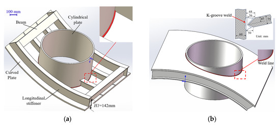
Figure 1.
Geometries of the investigated hybrid structure. (a) Assembly diagram of the hybrid structure; (b) main dimensions of the hybrid structure.
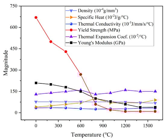
Figure 2.
Temperature-dependent material properties of DP980.
This study primarily examines the structural deformation induced by the complex spatial annular weld between the cylindrical shell and the curved panel. Such a weld type, commonly employed in shipbuilding and aircraft structures, presents significantly greater complexity than conventional linear weld. It poses substantial challenges in both practical welding operations and numerical simulations. From a computational perspective, the main difficulties lie in finite element modeling of the curved joint geometry and accurate heat source application along the three-dimensional weld path. The welds between the curved panel and stiffeners fall outside the present research scope, as this traditional joint configuration has been extensively investigated in the prior literature. To accommodate the thick-plate configuration, a K-groove joint design is employed which can ensure optimal weld quality and connection strength. The groove features 68 mm and 50 mm upper and lower openings, respectively; see Figure 1a. The multi-pass welding is completed using Shielded Metal Arc Welding (SMAW). Despite its higher cost, this approach is still the current solution for the welds of three-dimensional complex structures, since advanced robotic technology may not yet be well-suited for welding such intricate geometries.
3. Methodology
3.1. Integrated Welding Process Optimization Framework
Modern shipbuilding requires rigorous process planning before fabrication. An integrated design approach utilizing computational welding mechanics offers an effective methodology for manufacturing process optimization [22]. The method initiates with developing an initial plan that includes assembly sequences, welding sequences, and welding parameters, all determined according to structural configuration and material properties as well as other key parameters. Computational simulations then predict and analyze the welding-induced structural responses under this initial plan, generating quantitative data to guide design decisions. Through iterative optimization using simulation results, a final process plan meeting fabrication accuracy and quality specifications is obtained. Figure 3 illustrates the comprehensive workflow of this integrated design approach. The figure indicates that the validation of welding processes’ rationality requires quantitative comparison between predicted results (displacements, strains, and stresses) and designed threshold values.
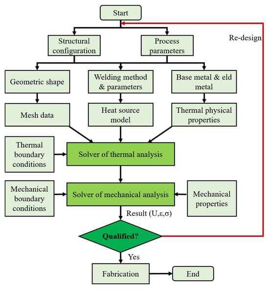
Figure 3.
Integrated method for welding process optimization based on computational welding mechanics.
3.2. Thermal-Elasto-Plastic Finite Element Method
This study implements a sequentially coupled thermo-elasto-plastic FEM to simulate the welding process of the hybrid structure, where the analysis is decoupled into sequential, thermal, and mechanical phases. The computational framework first solves the nonlinear transient heat transfer problem to determine the evolving temperature fields during welding, then maps these thermal results as thermal loads for the subsequent mechanical analysis that computes the structural responses, including deformations, stresses, and strain distributions. The adopted sequential coupling approach remains mechanically justified since the structural deformation exhibits negligible influence on thermal solutions during welding, while significantly improving computational efficiency compared to fully coupled schemes.
The thermal modeling incorporates a conventional nonlinear transient heat conduction formulation capable of capturing the following: (i) substantial temperature gradients, (ii) dynamic heat flux variations, (iii) evolving thermal boundaries, and (iv) internal energy transformations throughout the welding process. The governing energy balance equation takes the following form:
The parameters of the above equation are defined as follows: the instantaneous temperature field T represents the spatial and temporal thermal distribution, while K denotes the anisotropic thermal conductivity tensor that varies with temperature. The term Q accounts for the volumetric heat generation rate per unit volume, and ρ denotes the material mass density. The temperature-dependent specific heat capacity is designated as C, and t represents the temporal evolution of the heat transfer process. The complete solution of Equation (1) requires the simultaneous consideration of initial conditions defined in Equation (2), in which T0 specifies the initial thermal state of the system, together with the boundary conditions described in Equation (3).
where the boundary normal direction cosines (Nx, Ny, Nz) define surface orientation, while qs represents boundary heat flux. Heat transfer coefficients hc (convection) and hr (radiation) govern thermal losses, with Tr and T∞ denoting radiation and ambient temperatures, respectively. The radiation coefficient hr specifically characterizes weld zone radiative heat dissipation. In the present study, the convection and radiation conditions are reflected by the surface film condition defined in the ABAQUS software, namely hcr = 3.5 × 10⁻⁵ W/(mm2·°C).
In terms of the mechanical analysis, material yielding is evaluated using the von Mises yield criterion, with plastic region behavior governed by associated flow rules and isotropic hardening principles. The resultant strain field emerges from the superposition of three distinct components:
where the coefficient α characterizes the material’s thermal expansion behavior.
3.3. High-Efficiency Segmented Moving Heat Source Model
A conventional transient moving heat source has significant limitations in welding simulations of large complex structures, such as extremely long simulation time and high requirements in computer performance, especially for multi-pass welding. To efficiently compute the welding deformation in the hybrid structure, this study adopts a segmented moving heat source model in the simulation. Figure 4 shows a typical example of the schematic diagram of such a model widely adopted in engineering applications. The adopted heat source segment is slightly longer than that of the colored section shown in Figure 4. Deng et al. [23] have applied a simplified moving heat source to investigate the residual stress in a dissimilar metal girth welded pipe. Figure 5 shows the distribution of such a model, which is similar to that used in the current paper.
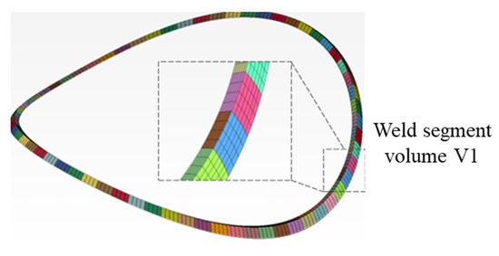
Figure 4.
Schematic diagram of segmented moving heat source.
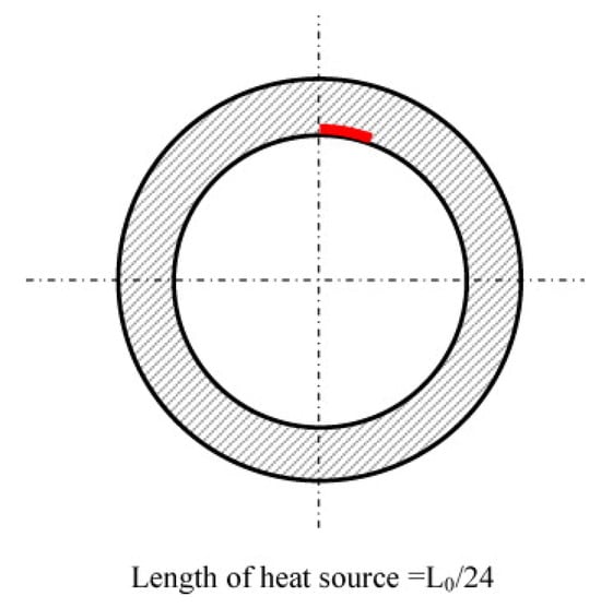
Figure 5.
Schematic diagram of a simplified moving heat source used to weld a thick-walled pipe provided by Deng et al. [23].
It can be observed from Figure 4 and Figure 5 that the idealized model simplifies the moving heat source into multiple band-shaped segments with uniform cross-sectional temperature distribution along the weld path. Within each discrete segment, a stationary heat source is simultaneously applied to all finite elements. These localized heat source applications are sequentially activated along the weld path direction, thereby effectively emulating macroscopic heat source propagation. Kiyoshima et al. [11] have proven that the segmented moving heat source can considerably reduce welding simulation time while maintaining the required computational accuracy. Furthermore, Deng et al. [23] also verified the feasibility of the simplified model based on the comparison between numerical and experimental results. This advantage makes it a practical tool for the analysis of large-scale engineering structures.
The volumetric heat flux qf of the segmented heat source is governed by the welding heat input, travel speed, and segment geometry, as mathematically defined in Equation (5). Additionally, the heating time t1 and cooling time t2 for each segment of the heat source are described by Equations (6) and (7), respectively. A specific code is designed for applying the segmented moving heat source in multi-pass welding simulation considering different welding sequences.
where η is the arc efficiency; VH is the volume of the segmented heat source; α is the adjusting coefficient; U and I are the arc voltage and current, respectively.
where r is the heat source radius; ν is for the welding speed; l is length of the segmented heat source.
4. Prediction of Welding Deformation
4.1. Preliminary Design of Welding Process
Before applying the segmented moving heat source, the curved panel and cylindrical shell are temporarily joined by tack welds to maintain dimensional stability during fabrication. A total of 74 weld seams are carefully designed for the K-groove joint. This joint can be regarded as a double-sided double-bevel groove. The welding sequence for all passes is presented in Figure 6a, which is denoted by the numerical order. As indicated in Figure 6a, the preliminary welding scheme employs a globally symmetric welding sequence with local asymmetric variations. The welds on both sides are divided into three major zones, where symmetry is maintained at the zonal level but not at individual layers. In the next section, the welding sequence will be further optimized at the individual layers. Prior to heating the subsequent weld bead, the current bead is cooled to a specified temperature through dedicated cooling analysis steps.
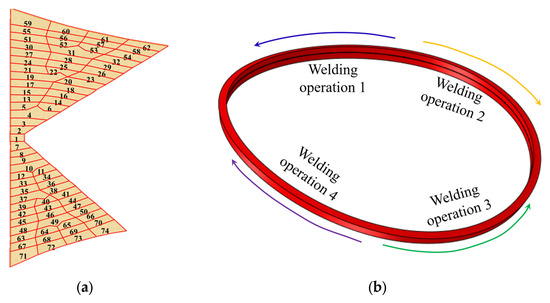
Figure 6.
Welding sequence and direction. (a) Preliminary arrangement of weld beads; (b) simultaneously symmetrical welding.
A coordinated four-operator simultaneous welding approach is employed, in which travel directions are systematically arranged according to symmetry principles, as illustrated in Figure 6b. It is well known that symmetric welding path planning also contributes to welding distortion mitigation for circular or cylindrical structures. Note that no external fixturing is applied during welding in terms of the preliminary procedure, and distortion control is achieved solely through the inherent stiffness determined by the pre-assembled structure. The welding procedure specifications, including essential parameters such as current, voltage, and travel speed, are documented in Table 1.

Table 1.
Welding process parameters for stiffened curved panel.
Summing the time of all analysis steps yields the total duration of the welding simulation in ABAQUS software, which is 64,542 s. In practice, a single load case requires more than one week of continuous computational runtime to complete the temperature and stress analyses. If a transient moving heat source is adopted, the simulation time will far exceed one week. It should be noted that the iterative cooling time of the structure after completion of all weld passes is 4000 s. For all heating steps, the time increment between adjacent substeps is automatically determined by the software, which is generally below 0.1 s.
4.2. Finite Element Model
The finite element model of the hybrid structure is accurately modeled in PATRAN 2019 software based on its geometric dimensions. This model is subsequently transferred to ABAQUS 2023 software for welding simulation. In this model, the curved panel, cylindrical shell, and weld seams are discretized using solid elements, while the transverse and longitudinal stiffeners are modeled employing shell elements. More specifically, DC3D8 and C3D8R are selected as the types of solid elements during thermal analysis and mechanical analysis, respectively. DS4 and S4R are selected as the types of shell elements in these two steps, respectively. It is crucial to emphasize that welding simulations necessitate refined mesh resolution in the weld region, irrespective of the overall structural dimensions, due to the presence of steep thermal gradients. To improve computational efficiency while maintaining simulation accuracy, the finite element model implements a non-uniform meshing strategy. This approach utilizes an element size of 3.0 mm × 3.0 mm × 3.0 mm in the weld zone to precisely resolve these gradients, while progressively coarsening element sizes in regions are farther from the heat-affected zone. The cross-section of each weld bead, measuring approximately 8.0 mm, is represented by 2–3 finite elements. Such a size is consistent with that of the heat source, which is roughly equal to 13% of the wall thickness. The final finite element model consists of 286,125 nodes and 372,487 elements. Figure 7 displays the complete mesh distribution of the finite element model.
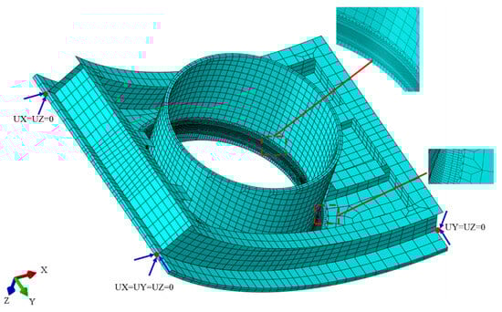
Figure 7.
FE model of the welded hybrid structure.
As mentioned previously, the stiffeners are modeled using shell elements. Because their locations experience minimal thermal effects during welding, it means that strain levels due to welding are insufficient to induce plastic deformation at these locations. The reinforcing components primarily function to enhance structural rigidity against welding-induced distortion. Another point is that the adoption of shell elements significantly reduces modeling complexity at the curved panel–stiffener interfaces. To achieve effective load transfer between these two structural components, a shell-to-solid coupling method provided by the ABAQUS software is implemented in the welding simulation.
In the preliminary welding procedure, the finite element model neglects artificial fixation constraints that could influence the deformation pattern. To ensure numerical convergence while maintaining the unconstrained nature of the physical setup, three-point constraints are implemented at three nodes of the model, as illustrated in Figure 7. In the figure, UX, UY and UZ respectively represent displacement constraints in the x-direction, y-direction and z-direction. The applied boundary conditions only enable eliminating rigid body motion degrees of freedom during computation.
Figure 8 shows the temperature variation at the weld zone during the welding process and the final temperature distribution of the hybrid structure after cooling. As can be seen, the peak temperature reaches approximately 2500 °C in the weld pool filling stage, while during the cover pass welding, the maximum temperature decreases to about 1500 °C. After complete cooling, the final temperature of the entire structure falls below 28 °C.
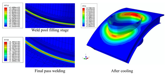
Figure 8.
Variation in the temperature field (unit: °C).
4.3. Welding Deformation Results
In this subsection, the structural deformation results based on spatial multi-pass welding simulation are considered, which correspond to the preliminary welding procedure. The results indicate that the dominant deformation modes of the hybrid structure are manifested as the out-of-plane deformation of the curved panel and cylindrical shell together with the radial deformation of the latter member. Characteristics of the two kinds of structural deformation are analyzed below.
- (a)
- Out-of-plane deformation
The out-of-plane deformation distribution of the stiffened curved panel is presented in Figure 9a. Herein, the welding deformation is defined as node dislocation. As shown, the long-edge regions exhibit significant positive z-direction deformation, while areas near the weld seams display prominent negative z-direction deformation, with a maximum relative deviation of 4.8 mm. The out-of-plane deformation of the stiffened curved panel likely originates from angular distortions at the welded joint, where successive weld passes induce significant through-thickness temperature gradients between the upper and lower surfaces. Notably, the deformation magnitude varies along the long free edge, being relatively smaller near the intersections of transverse and longitudinal stiffeners (points Pa, Pb, Pc, and Pd); see Figure 9b. This indicates that applying constraint supports along the free edge helps suppress the overall structural deformation.
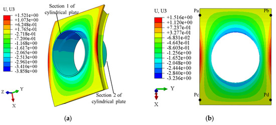
Figure 9.
Welding deformation of hybrid structure under the initial scheme (unit: mm). (a) Overall structural deformation; (b) out-of-plane distortion of curved panel.
In terms of the cylindrical shell, it deforms mainly in the negative z-direction, and the maximum displacement occurs near the negative x-axis. The cylindrical shell shows larger z-direction deformation than the stiffened curved panel. This difference likely stems from fewer supporting members. Nevertheless, the overall out-of-plane deformation of the integrated model remains relatively small (<5 mm), primarily due to the great thicknesses of both structural components, which provides enhanced structural stiffness.
- (b)
- Radial deformation
The two end sections of the cylindrical shell described in Figure 9a are selected to examine the radial deformation. Obviously, the cylindrical coordinate system is more suitable than the Cartesian coordinate system for describing the radial deformation. Accordingly, a local cylindrical coordinate system is defined at the center of the cylindrical shell, as shown in Figure 10. It should be noted that the symbols “T”, “R”, and “Z” denote the axial, radial, and circumferential directions of the cylindrical shell. Herein, the axial deformation is actually equivalent to the z-direction deformation which has been presented previously. It is known from the geometric features of circular structures that the circumferential deformation is closely related to the radial deformation. Therefore, the latter is discussed in detail as follows.
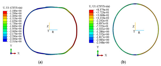
Figure 10.
Radial distortion of cylindrical shell (scale factor: 50, unit: mm). (a) Section 1 of cylindrical shell; (b) Section 2 of cylindrical shell.
Figure 10 illustrates the radial deformation distribution of the two sections after welding. Herein, the deformation is magnified by a factor of 50 to enhance visibility. It is apparent that the ends of the cylindrical shell deform into an elliptical geometry. The two end sections exhibit opposite-phase radial deformation patterns: Section 1 demonstrates outward expansion along the longitudinal direction, whereas Section 2 undergoes inward contraction. The relative magnitudes of the radial deformation are 3.7 mm for Section 1 and 3.1 mm for Section 2, respectively. Welding deformation is often accompanied by residual stress. Figure 11 shows the distribution of such imperfections around the weld seam after cooling. It can be observed that the maximum von Mises stress reaches 664 MPa appearing in the weld beads, while the stress amplitude is lower in areas farther away from these regions. In the subsequent analysis, constrained boundary conditions will be incorporated to mitigate the radial deformation.
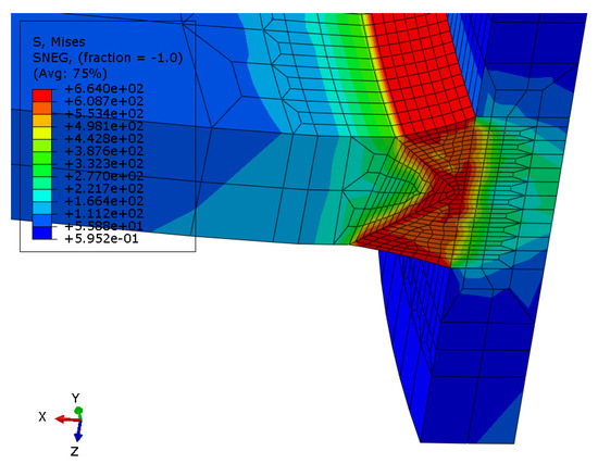
Figure 11.
Residual stress distribution around the weld seam (unit: MPa).
5. Welding Deformation Control
5.1. Optimization Scheme
Welding-induced deformations are intrinsically linked to the employed welding procedure. Suboptimal welding sequence or inadequate structural constraints may lead to significant distortion and consequently compromising construction accuracy. This section presents an optimized welding strategy building upon the preliminary scheme outlined earlier, incorporating both welding sequence refinement and mechanical constraint implementation. Such an optimization scheme may offer notable practical utility in engineering applications.
In contrast to the welding sequence illustrated in Figure 6, the optimized scheme considers a symmetrical, layer-by-layer sequence for bilateral weld passes of the K-groove, as shown in Figure 12a. All welding parameters, except for the interlayer sequencing, remain consistent with the initial scheme. Furthermore, given the significant impact of radial deformation on the assembly accuracy of the cylindrical shell, symmetrically radial support structures are arranged on the inner walls of the two end sections. These structures are angularly spaced at 60° intervals, as illustrated in Figure 12b. They play a critical role in mitigating the welding distortion and are subsequently removed upon completion of the cooling phase.
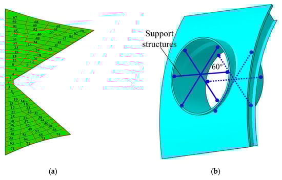
Figure 12.
Welding deformation control strategy for hybrid structure. (a) Optimized weld pass sequencing; (b) implementation of support structures.
5.2. Welding-Optimized Deformation Control
Similarly, taking the out-of-plane deformation of the hybrid structure and the radial deformation of the cylindrical shell as representative cases, the present subsection systematically analyzes how welding process optimization influences the structural distortion.
- (a)
- Out-of-plane deformation
As presented in Figure 13a, the peak out-of-plane deformation, localized in the weld-adjacent region, manifests as a −3.2 mm displacement along the z-direction. In contrast, the panel periphery demonstrates opposing deformation behavior, with positive z-direction displacements peaking at 1.03 mm. Figure 13b delineates the complete deformation profile of the stiffened curved panel, with an amplitude ranging from −2.7 mm to 1.0 mm. The maximum relative out-of-plane deformation is approximately 3.7 mm. Compared to the initial welding scheme, the deformation amplitude is reduced by approximately 22.9%. This fact confirms the effectiveness of the welding procedure optimization in minimizing the deformation. It can be understood that the implementation of a symmetrical layer-by-layer welding sequence can reduce the temperature gradient between bilateral weld seams. Consequently, both angular distortion and out-of-plane deformation of the panel are significantly reduced.
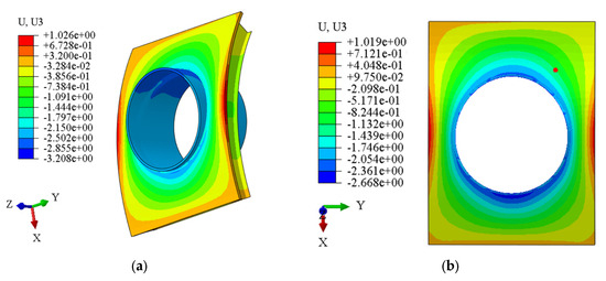
Figure 13.
Welding deformation of the hybrid structure under the optimized scheme (unit: mm). (a) Overall structural deformation; (b) out-of-plane distortion of curved panel.
- (b)
- Radial deformation
Figure 14 compares the radial displacements at the upper and lower end sections of the cylindrical shell between initial and optimized schemes. The results clearly show that at measurement locations Ta and Tb on Section 1, where the initial radial displacements were particularly large, the displacements have been successfully reduced by approximately 0.8 mm and 0.6 mm, respectively. In a similar pattern, at monitoring points Tc and Td on Section 2, where significant radial displacements were also observed, the results show reductions of approximately 0.7 mm and 1.1 mm, respectively. The maximum relative radial displacements at the upper and lower end sections are decreased by approximately 35.1% and 47.3%, respectively. This means that the mechanical constraints adopted in the optimized scheme can enhance the overall radial stiffness of the cylindrical shell, and therefore contribute to suppressing the radial distortion.
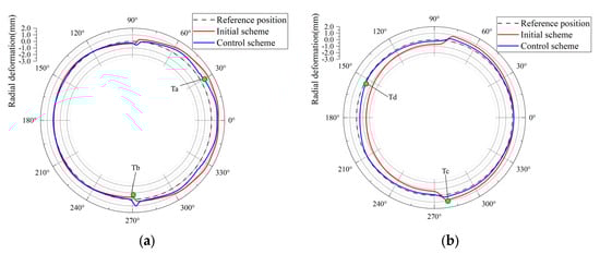
Figure 14.
Comparison of radial deformation of the cylindrical shell. (a) Section 1 (upper end); (b) Section 2 (lower end).
6. Conclusions
This study investigates welding deformation prediction and control for a stiffened curved panel–cylindrical shell hybrid structure. Through thermo-elasto-plastic finite element analysis, a simulation approach of the welding process is developed for the hybrid structure. The simulation characterizes the welding deformation patterns of the stiffened curved panel and cylindrical shell. Building on these insights, we propose an integrated process control scheme combining optimized welding sequences with mechanical constraints. The main conclusions are as follows:
- (1)
- The welding deformation of the hybrid structure is dominated by out-of-plane deformation of the stiffened curved panel together with radial deformation of the cylindrical shell. The maximum relative magnitudes of these two kinds of deformation under the initial welding scheme are 4.8 mm and 3.7 mm, respectively.
- (2)
- Welding sequence optimization can significantly reduce the out-of-plane deformation of the stiffened curved panel. Furthermore, rigid supports applied on the inner wall of the cylindrical shell’s ends are also able to considerably decrease its radial deformation. According to numerical simulation, the corresponding reduction rates reach 22.9% and 47.3% for these typical deformation modes.
- (3)
- The developed numerical simulation approach offers an effective computational tool for welding process optimization in integrated design frameworks. Future work should explore its extension to more complex steel structures and industrial-scale validation.
Author Contributions
Conceptualization, B.W. and C.W.; methodology, B.W. and X.L.; software, J.Y.; writing—original draft preparation, B.W.; writing—review and editing, Z.C. and A.W.; visualization, J.Y. All authors have read and agreed to the published version of the manuscript.
Funding
This research received no external funding.
Data Availability Statement
Data will be made available from the corresponding author by request.
Conflicts of Interest
The authors declare no conflicts of interest.
References
- Xia, J.; Jin, H. Numerical study of welding simulation and residual stress on butt welding of dissimilar thickness of austenitic stainless steel. Int. J. Adv. Manuf. Technol. 2017, 91, 227–235. [Google Scholar] [CrossRef]
- Yi, J.; Chen, Z.; Sun, C.; Li, J.; Li, D. Prediction of welding deformation in stiffened structures using a data-driven def-GAN model. J. Constr. Steel Res. 2024, 221, 108916. [Google Scholar] [CrossRef]
- Choobi, M.S.; Haghpanahi, M.; Sedighi, M. Prediction of welding-induced angular distortions in thin butt-welded plates using artificial neural networks. Comput. Mater. Sci. 2012, 62, 152–159. [Google Scholar] [CrossRef]
- Long, H.; Gery, D.; Carlier, A.; Maropoulos, P.G. Prediction of welding distortion in butt joint of thin plates. Mater. Des. 2009, 30, 4126–4135. [Google Scholar] [CrossRef]
- Maekawa, A.; Kawahara, A.; Serizawa, H.; Murakawa, H. Fast three-dimensional multipass welding simulation using an iterative substructure method. J. Mater. Process. Technol. 2015, 215, 30–41. [Google Scholar] [CrossRef]
- Nishikawa, H.; Serizawa, H.; Murakawa, H. Actual application of FEM to analysis of large scale mechanical problems in welding. Sci. Technol. Weld. Join. 2007, 12, 147–152. [Google Scholar] [CrossRef]
- Zhou, H.; Shen, C.; Wang, J. Computational analysis of welding radial deformation of typical pressure cylindrical shell with ring stiffener. Int. J. Nav. Archit. Ocean Eng. 2022, 14, 100460. [Google Scholar] [CrossRef]
- Chen, Z.; Chen, Z.; Shenoi, R.A. Influence of welding sequence on welding deformation and residual stress of a stiffened plate structure. Ocean Eng. 2015, 106, 271–280. [Google Scholar] [CrossRef]
- Perić, M.; Tonković, Z.; Rodić, A.; Surjak, M.; Garašić, I.; Boras, I.; Švaić, S. Numerical analysis and experimental investigation of welding residual stresses and distortions in a T-joint fillet weld. Mater. Des. 2014, 53, 1052–1063. [Google Scholar] [CrossRef]
- Zhou, H.; Yi, B.; Niu, Y.; Wei, B.; Du, S.; Zhao, H.; Liu, J.; Wang, J. Application of efficient TEP FE computation on accurate fabrication of cylindrical leg structure of jack-up rig. Ocean Eng. 2020, 196, 106812. [Google Scholar] [CrossRef]
- Kiyoshima, S.; Deng, D.; Ogawa, K.; Yanagida, N.; Saito, K. Influences of heat source model on welding residual stress and distortion in a multi-pass J-groove joint. Comput. Mater. Sci. 2009, 46, 987–995. [Google Scholar] [CrossRef]
- Fu, G.; Lourenco, M.I.; Duan, M.; Estefen, S.F. Effect of boundary conditions on residual stress and distortion in T-joint welds. J. Constr. Steel Res. 2014, 102, 121–135. [Google Scholar] [CrossRef]
- Desai, R.S.; Bag, S. Influence of displacement constraints in thermomechanical analysis of laser micro-spot welding process. J. Manuf. Process. 2014, 16, 264–275. [Google Scholar] [CrossRef]
- Wang, Y.; Feng, G.; Pu, X.; Deng, D. Influence of welding sequence on residual stress distribution and deformation in Q345 steel H-section butt-welded joint. J. Mater. Res. Technol. 2021, 13, 144–153. [Google Scholar] [CrossRef]
- Wang, J.; Zhao, H.; Zou, J.; Zhou, H.; Wu, Z.; Du, S. Welding distortion prediction with elastic FE analysis and mitigation practice in fabrication of cantilever beam component of jack-up drilling rig. Ocean Eng. 2017, 130, 25–39. [Google Scholar] [CrossRef]
- Zhang, C.; Li, S.; Sun, J.; Wang, Y.; Deng, D. Controlling angular distortion in high strength low alloy steel thick-plate T-joints. J. Mater. Process. Technol. 2019, 267, 257–267. [Google Scholar] [CrossRef]
- Yi, J.; Lin, J.; Chen, Z.; Chen, T. Prediction and controlling for welding deformation of propeller base structure. J. Ocean Eng. Sci. 2021, 6, 410–416. [Google Scholar] [CrossRef]
- Wu, H.; Dong, H.; Guo, Y.; Yuan, F.; Ke, Y. Reverse deformation design for bending control in welding of ring stiffeners. Int. J. Press. Vessel. Pip. 2025, 213, 105362. [Google Scholar] [CrossRef]
- Luo, Y.; Jiang, W.; Yang, Z.; Wang, C.; Jin, Q.; Gao, T.; Yan, G.; Tu, S.; He, Y. Using reinforce plate to control the residual stresses and deformation during local post-welding heat treatment for ultra-large pressure vessels. Int. J. Press. Vessel. Pip. 2021, 191, 104332. [Google Scholar] [CrossRef]
- Hu, X.; Sun, X.; Raghavan, K.; Comstock, R.J.; Ren, Y. Linking constituent phase properties to ductility and edge stretchability of two DP 980 steels. Mater. Sci. Eng. A 2020, 780, 139176. [Google Scholar] [CrossRef]
- Lee, E.H.; Yang, D.Y.; Yoon, J.W.; Yang, W.H. Numerical modeling and analysis for forming process of dual-phase 980 steel exposed to infrared local heating. Int. J. Solids Struct. 2015, 75, 211–224. [Google Scholar] [CrossRef]
- Azari-Dodaran, N.; Ahmadi, H. Static behavior of offshore two-planar tubular KT-joints under axial loading at fire-induced elevated temperatures. J. Ocean Eng. Sci. 2019, 4, 352–372. [Google Scholar] [CrossRef]
- Deng, D.; Kiyoshima, S.; Ogawa, K.; Yanagida, N.; Saito, K. Predicting welding residual stresses in a dissimilar metal girth welded pipe using 3D finite element model with a simplified heat source. Nucl. Eng. Des. 2011, 241, 46–54. [Google Scholar] [CrossRef]
Disclaimer/Publisher’s Note: The statements, opinions and data contained in all publications are solely those of the individual author(s) and contributor(s) and not of MDPI and/or the editor(s). MDPI and/or the editor(s) disclaim responsibility for any injury to people or property resulting from any ideas, methods, instructions or products referred to in the content. |
© 2025 by the authors. Licensee MDPI, Basel, Switzerland. This article is an open access article distributed under the terms and conditions of the Creative Commons Attribution (CC BY) license (https://creativecommons.org/licenses/by/4.0/).