Abstract
In this paper, a generic computational framework, based on the generalized-mode approach, is developed for the fully coupled time-domain aero-hydro-servo-elastic analysis of Hybrid Offshore Wind and Wave Energy Systems (HOWiWaESs), consisting of a Floating Offshore Wind Turbine (FOWT) and several wave energy converters (WECs) mechanically connected to it. The FOWT’s platform and the WECs of the HOWiWaES are modeled as a single floating body with conventional rigid-body modes, while the motions of the WECs relative to the FOWT are described as additional generalized modes of motion. A numerical tool is established by appropriately modifying/extending the OpenFAST source code. The frequency-dependent exciting forces and hydrodynamic coefficients, as well as hydrostatic stiffness terms, are obtained using the traditional boundary integral equation method, whilst the generalized-mode shapes are determined by developing appropriate 3D vector shape functions. The tool is applied for a 5 MW FOWT with a spar-type floating platform and a conic WEC buoy hinged on it via a mechanical arm, and results are compared with those of other investigators utilizing the multi-body approach. Two distinctive cases of a pitching and a heaving WEC are considered. A quite good agreement is established, indicating the potential of the developed tool to model floating HOWiWaESs efficiently.
1. Introduction
1.1. Motivation
Modern societies are in great need of clean and renewable energy supplies. Their efficient exploitation, directly related to the EU energy policies, can contribute to energy security enhancement, economic growth and reductions in greenhouse gas emissions. Offshore wind and wave energy comprise two of the most important renewable energy sources in the marine environment. Many large-scale commercial offshore wind farms have been installed and are operating in Europe. Still, the visual and spatial disturbances that such projects may cause near the shore, combined with the fact that 80% of total wind energy is found at water depths greater than 60 m [1], have led to the need to exploit offshore wind in deep waters. As for wave energy, its potential is estimated at 10 TW, which can cover from 15% to 66% of the global energy consumption, depending on relevant exploitability levels [2]. The above percentages are equivalent with the power supply from 800 nuclear plants [3].
In the case of offshore wind energy, the “going deeper” trend, where stronger and more consistent winds exist, has created new technological and financial challenges that should be adequately addressed in order to achieve the sustainable and cost-efficient realization of offshore wind energy projects [4]. At the same time, wave energy technology currently represents one of the most advanced and rapidly developed ocean energy technologies, which is anticipated to be commercially viable in the short–medium term [5]. Specifically, a variety of wave energy converters (WECs) with different working principles has been investigated, developed, and tested so far, aiming to overcome existing technological barriers and achieve competitiveness with other renewable energy sources. Therefore, cost reduction constitutes a challenge that both the offshore wind and wave energy sectors share. It may, thus, be beneficial to deploy floating Hybrid Offshore Wind and Wave Energy Systems (HOWiWaESs) that enable the simultaneous exploitation of the corresponding energy potential in deep waters by combining an Offshore Wind Turbine (OWT) and WECs in one structure. This synergy may offer multiple economic, technical and licensing benefits, such as cost reduction through shared grid infrastructure, operation and maintenance logistics, increased energy yield, smooth and highly available power output, common regulatory frameworks, etc. [6].
1.2. Literature Review
Up to now, different concepts of HOWiWaESs have been proposed by various researchers who investigated their performance (dynamic behavior and power production) either numerically or experimentally. Plenty of them have been summarized by [7], whilst [8] classified several of them based upon WECs’ working principles and simulation methods.
Most of the existing numerical investigations have been realized by developing integrated but concept-driven models in the time domain, while utilizing the multi-body approach. In this approach, the FOWT and the WECs are allowed to move freely and independently in their rigid-body Degrees Of Freedom (DOFs), while any physical connections (i.e., hinges, joints, etc.) are included in the equations of motion in the form of additional external forces representing the relevant motion constraints [9,10,11,12,13,14,15]. Within this framework, an integrated aero-hydro-servo-elastic analysis of a moored spar-type FOWT and a torus-like heaving WEC (Figure 1a) was conducted by [16,17]. The WEC was installed around the FOWT like a ring through appropriate connections, while power was absorbed through a linear Power Take-Off (PTO) mechanism, actuated from the WEC’s heave motion. The hydrodynamic coupling was considered in the time domain by including in the equation of motion non-zero off-diagonal hydrodynamic and hydrostatic stiffness terms. The concept was also physically tested and validated by [18,19].
Additionally to the above, Bachynski and Moan [20] modeled a Tension-Leg Platform (TLP) wind turbine with a point absorber on each one of its three pontoons (Figure 1b). Each WEC was attached to a guide beam connected with the TLP pontoons. Guide beams either directly connected or hinged to the TLP were examined, leading respectively to pure heaving or rotating devices. Luan et al. [21] introduced an HOWiWaES concept (Figure 1c) consisting of a 5 MW wind turbine on a catenary-moored semi-submersible platform and rotating flap-type, elliptical-shaped WECs hinged on each one of the platform’s pontoons. The same system was numerically investigated by [22,23,24], whilst experiments were conducted by [18,19,25] to validate the relevant numerical models. Another HOWiWaES (called “WindWEC”, Figure 1d) combining a moored spar-type 5MW FOWT with a conical WEC attached to it by means of a mechanical arm was suggested and examined in [26]. The arm was rigidly connected to the WEC and hinged on the FOWT’s spar, where a linear PTO mechanism was deployed to absorb power through the rotation of the arm relative to the spar. It is mentioned that in all the above numerical investigations the hydrodynamic coupling among the separate bodies was not taken into account. Still, for the latter HOWiWaES (i.e., the “WindWEC”) a coupled multi-body analysis was implemented in the frequency domain by [27,28].
Finally, a catenary-moored HOWiWaES was introduced and experimentally validated by [29] (Figure 1e). The middle column of the triangular platform supported a 5 MW wind turbine, while each one of the rest three columns contained a semi-annulus-shaped Oscillating Water Column (OWC). For analyzing this HOWiWaES, appropriate vibrational modes representing the OWCs’ free surface oscillations were deployed additionally to the platform’s rigid-body DOFs, based on the generalized-mode approach.

Figure 1.
Examples of HOWiWaESs: (a) Spar FOWT and heaving WEC (reproduced from [16], with permission from Elsevier, 2025); (b) TLP FOWT and heaving or rotating WECs (reproduced from [20], with permission from ASME, 2025); (c) semi-submersible FOWT and flap-type WECs (reproduced from [21], with permission from ASME, 2025); (d) spar FOWT and hinged WEC (reproduced from [28], with permission from ASME, 2025); (e) semi-submersible FOWT and OWCs (reproduced from [29], with permission from ASME, 2025).
The generalized-mode or mode superposition approach presents an alternative method to conduct time-domain analysis of HOWiWaESs. In this case, the FOWT platform and the WECs of the HOWiWaES are modeled as a single floating body (substructure) with the conventional six rigid-body DOFs, while the motions of the WECs relative to the FOWT are described by introducing additional suitable modes of vibration, the so-called “generalized modes” or “generalized DOFs” (e.g., [30]). It can be regarded as an extension of the relevant method developed for solving hydroelasticity problems, where the generalized-mode concept is utilized to account for the structural deformations of deformable bodies under the wave action [31,32,33,34]. It is noted that the generalized modes can be considered either as “wet” or “dry”, depending upon the inclusion or the exclusion, respectively, of the surrounding fluid in the calculation of the mode shapes [35,36]. Compared to the multi-body approach, the generalized-mode approach offers the advantage of significantly reducing the size of the problem to be solved, by exploiting possible planes of symmetry; thus, it is favored for systems with several constraints or multiple connected bodies. Accordingly, the generalized-mode approach has been deployed in the case of floating platforms hosting multiple WECs (e.g., [37,38]).
1.3. Research Gaps and Paper’s Objective
Considering all the existing research on the time-domain analysis of floating HOWiWaESs, it can be concluded that the relevant developed and applied numerical models are concept-driven and the majority of them utilize the multi-body approach to account for the co-existence of the FOWT and the WECs. Moreover, in many investigations the existing hydrodynamic coupling is not explicitly considered. On the other hand, the generalized-mode approach has been utilized so far in a limited number of studies, including (a) the time-domain analysis of only one HOWiWaES concept (i.e., FOWT with OWCs [29]) or (b) the assessment of multiple WECs connected to a platform in the frequency (e.g., [37]) and time domains (e.g., [38]) under pure hydrodynamic loading.
Motivated by this and aiming at filling the above existing research gaps, in the present paper we develop a generic computational framework, driven by the generalized-mode approach, for the time-domain analysis of a floating moored HOWiWaES, consisting of one FOWT and several WECs that absorb wave power through their oscillations at specific DOFs. The proposed computational framework embraces the (a) development of appropriate 3D vector shape functions of general use to represent the generalized DOFs of the floating substructure resulting from the WECs’ existence, (b) extension of the Cummins equation of motion [39] to account for the above DOFs and (c) inclusion of non-diagonal hydrodynamic (frequency-dependent) and hydrostatic terms in the equation of motion (i.e., explicit consideration of the hydrodynamic coupling among the rigid-body and the generalized DOFs of the floating substructure). Successively, the framework is numerically realized by appropriately modifying/extending the source code of OpenFAST [40]. The corresponding numerical tool is then applied for the “WindWEC” HOWiWaES concept (Figure 1d) and results are compared with those of [26,27,28] obtained from the application of the multi-body numerical modeling approach.
Compared to existing multi-body approaches, the present investigation contributes to and advances the numerical modeling of HOWiWaESs by (a) developing a generic, thoroughly formulated numerical framework for those systems, (b) capturing explicitly the hydrostatic/hydrodynamic coupling between the FOWT’s platform and the WECs, (c) avoiding the complexity of multi-body analysis with regard to appropriate restraint imposition and (d) offering the potential to reduce the computational time in the prerequisite frequency-domain analysis in cases of symmetrical layouts, since planes of symmetry can be efficiently utilized when describing the 3D vector shape functions. Additionally to the above, the present work is novel, since it comprises the first integrated extension of OpenFAST software, V2.3 (National Renewable Energy Laboratory NREL, Golden, Colorado, USA) regarding the generalized-mode approach,
The remainder of the paper is organized as follows: In Section 2 the main aspects of the computational framework developed in the present paper are described, while Section 3 includes the numerical formulation of the examined problem. In Section 4, the main characteristics and the numerical configuration of the examined HOWiWaES are described, with the relevant results being presented and discussed in detail in Section 5. Finally, in Section 6, the main conclusions of this study are cited along with suggestions for future research.
2. Computational Framework
The computational framework developed in the present paper is numerically realized by adequately modifying/extending the simulation capabilities of OpenFAST as shown in Figure 2. In this figure, the red dotted line includes (a) the main OpenFAST modules that have been appropriately modified so that an HOWiWaES can be modeled using the generalized-mode approach and (b) the required computational tools for the relevant frequency-domain analysis of the floating system.
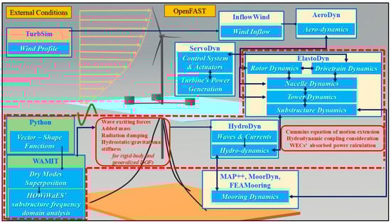
Figure 2.
Computational framework of the present investigation.
Starting with the latter analysis, the mode shapes of the generalized DOFs of the floating substructure (FOWT platform and WECs) representing the motion of each WEC relative to the FOWT platform are calculated through the establishment of appropriate 3D vector shape functions. The above calculation is implemented in vacuum (“dry” modes superposition approach). The mode shapes are successively used as input into a frequency-domain computational tool (e.g., WAMIT [41], Massachusetts Institute of Technology, Chestnut Hill, MA, USA) to obtain the frequency-dependent wave exciting forces and hydrodynamic coefficients (added mass and radiation damping), as well as the hydrostatic stiffness coefficients for both rigid-body and generalized DOFs. All the above quantities are then inserted into OpenFAST, where integrated time-domain analysis of the whole HOWiWaES under the combined wind and wave action is implemented. To achieve this, the HydroDyn and ElastoDyn modules of OpenFAST (Figure 2) have been appropriately modified so that (a) an extended equation of motion is formed and solved accounting for a floating substructure having both rigid-body and generalized DOFs, (b) the hydrodynamic coupling among the above DOFs is explicitly considered (inclusion of non-diagonal terms of the corresponding hydrodynamic and hydrostatic coefficients) and (c) the WEC’s power absorption ability is assessed.
The basic rationale adopted for modifying the above modules in OpenFAST is the increase in the number of DOFs in order to consider the generalized DOFs without altering though the mapping (notation and numbering) of the DOFs is already defined in the software. Accordingly, we increase the size of all vectors and matrices involved in the equation of motion and calculated within the HydroDyn and ElastoDyn modules, and the new elements are appropriately quantified or are set equal to zero for formulation purposes. For example, in the case of the HydroDyn module, which focuses on the quantification of loadings related to the floating substructure, the hydrodynamic/hydrostatic loading vector for its rigid-body DOFs is extended to include (a) zero elements for the DOFs of the HOWiWaES superstructure (i.e., the tower and the rotor-nacelle assembly) and, successively, (b) non-zero, appropriately quantified elements for the generalized DOFs of the floating substructure, which are being handled similarly to those of the rigid-body DOFs (e.g., error control interpolation is applied if needed). The opposite holds true for the ElastoDyn module, where the extended loading vectors obtain zero values for the elements related to the DOFs of the system’s substructure. An exception to the above are the inertia loads, since they do not contain any zero components, but they are modified inside ElastoDyn, so that the entire HOWiWaES is considered as one body with extra generalized DOFs. The extended equation of motion is solved in ElastoDyn, where, additionally, the loads of the mooring system (resulting from MAP++ or MoorDyn or FEAMooring modules) are taken into account along with the loads introduced from the PTO mechanisms of the WECs. Note that the Newton–Raphson iteration method is locally utilized inside the mooring system’s subroutines, without modifying the local mooring stiffness matrix, since only the FOWT’s platform is moored. More details about the relevant time-domain numerical formulation are provided in Section 3.
Finally, regarding input/output procedures, the input files of both HydroDyn and ElastoDyn retain, in general, their existing format; still, extra lines for specific input properties/options have been added (e.g., hydrodynamic/hydrostatic terms for the generalized DOFs, mass matrix terms of the HOWiWaES, initial simulation conditions, options of DOFs’ activation/deactivation, output selection options). The above are accompanied with user-friendly comments and explanations in the relevant input files. In an analogous manner, the existing format of the output files is kept, with the addition of extra columns for results related to the WECs (e.g., time series of the WECs’ displacement, velocity, acceleration and of the absorbed power). Subsequently to the above, all input–output subroutines of OpenFAST have been accordingly modified.
3. Numerical Formulation
We consider a moored HOWiWaES consisting of an FOWT and N WECs attached to the FOWT’s platform in any mechanically possible way. An indicative sketch of an HOWiWaES with a spar-type platform and N = 3 WECs is shown in Figure 3a. The following coordinate systems are introduced (Figure 3b): (a) the global XYZ coordinate system, with its origin placed on the Mean Water Level (MWL) at the FOWT’s platform’s center, (b) the platform’s local coordinate system XptfmYptfmZptfm, (c) the k-th, k = 1, …, N WEC’s local coordinate system XkYkZk, (d) the floating substructure’s local coordinate system Xsub,CMYsub,CMZsub,CM, located at the center of mass of the substructure’s submerged part, and (e) the tower’s local coordinate system XtYtZt with its origin at the tower base. It is noted that XptfmYptfmZptfm may coincide with XYZ; however, herein they are considered distinctive for generality purposes. For all coordinate systems, the x-axis (i.e., surge) points upwind and the y-axis (i.e., sway) is perpendicular to it, while the z-axis (i.e., heave) points vertically, opposite to the gravity field.
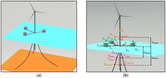
Figure 3.
(a) Indicative sketch of an HOWiWaES; (b) coordinate systems deployed for the time-domain analysis of an HOWiWaES.
3.1. Frequency-Domain Analysis and 3D Vector Shape Functions’ Calculation
The required frequency-domain hydrodynamic analysis of the HOWiWaES substructure (FOWT’s platform and the WECs) relies on the boundary integral equation method (BIEM), which is numerically realized using the WAMIT© software, V6.1/6.104S [41]. The analysis is based on a three-dimensional linear potential theory, where the whole multi-component floating substructure is considered as a single floating body that undergoes small-amplitude oscillations in the conventional six rigid-body DOFs (i.e., surge, sway, heave, roll, pitch and yaw; Figure 4a). Moreover, the motions of the WECs relative to the FOWT’s platform are taken into account through the inclusion of additional generalized DOFs. We assume that each WEC can translate and rotate along and around any axis relative to the platform. Accordingly, the k-th, k = 1, …, N WEC can have up to DOFs, k = 1, …, N, consisting of up to and translational and rotational, DOFs, respectively, which are defined similarly to the DOFs of a rigid body. Thus, the total number of generalized DOFs of the HOWiWaES substructure, Ngen, is given by the following equation:
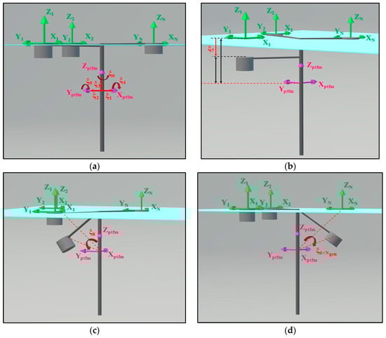
Figure 4.
HOWiWaES DOF illustrative example: (a) six rigid-body DOFs; (b) 7th “dry” generalized DOF (translational mode); (c) 8th “dry” generalized DOF (rotational mode); (d) ”dry” generalized DOF (rotational mode).
Assuming inviscid and incompressible fluid with irrotational flow, the velocity potential is introduced to describe the fluid motion. The diffracted and radiation potentials satisfy the Laplace equation everywhere in the fluid domain, while, additionally, they are subjected to the well-known linearized boundary conditions on the free surface, the sea bottom and the floating substructure [42] in order to form the 1st-order boundary value problem. The latter boundary conditions for a floating body with 6 rigid-body DOFs and Ngen generalized DOFs are formed as follows [33]:
where is the unit radiation potential of the j-th DOF of the floating substructure, n = (nx, ny, nz) is the unit normal vector and Uj, j = 7, …, 6 + Ngen is the 3D vector shape function of the j-th generalized mode, describing its “dry” mode shape.
The boundary integral equations for the unknown diffraction and radiation potentials on the body boundaries are formed using Green’s theorem, while the corresponding boundary value problem is, finally, solved based on a 3D low-order panel method.
In order to apply Equation (3), the 3D shape functions Uj, j = 7, …, 6 + Ngen have to be determined. In the present paper, those functions are calculated at the middle (centroid) of each panel of the floating substructure’s discretized wetted surface, by imposing an appropriate unit displacement (translation or rotation).
To further illustrate the above, Figure 4 shows an example of the generalized modes of an HOWiWaES floating substructure. For the sake of simplicity each WEC is assumed to have either a pure heaving motion (Figure 4b) or pure rotation (Figure 4c,d) relative to the FOWT’s platform (i.e., Nk = 1, k = 1, …, N and, hence, Ngen = N). Still, as already mentioned above, each WEC can be considered to move relative to the platform in more than one DOF.
Based on all the above, and assuming that the wetted surface of the floating substructure has been discretized using NP panels, a 3D vector shape function, Uj, for the j-th generalized DOF is formed as follows:
where uj (NP × 1), vj (NP × 1) and wj (NP × 1) are the component vectors of Uj along the Xptfm, Yptfm and Zptfm axes respectively.
Finally, the (6 + Ngen) × (6 + Ngen) frequency-dependent added mass (A) and radiation damping (B) matrices, the (6 + Ngen) × 1 frequency-dependent exciting force vector (F), and the (6 + Ngen) × (6 + Ngen) hydrostatic stiffness matrix (C) are obtained according to [33,43] with regard to the XptfmYptfmZptfm local coordinate system.
3.2. Time-Domain Numerical Formulation
In the time domain, the whole HOWiWaES, including the superstructure (i.e., tower and rotor-nacelle assembly (RNA)) is being modeled and analyzed by appropriately extending the numerical formulations of the corresponding modules in OpenFAST (Figure 2). The main modifications can be summarized as follows: (a) increase in the DOF number to account for the generalized DOFs of the floating substructure (Equation (5)), (b) relevant extension (size increase) of all matrices/vectors deployed in the equation of motion (Equations (6)–(8), (13) and (21)), (c) quantification of all matrices/vectors’ new terms related to the generalized DOFs (Equations (9)–(12), (14), (15), (17), (21) and (22)) and the PTO mechanisms (Equation (16)), and (d) extension and solution of the equation of motion including the generalized DOFs (Equations (6) and (7)). In the following paragraphs, all the above items are highlighted in detail.
We denote NO as the number of DOFs already considered in OpenFAST, where the first 6 correspond to the FOWT’s platform’s rigid-body modes and the rest (NO − 6) to the superstructure’s DOFs. In order to account for the Ngen generalized DOFs of the floating substructure, the total number of DOFs, M, for the whole HOWiWaES is increased up to
with indices in the range of NO + 1 up to M indicating the generalized DOFs.
The equation of motion of an HOWiWaES with M DOFs is formed as follows based on Newton’s second law:
where t is time; , and are, respectively, the (M × 1) vectors of the total loads acting on the HOWiWaES, of the inertial loads and of the induced accelerations, while m is the (M × M) mass matrix.
The total loading vector, , is then decomposed into the following components:
where and are the time-dependent (M × 1) loading vectors due to aerodynamics, turbine controller, hydrodynamics/hydrostatics (including loads originating from the mooring system and the PTO), any other source (e.g., viscous loads) and gravity, respectively. Contrary to and matrices, the terms of , and corresponding to the Ngen generalized DOFs are set equal to zero. The other terms are quantified according to the relevant existing formulations initially defined in [44].
The hydrodynamic/hydrostatic loading vector, , is successively decomposed as follows:
where , and are the (M × 1) vectors of the wave exciting, radiation and hydrostatic restoring loads, respectively, while and correspond to (M × 1) loading vectors resulting from the mooring system and the PTO mechanisms of the WECs.
Focusing on the wave exciting and radiation loading vectors, and I = 1, …, M terms are calculated according to [45] after applying appropriate modifications. More specifically, in the case of regular incident waves with circular frequency ω and amplitude A, Equations (9) and (10) are deployed, while for irregular incident waves described by a spectrum of spectral density S(ω) [46], Equations (11) and (12) are applied, by utilizing the well-known Cummins time-domain formulation [39].
In all the above equations, are the displacements, velocities and accelerations of the j-th DOF, j = 1, …, M of the HOWiWaES with regard to the XYZ coordinate system, while ε (Equation (11)) corresponds to the initial phase of each wave component following the normal Gauss distribution. Moreover, in Equation (12), is the (6 + Ngen) × (6 + Ngen) added mass matrix for infinite wave frequency, is the (6 + Ngen) × (6 + Ngen) retardation functions’ matrix and τ is an auxiliary dummy time variable. is calculated using the convolution integrals of Equation (13) [47], which captures the fluid memory effects [39,48].
The elements of the hydrostatic restoring and mooring system loading vectors (Equations (14) and (15) respectively) are calculated according to [49], after applying appropriate modifications to account for the floating substructure’s generalized DOFs. In Equation (15), and I, j = 1, …, M are the mooring system’s stiffness and damping terms.
Finally, the terms of the loading vector originating from the PTO mechanism of the WECs is obtained from Equation (16), assuming a linear damping system, actuated from the respective operational mode of each device. In this equation, , I, j = NO + 1, …, M are the PTO damping coefficients.
Coming back to Equation (6), we focus on the terms of the inertia loads’ vector related to the floating substructure. Accordingly, , I = 1, …, 6 and I = NO + 1, …, M are defined as follows:
In Equation (17), is the mass of the FOWT’s floating platform, , r = 1, …, N is the mass of the r-th WEC with the corresponding i-th, I = NO + 1, …, M generalized DOFs, and and denote, respectively, the index number of the first and the last rotative DOF of the r-th WEC. Furthermore, is the HOWiWaES submerged part’s position vector between the XptfmYptfmZptfm and Xsub,CMYsub,CMZsub,CM coordinate systems with respect to XtYtZt (Figure 3b). This (3 × 1) vector can be calculated as follows:
where are the coordinates of the Xsub,CMYsub,CMZsub,CM origin in the XYZ global coordinate system, whilst Xt, Yt, Zt are the (3 × 1) vectors indicating the relevant axes of the XtYtZt coordinate system [50].
As for and in Equation (17), those coefficients are used to indicate the nature of each generalized DOF. Accordingly, and of the i-th generalized DOF correspond to a translation of the WEC relative to the FOWT’s platform, while the opposite holds true for generalized DOFs that describe the WEC’s relative rotations. Moreover, and , i = 1, …, 6 and i = NO + 1, …, M are the (3 × 1) vectors of the partial linear and partial angular velocity, respectively, of the HOWiWaES XptfmYptfmZptfm and XtYtZt coordinate systems in the global coordinate system XYZ. In a similar manner, and are the (3 × 1) vectors of the partial linear velocity and its time derivative (i.e., liner acceleration), respectively, of the HOWiWaES substructure’s center of mass for the i-th DOF, i = 1, …, 6, and i = NO + 1, …, M, in the XYZ global coordinate system. Finally, and stand for the total HOWiWaES substructure and each WEC’s inertia dyadic, respectively, relatively to the XtYtZt coordinate system and they are calculated as follows:
where are the moments of inertia of the total HOWiWaES substructure and are the above quantities for each r-th WEC, along the X, Y and Z directions of the Xsub,CMYsub,CMZsub,CM coordinate system.
Focusing more on Equation (17), this equation quantifies the inertia loads at each DOF of the floating substructure in the global coordinate system. We recall that different coordinate systems are deployed within OpenFAST to describe the motions of an HOWiWaES. In order to transfer the corresponding inertia load to the global coordinate system (Figure 3a), appropriate coordinate transformation is required. The latter transformation is mathematically described by the right-hand side of Equation (17), where for each DOF the inertia load is expressed as the summation of two distinctive terms (one translational and one rotational). This in turn implies that the rotation of the system at a specific DOF also induces a portion of translational acceleration at the other DOFs and vice versa, as exists in the real physical problem.
As a final point, the gravitational loads (last component in Equation (7)) are obtained as follows:
where g is the acceleration of gravity, Z is the (3 × 1) unit vector of the Z global axis, and , , and are the (3 × 1), (3 × 1), (NO − 6) × 1 and (Ngen × 1) gravitational sub-vectors corresponding, respectively, to the i-th, i = 1, 2, 3, i = 4, 5, 6, i = 7, …, NO and i = NO + 1, …, M DOF of the HOWiWaES. The terms are calculated using Equation (22) below:
By replacing all matrices in the equation of motion (Equation (6)), a linear algebraic system is obtained, which can be solved by utilizing various numerical methods, such as the Gauss–Jordan elimination one.
It is, finally, noted that the power absorbed by each r-th WEC, r = 1, …, N at each time step t is calculated as follows [51]:
where is this WEC’s damping value and is the relative velocity between the WEC and the HOWiWaES platform.
4. Numerical Configuration of the Examined HOWiWaES
The numerical tool developed in the present investigation is applied for the WindWEC concept [26,27,28] (Figure 1d). This HOWiWaES consists of a three-bladed spar-type 5 MW FOWT inspired by the Hywind [52] concept and a conical WEC buoy inspired by the Wavestar [53] device. The buoy is attached to the FOWT via a mechanical arm, at a center-to-center distance equal to 20 m. The arm is a frame structure capable of handling all the mechanical/structural loads and transferring the bending moments and shear forces to the spar platform. At the joint where the arm is hinged on the FOWT’s platform, a linear PTO mechanism is placed, pumping oil as a result of the relative movement of the two parts (arm and spar). This oil flows in a cylinder-piston mechanism with rotating hydraulic motors; hence, electrical power is produced.
The structural properties of WindWEC are shown in Table 1. The moments of inertia of the WindWEC’s floating substructure (FOWT’s platform and WEC) have been calculated in the Xsub,CMYsub,CMZsub,CM coordinate system, by utilizing the Steiner theorem. It is also noted that contrary to [26,27,28], external damping and stiffness (apart from the mooring lines) terms have been considered for the FOWT’s platform, according to the relevant recommendations of [54]. Furthermore, the masses of both the FOWT platform and the mooring lines were slightly reduced based on the relevant heave free decay calibration tests (Figure 7b), whilst no clump weights were attached on the mooring lines. Finally, the ability of the WEC to turn against the wavefront (“weather vanning” configuration used as a passive method of adjustment) [26,27,28] is not considered in the present investigation. The HOWiWaES is placed in an area of 320 water depth, while the water density is taken equal to 1025 kg/m3.

Table 1.
Properties of the WindWEC’s floating substructure (FOWT’s platform together with the WEC) and its relevant components.
As for the WEC’s operation, two different operational cases are examined: (a) a pitching device (similarly to [26,27,28]), rotating around the arm’s joint, and (b) a pure heaving device. Accordingly, for each case one generalized DOF is taken into account corresponding, respectively, to a rotation (Figure 5b) and a vertical translation (Figure 5c) of the WEC relative to the FOWT. For both cases, five different PTO damping values are investigated, named as PTO 1, 2, 3, 4 and 5 (Table 2). For the pitching WEC, those values were obtained directly from [26], while for the heaving device they were calculated accordingly, using the PTO damping coefficients of the former WEC as a basis. It is also noted that, for comparison reasons, results related to the generalized DOF are presented in terms of the WEC’s vertical displacement relative to the MWL irrespective of the device operational mode.
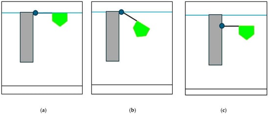
Figure 5.
WindWEC’s substructure’s: (a) undeformed position; (b) pitching WEC mode shape; (c) heaving WEC mode shape.
Table 2.
PTO damping values of WindWEC’s WEC.
5. Results and Discussion
5.1. Static Equilibrium
Aiming at assessing the stability of the WindWEC system, an initial simulation is performed, where the whole WindWEC system is left free to oscillate in the absence of any environmental load. The corresponding static offsets of the WindWEC’s floating substructure for both pitching and heaving devices and for all examined PTO values are shown in Figure 6. For all cases, the static offset for surge, sway, roll, pitch and yaw have values close to zero, indicating that for those DOFs the floating substructure returns to its initial position at the MWL. A small static offset below the MWL is observed in the case of heave (Figure 6c), ranging from 0.18 m for the pitching WEC to 0.38 m for the heaving one. Similarly, the heaving WEC illustrates a static vertical offset with a mean value of 0.04 m, while the relevant offset for the pitching device becomes a bit larger (mean value of 0.36 m). The above are mainly related to the strong hydrostatic coupling between the floating substructure’s heave mode with its generalized DOF, representing the motion of the WEC relative to the FOWT’s platform, as well as to the non-orthogonality of the imposed generalized mode. It is noted that the PTO value does not affect the static equilibrium position in any DOF.
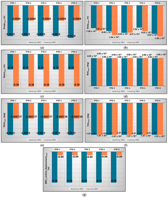
Figure 6.
Static offsets of the WindWEC in (a) surge; (b) sway; (c) heave; (d) roll; (e) pitch; (f) yaw; (g) WEC’s vertical displacement for both pitching and heaving devices and for all PTO values examined.
5.2. Free Decay Tests and Natural Periods
Free decay simulations have been conducted for the moored HOWiWaES by imposing a prescribed initial offset to the corresponding rigid-body and generalized DOF of the floating substructure and letting the system decay to its equilibrium position. The decay histories of the floating substructure’s six-rigid-body-mode displacement and the WEC’s vertical displacement are shown in Figure 7. As expected, due to the symmetry of the floating substructure and the mooring lines’ arrangement, the surge and sway responses (Figure 7a) coincide, while roll and pitch (Figure 7c) show insignificant differences. As for the WEC, its vertical displacement in the case of the pitching device (Figure 7e) is stabilized slightly below the MWL. This small deviation may be attributed to the formation of an asymmetric generalized hydrostatic stiffness matrix, resulting from its formulation. Furthermore, for both examined WEC operational modes (Figure 7e,f), the increase in the PTO damping leads, as expected, to a more rapid suspension of the WEC’s vertical displacement. This is more pronounced in the case of the pitching WEC (Figure 7e), where aperiodic oscillations are observed for PTOs 4 and 5, having the largest damping values.
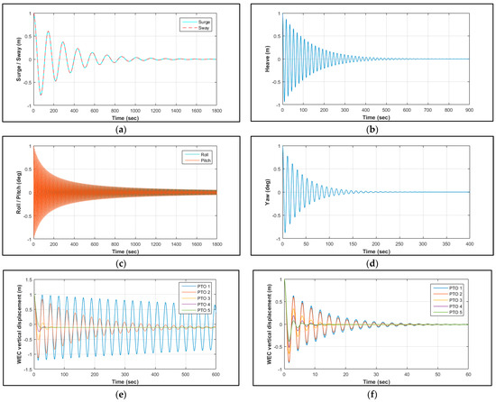
Figure 7.
WindWEC free decay histories of (a) surge and sway; (b) heave; (c) roll and pitch; (d) yaw; (e) pitching WEC’s vertical displacement; (f) heaving WEC’s vertical displacement.
By applying a Fourier analysis on the results of Figure 7, the natural periods of the WindWEC’s floating substructure are obtained and cited in Table 3. In this table, the natural periods of the FOWT’s platform (without the WEC) according to [26] and of the WindWEC concept as obtained from [28] according to the relevant numerical modeling are cited for comparison purposes. In the case of surge, sway and yaw DOFs, the natural periods of the present computational approach have higher values compared to [28], which is attributed to the consideration of a lighter mooring system in the current simulations for the reasons explained in Section 4 above. On the other hand, the fact that the floating substructure of WindWEC is modeled in the present investigation as one floating body leads to a stiffer structure in terms of inertia in heave, roll and pitch; hence, the corresponding natural periods are smaller when compared to [28].
Table 3.
Natural periods (sec) of WindWEC’s floating substructure.
As for the WEC’s natural period, it is significantly higher in the case of the pitching device. This is rational, since pitching and heaving WECs comprise two totally different devices in terms of functionality, making the pitching device stiffer due to its motion’s nature.
Focusing on the examined system’s dynamics, all the above differences observed between the present numerical tool and [28] can be analyzed from various relevant perspectives. In terms of resonance, the existence of a stiffer structure in heave and, especially, in roll and pitch compared to [28] implies that relevant resonance phenomena may become important for smaller-period (e.g., wind-driven) sea states. Still, the natural frequencies of all DOFs of the WindWEC’s floating substructure as obtained from the present numerical tool do not fall close to the characteristic 1P and 3P rotor frequencies. Considering power absorption, the FOWT’s power ability is not anticipated to be affected by the natural periods of the substructure, while the WEC’s natural periods suggest that the pitching device may be more efficient for sea states with larger peak periods. Overall, compared to the multi-body approach, the application of the generalized-mode approach may introduce differences or additional insights in the intrinsic dynamic features of an HOWiWaES, as in the case of the WindWEC. Understanding the modeling pillars of each approach is a key to acknowledge and assess potential implications that are introduced in the dynamics of the examined system.
5.3. Fully Coupled Dynamic Simulations
Having identified the main static and intrinsic dynamic characteristics of the examined HOWiWaES, a fully coupled aero-hydro-servo-elastic analysis is conducted under realistic wind and wave loads and results are compared with those of [28]. Specifically, the turbine class is considered as B, undergoing a Kaimal wind spectrum of 11 m/s average speed at the hub height (i.e., 90 m above MWL), while a sea state described by a Jonswap spectrum is taken into account with significant wave height Hs and peak period Tp, equal to 3.6 m and 10.2 s respectively. Four different Load Cases (LCs) are being examined, named LC 1, 2, 3 and 4, corresponding to wind and wave heading angles of 0 and 0, 0 and 30, 30 and 0, and 30 and 30 degrees, respectively, with 0 degrees indicating downwind direction (Figure 1d). In all LCs, the PTO value of the WEC is set equal to PTO 5, as [28] suggested (Table 2). In the latter study, it is not clarified whether the specific PTO value was selected based on a sensitivity or optimization analysis. The duration of the simulations is set to 4100 s, discarding the first 500 s due to transient effects.
Figure 8 and Figure 9 include some indicative time histories of the WindWEC’s responses, the windward mooring line’s (Line 1 in Figure 1d) fairlead tension and the produced power, aiming at illustrating the effect of the differently operating WECs and of the LCs on the above quantities. In the case of surge (Figure 8a), the consideration of a pitching or heaving device does not affect this response. This is not observed for heave (Figure 8c) and the WEC’s vertical displacement (Figure 9a), since the hydrodynamic coupling between the above rigid-body motion and the floating substructure’s generalized DOF is significantly high. Accordingly, the pitching device leads to larger (in absolute) values of the above responses under the respective LCs. Similarly to surge, the WEC’s operational mode does not have an impact on the power produced by the wind turbine for LC 3 (Figure 9c), while the power absorbed by the pitching device for LC 1 obtains larger values and depicts larger fluctuations when compared to the heaving WEC (Figure 9d). Finally, the effect of the different LCs—and especially of the wind heading angle—on the system’s response (Figure 8b) and on the fairlead tension of the windward mooring line (Line 1 in Figure 1d) is clearly illustrated (Figure 8d).
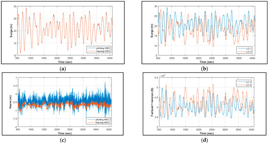
Figure 8.
Time series of WindWEC’s (a) surge response with heaving and pitching WEC (LC 1); (b) surge response with pitching WEC (for LCs 1 and 3); (c) heave response with heaving and pitching WEC (LC 4); (d) windward (Line 1) fairlead tension with heaving WEC (LCs 2 and 4).
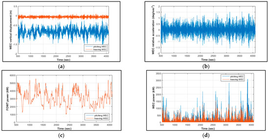
Figure 9.
Time series of WindWEC’s (a) pitching and heaving WEC’s vertical displacement with regard to MWL (LC 2); (b) pitching WEC’s relative acceleration with regard to FOWT’ platform (LC 4); (c) FOWT’s produced power with pitching and heaving WEC (LC 3); (d) pitching and heaving WEC’s absorbed power (LC 1).
All the above conclusions regarding the power produced by the FOWT (PFOWT) and the WEC (PWEC) of the examined HOWiWaES are further demonstrated in Figure 10, which includes the mean (PFOWTmean, PWECmean) and the standard deviation (PFOWTstd, PWECstd) of the time series of the above quantities for all LCs examined and for both pitching and heaving WECs. In this figure, results are also compared with those of [28], while PFOWTmean and PFOWTstd are additionally compared with the case of the isolated FOWT (without the WEC), which has been modeled using the traditional OpenFAST version [40].
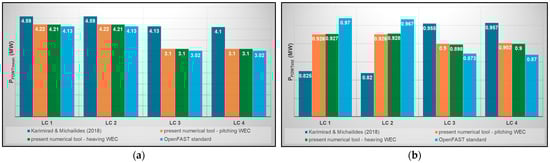
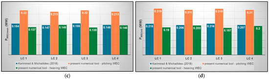
Figure 10.
Comparison of (a) PFOWTmean; (b) PFOWTstd; (c) PWECmean; (d) PWECstd with the results of [28] and with those of an isolated FOWT (without the WEC).
Focusing on the power produced by the FOWT (Figure 10a,b), the existence of insignificant differences in PFOWTmean and PFOWTstd for all LCs between the pitching and the heaving device in the case of the present tool’s application advocates the independence of the FOWT’s power produced by the WEC’s operational mode. When compared to [28], differences are observed in both PFOWTmean and PFOWTstd, with PFOWTmean values of the present numerical tool being ~25% lower for LCs 3 and 4. Still, the results of the present investigation are very close to those of the isolated FOWT. Accordingly, the former mentioned differences could be related to potential different modeling features/assumptions of [28] in the case of 30-degree wind heading.
As for the WEC’s mean absorbed power (Figure 10c), the PWECmean values obtained by [28] for all examined LCs are closer to those of the present numerical model in the case of the heaving WEC, whilst the pitching WEC seems to absorb around 50% larger amounts of energy compared to [28]. Since in [28] a pitching WEC was also considered, the latter difference is related to the inclusion of coupling via non-zero off-diagonal hydrodynamic/hydrostatic terms, which seems to lead to a noticeable enhancement of the WEC’s absorbed power in terms of mean values (see also Figure 11, where in the case of coupling neglection, the obtained results by the present numerical tool are very close to those of [28] and even a bit smaller). At the same time, however, larger PWECstd values are observed when compared to [28] (Figure 10d), advocating more intense power fluctuations. As for the heaving WEC, the existence of smaller vertical displacements relative to the FOWT’s platform (see for example Figure 9a for LC 2) leads to smaller PWECmean and PWECstd values, which are closer to the results of [28].
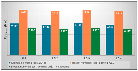
Figure 11.
Effect of hydrostatic/hydrodynamic coupling neglection on PWECmean [28].
Finally, the results of Figure 10 demonstrate clearly that the consideration of different wind and wave headings among the various LCs results in different mean and std values of both the FOWT’s and WEC’s power.
6. Conclusions
In the present investigation, we introduce a computational framework for the fully coupled aero-hydro-servo-elastic analysis of an HOWiWaESs in the time domain, utilizing the generalized-mode approach. As a basis of the present approach, we consider the FOWT’s platform and the WECs of the HOWiWaES as a single floating body with conventional rigid-body modes, while the motions of the WECs relative to the FOWT are described as additional generalized modes of motion. To achieve the above, appropriate 3D vector shape functions describing the “dry” mode shapes of the floating substructure are established and a numerical tool is developed by adequately modifying/extending the simulation capabilities of OpenFAST.
The novelty of the present research lies in (a) the development of a generic, thoroughly formulated numerical framework for HOWiWaESs driven by the generalized-mode approach, (b) the first extension of OpenFAST V2.3 software regarding the generalized-mode approach, (c) the hydrostatic/hydrodynamic coupling consideration, contrary to previous relevant studies, (d) the avoidance of complex restraint imposition that multi-body analysis demands and (e) the reduction in the computational burden of frequency-domain analysis (where hydrostatic/hydrodynamic coefficients are obtained) in cases of symmetrical layouts.
The developed numerical tool is applied for the WindWEC concept (catenary moored spar-type FOWT with a pitching conical WEC), initially introduced by [26], and the results are compared to those of [28], who utilized the multi-body numerical approach. Compared to the aforementioned previous studies, the present investigation (a) includes the hydrodynamic/hydrostatic coupling of the rigid-body and generalized DOFs of the floating substructure in both the frequency and time domains via non-zero off-diagonal terms in the hydrodynamic/hydrostatic matrices, (b) considers the FOWT platform and the mooring lines with slightly reduced masses (based on the relevant heave free decay calibration tests), (c) includes external damping and stiffness (apart from the mooring lines) for the FOWT’s platform, according to the relevant recommendations of [54], (d) discards the WEC’s ability to turn against the wavefront and (e) investigates WECs of two different operational modes (i.e., a pitching and a heaving device).
The static-equilibrium results have demonstrated a plausible behavior of the floating substructure (FOWT’s platform and WEC), with almost zero static offsets of the rotational and the translational (in the horizontal plane) rigid-body DOFs. Small static offsets below the MWL were observed for the heave and the generalized modes, due to the strong coupling between those two DOFs. As for the calculated natural periods of the WindWEC’s floating substructure, differences have been observed when compared to [26,28]. This is rational, since [26] considered the FOWT alone, while [28] modeled the substructure as two different bodies and calculated the natural periods of the FOWT’s platform separately, whilst in the present work the two bodies were assumed as one. Accordingly, the present WindWEC modeling led to (a) a more flexible substructure in surge, sway and yaw, mainly due to the consideration of a lighter mooring system, and (b) smaller natural periods in heave, roll and pitch, due to a stiffer structure in terms of inertia. Moreover, the different operational modes of the two examined WECs resulted in different intrinsic dynamic features among the pitching and the heaving device, with the latter one having a much lower natural period.
As for the fully coupled simulations under four different LCs of stochastic, aligned and misaligned wind and wave conditions, the corresponding results illustrated the direct effect of the differently operating WECs on heave, as well as on the WEC’s vertical displacement and power absorption ability. Regarding the FOWT’s power, its mean values resulting from the present numerical model were close to those of [28] when the wind heading angle was set to 0 degrees, while for 30 degrees the obtained results were around 25% smaller. Still, the results of the present investigation were very close to those of the isolated FOWT. Accordingly, the aforementioned observed differences could be related to the adoption of additional modeling features in [28] in the case of a 30-degree wind heading angle. As for the WEC, its mean absorbed power was almost 50% larger compared to [28] in the case of the pitching device, resulting mainly from the hydrodynamic/hydrostatic coupling inclusion, as also indicated by the relevant sensitivity analysis results. On the other hand, the mean power absorbed by the heaving WEC is smaller, with values almost equal to those of [28].
In general, the computational framework developed and presented in this investigation seems to constitute a robust and very promising way of assessing the performance of an HOWiWaES, offering the advantage of reducing significantly the size of the problem to be solved, by exploiting possible planes of symmetry. The present developed tool can be further applied for HOWiWaESs with more than one WECs and/or WECs with other modes of operation (e.g., flap-type WECs). Relevant challenges in this case could be the formation of appropriate 3D vector shape functions, as well as possible need for further extension of OpenFAST’s source code regarding specific motion principles of the operating devices. Moreover, non-linear PTO damping could be considered, as well as relevant non-diagonal damping terms. Finally, comparison with relevant experimental results (e.g., [18,19,25]) to experimentally validate and further establish the generality of the present numerical model also presents a future research item.
Author Contributions
Conceptualization, N.M., E.L. and P.T.; methodology, N.M. and E.L.; software, N.M.; validation, N.M.; formal analysis, N.M.; investigation, N.M.; data curation, N.M.; writing—original draft preparation, N.M.; writing—review and editing, E.L. and P.T.; visualization, N.M.; supervision, E.L. All authors have read and agreed to the published version of the manuscript.
Funding
This research received no external funding.
Data Availability Statement
The raw data supporting the conclusions of this article will be made available by the authors on request.
Acknowledgments
The authors would like to thank Constantine Michailides, Associate Professor at the International Hellenic University, and Madjid Karimirad, Associate Professor at Queen’s University Belfast, for providing data related to the WindWEC concept and for relevant discussions. The first author would also like to thank Jason Jonkam, principal engineer at NREL, for his constructive comments on the OpenFAST source code.
Conflicts of Interest
The authors declare no conflicts of interest.
References
- Cleantechnica. Available online: https://cleantechnica.com/2018/02/16/hywind-scotland-worlds-first-floating-wind-farm-performing-better-expected/ (accessed on 28 April 2025).
- Astariz, S.; Perez-Collazo, C.; Abanades, J.; Iglesias, G. Co-located wind-wave farm synergies (Operation & Maintenance): A case study. Energy Convers. Manag. 2015, 91, 63–75. [Google Scholar] [CrossRef]
- Slidesshare. Available online: https://www.slideshare.net/slideshow/wave-po-wer/32970038#1 (accessed on 28 April 2025).
- Vasileiou, M.; Loukogeorgaki, E.; Vagiona, D.G. GIS-based multi-criteria analysis for site selection of hybrid offshore wind and wave energy systems in Greece. Renew. Sustain. Energy Rev. 2017, 73, 745–757. [Google Scholar] [CrossRef]
- Magagna, D.; Uihlein, A. Ocean energy development in Europe: Current status and future perspectives. Int. J. Mar. Energy 2015, 11, 84–104. [Google Scholar] [CrossRef]
- Perez-Collazo, C.; Greaves, D.; Iglesias, G. A review of combined wave and offshore wind energy. Renew. Sustain. Energy Rev. 2015, 42, 141–153. [Google Scholar] [CrossRef]
- Wan, L.; Moan, T.; Gao, Z.; Shi, W. A review on the technical development of combined wind and wave energy conversion systems. Energy 2024, 294, 130885. [Google Scholar] [CrossRef]
- Cao, F.; Yu, M.; Liu, B.; Wei, Z.; Xue, L.; Han, M.; Shi, H. Progress of Combined Wind and Wave Energy Harvesting Devices and Related Coupling Simulation Techniques. J. Mar. Sci. Eng. 2023, 11, 212. [Google Scholar] [CrossRef]
- Shabana, A.A. Computational Dynamics, 3rd ed.; Wiley: Chichester, UK, 2010. [Google Scholar]
- Sun, L.; Eatock Taylor, R.; Choo, Y.S. Responses of interconnected floating bodies. IES J. Part A Civ. Struct. Eng. 2011, 4, 143–156. [Google Scholar] [CrossRef]
- Zhang, X.; Li, B.; Hu, Z.; Deng, J.; Xiao, P.; Chen, M. Research on Size Optimization of Wave Energy Converters Based on a Floating Wind-Wave Combined Power Generation Platform. Energies 2022, 15, 8681. [Google Scholar] [CrossRef]
- Zou, M.; Chen, M.; Zhu, L.; Li, L.; Zhao, W. A constant parameter time domain model for dynamic modelling of multi-body system with strong hydrodynamic interactions. Ocean Eng. 2023, 268, 113376. [Google Scholar] [CrossRef]
- Chen, M.; Huang, W.; Liu, H.; Hallak, T.S.; Liu, S.; Yang, Y.; Tao, T.; Jiang, Y. A novel SPM wind-wave-aquaculture system: Concept design and fully coupled dynamic analysis. Ocean Eng. 2025, 315, 119798. [Google Scholar] [CrossRef]
- Jiang, W.; Liang, C.; Tao, T.; Yang, Y.; Liu, S.; Deng, J.; Chen, M. Fully Coupled Analysis of a 10 MW Floating Wind Turbine Integrated with Multiple Wave Energy Converters for Joint Wind and Wave Utilization. Sustainability 2024, 16, 9172. [Google Scholar] [CrossRef]
- Zhang, K.; Chen, M.; Zhou, H.; Chen, N.; Liang, C.; Hallak, T.S.; Yun, Q.; Tang, Y. An efficient time domain model for hybrid floating wind-wave platforms considering multi-body constraints and mooring system. Ocean Eng. 2025, 334, 121601. [Google Scholar] [CrossRef]
- Muliawan, M.J.; Karimirad, M.; Moan, T. Dynamic response and power performance of a combined Spar-type floating wind turbine and coaxial floating wave energy converter. Renew. Energy 2013, 50, 47–57. [Google Scholar] [CrossRef]
- Muliawan, M.J.; Karimirad, M.; Gao, Z.; Moan, T. Extreme responses of a combined spar-type floating wind turbine and floating wave energy converter (STC) system with survival modes. Ocean Eng. 2013, 65, 71–82. [Google Scholar] [CrossRef]
- Gao, Z.; Moan, T.; Wan, L.; Michailides, C. Comparative numerical and experimental study of two combined wind and wave energy concepts. J. Ocean Eng. Sci. 2016, 1, 36–51. [Google Scholar] [CrossRef]
- Michailides, C.; Gao, Z.; Moan, T. Experimental and numerical study of the response of the offshore combined wind/wave energy concept SFC in extreme environmental conditions. Mar. Struct. 2016, 50, 35–54. [Google Scholar] [CrossRef]
- Bachynski, E.E.; Moan, T. Point Absorber Design for a Combined Wind and Wave Energy Converter on a Tension-Leg Support Structure. In Proceedings of the ASME 2013 32nd International Conference on Ocean, Offshore and Arctic Engineering (OMAE2013), Nantes, France, 9–14 June 2013; Volume 55423, p. V008T09A025. [Google Scholar] [CrossRef]
- Luan, C.; Michailides, C.; Gao, Z.; Moan, T. Modeling and Analysis of a 5 MW Semi-Submersible Wind Turbine Combined with Three Flap-Type Wave Energy Converters. In Proceedings of the ASME 2014 33rd International Conference on Ocean, Offshore and Arctic Engineering (OMAE2014), San Francisco, CA, USA, 8–13 June 2014; Volume 45547, p. V09BT09A028. [Google Scholar] [CrossRef]
- Gao, Z.; Wan, L.; Michailides, C.; Moan, T. Numerical Modelling and Analysis of Combined Concepts of Floating Wind Turbines and Wave Energy Converters. In Proceedings of the International Offshore Renewable Energy, Glasgow, Scotland, UK, 15–17 September 2014; pp. 1–11. [Google Scholar]
- Michailides, C.; Luan, C.; Gao, Z.; Moan, T. Effect of Flap Type Wave Energy Converter on the Response of a Semi-Submersible Wind Turbine in Operational Conditions. In Proceedings of the ASME 2014 33rd International Conference on Ocean, Offshore and Arctic Engineering (OMAE2014), San Francisco, CA, USA, 8–13 June 2014; Volume 45547, p. V09BT09A014. [Google Scholar] [CrossRef]
- Michailides, C.; Gao, Z.; Moan, T. Response Analysis of the Combined Wind/Wave Energy Concept SFC in Harsh Environmental Conditions. In Proceedings of the 1st International Conference on Renewable Energies Offshore (RENEW2014), Lisbon, Portugal, 23–25 November 2014; pp. 24–26. [Google Scholar] [CrossRef]
- Wan, L.; Gao, Z.; Moan, T.; Lugni, C. Experimental and numerical comparisons of hydrodynamic responses for a combined wind and wave energy converter concept under operational conditions. Renew. Energy 2016, 93, 87–100. [Google Scholar] [CrossRef]
- Karimirad, M.; Koushan, K. WindWEC: Combining Wind and Wave Energy Inspired by Hywind and Wavestar. In Proceedings of the 5th International Conference on Renewable Energy Research and Applications (ICRERA), Birmingham, UK, 20–23 November 2016; pp. 96–101. [Google Scholar] [CrossRef]
- Karimirad, M.; Michailides, C. Effects of structural design parameters on the hydrodynamic interaction and response of the combined WindWEC concept. In Proceedings of the 12th European Wave and Tidal Energy Conference (EWTEC), Cork, Ireland, 27 August–1 September 2017; p. 689. [Google Scholar]
- Karimirad, M.; Michailides, C. Effects of Misaligned Wave and Wind Action on the Response of the Combined Concept WindWEC. In Proceedings of the 37th International Conference on Ocean, Offshore and Arctic Engineering (OMAE2018), Madrid, Spain, 17–22 June 2018; Volume 51319. [Google Scholar] [CrossRef]
- Armesto, J.A.; Sarmiento, J.; Ayllόn, V.; Iturrioz, A.; Jurado, A.; Guanche, R.; Losada, I.J. Numerical and Experimental Study of a Multi-Use Platform. In Proceedings of the ASME 2016 35th International Conference on Ocean, Offshore and Arctic Engineering (OMAE2016), Busan, Republic of Korea, 19–24 June 2016; Volume 49972. [Google Scholar] [CrossRef]
- Sismani, G.; Loukogeorgaki, E. Frequency-based investigation of a floating wave energy converter system with multiple flaps. Appl. Math. Model. 2020, 84, 522–535. [Google Scholar] [CrossRef]
- Bishop, R.E.D.; Price, W.G. On the relationship between “dry modes” and “wet modes” in the theory of ship response. J. Sound Vib. 1976, 45, 157–164. [Google Scholar] [CrossRef]
- Bishop, R.E.D.; Price, W.G. Hydroelasticity of Ships, 1st ed.; Cambridge University Press: Cambridge, UK, 1979; pp. 1–423. [Google Scholar]
- Newman, J.N. Wave effects on deformable bodies. Appl. Ocean Res. 1994, 16, 47–59. [Google Scholar] [CrossRef]
- Heller, S.R.; Abramson, H.N. Hydroelasticity: A new naval science. J. Am. Soc. Nav. Eng. 1959, 71, 205–209. [Google Scholar] [CrossRef]
- Loukogeorgaki, E.; Michailides, C.; Angelides, D.C. Hydroelastic analysis of a flexible mat-shaped floating breakwater under oblique wave action. J. Fluids Struct. 2012, 31, 103–124. [Google Scholar] [CrossRef]
- Loukogeorgaki, E.; Michailides, C.; Angelides, D.C. “Dry”and “wet”mode superposition approaches for the hydroelastic analysis of floating structures. In Proceedings of the 9th International Conference on Structural Dynamics EURODYN 2014, Porto, Portugal, 30 June–2 July 2014; pp. 3089–3096. [Google Scholar]
- Taghipour, R.; Moan, T. Efficient Frequency-Domain Analysis of Dynamic Response for the Multi-Body Wave Energy Converter in Multi-Directional Waves. In Proceedings of the 18th International Offshore and Polar Engineering Conference (ISOPE2008), Vancouver, BC, Canada, 6–11 July 2008; pp. 357–365. [Google Scholar]
- Taghipour, R. Efficient Prediction of Dynamic Response for Flexible and Multi-Body Marine Structures. Ph.D. Thesis, Norwegian University of Science and Technology, Trondheim, Norway, 2008. [Google Scholar]
- Cummins, W.E. The Impulse Response Function and Ship Motions; Research and Development Report; Hydromechanics Laboratory, Department of the Navy, David Taylor Basin: Washington, DC, USA, 1962. [Google Scholar]
- Jonkman, J.M.; Buhl, M.L., Jr. FAST User’s Guide; National Renewable Energy Laboratory (NREL): Golden, CO, USA, 2005. [Google Scholar]
- WAMIT, Inc. WAMIT User Manual; Massachusetts Institute of Technology: Chestnut Hill, MA, USA, 2006. [Google Scholar]
- Lee, C.H. WAMIT Theory Manual; MIT Report 95-2; Department of Ocean Engineering, Massachusetts Institute of Technology: Cambridge, MA, USA, 1995. [Google Scholar]
- Newman, J.N. Marine Hydrodynamics, 40th ed.; The Massachusetts Institute of Technology (MIT) Press: Cambridge, MA, USA, 1977; pp. 107–166. [Google Scholar]
- Jonkman, J.M. FAST Loads; National Renewable Energy Laboratory (NREL): Golden, CO, USA, 2005. [Google Scholar]
- Folley, M. Numerical Modelling of Wave Energy Converters. State-of-the-Art Techniques for Single Devices and Arrays, 1st ed.; Elsevier Academic Press: London, UK, 2016; pp. 13–41. [Google Scholar]
- Det Norske Veritas. Recommended Practice DNV-RP-C205. Environmental Conditions and Environmental Loads, 2nd ed.; Det Norske Veritas: Hovik, Norway, 2010; pp. 33–34. [Google Scholar]
- Greenhow, M.; White, S.P. Optimal heave motion of some axisymmetric wave energy devices in sinusoidal waves. Appl. Ocean. Res. 1997, 19, 141–159. [Google Scholar] [CrossRef]
- Larsen, Μ. Time Domain Simulation of Floating, Dynamic Marine Structures Using USFOS. Master’s Thesis, Norwegian University of Science and Technology, Trondheim, Norway, 2013. [Google Scholar]
- Kim, Y.B. Dynamics of Multiple-Body Floating Platforms Coupled with Mooring Lines and Risers. Ph.D. Thesis, Texas A&M University, College Station, TX, USA, 2003. [Google Scholar]
- Jonkman, J.M. FAST Coordinate Systems; National Renewable Energy Laboratory (NREL): Golden, CO, USA, 2005. [Google Scholar]
- Eriksson, M.; Isberg, J.; Leijon, M. Hydrodynamic modelling of a direct drive wave energy converter. Int. J. Eng. Sci. 2005, 43, 1377–1387. [Google Scholar] [CrossRef]
- Equinor. Available online: https://www.equinor.com/energy/hywind-scotland (accessed on 30 April 2025).
- Wave Star Unlimited Clean Energy. Available online: https://wavestarenergy.com/ (accessed on 30 April 2025).
- Jonkman, J.M. Definition of the Floating System for Phase IV of OC3; Technical Report NREL/TP-500-47535; National Renewable Energy Laboratory (NREL): Golden, CO, USA, 2010. [Google Scholar]
Disclaimer/Publisher’s Note: The statements, opinions and data contained in all publications are solely those of the individual author(s) and contributor(s) and not of MDPI and/or the editor(s). MDPI and/or the editor(s) disclaim responsibility for any injury to people or property resulting from any ideas, methods, instructions or products referred to in the content. |
© 2025 by the authors. Licensee MDPI, Basel, Switzerland. This article is an open access article distributed under the terms and conditions of the Creative Commons Attribution (CC BY) license (https://creativecommons.org/licenses/by/4.0/).