Abstract
Decarbonising aquaculture support vessels is pivotal to reducing greenhouse gas (GHG) emissions across both the aquaculture and maritime sectors. This study evaluates the technical and economic feasibility of deploying hydrogen as a marine fuel for a 14.95 m net cleaning vessel (NCV) operating in Tasmania, Australia. The analysis retains the vessel’s original layout and subdivision to enable a like-for-like comparison between conventional diesel and hydrogen-based systems. Two options are evaluated: (i) replacing both the main propulsion engines and auxiliary generator sets with hydrogen-based systems—either proton exchange membrane fuel cells (PEMFCs) or internal combustion engines (ICEs); and (ii) replacing only the diesel generator sets with hydrogen power systems. The assessment covers system sizing, onboard hydrogen storage integration, operational constraints, lifecycle cost, and GHG abatement. Option (i) is constrained by the sizes and weights of PEMFC systems and hydrogen-fuelled ICEs, rendering full conversion unfeasible within current spatial and technological limits. Option (ii) is technically feasible: sixteen 700 bar cylinders (131.2 kg H2 total) meet one day of onboard power demand for net-cleaning operations, with bunkering via swap-and-go skids at the berth. The annualised total cost of ownership for the PEMFC systems is 1.98 times that of diesel generator sets, while enabling annual CO2 reductions of 433 t. The findings provide a practical decarbonisation pathway for small- to medium-sized service vessels in niche maritime sectors such as aquaculture, while clarifying near-term trade-offs between cost and emissions.
1. Introduction
Global aquaculture is increasingly important for food security and human health [1], but its growth must be reconciled with national and sectoral climate targets. In Australia, aquaculture constitutes a substantial share of seafood value. According to the Australian Government [2], the gross value of aquaculture production in the 2024–2025 fiscal year was estimated to have reached 2.31 billion Australian dollars (AUD), accounting for approximately 58% of the total gross value of the country’s fisheries and aquaculture sector. In addition to its economic significance, however, aquaculture contributes to greenhouse gas (GHG) emissions. A study by the Fisheries Research and Development Corporation (FRDC) estimated that the combined GHG emissions from Australia’s fishing and aquaculture industries amount to approximately 1.5 Mt of CO2-equivalent annually, with an average emissions intensity of 6.5 kg CO2-equivalent per kg of seafood produced [3]. Achieving Australia’s GHG reduction target by 62–70% below 2005 levels by 2035 [4], along with the goal of net-zero GHG emissions by 2050 [5], will require decarbonisation across the entire aquaculture supply chain. Aquaculture support vessels—typically powered by fossil fuels—represent a critical target for GHG emission reductions. Decarbonisation of these vessels not only contributes to the sustainability of aquaculture operations but also serves as an important demonstration pathway for broader maritime decarbonisation. The adoption of marine hydrogen fuel systems offers a promising strategy to substantially reduce the environmental footprint of aquaculture supply chains, provided integration, storage, and safety constraints can be met.
This paper focuses on decarbonisation of Australia’s net cleaning vessels (NCVs) through the adoption of hydrogen as a fuel. NCVs are specialised service vessels used to maintain aquaculture fish pens by removing biofouling and debris from submerged nets. These vessels are typically equipped with high-pressure water pumps and remotely operated underwater vehicles (ROVs) to enable efficient and precise net cleaning operations [6,7]. Due to relying on diesel engines for power and the high energy demands of the systems, NCVs are significant contributors to GHG emissions. Transitioning from diesel- to hydrogen-powered systems could substantially lower emissions.
Hydrogen-powered vessels have gained increasing attention in response to the International Maritime Organization’s decarbonisation targets and national net-zero commitments. Between 2000 and 2024, around 50 hydrogen-fuelled vessels were built or retrofitted globally, spanning a wide range of applications including passenger ferries, racing boats, research vessels, tugboats, and inland container vessels [8]. Notable milestones include Hydra, the first hydrogen-powered vessel featuring alkaline fuel cells (AFC) and metal-hydride (MH) hydrogen storage [9]; Duffy-Herreshoff DH30, the earliest boat adopting proton exchange membrane fuel cells (PEMFCs) [10]; Three Gorges Hydrogen Boat 1, the first vessel powered by PEMFCs with a capacity exceeding 500 kW [11]; H2 Barge 2, the first PEMFC-powered vessel exceeding 1000 kW [12]; Frisian Hydrogen Xperience, the first vessel utilising compressed hydrogen (CH2) storage [13]; Yanmar, the first using 700 bar CH2 cylinders [14]; MF Hydra, the world’s first vessel powered by cryogenic liquid hydrogen (LH2) [15]; and Cheetah, demonstrating the viability of hydrogen internal combustion engines (ICEs) [16]. Notably, in the aquaculture industry, the first hydrogen PEMFC-powered work boat—equipped with four CH2 tanks storing a total of 120 kg of hydrogen— has been developed by the Norwegian company Moen Marin [17]. These pioneering projects have established proof of concept while also revealing persistent technical challenges, particularly in storage, safety, and integration raised by using hydrogen as a marine fuel [8].
Parallel to developments in the industry, academic research has advanced hydrogen applications on ships. Ship layout studies have explored the spatial and structural constraints posed by hydrogen storage. For example, McKinlay et al. examined the spatial requirements of hydrogen storage for sea-going vessels, considering options such as LH2 and hydrogen derivatives including ammonia, and methanol [18]. Drube et al. [19], Melideo and Desideri [20], and Mäkelä et al. [21] examined integration of LH2 tanks and hydrogen propulsion in research vessels, Ro-Pax ferries, and cruise vessels, respectively. Bortnowska and Zmuda explored hydrogen system integration on an offshore service vessel [22], while Khan and Fan proposed hydrogen system layouts for a non-self-propelled aquaculture feed barge [23]. These studies consistently identify the large spatial footprint of hydrogen storage as a core design challenge.
Storage technology research has focused on CH2, LH2, MH, and liquid organic hydrogen carriers (LOHCs) [24,25,26,27], with the goal of improving volumetric energy density and overall system efficiency. Meanwhile, power system studies have examined PEMFCs [28,29,30], solid oxide fuel cells (SOFCs) [31,32,33], hydrogen-fuelled ICEs [34,35] and, more recently, hydrogen gas turbines for large-scale applications [36,37]. While PEMFCs currently dominate, SOFCs and ICEs offer promising alternatives, particularly where fuel flexibility is critical.
Regarding energy management on hydrogen-powered vessels, Jiang et al. developed a two-level real-time energy management strategy aimed at improving both energy efficiency and system durability [38]. Jiang et al. proposed a three-layer energy management system that incorporates instantaneous load forecasting to enhance both the operational economy and long-term durability of vessels [39]. Fan et al. introduced a dual-objective, optimisation-based strategy using deep reinforcement learning, providing guidance for designing highly generalisable energy management approaches that address adaptability challenges under real-world data uncertainty [40].
Safety remains a central concern, with growing research into hydrogen leaks and hazard analysis. Various failure modes have been investigated: tank leakage [41,42], piping system leaks [43,44,45], hydrogen leakage within a ship’s fuel cell compartment [46], and bunkering risks [47,48,49,50]. Collectively, these works offer practical risk assessments essential for safe vessel operations.
Despite recent advancements in hydrogen-powered vessel technologies, there remains a notable gap in techno-economic studies focused on small- to medium-sized service vessels in niche maritime sectors such as aquaculture. This study addresses this gap by evaluating the technical and economic feasibility of adopting hydrogen power systems for a representative diesel-powered NCV operating in Tasmania, Australia. The assessment includes system sizing, fuel consumption, GHG emissions reduction potential, onboard hydrogen storage integration, lifecycle cost analysis, and operational constraints associated with hydrogen adoption. The findings aim to inform practical pathways for decarbonising aquaculture support vessel operations and contribute to the broader transition of the aquaculture and maritime sectors toward low-emission technologies.
Of particular interest are the following questions addressed in this paper:
- What is the technical and economic feasibility of decarbonising NCVs in Australia’s aquaculture industry through the adoption of hydrogen-based power systems?
- What are the key challenges and benefits associated with the practical implementation of hydrogen systems?
2. Methods and Materials
This section defines the study framework used to evaluate hydrogen adoption on the benchmark diesel NCV while preserving the existing arrangement and subdivision for a like-for-like comparison. First, the vessel’s particulars, duty cycle, and baseline diesel configuration are specified to anchor subsequent sizing and performance calculations. Second, two hydrogen utilisation options are formulated—full substitution (propulsion plus generator sets) and partial substitution (generator sets only)—to reflect the markedly different power and space demands of each use case. Third, the costing approach is set out using an equivalent-annual total cost of ownership (TCO) formulation with consistent discounting and replacement schedules, alongside harmonised cost and performance inputs for fuels, power systems, and fuel storage systems. For safety considerations associated with hydrogen and battery packs, the vessel shall comply with the relevant Australian Maritime Safety Authority (AMSA) regulations, IMO regulations, classification society rules, and recommendations issued by the International Association of Classification Societies (IACS). All hydrogen-related equipment should be certified and approved by the respective classification society to ensure conformity with applicable safety and performance standards.
2.1. Parameters of the Benchmark Vessel
The benchmark vessel is a twin-engine, twin-propeller catamaran NCV. As shown in Figure 1, the vessel’s home port is Margate Marina, and she serves fish pens located in Storm Bay, near Hobart, Tasmania. Under the Australian National Standard for Commercial Vessels, it is classified as 3C—a commercial fishing vessel permitted to operate in restricted offshore areas, specifically within 30 nautical miles of the Australian mainland, Tasmania, or a recognised island [51].
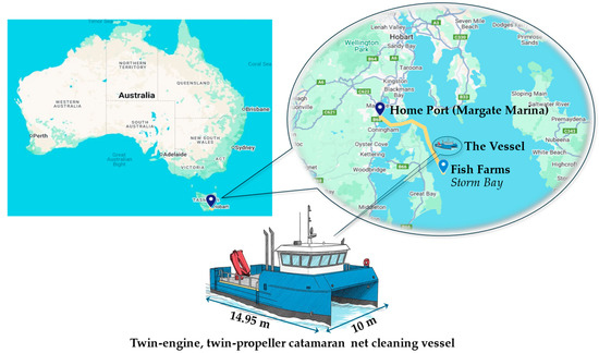
Figure 1.
Home port, service area, and the benchmark vessel.
The NCV’s main particulars are detailed in Table 1, while her power system parameters are provided in Table 2. The vessel completes one round trip per day, covering approximately 50 km per round trip, with operations conducted 355 days per year (assuming 10 days per year are required for inspection and maintenance).

Table 1.
Principal particulars of the benchmark vessel.
Table 2.
Power system parameters of the benchmark vessel.
Considering 2.7 h of transit and 9 h of net-cleaning operations per day, this setup results in an estimated annual CO2 emission of 966 t, highlighting its substantial environmental footprint. The estimation is presented in Appendix A.
2.2. Options for Hydrogen Utilisation
To isolate technology effects from naval architecture changes, the study retains the original arrangement and subdivision. The main engines have relatively high power outputs (882 kW in total). If hydrogen were used as a substitute for diesel, storage in CH2 tanks would require substantially more space [8], potentially leaving insufficient room onboard for the necessary hydrogen tanks. In contrast, the electricity generator sets have a total power output of 172 kW. If hydrogen were utilised exclusively for electricity generation, the required storage volume would be significantly reduced.
Considering these factors, this study evaluates two hydrogen utilisation options:
- Option (i): Both the main engines and generator sets are substituted by hydrogen-powered systems—PEMFCs or ICEs.
- Option (ii): Only the generator sets are substituted by hydrogen-powered systems—PEMFCs or ICEs (propulsion remains diesel in transit).
By comparing the results of these two strategies, the study aims to provide a clearer understanding of the feasibility of using hydrogen as a fuel for the benchmark vessel.
2.3. Methodology for Sizing Hydrogen Systems
The sizing of hydrogen-related systems—including storage tanks, PEMFCs, and ICEs—was performed through a sequential, demand-driven approach linking vessel power requirements to component specifications. The procedure comprises three main steps:
Step 1. Determining Hydrogen Energy Requirement: The total hydrogen consumption was estimated based on the vessel’s overall mechanical and electrical energy requirements, applying appropriate conversion efficiencies for each power system.
Step 2. Sizing Storage Tanks: The total hydrogen demand per voyage and bunkering interval defined the minimum storage capacity. Depending on the selected storage technology, the tank volume was calculated from the usable volumetric densities. Spatial, weight, and stability constraints from the benchmark vessel were incorporated to ensure feasible integration.
Step 3. Selection and Integration of Power Systems: The required rated power determined the number and capacity of PEMFC modules or engine units. The final arrangement was verified against the available compartment volume and layout to ensure adequate installation and safety clearance.
2.4. Methodology for Annualised Total Cost of Ownership
The TCO of a vessel’s power system comprises capital expenditure (CAPEX) and operational expenditure (OPEX). CAPEX primarily includes the initial investment in the power system, while OPEX mainly consists of fuel costs and component replacement costs, such as fuel cell and battery replacements. The analysis focuses on the cost differences between hydrogen and diesel systems; components common to both systems are excluded to avoid duplication and maintain a consistent basis for comparison.
2.4.1. Method
This study uses equivalent annualised TCO to analyse the economic performance of the power systems. The equivalent annual TCO is expressed by Equation (1), where the annualised CAPEX is expressed by Equation (2) [53,54], the annual OPEX is expressed by Equation (3). The annualised equipment replacement cost is expressed by Equation (4) [53,54].
where is the initial investment, including the main equipment in the power systems, is the discount rate and is the lifespan (years) of a vessel. The discount rates for vessels vary considerably depending on factors such as market demand, vessel type, and age. In this study, is set at 6% based on a recent report on offshore service vessels’ discount rate [55], while is taken as 25 years [56].
where
where is the present value of equipment, is the discount rate and is the lifespan (years) of a vessel. As abovementioned, is taken as 6%, is 25 years.
2.4.2. Data Inputs
Based on market research, this section presents cost data for conventional diesel power systems (for comparison with hydrogen systems), hydrogen power systems, and fuel costs.
- (1)
- Diesel Power System
The cost data for diesel power systems are as follows:
- Initial Investment: The capital cost for the main engines and generator sets is estimated at AUD 400/kW (equivalent to USD 262/kW, based on the 2024 average exchange rate of 1 AUD = 0.6556 USD [57]), with gearboxes included as part of the engine system. This estimate accounts for classification certification and logistics fees.
- Diesel Cost: This study adopts the 2024 average diesel retail price in Australia, which is AUD 1.91 (USD 1.25) per litre, equivalent to AUD 2.25 (USD 1.48) per kg (based on a diesel density of 0.85 kg/L) [58].
- (2)
- Hydrogen Power System
The cost data for hydrogen power systems are as follows:
- PEMFC: The US Department of Energy (DOE) evaluated the costs of 100 kW and 250 kW PEMFCs for land-based applications [59]. This power range is close to the power range of small-scale vessels. Hence, this paper relies on the conclusions drawn by the US DOE to assess the cost of marine PEMFC systems. Figure 2 provides the estimated 2024 costs of PEMFC systems and stacks using the inflation calculator by the Reserve Bank of Australia [60]. For PEMFC systems with a power output of 100–250 kW, the cost range is projected to be AUD 4433–8060 (USD 2906–5284) per kW, depending on the scale of production. As for PEMFC stacks, the cost range is estimated to be AUD 549–885 (USD 360–580) per kW, depending on the production scale. In this study, AUD 6064 (USD 3976) per kW and AUD 782 (USD 513) per kW are applied to the 200 kW PEMFC systems and stacks, respectively.
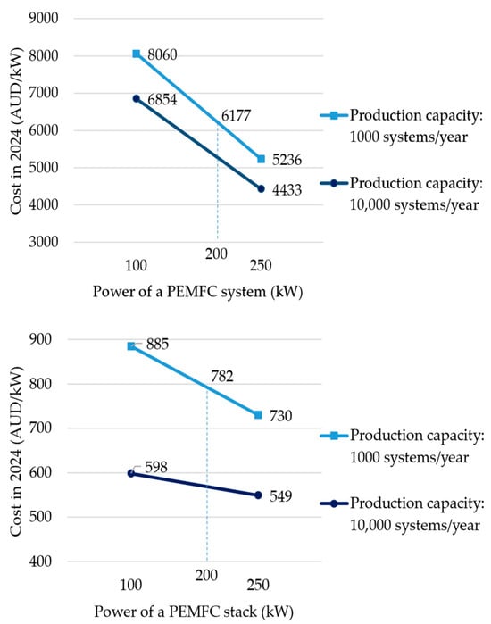 Figure 2. Costs of PEMFC systems and stacks in 2024.
 - Battery Packs: According to BloombergNEF, the cost of lithium-ion battery packs for electric vehicles fell to USD 115/kWh in 2024 [61]. For maritime applications, a cost factor of 1.5 is applied to account for classification society certification fees, resulting in an estimated cost of AUD 262/kWh (based on the 2024 average exchange rate), which is adopted in this study.
- Switchboard: The cost of a switchboard is estimated at AUD 10,000 (USD 6556) per unit, based on a manufacturer’s quotation.
- Replacement of PEMFC Stacks and Battery Packs: The balance-of-plant (BoP) in a PEMFC system is projected to have a service life of approximately 25 years, whereas the fuel cell stack is expected to operate for 24,000–30,000 h [62,63]. A recent European research project aims to demonstrate a maritime PEMFC with a target lifetime of 40,000 h [64]. Given the expected 25-year lifespan of a vessel [56], the BoP is unlikely to require replacement if properly maintained. By contrast, the fuel cell stack is expected to require one replacement during the vessel’s lifetime, assuming a total operating period of 40,000 h. The cycle life of lithium-ion batteries, defined as the number of charge and discharge cycles before performance degradation, is significantly influenced by the depth of discharge. Shallower discharge cycles extend battery life, while deeper discharge reduces it. For example, a battery discharged by 20% of its capacity has a significantly longer cycle life than one discharged by 80%. At a 50% depth of discharge, lithium-ion batteries are estimated to have a cycle life of approximately 8000 cycles [65]. On this basis, lithium-ion battery packs are also expected to require a single replacement over the vessel’s lifetime.
- (3)
- Hydrogen Storage System
The cost data for hydrogen storage systems are as follows:
- CH2 cylinders: In 2021, the US DOE evaluated the cost of 700 bar Type IV hydrogen cylinders for long haul trucks, which included integrated valves and regulators. Based on higher end of the cost range in US DOE’s report [66], this study estimated the 2024 cost of Type IV cylinder system for maritime use, as shown in Figure 3. The estimated cost range is AUD 1622–2408 (USD 1063–1579) per kg of hydrogen for 700 bar cylinders, accounting for a 1.5-fold increase to cover classification society certification fees. For subsequent analyses, a representative cost of AUD 1763 (USD 1156)/kg is adopted for 700 bar maritime Type IV cylinders.
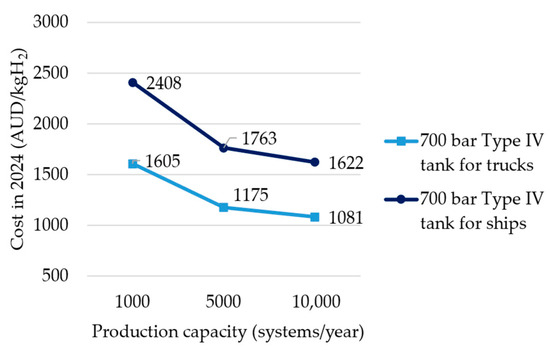 Figure 3. Costs of 700 bar Type IV compressed hydrogen cylinders in 2024.
- (4)
- Hydrogen Fuel
The cost data for hydrogen fuel are as follows:
- CH2 Fuel Bunkering Cost: According to the Hydrogen Vehicle Refuelling Infrastructure report published by Australian government scientific research agency CSIRO [67], the levelised cost of hydrogen dispensed by refuelling stations in Australia could range from AUD 6.78 to 15.60 (USD 4.44–10.23) per kg. Considering hydrogen production projects in Tasmania (see Section 3.3), this study adopts Configuration 1 from the CSIRO report (Figure 4). For this high-pressure refuelling scenario, with a maximum daily throughput of 500 kg, the estimated refuelling cost is AUD 11.96 (USD 7.84) per kg. In this study, hydrogen is supplied to the vessel via swap-and-go storage skids (see Section 3.2.3). The skids are refuelled at the dispenser (Figure 4) and transported by trailer from the refuelling station to the port. Based on the Australian road freight rate of AUD 0.09 (USD 0.06) per tonne-kilometre [68], a total skid weight of 2.1 t (see Section 3.2.3), and an assumed transport distance of 50 km, the additional logistics cost is estimated at AUD 0.07 (USD 0.05) per kg of hydrogen (see Section 3.2.2 for hydrogen tank parameters). Consequently, the total bunkering cost amounts to approximately AUD 12.03 (USD 7.89) per kg.
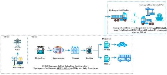 Figure 4. Cost estimate for hydrogen fuel bunkering.
3. Results and Discussion
This section integrates the sizing calculations, spatial constraints, and lifecycle economics to compare the two hydrogen utilisation options against the diesel baseline. The analysis proceeds in three steps. First, Option (i) (full substitution) evaluates engine room capacity and load sufficiency when both propulsion and ship-service demands are met using hydrogen. Second, Option (ii) (generator sets only) quantifies the space–mass trade-offs, annualised TCO, and CO2 abatement achievable with a single 200 kW PEMFC system, a 200-kWh battery buffer, and swap-and-go cylinder skids. In both cases, harmonised assumptions are applied. Feasibility is evaluated against three criteria: (i) sufficiency for one day of operation, (ii) compliance with safety regulations and rules, and (iii) comparative cost and emissions performance relative to the baseline.
3.1. Option (i): Replacing Main Engines and Generator Sets with Hydrogen Power Systems
This subsection analyses the feasibility of replacing the benchmark vessel’s diesel-powered main engines and generator sets with hydrogen fuel systems. It examines the applicability of hydrogen ICEs and PEMFCs for the vessel’s main propulsion and onboard power generation systems.
3.1.1. Main Propulsion
The energy conversion systems for the vessel’s main propulsion could be based on either PEMFCs or ICEs. However, given the relatively small size of the vessel, its high power demand, and the limited space available, the integration of currently available marine PEMFC systems and hydrogen-fuelled ICEs as substitutes for the diesel-fuelled main engines is not technically feasible:
- Currently, commercially available marine PEMFC systems are optimised to achieve a volume of 0.0072 m3/kW and a weight of 4.69 kg/kW (see Table 3). For the vessel’s required 882 kW of power, two PEMFC systems—together with two electric motors (1.23 m3 in volume and 4.13 t in weight)—would occupy a total volume of 7.58 m3 and weigh 8.34 t. When factoring in the additional volume and weight of energy storage batteries and distribution panels, the total size and weight would be even greater.
- Currently, only BEH2YDRO’s dual-fuel engine has received hydrogen engine certification from classification societies [69], making it the sole approved hydrogen ICE for marine use. Therefore, this study uses BEH2YDRO’s hydrogen-diesel dual-fuel 4-stroke ICE as the reference engine for the analysis. Table 4 presents BEH2YDRO’s 6DZD dual-fuel engine parameters [70]. The engine’s volume occupied is 11.8 m3, the dry mass is 10.62 t.
- By comparison, the vessel’s existing propulsion arrangement—comprising two diesel engines and gearboxes—occupies only 3.72 m3 with a total weight of 3.56 t. The maximum available space for the main propulsion equipment is 7.5 m3 (L 2.5 × W 1.5 × H 2.0 m).
Table 3.
Parameters of marine PEMFC systems.
Table 3.
Parameters of marine PEMFC systems.
| Maker | Nominal Output Power (kW) | Weight and Size | Note |
|---|---|---|---|
| Ballard | 200 | 1.0 t (5 kg/kW), L 1.209 × W 0.741 × H 2.195 m (1.97 m3, 0.0096 m3/kW) | The data was from reference [62] |
| Nedstack | 120 | 2.5 t (20.8 kg/kW), L 2.01 × W 1.10 × H 2.09 m (4.62 m3, 0.039 m3/kW) | The data was from reference [63] |
| Yanmar | 300 | 3 t (10 kg/kW), L 3.4 × W 1.1 × H 1.7 m (6.36 m3, 0.021 m3/kW) | The data was from reference [71] |
| PowerCell | 200 | 1.07 t (5.35 kg/kW), L 0.73 × W 0.9 × H 2.2 m (1.45 m3, 0.0073 m3/kW) | The data was from reference [72] |
| TECO 2030 | 325 | 1.525 t (4.69 kg/kW), L 1.38 × W 0.795 × H 2.125 m (2.33 m3, 0.0072 m3/kW) | The data was from reference [73] |
| VINSSEN | 2000 | 14 t (7 kg/kW), L 6 × W 2.5 × H 2.5 m (37.5 m3, 0.019 m3/kW) | The data was from reference [74] |
Table 4.
BEH2YDRO’s 6DZD dual-fuel engine parameters.
Table 4.
BEH2YDRO’s 6DZD dual-fuel engine parameters.
| Parameter | Value |
|---|---|
| Typical power range | 500–1000 kW |
| Dual fuel (gas) | H2 or less purified H2 on request |
| Pilot fuels | MDO/biodiesel |
| Volume occupied | 11.8 m3 |
| Dry mass | 10.62 t |
Note: the data was from reference [70].
Consequently, considering the available space of the engine rooms and the payload capacity of the vessel, this pronounced disparity underscores the impracticality of adopting PEMFCs or hydrogen ICEs for the current design.
3.1.2. Onboard Power Generation
During the operation of an NCV, the primary power-consuming equipment includes high-pressure water pumps and underwater ROVs. The benchmark vessel is equipped with two generator sets, each with a power output of 86 kW, providing a total power capacity of 172 kW when operating at full load.
If PEMFC systems were used to replace the diesel generator sets, based on an estimated volume of 0.0072 m3/kW and a weight of 4.69 kg/kW, the PEMFC systems would have a volume of 1.42 m3 and a weight of 0.928 t. By comparison, the two generator sets have a total volume of 4.24 m3 and a total weight of 2.058 t [75]. This analysis indicates that substituting the diesel generator sets with PEMFC systems would be feasible in terms of both engine room space and weight capacity.
PEMFC systems enable direct electricity generation, removing the intermediate step of converting mechanical energy to electrical energy required in diesel generator systems. This leads to improved power generation efficiency.
Currently, no marine hydrogen ICEs within this power range (approximately 100 kW) have been approved by classification societies. Consequently, the use of hydrogen generator sets as a replacement for diesel generator sets is not considered.
3.1.3. Summary for Option (i)
Based on the above analysis, the following summary can be drawn for Option (i):
- Given the small scale of the vessel and the relatively high-power output required by the main engines, the larger and heavier PEMFC systems and hydrogen-fuelled ICEs are not suitable as a replacement for the diesel main engines.
- For the diesel generator sets, which have a smaller power output, PEMFC systems are suitable replacements (see Section 3.2 for details). Moreover, the higher efficiency of PEMFCs in power generation highlights their advantages in this application.
- In conclusion, replacing both main engines and generator sets with hydrogen power systems is technically unfeasible.
3.2. Option (ii): Replacing Generator Sets with Hydrogen Power Systems
As indicated in the previous analysis, replacing the diesel generator sets with hydrogen-fuelled PEMFC systems is technically feasible. This section provides a detailed analysis of adopting PEMFC power generation systems.
3.2.1. Available PEMFC System
The benchmark vessel’s generator sets have a combined power output of 172 kW. This paper selects BALLARD 200 kW FCwave™ PEMFC to replace the diesel generator sets. The 200 kW FCwave™ PEMFC is one of the few marine fuel cell products on the market certified by classification societies and successfully deployed on multiple vessels [76]. The unit specifications are provided in Table 5.
Table 5.
BALLARD 200 kW FCwave™ PEMFC specifications.
3.2.2. Available Hydrogen Storage Tanks
This study incorporates commercially available CH2 storage cylinders to ensure practicality and alignment with current technological readiness. The technological development and commercialisation status of CH2 cylinders are well documented in the literature [78,79]. For the high-pressure CH2 cylinders, this study is based on the technical specifications of the Toyota G2L-2 700 bar type IV hydrogen cylinder (see Table 6) [80]. Type IV cylinders are entirely manufactured from the composite materials and a plastic liner, providing excellent strength-to-weight ratios and high-pressure capabilities [81]. It is worth noting that the Toyota G2L-2 hydrogen cylinders are currently the commercially available high-pressure hydrogen cylinder with the highest hydrogen storage density on the market.
Table 6.
Toyota G2L-2 700 bar type IV hydrogen storage cylinder specifications.
3.2.3. Hydrogen Storage Demand
Given the lower volumetric energy density of hydrogen compared to diesel, it is impractical to store an energy-equivalent amount of hydrogen onboard without altering the benchmark vessel’s size and layout. This study explores maximising hydrogen storage within the available space, focusing on the placement of hydrogen cylinders on the wheelhouse top deck, as both the IMO Interim Guidelines for Ships Using Hydrogen as Fuel and the classification society requirements recommend placing hydrogen cylinders on open decks [82,83]. For example, the IMO guidelines specify that “The fuel containment system and associated connections and equipment for compressed hydrogen should be located in an area on the open deck providing natural ventilation and unobstructed relief of leakages” [83]; the Bureau Veritas classification rules state that “Hydrogen fuel tanks are not to be installed in congested areas. Hydrogen fuel tanks and/or equipment located on open deck are to be located in order to ensure sufficient natural ventilation, so as to prevent accumulation of escaped hydrogen. A space naturally ventilated through with permanent side openings, having a combined area of at least 75% of the total side surface of the space, may be considered as an open deck for the purpose of the present requirement” [82].
As shown in Figure 5, the usable space beside the mast base on the wheelhouse top deck measures 4 m longitudinally, with a total width of 3.2 m (1.6 m on each side). By using TOYOTA G2L-2 hydrogen cylinders (1.85 m in length and 0.486 m in diameter) arranged in two vertical layers, this space can accommodate up to 24 cylinders. Each cylinder stores 8.2 kg of hydrogen, resulting in a total storage capacity of 196.8 kg.
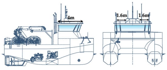
Figure 5.
Usable space on the wheelhouse top deck of the vessel.
The vessel performs net-cleaning tasks at the fish farm for 9 h per day, relying on the hydrogen PEMFC for power generation. A detailed calculation is provided in Table 7 to assess whether the available hydrogen can meet the vessel’s daily energy demands.
Table 7.
Hydrogen demand assessment.
The calculations in Table 7 demonstrate that the space in Figure 5 for hydrogen storage would be sufficient to support one day of operations. In this scenario, the vessel could refuel upon returning to port to prepare for the following day’s activities. To provide a storage margin of 15%, the study proposes equipping the vessel with 16 cylinders, resulting in a total onboard hydrogen storage capacity of 131.2 kg.
Each TOYOTA G2L-2 hydrogen cylinder weighs 118 kg, resulting in a total weight of 1.888 t for 16 cylinders. The design of the skids needs to comply with classification society rules [82], such as being designed with an open grating structure to meet natural ventilation requirements. As recommended by the IACS in its draft Recommendation for Use of Portable Tanks for Containment of Hydrogen Fuel onboard Ships, the design of the skids may comply with the Multiple-element Gas Containers (MEGC) requirements specified in the IMO International Maritime Dangerous Goods (IMDG) Code [84]. This design will increase the weight of the hydrogen storage system by approximately 10%, bringing the total weight of the two skids to around 2.1 t. As previously mentioned, these cylinders are arranged in the usable space on the wheelhouse top deck. This arrangement will impact on the vessel’s stability. Based on the vessel’s stability calculation book, the potential impact was preliminarily evaluated, indicating that adding 2.1 t of weight on the vessel’s roof would have an insignificant impact on stability. Across representative loading conditions, the estimated reduction in metacentric height (GM) is 4–6 cm, representing less than 1% of the original GM values.
3.2.4. Power Generation System Design
Figure 6 illustrates a simplified powertrain for the vessel, where hydrogen PEMFCs produce direct current (DC) electricity. The vessel uses a DC distribution system, with the PEMFC system connected to the DC bus via a DC-DC chopper to stabilise the bus voltage. The DC bus is then connected to an inverter, converting DC to alternating current (AC) electricity to power the onboard electrical grid.
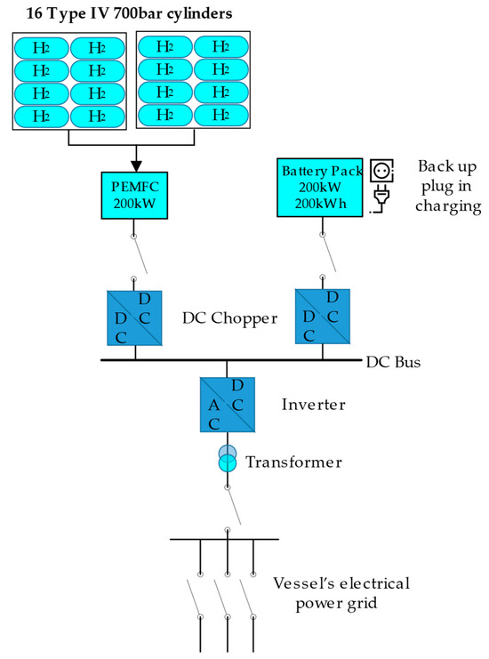
Figure 6.
PEMFC power generation system design for the vessel.
The system utilises the BALLARD 200 kW FCwave™ PEMFC. During net cleaning operations, the power system experiences load fluctuations. The PEMFC requires several minutes to adjust to sudden changes, which may hinder its ability to meet rapid load variations. Additionally, frequent changes in output power can adversely affect the fuel cell stack’s lifespan. To address these challenges, the PEMFC system is integrated with a lithium-ion battery pack to form a hybrid system.
When the vessel operates under low loads, excess electricity generated by the PEMFCs can be used to charge the battery pack. The battery pack has a maximum output power of 200 kW and a total storage capacity of 200 kWh, allowing for continuous operation at full power for one hour. It is also equipped with a backup plug-in charging port for recharging at the port when needed.
3.2.5. Size and Weight of the PEMFC System
The replacement of diesel generator sets with a hybrid power system requires the integration of a PEMFC unit, battery pack, and distribution board. Table 8 summarises a comparison of the dimensions and weights of the diesel generator sets and the hydrogen power system. The aim is to evaluate whether the existing auxiliary engine rooms can accommodate the PEMFC systems.
Table 8.
Size and weight comparison of diesel and hydrogen power systems.
As shown in the comparison, the hydrogen power system requires onboard space and weight comparable to those of the diesel generator sets, with slightly larger volume and heavier weight. The total volume of the hydrogen system is 2.8 m3, which is 8% larger than the combined volume of the two diesel generator sets at 2.6 m3. Its total weight is 2.4 t, 14% heavier than the diesel generator sets’ combined weight of 2.1 t. The auxiliary engine rooms of the benchmark vessel can accommodate the hydrogen power system. As the vessel is a catamaran, the distribution of weight and volume is considered by installing the BALLARD 200 kW FCwave™ PEMFC in the auxiliary engine room of one hull, while the battery pack and switchboard are installed in the auxiliary engine room of the other hull. This arrangement results in minimal deviation from the original volume and weight distribution of the benchmark vessel, requiring only minor modifications to the vessel’s design.
3.2.6. Vessel Arrangement
Based on the above analysis, the overall arrangement of the hydrogen storage and PEMFC power generation system is illustrated in Figure 7. Sixteen hydrogen cylinders are positioned on the top deck, while the port and starboard auxiliary engine rooms house the PEMFC system, battery pack, and switchboard, respectively.
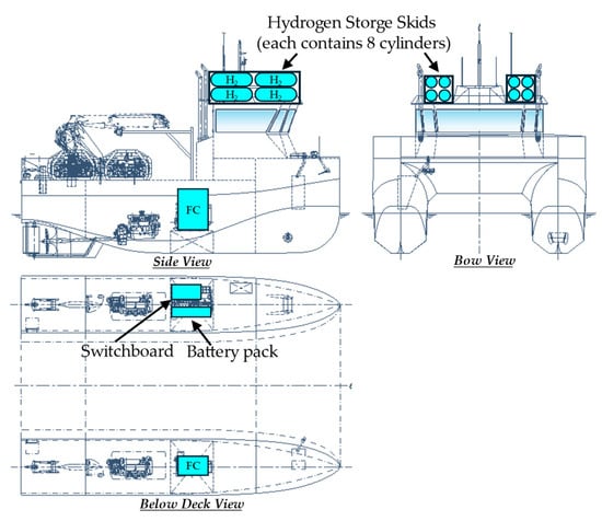
Figure 7.
PEMFC power generation system arrangements on the vessel.
Considering the use of cylinder replacement for refuelling, 16 hydrogen cylinders are designed into two skids, each containing eight cylinders. It is important to note that at least two additional skids will be required for replacement purposes, leading to increased costs.
The existing auxiliary engine rooms require modifications to comply with classification society regulations for fuel cell (FC) rooms. Unlike diesel engine rooms, FC rooms demand advanced ventilation systems to prevent the accumulation of hydrogen, which has a wide flammability range (4–75% in air), and must include hydrogen leakage detectors for real-time monitoring. Fire suppression in FC rooms typically involves inert gas systems to protect sensitive equipment, contrasting with the water-based or CO2 systems used in diesel engine rooms. Stringent explosion-proof standards must also be met, including specialised electrical equipment and controlled pressure differentials to prevent air intrusion.
The lithium-ion battery pack and switchboard are installed in the same compartment, with key safety considerations addressed. These include adequate physical separation to mitigate fire risks, effective ventilation, and robust fire suppression systems. Electromagnetic compatibility must also be ensured to prevent equipment interference, alongside controlled environmental conditions to protect both components. Compliance with international standards, like IEC 62,619 [85], and adherence to relevant classification society rules are essential to ensure safe and reliable operation.
3.2.7. Total Cost of Ownership
Figure 8 compares the annualised TCO of the vessel using diesel generator sets versus a hydrogen PEMFC power system. The annualised TCO for the diesel system is AUD 314,498 (USD 206,185), while for the hydrogen PEMFC system it is AUD 623,424 (USD 408,717), which is 98% higher. The annualised CAPEX for the diesel generator sets is significantly lower than that of the hydrogen system, at only AUD 5382 (USD 3528) compared to AUD 137,711 (USD 90,283) for the hydrogen system, which is about 24.59 times higher. In terms of annualised OPEX, the diesel system costs AUD 309,116 (USD 202,656), while the hydrogen system costs AUD 485,172 (USD 318,079), which is 57% higher.
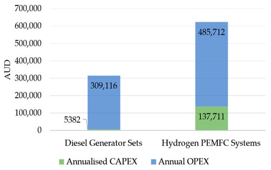
Figure 8.
Equivalent-annual TCO comparison: diesel generator sets vs. hydrogen PEMFC system.
3.2.8. CO2 Emissions Reduction
As calculated in Appendix A, the annual diesel consumption of diesel generator sets with a total power of 172 kW is 161,629 L (137,385 kg ÷ 0.85 kg/L). The CO2 emission factor for diesel is 2.68 kg CO2/L [86], resulting in an annual CO2 emission of 433 t from the diesel generator sets. Therefore, replacing the diesel generator sets with a zero CO2-emission hydrogen PEMFC power generation system can reduce CO2 emissions by 433 t per year, as shown in Figure 9. This is a significant contribution to the decarbonisation of the vessel.
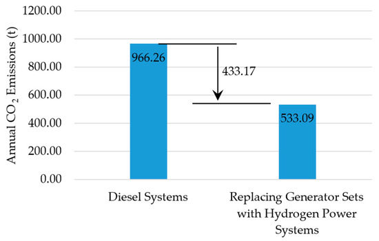
Figure 9.
CO2 emissions reduction from replacing diesel generator sets with a hydrogen PEMFC system.
3.2.9. Summary for Option (ii)
Based on the above analysis, the following summary can be drawn for Option (ii):
- Allowing for a reasonable margin, 16 high-pressure hydrogen cylinders (700 bar) with a total hydrogen storage capacity of 131.2 kg can meet the daily hydrogen demand of the vessel’s PEMFC power generation system. The 16 cylinders are arranged into two skids, each containing eight cylinders, and are placed on the vessel’s top deck. The total weight of the skids is approximately 2.1 t (1.888 t for the cylinders plus 10% for the skid structure). The additional weight would have an insignificant impact on the vessel’s stability.
- The onboard hydrogen fuel power generation system consists of a 200 kW PEMFC system, a lithium battery pack with a 200-kWh capacity and a maximum output power of 200 kW, and a distribution board. The PEMFC is located in the auxiliary engine room on one side of the vessel, while the battery pack and distribution board are located in the auxiliary engine room on the other side. The engine room dimensions, and load do not need to be modified, but the safety design of the engine room needs to be reconsidered according to the safety characteristics of hydrogen to meet classification society rules.
- The annualised TCO of the PEMFC power generation system is 1.98 times that of the original diesel generator sets.
- The CO2 reduction achieved with Option (ii) could reach 433 t per year.
3.3. Hydrogen Bunkering Availability
For hydrogen bunkering, given the current constraints in Australia’s hydrogen supply chain and bunkering availability [87], this study proposes a skid swap-and-go approach, whereby interchangeable fuel cylinder skids are replaced at the dock. At the early stage of hydrogen adoption, the use of swap-and-go storage skids enables hydrogen refuelling through existing stations located outside harbour areas, eliminating the immediate need for port-side infrastructure. This flexible approach can accelerate the uptake of hydrogen as a marine fuel. Examples include the vessels Hydro BINGO and Hanaria [8,88], both of which have adopted this refuelling method. By adopting this strategy, the challenges associated with hydrogen supply chain integration can be mitigated, offering a practical solution.
The home port of the NCV is in Hobart, Tasmania, where the Blue Economy Cooperative Research Centre (CRC)’s Hydrogen Production and Research Facility, launched in March 2025 (see Figure 10) [89], will produce 262 kg of green hydrogen per day—equivalent to approximately two days of the NCV’s hydrogen demand. The facility is located 28 km north of the home port.
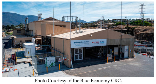
Figure 10.
The Blue Economy CRC’s hydrogen production and research facility in Tasmania.
A second hydrogen production project by Countrywide Hydrogen Pty Ltd. (Melbourne, Australia) is currently in development [90]. This project will use a 5 MW electrolyser with an expected capacity of 2.1 t of green hydrogen per day. The project will be located at the Brighton Transport Hub, 48 km north of the home port. The hydrogen produced will meet the quality requirements for use in PEMFCs [91].
The NCV will use two skids, as described in Section 3.2.3. These two skids can be transported between the hydrogen production plants and the home port using dedicated vehicles, with empty cylinders taken to the plants and full cylinders brought back to the home port. The skids will be replaced while the vessel is docked.
4. Conclusions
This study evaluated the feasibility of utilising hydrogen fuel for a 14.95 m NCV. The analysis explored two primary options: Option (i) involved replacing both the diesel-powered main propulsion system and the onboard power generation system with hydrogen-based systems, while Option (ii) focused solely on replacing the diesel generator sets with a hydrogen fuel system. The key conclusions from the study are as follows:
- For Option (i), the small scale of the vessel combined with the relatively high power demand of the main engines renders the larger and heavier PEMFC systems and hydrogen-fuelled ICEs unsuitable as replacements for the existing diesel main engines. By contrast, for the diesel generator sets, which require lower power output, PEMFC systems present a viable alternative, with their higher efficiency in power generation further underscoring their advantages in this role. Overall, the complete replacement of both main engines and generator sets with hydrogen power systems is deemed technically unfeasible under current spatial and technological constraints.
- For Option (ii), using a PEMFC system combined with a lithium battery pack to replace the original diesel generator sets would require minimal modifications to the existing auxiliary engine room compartment design in terms of equipment space and weight. For hydrogen storage, the vessel’s top deck could store the hydrogen needed for one day of operation of the power generation system. The hydrogen cylinders could be designed as skids, allowing for quick replacement while the vessel is docked. In summary, Option (ii) is technically feasible.
- The annualised TCO of the PEMFC system in Option (ii) is 1.98 times that of the diesel generator sets.
- The CO2 reduction effect of Option (ii) could reach 433 t per year, contributing to the decarbonisation of the Australian aquaculture and maritime industries.
This paper demonstrates the potential for hydrogen-based power systems to contribute to the decarbonisation of near-shore aquaculture vessels. While full substitution of diesel main engines remains technically infeasible for small vessels under current technological and spatial constraints, the integration of PEMFC systems for auxiliary power shows promise in terms of operational feasibility and emissions reduction. Nonetheless, several challenges remain. The relatively high cost of hydrogen systems, the limited volumetric energy density of CH2 storage, and the immaturity of bunkering infrastructure in Australia all present barriers to widespread adoption. Furthermore, the added complexity of integrating battery packs and hydrogen storage skids requires careful consideration of safety, certification, and long-term operational reliability. To accelerate the practical adoption of hydrogen in the maritime sector, government support—such as policies, subsidies, demonstration funding, and investment in bunkering infrastructure—will be essential to reduce the costs and risks associated with early implementation.
Future work should focus on high-efficiency hydrogen storage methods, detailed safety assessments, lifecycle cost analysis under varying cost scenarios, and pilot-scale demonstrations to validate technical feasibility in real-world operations.
This study is limited to the existing arrangement and subdivision of the reference vessel. Nonetheless, through a complete redesign—such as enlarging the hull, reinforcing the load-bearing capacity of local structures, and optimising seaworthiness—the constraints on adopting hydrogen systems onboard could be alleviated.
Author Contributions
Conceptualization, H.F., P.S.-L.C., A.H. and N.A.; methodology, H.F., P.S.-L.C., A.H., N.A. and E.M.A.G.; validation, H.F., P.S.-L.C., A.H., N.A., E.M.A.G., I.P. and J.A.M.; formal analysis, H.F., P.S.-L.C., A.H. and N.A.; resources, H.F., P.S.-L.C., A.H., N.A. and I.P.; data curation, H.F., P.S.-L.C. and A.H.; writing—original draft preparation, H.F.; writing—review and editing, P.S.-L.C., A.H., N.A., E.M.A.G., I.P. and J.A.M.; project administration, A.H., P.S.-L.C. and H.F. All authors have read and agreed to the published version of the manuscript.
Funding
This research was funded by the Blue Economy Cooperative Research Centre (CRC) under the project Hydrogen Powering of Vessels (Project No. 1.21.007).
Data Availability Statement
The original contributions presented in this study are included in the article. Further inquiries can be directed to the corresponding author.
Acknowledgments
The authors acknowledge the financial support of the Blue Economy Cooperative Research Centre (CRC), established and supported under the Australian Government’s CRC Program, grant number CRCXX000001 (previously 20180101). The authors also thank the research participants of the project Hydrogen Powering of Vessels.
Conflicts of Interest
Author Andrew Harris was employed by the company BMT. The remaining authors declare that the research was conducted in the absence of any commercial or financial relationships that could be construed as a potential conflict of interest.
Abbreviations
| AC | Alternating current |
| AFC | Alkaline fuel cell |
| AMSA | Australian Maritime Safety Authority |
| AUD | Australian dollars |
| BoP | Balance-of-plant |
| CAPEX | Capital expenditure |
| CH2 | Compressed hydrogen |
| CO2 | Carbon dioxide |
| CRC | Cooperative Research Centre |
| DC | Direct current |
| DOE | The US Department of Energy |
| FC | Fuel cell |
| FRDC | The Fisheries Research and Development Corporation, Australia |
| GHG | Greenhouse gas |
| GM | Metacentric height |
| H2 | Hydrogen |
| IACS | International Association of Classification Societies |
| ICE | Internal combustion engine |
| IEC | International Electrotechnical Commission |
| IMDG Code | International Maritime Dangerous Goods Code |
| LH2 | Cryogenic liquid hydrogen |
| MH | Metal hydride |
| NCV | Net cleaning vessel |
| OPEX | Operational expenditure |
| PEMFC | Proton exchange membrane fuel cell |
| ROV | Remotely operated underwater vehicle |
| SOFC | Solid oxide fuel cell |
| TCO | Total cost of ownership |
| USD | US dollars |
Appendix A. Annual CO2 Emissions Estimation for the Benchmark Net Cleaning Vessel
This appendix provides an estimation of the annual CO2 emissions for the net cleaning vessel. The vessel specifications and operational parameters are as follows:
- Main propulsion engine: 882 kW diesel engine
- Generator sets: 172 kW diesel generator sets
- Distance to offshore fish farms: 25 km
- Operating speed: 10 kt (18.52 km/h)
- Operation at the farm relies primarily on generator sets
- Operating days per year: 355
Transit phase:
- Speed: 10 kt (~18.52 km/h)
- Round trip distance: 50 km (2 × 25 km)
- Time for transit: 2.70 h (round trip)
- Fuel consumption (main propulsion engines):
- ∘
- Fuel/hour = 882 kW × 0.20 kg/kWh = 176.40 kg/h
- ∘
- Total fuel for transit = 176.40 kg/h × 2.70 h = 476.28 kg
Operations at the Farm:
- Assume operation time per day: 9 h
- Fuel consumption (generator sets):
- ∘
- Fuel/hour = 172 kW × 0.25 kg/kWh = 43.00 kg/h
- ∘
- Total fuel for operations/day = 43.00 kg/h × 9 h = 387.00 kg
Annual Operation:
- Annual fuel consumption for transit: Fuel for transit/year = 476.28 kg/trip × 355 trips = 169,078.05 kg
- Annual fuel consumption for farm operations: Fuel for operations/year = 387.00 kg/day × 355 days = 137,385.00 kg
Total CO2 Emissions:
- Total fuel consumption: Total fuel = 169,078.05 kg (transit) + 137,385.00 kg (operations) = 306,463.05 kg
- Convert to litres (diesel density = 0.85 kg/L): Total fuel (litres) = 306,463.05 kg ÷ 0.85 kg/L = 360,544.76 L
- CO2 emissions: CO2/year = 360,544.76 L × 2.68 kg CO2/L = 966,259.98 kg CO2/year
Conclusion:
- The net cleaning vessel emits approximately 966.26 t of CO2 annually.
References
- MacLeod, M.J.; Hasan, M.R.; Robb, D.H.F.; Mamun-Ur-Rashid, M. Quantifying greenhouse gas emissions from global aquaculture. Sci. Rep. 2020, 10, 11679. [Google Scholar] [CrossRef]
- Australian Government. Australia’s Aquaculture Industry. Available online: https://www.agriculture.gov.au/agriculture-land/fisheries/aquaculture/aquaculture-industry-in-australia (accessed on 1 August 2025).
- Boyer, A. Calculating Seafood’s Carbon Footprint. Available online: https://www.frdc.com.au/calculating-seafoods-carbon-footprint (accessed on 1 August 2025).
- Australian Government. Setting Our 2035 Target and Path to Net Zero. Available online: https://www.dcceew.gov.au/about/news/setting-2035-target-path-net-zero (accessed on 19 September 2025).
- Reese, L. Australia Announces a 2050 Net-Zero Emissions Target. Available online: https://ihsmarkit.com/research-analysis/australia-announces-a-2050-netzero-emissions-target.html (accessed on 14 June 2022).
- Button, J. Huon Aquaculture Net Cleaner Recruitment Video. Available online: https://www.youtube.com/watch?v=stlfL8jqU4w (accessed on 1 July 2025).
- Liu, H.; Jiang, C.; Chen, J.; Li, H.; Chen, Y. Research Advances in Marine Aquaculture Net-Cleaning Robots. Sensors 2024, 24, 7555. [Google Scholar] [CrossRef]
- Fan, H.; Abdussamie, N.; Chen, P.S.-L.; Harris, A.; Gray, E.M.; Arzaghi, E.; Bhaskar, P.; Mehr, J.A.; Penesis, I. Two decades of hydrogen-powered ships (2000–2024): Evolution, challenges, and future perspectives. Renew. Sustain. Energy Rev. 2025, 219, 115878. [Google Scholar] [CrossRef]
- Butler, J. Throwback Thursday: World’s 1st Hydrogen Boats. Available online: https://plugboats.com/throwback-thursday-worlds-1st-hydrogen-boats/ (accessed on 30 March 2023).
- Hydrogen House. Hydrogen Fuel Cell Duffy-Herreshoff Watertaxi. Available online: https://hydrogenhouseproject.org/duffy-herreshoff-watertaxi.html (accessed on 3 April 2023).
- Guan, W.; Chen, L.; Wang, Z.; Chen, J.; Ye, Q.; Fan, H. A 500 kW hydrogen fuel cell-powered vessel: From concept to sailing. Int. J. Hydrogen Energy 2024, 89, 1466–1481. [Google Scholar] [CrossRef]
- FPS. Request for a Recommendation on the Use of Hydrogen Fuel Cells for the Propulsion of the Vessel “FPS Waal”; Geneva, 21–25 August 2023. Available online: https://unece.org/transport/documents/2023/11/working-documents/netherlands-request-recommendation-use-hydrogen-0 (accessed on 10 May 2025).
- Wikipedia. Xperiance NX Hydrogen. Available online: https://en.wikipedia.org/wiki/Xperiance_NX_hydrogen (accessed on 7 June 2023).
- Boatsales. Yanmar Trials Real-World On-Water Hydrogen Refuelling. Available online: https://www.boatsales.com.au/editorial/details/yanmar-trials-real-world-on-water-hydrogen-refuelling-132531/ (accessed on 6 March 2023).
- Østvik, I. MF Hydra-World’s First LH 2 Driven Ship and the Challenges Ahead Towards Zero Emission Shipping; Norway, 2021. Available online: https://www.uib.no/sites/w3.uib.no/files/attachments/norled_mf_hydra_dec_2021.pdf (accessed on 4 May 2025).
- Cheetah Marine. World’s First Hydrogen Powered Boat Smashes Targets. Available online: https://www.cheetahmarine.co.uk/en/deliveries/worlds-first-hydrogen-powered-boat-smashes-targets (accessed on 1 March 2023).
- Moen Marin. Pilot-E–The World’s First Hydrogen-Powered Work Vessel. Available online: https://www.moenmarin.no/en/pilot-e-the-worlds-first-hydrogen-powered-work-vessel/ (accessed on 5 October 2025).
- McKinlay, C.J.; Turnock, S.R.; Hudson, D.A.; Manias, P. Hydrogen as a deep sea shipping fuel: Modelling the volume requirements. Int. J. Hydrogen Energy 2024, 69, 863–873. [Google Scholar] [CrossRef]
- Drube, T.K.; Gerlach, J.M.; Leach, T.S.; Vogel, B.; Klebanoff, L.E. Exploring variations in the weight, size and shape of liquid hydrogen tanks for zero-emission fuel-cell vessels. Int. J. Hydrogen Energy 2024, 80, 1441–1465. [Google Scholar] [CrossRef]
- Melideo, D.; Desideri, U. The use of hydrogen as alternative fuel for ship propulsion: A case study of full and partial retrofitting of roll-on/roll-off vessels for short distance routes. Int. J. Hydrogen Energy 2024, 50, 1045–1055. [Google Scholar] [CrossRef]
- Mäkelä, M.; Niemi, S.; Nuortila, C.; Nyystilä, L. Applicability of Hydrogen Fuel for a Cruise Ship. Clean Technol. 2025, 7, 6. [Google Scholar] [CrossRef]
- Bortnowska, M.; Zmuda, A. The Possibility of Using Hydrogen as a Green Alternative to Traditional Marine Fuels on an Offshore Vessel Serving Wind Farms. Energies 2024, 17, 5915. [Google Scholar] [CrossRef]
- Khan, M.W.Y.; Fan, H. Feasibility of Retrofitting a Conventional Vessel with Hydrogen Power Systems: A Case Study in Australia. Hydrogen 2025, 6, 11. [Google Scholar] [CrossRef]
- Brouzas, S.; Zadeh, M.; Lagemann, B. Essentials of hydrogen storage and power systems for green shipping. Int. J. Hydrogen Energy 2025, 100, 1543–1560. [Google Scholar] [CrossRef]
- Lázár, M.; Mihálik, I.; Brestovič, T.; Jasminská, N.; Tóth, L.; Dobáková, R.; Duda, F.; Kmeťová, Ľ.; Hudák, Š. A Newly Proposed Method for Hydrogen Storage in a Metal Hydride Storage Tank Intended for Maritime and Inland Shipping. J. Mar. Sci. Eng. 2023, 11, 1643. [Google Scholar] [CrossRef]
- Van Hoecke, L.; Laffineur, L.; Campe, R.; Perreault, P.; Verbruggen, S.W.; Lenaerts, S. Challenges in the use of hydrogen for maritime applications. Energy Environ. Sci. 2021, 14, 815–843. [Google Scholar] [CrossRef]
- Xu, H.; Zhang, Y.; Zhang, X. Towards efficient and safe hydrogen storage for green shipping: Progress on critical technical issues of material development and system construction. Int. J. Hydrogen Energy 2025, 167, 150913. [Google Scholar] [CrossRef]
- Di Micco, S.; Minutillo, M.; Forcina, A.; Cigolotti, V.; Perna, A. Feasibility analysis of an innovative naval on-board power-train system with hydrogen-based PEMFC technology. In Proceedings of the 76th Italian National Congress ATI (ATI 2021), Rome, Italy, 15–17 September 2021; p. 07009. [Google Scholar] [CrossRef]
- Letafat, A.; Rafiei, M.; Sheikh, M.; Afshari-Igder, M.; Banaei, M.; Boudjadar, J.; Khooban, M.H. Simultaneous energy management and optimal components sizing of a zero-emission ferry boat. J. Energy Storage 2020, 28, 101215. [Google Scholar] [CrossRef]
- Villalba-Herreros, A.; Gómez, M.R.; Morán, J.L.; Leo, T.J. Emissions and noise reduction on-board an oceanographic vessel thanks to the use of proton-exchange membrane fuel cells. Proc. Inst. Mech. Eng. Part M 2020, 234, 298–310. [Google Scholar] [CrossRef]
- Dolan, R.H.; Anderson, J.E.; Wallington, T.J. Outlook for ammonia as a sustainable transportation fuel. Sustain. Energy Fuels 2021, 5, 4830–4841. [Google Scholar] [CrossRef]
- Fragiacomo, P.; Piraino, F.; Genovese, M.; Corigliano, O.; De Lorenzo, G. Experimental Activities on a Hydrogen-Powered Solid Oxide Fuel Cell System and Guidelines for Its Implementation in Aviation and Maritime Sectors. Energies 2023, 16, 5671. [Google Scholar] [CrossRef]
- Gambini, M.; Guarnaccia, F.; Manno, M.; Vellini, M. Feasibility study of LOHC-SOFC systems under dynamic behavior for cargo ships compared to ammonia alternatives. Int. J. Hydrogen Energy 2024, 81, 81–92. [Google Scholar] [CrossRef]
- Dere, C. Hydrogen Fueled Engine Technology, Adaptation, and Application for Marine Engines. In Decarbonization of Maritime Transport; Zincir, B., Shukla, P.C., Agarwal, A.K., Eds.; Springer Nature: Singapore, 2023; pp. 45–63. [Google Scholar] [CrossRef]
- Bunce, M.; Seba, B.; Andreutti, R.; Yan, Z.; Peters, N. Development of a High Power, Low Emissions Heavy Duty Hydrogen Engine; SAE International: Warrendale, PA, USA, 2024. [Google Scholar] [CrossRef]
- Veldhuis, I.J.S.; Richardson, R.N.; Stone, H.B.J. Hydrogen-fuelled gas turbine-powered high-speed container ship: A technical and economic investigation. Nav. Archit. 2005, 108–116. Available online: https://www.researchgate.net/publication/287070108_Hydrogen-fuelled_gas_turbine-powered_high-speed_container_ship_A_technical_and_economic_investigation/citations (accessed on 4 May 2025).
- Alkhaledi, A.N.; Sampath, S.; Pilidis, P. Propulsion of a hydrogen-fuelled LH2 tanker ship. Int. J. Hydrogen Energy 2022, 47, 17407–17422. [Google Scholar] [CrossRef]
- Jiang, J.; Zou, L.; Liu, X.; Han, Z.; Wang, R. A two-level real-time energy management strategy incorporating load forecasting for hydrogen fuel cell-powered ships. Energy Convers. Manag. 2025, 341, 120032. [Google Scholar] [CrossRef]
- Jiang, J.; Zou, L.; Zhang, L.; Wang, H.; Wang, Y.; Liu, X.; Pang, S. A three-layer energy management system for hydrogen-powered ships combined instantaneous load forecasting. Electr. Power Syst. Res. 2025, 243, 111494. [Google Scholar] [CrossRef]
- Fan, A.; Liu, H.; Wu, P.; Yang, L.; Guan, C.; Li, T.; Bucknall, R.; Liu, Y. LSTM-augmented DRL for generalisable energy management of hydrogen-hybrid ship propulsion systems. eTransportation 2025, 25, 100442. [Google Scholar] [CrossRef]
- Lee, C.-Y.; Park, S.-K. Numerical Study on the Characteristics of Hydrogen Leakage, Diffusion and Ventilation in Ships. Energies 2025, 18, 448. [Google Scholar] [CrossRef]
- Soto, V.; Baalisampang, T.; Arzaghi, E.; Garaniya, V. Numerical modelling of hydrogen release and dispersion in under-deck compressed hydrogen storage of marine ships. Int. J. Hydrogen Energy 2024, 59, 1244–1256. [Google Scholar] [CrossRef]
- Li, G.; Zhang, H.; Li, S.; Zhang, C. Risk Assessment of Hydrogen Fuel System Leakage in Ships Based on Noisy-OR Gate Model Bayesian Network. J. Mar. Sci. Eng. 2025, 13, 523. [Google Scholar] [CrossRef]
- Fan, H.; Abdussamie, N.; Harris, A.; Chen, P.S.-L. Numerical investigation of hydrogen fuel tank skid leakage on a hydrogen-powered vessel. In Proceedings of the 43rd International Conference on Ocean, Offshore and Arctic Engineering (OMAE2024), Singapore, 9–14 June 2024. [Google Scholar] [CrossRef]
- Jeong, J.; Choi, M.; You, H.; Chang, D. Comparative risk assessment of gaseous and liquid hydrogen fuel gas supply systems for hydrogen-fueled vessels. J. Ocean. Eng. Sci. 2025, in press. [Google Scholar] [CrossRef]
- Guan, W.; Chen, J.; Chen, L.; Cao, J.; Fan, H. Safe Design of a Hydrogen-Powered Ship: CFD Simulation on Hydrogen Leakage in the Fuel Cell Room. J. Mar. Sci. Eng. 2023, 11, 651. [Google Scholar] [CrossRef]
- Choi, S.; Jeong, B. CFD simulation of gas dispersion at hydrogen bunkering station. J. Int. Marit. Saf. Environ. Aff. Shipp. 2023, 7, 2261350. [Google Scholar] [CrossRef]
- Depken, J.; Simon-Schultz, M.; Baetcke, L.; Ehlers, S. Comparing the safety of bunkering LH2 and LNG using quantitative risk assessment with a focus on ignition hazards. Int. J. Hydrogen Energy 2024, 83, 1243–1250. [Google Scholar] [CrossRef]
- Fan, H.; Xu, X.; Abdussamie, N.; Chen, P.S.-L.; Harris, A. Comparative study of LNG, liquid hydrogen, and liquid ammonia post-release evaporation and dispersion during bunkering. Int. J. Hydrogen Energy 2024, 65, 526–539. [Google Scholar] [CrossRef]
- Schiaroli, A.; Campari, A.; Paltrinieri, N.; Cozzani, V.; Ustolin, F. Consequence Analysis of a Bunkering Facility for Liquid Hydrogen Loading and Unloading. In Proceedings of the 43rd International Conference on Ocean, Offshore and Arctic Engineering (OMAE 2024), Singapore, 9–14 June 2024. [Google Scholar] [CrossRef]
- Australian Maritime Safety Authority. Vessel Classes and Service Categories. Available online: https://www.amsa.gov.au/vessels-operators/domestic-commercial-vessels/vessel-classes-and-service-categories (accessed on 8 August 2025).
- Sustainable Ships. Specific Fuel Consumption [g/kWh] for Marine Engines. Available online: https://www.sustainable-ships.org/stories/2022/sfc (accessed on 11 August 2025).
- Feenstra, M.; Monteiro, J.; van den Akker, J.T.; Abu-Zahra, M.R.M.; Gilling, E.; Goetheer, E. Ship-based carbon capture onboard of diesel or LNG-fuelled ships. Int. J. Greenh. Gas Control. 2019, 85, 1–10. [Google Scholar] [CrossRef]
- Chen, P.S.-L.; Fan, H.; Abdussamie, N. Evaluation of hydrogen shipping cost for potential trade routes. WMU J. Marit. Aff. 2025, 24, 315–338. [Google Scholar] [CrossRef]
- Snyder, J. Offshore Vessel Day Rates Slip As Market Softens. Available online: https://www.rivieramm.com/news-content-hub/news-content-hub/day-rates-slip-as-market-softens-85527#:~:text=Data%20from%20Clarksons%20Research%2C%20which,US$42%2C742%20in%20H1%202024 (accessed on 12 September 2025).
- Müller-Casseres, E.; Leblanc, F.; van den Berg, M.; Fragkos, P.; Dessens, O.; Naghash, H.; Draeger, R.; Le Gallic, T.; Tagomori, I.S.; Tsiropoulos, I.; et al. International shipping in a world below 2 °C. Nat. Clim. Change 2024, 14, 600–607. [Google Scholar] [CrossRef]
- Australian Taxation Office. Rates for Financial Year Ending 30 June 2024. Available online: https://www.ato.gov.au/tax-rates-and-codes/foreign-exchange-rates-annual-2024-financial-year (accessed on 7 October 2025).
- Road Genius. Fuel Cost Statistics in Australia. Available online: https://roadgenius.com.au/statistics/fuel-cost-australia/ (accessed on 11 August 2025).
- Battelle Memorial Institute. Manufacturing Cost Analysis of 100 and 250 kW Fuel Cell Systems for Primary Power and Combined Heat and Power Applications; US, 2016. Available online: https://www.energy.gov/eere/fuelcells/articles/manufacturing-cost-analysis-100-and-250-kw-fuel-cell-systems-primary-power (accessed on 30 May 2025).
- RBA. Inflation Calculator. Available online: https://www.rba.gov.au/calculator/ (accessed on 12 August 2025).
- BloombergNEF. Lithium-Ion Battery Pack Prices See Largest Drop Since 2017, Falling to $115 per Kilowatt-Hour: BloombergNEF. Available online: https://about.bnef.com/insights/commodities/lithium-ion-battery-pack-prices-see-largest-drop-since-2017-falling-to-115-per-kilowatt-hour-bloombergnef/#:~:text=New%20York%2C%20December%2010%2C%202024,research%20provider%20BloombergNEF%20(BNEF) (accessed on 12 August 2025).
- Ballard. Marine Makert Brochure May 2023. Available online: https://online.flippingbook.com/view/744848/ (accessed on 9 June 2023).
- Nedstack. PemGen MT-FCPI-120. Available online: https://nedstack.com/en/pemgen-solutions/maritime-power-installations/pemgen-mt-fcpi-120 (accessed on 9 June 2023).
- CORDIS. Reliable, efficient, Scalable and Lower Cost 1 MW-Scale PEMFC System for Maritime Applications. Available online: https://cordis.europa.eu/programme/id/HORIZON_HORIZON-JU-CLEANH2-2025-03-03 (accessed on 14 October 2025).
- Qadrdan, M.; Jenkins, N.; Wu, J. Chapter II-3-D-Smart Grid and Energy Storage. In McEvoy’s Handbook of Photovoltaics, 3rd ed.; Kalogirou, S.A., Ed.; Academic Press: Cambridge, MA, USA, 2018; pp. 915–928. [Google Scholar] [CrossRef]
- Houchins, C.; James, B.D.; Acevedo, Y. Hydrogen Storage Cost Analysis US. 2021. Available online: https://www.hydrogen.energy.gov/pdfs/review21/st100_james_2021_o.pdf (accessed on 1 March 2025).
- CSIRO. Hydrogen vehicle refuelling infrastructure: Priorities and opportunities for Australia; CSIRO: 2023. Available online: https://www.csiro.au/en/about/challenges-missions/hydrogen/hydrogen-vehicle-refuelling-infrastructure (accessed on 18 October 2025).
- Australian Government. Freight Rates in Australia. 2017. Available online: https://www.bitre.gov.au/sites/default/files/is_090.pdf (accessed on 18 October 2025).
- LR. LR Awards Type Approval to BeHydro for its Hydrogen Dual-Fuel Engine. Available online: https://www.lr.org/en/knowledge/press-room/press-listing/press-release/2023/lr-awards-type-approval-to-behydro-for-its-hydrogen-dual-fuel-engine/ (accessed on 10 July 2025).
- BEH2YDRO. 6 DZ(D) H2. Available online: https://www.behydro.com/engines/6-dzd-h2 (accessed on 11 August 2025).
- Yanmar. Yanmar to Commercialize Maritime Hydrogen Fuel Cell System to Decarbonize Ships. Available online: https://www.yanmar.com/global/marinecommercial/news/2023/08/01/127374.html (accessed on 29 August 2023).
- PowerCell Group. Industrial Ready Megawatt Fuel Cell Solutions. Available online: https://powercellgroup.com/segments/marine/#Product (accessed on 16 May 2024).
- TECO 2030. TECO 2030 Fremtidens Hurtigbåt Hydrogen. Available online: https://hrf.no/wp-content/uploads/2024/10/5-TECO2030_hurtigbatkonferansen-2024-10-17.pdf (accessed on 9 November 2024).
- VINSSEN. Marine Hydrogen Fuel Cell Technology; 2023. Available online: https://www.vinssen.com/en/data/file/brochure/2106084759_7AZ6slIP_af69d78a5680484a68def66e0faa42f71979fb40.pdf (accessed on 18 October 2025).
- CATERPILLAR. C4.4 Marine Generator Set. Available online: https://www.pon-cat.com/application/files/2015/3555/1503/LEHM5095-03.pdf (accessed on 5 May 2025).
- BALLARD. Fuel Cell Power Module for Marine Applications. Available online: https://www.ballard.com/wp-content/uploads/2024/11/FCwave_20241008.pdf (accessed on 6 May 2025).
- Qasem, N.A.A.; Abdulrahman, G.A.Q. A Recent Comprehensive Review of Fuel Cells: History, Types, and Applications. Int. J. Energy Res. 2024, 2024, 7271748. [Google Scholar] [CrossRef]
- Magliano, A.; Perez Carrera, C.; Pappalardo, C.M.; Guida, D.; Berardi, V.P. A Comprehensive Literature Review on Hydrogen Tanks: Storage, Safety, and Structural Integrity. Appl. Sci. 2024, 14, 9348. [Google Scholar] [CrossRef]
- Mukwanje, C.A.; Faik, A.; Nachtane, M. Current progress, challenges, and future prospects in composite cryogenic hydrogen storage tanks. Polym. Compos. 2025, 46, S48–S70. [Google Scholar] [CrossRef]
- Toyota. Toyota High-Pressure Hydrogen Tank. 2023. Available online: https://www.toyota.co.jp/fuelcells/en/pdf/pdf2_202303.pdf (accessed on 15 April 2025).
- AFP. What is a Hydrogen Tank & Tank-Types. Available online: https://www.addcomposites.com/post/what-is-a-hydrogen-tank-tank-types (accessed on 16 May 2023).
- BV. NR678 Hydrogen-Fuelled Ships; Bureau Veritas: Paris, France, 2023. [Google Scholar]
- IMO. Report of the Working Group on Development of Technical Provisions for Safety of Ships using Alternative Fuels; IMO: London, UK, 2025. [Google Scholar]
- IMO. The International Maritime Dangerous Goods (IMDG) Code; IMO: London, UK, 2020; Available online: https://www.dandybooksellers.com.au/acatalog/IMDG-Code-2024-Edition.html?srsltid=AfmBOoqB68ltjWw6Tub8nTY7dUn8eZfvHG_p01G1Dn1loBwX2WUA7GcO#tab-product_KO200E (accessed on 15 April 2025).
- IEC 62619:2022; Secondary Cells and Batteries Containing Alkaline or Other Non-Acid Electrolytes-Safety Requirements for Secondary Lithium Cells and Batteries, for Use in Industrial Applications. IEC: Geneva, Switzerland, 2022.
- D-Carbonize. What Is the Carbon Footprint of a Conventional Car? Available online: https://d-carbonize.eu/carbon-footprint/conventional-car/ (accessed on 12 August 2025).
- Chen, P.S.-L.; Fan, H.; Enshaei, H.; Zhang, W.; Shi, W.; Abdussamie, N.; Miwa, T.; Qu, Z.; Yang, Z. Opportunities and Challenges of Hydrogen Ports: An Empirical Study in Australia and Japan. Hydrogen 2024, 5, 436–458. [Google Scholar] [CrossRef]
- MOL. A White Egg Floating on the Sea—The Birth of Hydrogen Passenger Vessel “HANARIA”. Available online: https://www.mol-service.com/blog/hanaria (accessed on 8 October 2025).
- Blue Economy CRC. Green Hydrogen Will Be Produced for the First Time in Tasmania, Following Today’s Launch of the Blue Economy CRC’s Hydrogen Production and Research Facility. Available online: https://blueeconomycrc.com.au/green-hydrogen-facility-launch/# (accessed on 15 August 2025).
- CSIRO. Hydrogen Brighton Project. Available online: https://research.csiro.au/hyresource/hydrogen-brighton-project/ (accessed on 3 June 2025).
- ISO 14687:2025; Hydrogen Fuel Quality—Product Specification. ISO: Geneva, Switzerland, 2025.
Disclaimer/Publisher’s Note: The statements, opinions and data contained in all publications are solely those of the individual author(s) and contributor(s) and not of MDPI and/or the editor(s). MDPI and/or the editor(s) disclaim responsibility for any injury to people or property resulting from any ideas, methods, instructions or products referred to in the content. |
© 2025 by the authors. Licensee MDPI, Basel, Switzerland. This article is an open access article distributed under the terms and conditions of the Creative Commons Attribution (CC BY) license (https://creativecommons.org/licenses/by/4.0/).