Article

Parameter Optimization Design of MPC Controller in AUV Motion Control Based on Improved Black-Winged Kite Algorithm

State Key Laboratory of Integrated Optoelectronics, JLU Region, College of Electronic Science and Engineering, Jilin University, Changchun 130012, China
*
Author to whom correspondence should be addressed.
J. Mar. Sci. Eng. 2025, 13(10), 2018; https://doi.org/10.3390/jmse13102018
Submission received: 31 August 2025 / Revised: 26 September 2025 / Accepted: 16 October 2025 / Published: 21 October 2025
(This article belongs to the Special Issue Optimal Maneuvering and Control of Ships—2nd Edition)

Abstract

This study proposes an improved Black-winged Kite Algorithm (IBKA) for the parameter optimization of the Model Predictive Control (MPC) controller in Autonomous Underwater Vehicles (AUVs). To tackle the optimization challenges associated with the weight matrices and prediction horizon in the MPC controller, IBKA innovatively integrates the Lens Opposition-Based Learning (LOBL) strategy with the BKA. Specifically, after the migration behavior of BKA, the LOBL strategy is introduced to generate new individuals, and on this basis, the optimal individual is retained as the leader of the black-winged kite. In the experimental scenarios of AUV heading control and depth tracking, the optimization effect of the IBKA-MPC controller is evaluated. The results indicate that, in the heading control experiment, for the MPC controller optimized by IBKA, the Integral of Absolute Error (IAE) and Integral of Time-weighted Absolute Error (ITAE) of the heading angle decreased by a maximum of 6.29% and 18.24%, respectively, compared with the MPC controller under non-optimized parameters. In the depth tracking experiment, for the MPC controller optimized by IBKA, the IAE and ITAE of the depth decreased by 91.86% and 94.78%, respectively, compared with the MPC controller under non-optimized parameters. Meanwhile, through comparative experiments with four classical optimization algorithms, it is verified that the IBKA with the LOBL strategy introduced has a better optimization effect on the parameters of the MPC controller than classical optimization algorithms.

1. Introduction

Autonomous Underwater Vehicles (AUVs), as essential tools in fields such as marine resource exploration, environmental monitoring, and military reconnaissance, have their motion control performance directly determine the efficiency and reliability of mission execution. Both heading control and depth tracking are core aspects of AUV motion control. By adjusting the outputs of thrusters and rudders, an AUV can navigate steadily toward a predefined target. Considerable research efforts have recently been devoted by the academic community to the development and optimization of AUV motion controllers. These studies range from classical to modern control theory, with the objective of improving control accuracy and response speed.
Currently, common AUV motion controllers include technologies such as Proportional–Integral–Derivative (PID) control [1,2,3], robust control [4], Sliding Mode Control (SMC) [5,6], Linear Quadratic Regulator (LQR) [7,8,9], and Model Predictive Control (MPC) [10,11]. As an advanced control method, MPC predicts the future behavior of a system by establishing a mathematical model. Leveraging this predictive capability, MPC determines the optimal control input by solving a constrained optimization problem. MPC finds extensive application across various engineering fields. It outperforms classical controllers in almost all these applications [12], ranging from balancing walking robots [13], suspending crane loads [14], and cruise control for heavy-duty trucks [15,16], to controlling rotor speed and power in wind energy conversion systems [17], to path tracking for AUVs [18]. MPC offers significant advantages in robustness, accuracy, and convergence speed. Its robustness is ensured by explicitly accounting for system dynamics and operational constraints, which allows a reliable performance under model uncertainties and external disturbances. Accuracy is achieved through predictive optimization, where future system behavior is forecasted and control inputs are continuously adjusted to minimize tracking errors. In terms of convergence speed, MPC provides rapid and smooth responses by optimizing control actions over a prediction horizon, thereby facilitating fast trajectory tracking while maintaining system stability and constraint compliance. Extensive research and applications of MPC have been achieved in areas such as trajectory tracking, obstacle avoidance control, and path planning for AUVs. Isah A. Jimoh et al. [19] investigate positioning control of AUVs for docking under varying tidal currents using a velocity form linear parameter varying MPC. By exploiting the interdependence of AUV kinematic and dynamic models, the method avoids increased state dimension and estimator use. Simulations show it improves transient response and reduces sensitivity to time-varying disturbances compared to prior controllers. Hong et al. [20] proposed a controller combining state transformation MPC and SMC, which effectively improved the path tracking accuracy, enhanced tracking efficiency, and reduced optimization time for AUVs when performing underwater search tasks in complex marine disturbance environments. Hao et al. [21] developed an improved tube-based MPC for AUVs subject to bounded external disturbances, addressing the issue of maintaining the disturbed system within a tube-shaped region centered on the reference state trajectory and achieving robust control of the AUV system. Wang et al. [22] proposed an event-triggered MPC strategy for tracking and obstacle avoidance in multi-AUV formation systems with bounded disturbances, and designed an event-triggered control mechanism to reduce communication and computational burdens. Yao et al. [23] presented an improved control method combining MPC and SMC, which achieves path tracking and obstacle avoidance while effectively reducing the mean square error and saturation rate of rudder angles. Isah A. Jimoh et al. [24] investigates 3-D trajectory tracking and point stabilization of AUVs under ocean disturbances via velocity-form MPC, reformulating the model as an LPV system without augmentation. Simulations verify its effectiveness in offset-free control with low computation while ensuring stability. Yet, in practical applications, the performance of MPC controllers largely depends on parameter selection. Traditional parameter selection methods typically rely on experience or trial-and-error approaches, which often fail to ensure optimal control performance in complex environments. These methods are not only time-consuming but also require highly experienced experts. Additionally, when the controlled object changes, the weight parameters must be manually readjusted, thereby causing considerable inconvenience in engineering applications. Therefore, there is a pressing need to develop an MPC controller parameter optimization algorithm based on a heuristic function, and to construct a fitness function with adjustable coefficients to rapidly determine MPC controller parameters under varying control requirements.
In recent years, the academic community has conducted extensive research on parameter optimization for various controllers, employing common heuristic algorithms such as Genetic Algorithm (GA) [25,26,27,28], Particle Swarm Optimization (PSO) Algorithm [29,30,31,32,33], Grey Wolf Optimization (GWO) Algorithm [34,35], and Ant Colony Optimization (ACO) [36,37] for optimizing parameter design in controllers such as PID and LQR. Specifically, parameter optimization for PID controllers primarily focuses on the proportional, integral, and derivative coefficients. Xiong et al. [25] presented a fuzzy adaptive PID control method for AUVs aimed at achieving motion control. The improved GA was shown to effectively enhance path optimization quality by improving genetic operation mechanisms. It not only increased the convergence speed by 30% compared with traditional algorithms but also improved the smoothness index of planned paths by 25%, verifying the engineering applicability of the algorithm. Eltayeb et al. [26] employed GA to optimize the gain parameters of fractional-order PID controllers and standard PID controllers for nonlinear robotic arm systems, significantly enhancing system robustness and tracking accuracy. The simulation results demonstrated a significant reduction in the root mean squared error of relevant variables during trajectory tracking. Liu et al. [29] proposed an improved PSO algorithm, which was designed to reduce the occurrence of trapping in local optimal solutions by modifying the particle swarm inertia weight and was applied to PID adaptive parameterization. Arrieta et al. [38] investigated the pitch–roll angle control problem in quadrotor unmanned aerial vehicle systems using a multi-objective optimization approach that comprehensively incorporated weighted cost functions in the form of the Integral of Absolute Error (IAE) and the Integral of Time-weighted Absolute Error (ITAE), as well as battery usage. Unlike PID controller optimization, parameter optimization for LQR controllers is primarily concerned with weight matrices Q and R . Fan et al. [27] proposed an improved quantum GA optimization method aimed at minimizing trajectory tracking error, which employed an improved quantum GA to jointly optimize the LQR state and control weight matrices Q and R , thereby deriving the optimal control law. Zhang et al. [30] introduced a PSO algorithm to optimize LQR controller parameters, which reduced the stabilization time of the two-dimensional ball-and-beam system and enhanced vibration frequency performance. Zhu et al. [31] proposed an autonomous optimization control method based on an improved PSO algorithm for controlling the Flexible Linear Double Inverted Pendulum, thereby improving the system’s performance. He et al. [33] proposed a Jumping Weight PSO algorithm, validated its optimization effectiveness using standard fitness functions, and applied it to the optimization of the weight coefficient matrices of the LQR controller, thereby effectively reducing horizontal vibrations in high-speed elevator cars. Xiong et al. [35] developed an improved LQR control strategy based on the GWO; compared with passive suspensions, the proposed controller significantly reduced vehicle body acceleration, and its control effect was superior to that of the traditional LQR controller. Manna et al. [36] proposed a new ACO algorithm for multi-objective weight optimization of the LQR in automotive active suspension systems. Yuvapriya et al. [39] proposed an optimal LQR method employing the Bat Algorithm to determine the state and input penalty matrices. The conflicting control objectives of the active suspension system were formulated as a multi-constraint optimization problem. Zhang et al. [40] introduced the differential evolution algorithm to optimize the weighted matrices of LQR. By adopting a real-number coding strategy for the weighted matrices Q and R , the optimal weighted matrices and feedback matrix K were obtained, with significant improvements in the system’s settling time and overshoot. Ata et al. [41] developed LQR controllers using four optimization algorithms to optimize the weighting matrices for tracking predefined three-dimensional trajectories. The optimization was limited to the weighting matrices Q and R without a well-defined fitness function or a detailed analysis of the optimization process. Compared with PID and LQR controllers, MPC controllers are more complex because they require consideration of a larger set of parameters during the design process. Nevertheless, relatively few optimization methods for MPC parameter design have been reported in the literature. Ma et al. [28] proposed a GA-MPC-based flexible power allocation system incorporating a hybrid ARIMA–LSTM predictor. Its main advantage lies in balancing ultracapacitor use and reducing battery throughput via real-time weight and constraint optimization, thereby improving efficiency and extending battery life. Li et al. [32] proposed a trajectory tracking control method for unmanned vehicles based on PSO, where the ITAE of lateral deviation and yaw rate deviation was used as the objective function for iterative optimization. The maximum longitudinal error of the MPC controller after weight matrix parameter optimization was significantly reduced. Li et al. [42] introduced a novel learning method based on the Butterfly Optimization Algorithm (BOA) to efficiently determine optimal MPC weights. Compared with LQR and pure pursuit strategies, the BOA-based method demonstrated superior control accuracy and stability. Nevertheless, the specific parameters optimized by BOA were not explicitly detailed in their study. Qiu et al. [43] proposed an Adaptive PSO-MPC method for plunger lift optimization, which increased daily natural gas production by 18% while ensuring effective liquid drainage and safe plunger ascent speed. Sun et al. [44] developed a two-step optimization method for freight train speed profiles: first optimizing the speed profile using a rolling optimization algorithm, then using the optimized profile as a reference curve for secondary optimization by the MPC controller. However, the study did not address optimization of MPC controller parameters, focusing instead on optimizing the curve itself. In summary, research on parameter optimization for PID and LQR controllers is relatively mature, whereas parameter optimization for the more complex MPC controller has received less attention. Moreover, existing studies are limited by unclear optimization mechanisms, resulting in ambiguities in optimized MPC controller parameters and incomplete formulations of fitness functions. Therefore, this paper will consider the motion mathematical model of the AUV as the controlled system and employ the novel intelligent optimization algorithm, the Black-winged Kite Algorithm (BKA), to propose a new approach for MPC controller parameter optimization. The main contributions of this research are as follows:
(1)
An innovative, improved Black-winged Kite Algorithm (IBKA) is proposed for the parameter optimization of MPC controllers. This method incorporates the Lens Opposition-Based Learning (LOBL) strategy into the BKA. By means of the fitness function, we integrate IBKA with the MPC controller, thereby achieving the parameter optimization of the MPC controller. IBKA enhances the efficiency of controller parameter optimization and offers a new approach for parameter selection in MPC controllers.
(2)
Starting from the control performance requirements of the AUV motion system, a fitness function with multi-dimensional optimization objectives is constructed, and the coefficients of each dimension in the function can be flexibly adjusted. By means of the given coefficients, this function quantifies the weights of different performance indicators, which effectively optimizes the selection process of MPC parameters and enhances the targeting and efficiency of controller parameter optimization.
(3)
The weight matrices Q , R and the prediction horizon N p are innovatively introduced into the scope of MPC controller parameter optimization, thereby broadening the dimensions of parameter optimization. Through the collaborative optimization of these core parameters, the dynamic control performance of the AUV controller under the same working conditions is further improved.
The remainder of this paper is organized as follows. The second part describes the mathematical model of AUV motion and the optimization mechanism of the BKA. The third part details the principles and methodology of MPC controller design using parameter optimization through IBKA. The fourth part, based on the IBKA-MPC controller, presents experiments on AUV heading control and depth tracking to validate the effectiveness of IBKA in optimizing MPC controller parameters. The fifth part provides the conclusions and outlines future research directions.

2. Motion Modeling and Optimization Mechanism

2.1. Mathematical Model of AUV Motion

To investigate the motion attitude and control of AUVs during course-keeping and diving processes, it is first necessary to establish a dynamic model of the underwater vehicle. Therefore, it is required to analyze the motion characteristics of the AUV, decouple and linearize the existing six-degree-of-freedom (6-DOF) model of the AUV, and then, respectively, derive the motion models for horizontal plane motion and vertical plane motion. When analyzing the motion and force conditions of the AUV under 6-DOF, it is necessary to establish both a ground coordinate system and a hull coordinate system. This paper adopts the terminology used by the Society of Naval Architects and Marine Engineers as recommended by the International Towing Tank Conference. The following two right-handed rectangular coordinate systems are used, as shown in Figure 1. o x y z is the hull coordinate system, which moves with the hull and is also called the moving coordinate system. The origin o is taken at the center of mass of the AUV. The x -axis is parallel to the roll axis of the AUV and points to the bow. The y -axis is consistent with the pitch axis and points to the starboard direction. The z -axis points to the bottom of the robot. o x y z is the ground coordinate system, also called the static coordinate system. The North-East-Down reference frame is fixed on the ocean surface. The origin o can be taken at any point on the ground or the sea surface. The x -axis points to the initial motion direction of the robot in the still water plane. The y -axis is in the same plane as the x-axis and is perpendicular to the x -axis. The z -axis is perpendicular to the still water surface, and the positive direction is defined to point to the center of the Earth.
The nonlinear motion equations of an AUV can be expressed in both the hull coordinate system and the ground coordinate system. In this research, the AUV is treated as a rigid body with uniformly distributed mass. Using the principles of hydrodynamics, the 6-DOF motion equations of the AUV within the coordinate systems can be derived. This study uses the NPS AUV II. Before the MPC controller is designed, its nonlinear motion equations must first be linearized. The linear motion state equations for the horizontal and vertical planes of the AUV are obtained by linearizing the 6-DOF nonlinear motion equations (including the surge, sway, heave, pitch, roll, and yaw motion equations) in the neighborhood of the equilibrium position [45,46,47]. The linearization derivation process assumes no external disturbances. During the linearization of the AUV’s horizontal plane motion equation, only sway motion and yaw motion are considered. After simplifications, the continuous-time linear state-space Equation (1) is obtained:
v ˙ r ˙ ψ ˙ = a h 11 a h 12 0 a h 21 a h 22 0 0 1 0 v r ψ + b h 11 b h 21 0 δ v ,
where v represents the sway velocity, r represents the yaw angular velocity, ψ represents the yaw angle, and δ v represents the vertical rudder angle. a h i j and b h i j denote coefficients in the horizontal plane motion model. a h i j depends on sailing speed, mass, inertia moments, and hydrodynamic coefficients, whereas b h i j depends on sailing speed, geometric characteristics, and rudder position.
During the linearization of the vertical plane motion equation, only heave and pitch motions are considered. After simplification and introducing η ˙ = w + u θ for navigation depth, the linear state-space Equation (2) is derived, incorporating navigation depth as a state variable.
w ˙ q ˙ θ ˙ η ˙ = a v 11 a v 12 a v 13 0 a v 21 a v 22 a v 23 0 0 1 0 0 1 0 u 0 w q θ η + b v 11 b v 12 0 0 δ h
where w represents the heave velocity, q represents the pitch angular velocity, θ represents the pitch angle, η represents the depth, u represents the surge velocity, and δ h represents the horizontal rudder angle. a v i j and b v i j denote coefficients in the vertical plane motion model. a v i j depends on sailing speed, mass, inertia moments, and hydrodynamic coefficients, whereas b v i j depends on sailing speed, geometric characteristics, and rudder position.

2.2. The Optimization Mechanism of the BKA

In recent years, meta-heuristic algorithms have rapidly developed and been widely applied, showing strong advantages in solving complex problems. Their design draws inspiration from biological behaviors, human and social activities, evolutionary mechanisms, and physical or chemical principles, forming an innovative and practical framework. This forms an algorithmic design framework that is both innovative and practical. The BKA is a new type of intelligent optimization algorithm inspired by the flight behaviors of black kites during predation. By simulating behaviors such as circling, diving, and preying of black kites, the algorithm can quickly find the optimal solution in the search space. Compared with traditional optimization algorithms, BKA offers advantages such as fast convergence speed, strong global search capability, and high robustness, making it particularly suitable for high-dimensional, nonlinear optimization problems [48]. In recent years, BKA has been widely applied in fields such as function optimization, engineering design, and control system optimization, demonstrating excellent performance [49,50]. The optimization process of the BKA includes population initialization, attack behavior, and migration behavior, with its pseudocode detailed in Algorithm 1.
Algorithm 1 Implementation of Traditional Black-winged Kite Algorithm
Input:   The   population   size   p o p ,   maximum   number   of   iterations   m a x g e n , variable dimension d i m ,   upper   bound   B K u b   and   lower   bound   B K l b of the variable.
Output:   The   optimal   solution   X best   and   the   best   fitness   F i t n e s s best obtained by BKA for a given optimization problem.
1: Initialization phase
2: Initialize the position of BKs within the upper and lower range of positions
3: Calculate the fitness value of each BK
4: while   t < m a x g e n  do
5:  /* Attacking behavior */
6:  if   s < r a n d  then
7:   y t + 1 p , q = y t p , q + n × 1 + sin r a n d × y t p , q
8:  else if do then
9:   y t + 1 p , q = y t p , q + n × 2 r a n d 1 × y t p , q
10:  end if
11:  /* Migration behavior */
12:  if   F i t n e s s p < F i t n e s s r p  then
13:   y t + 1 p , q = y t p , q + C 0 , 1 × y t p , q L t q
14:  else if do then
15:   y t + 1 p , q = y t p , q + C 0 , 1 × L t q m × y t p , q
16:  end if
17:  /* Select the best individual */
18:  if   y t + 1 p , q < L t q  then
19:    X best = y t + 1 p , q F i t n e s s best = f y t + 1 p , q
20:  else if do then
21:   X best = L t q F i t n e s s best = f L t q
22:  end if
23: end while
24: Return   the   best   individual   X best   and   the   best   fitness   F i t n e s s best

2.2.1. Population Initialization

In the operation of the BKA, population initialization is performed first, where creating a set of random solutions constitutes the initial step. When generating random solutions, the constraint conditions of the actual problem must be considered simultaneously. Specifically, the lower bound B K l b and upper bound B K u b for the positions of the black kites are defined, and Equation (3) is used to determine the required number of random solution groups. Since the position of each black kite B K in the search space corresponds to a feasible solution, the position of each black kite can be represented by the following matrix (4):
X p = B K l b + r a n d B K u b B K l b ,
B K = B K 1 , 1 B K 1 , 2 B K 1 , dim B K 2 , 1 B K 2 , 2 B K 2 , dim B K N , 1 B K N , 2 B K N , dim ,
where X p represents the solution of the p - th black kite. In the initialized population, the solutions are randomly generated by Equation (3). r a n d denotes a random value within the range 0 , 1 , N represents the number of potential solutions, and d i m represents the dimension size of the solution for a given problem. B K p , q is the solution of the q - th dimension for the p - th black kite, where p ranges from 1 , N and q ranges from 1 , d i m .
During the population initialization process, the BKA selects the black kite individual X L , which has the optimal fitness function value from the initialized population, to serve as the leader. If the minimum fitness function value is regarded as the optimal solution in the research, the expression can be presented as shown in Equation (5). Within the initialized population, the individual corresponding to the minimum fitness function value f best is identified, and this individual X best is designated as the leader. Meanwhile, the position of the leader is considered the best habitat for the black kites. The mathematical expression for the initial leader X L generated by the initial population, is given as Equation (6):
f best = min f X p ,
X L = X f i n d f best = = f X p ,
where f best represents the optimal fitness, calculated by substituting an individual into the fitness function. X p denotes the solution of the p - th black kite, while X L represents the leader of the population.

2.2.2. Attack Behavior

This section describes the attack behavior of the black kite from a bionic perspective to better understand the bionic principles of the BKA. The core of this behavior lies in hovering flight and precise capture. Black kites exhibit various attack behaviors for global exploration and prey searching. The mathematical expression for the attack process is shown in Equation (7), and the calculation process for the coefficients is presented in Equation (8). During combat, the angles of the black kites’ wings and tail feathers are adjusted according to wind speed, as they silently circle to observe prey. Once a target prey is locked, the black kite quickly dives to launch an attack.
y t + 1 p , q = y t p , q + n × 1 + sin r a n d × y t p , q s < r a n d y t p , q + n × 2 r a n d 1 × y t p , q e l s e ,
n = 0.05 × e 2 × t T 2 ,
where y t p , q and y t + 1 p , q represent the values of the q - th dimensional solution of the p - th black kite in the t - th and t + 1 - th iterations, respectively, and s is a constant. t represents the number of iterations completed so far, and T represents the maximum number of iterations.

2.2.3. Migration Behavior

The migration of Black-winged Kites is guided by population leaders. Inspired by this, the algorithm introduces a strategy for population optimization: when the leader reaches a local optimum, migration is used to seek the global optimum. If a randomly generated individual has higher fitness than the leader, the leader steps down, joins the migration group, and the new individual becomes the leader. Otherwise, the leader continues. This dynamic mechanism ensures effective migration and better optimization, with the mathematical model shown in Equation (9), while Equation (10).
y t + 1 p , q = y t p , q + C 0 , 1 × y t p , q L t q F i t n e s s p < F i t n e s s r p y t p , q + C 0 , 1 × L t q m × y t p , q e l s e ,
m = 2 × sin r a n d + π / 2 ,
where L t q represents the leading scorer among black kites in the q - th dimension during the current iteration cycle t . y t p , q and y t + 1 p , q denote the values of the q - th dimensional solution for the p - th black kite in the t - th and t + 1 - th iterations, respectively. C 0 , 1 represents the Cauchy mutation. F i t n e s s p represents the fitness value of any black kite individual in the t - th iteration cycle. F i t n e s s r p represents the fitness value of a randomly selected black kite individual in the t - th iteration cycle.

3. Design of the IBKA-MPC Controller

3.1. Basic Principles and Design of MPC Controllers

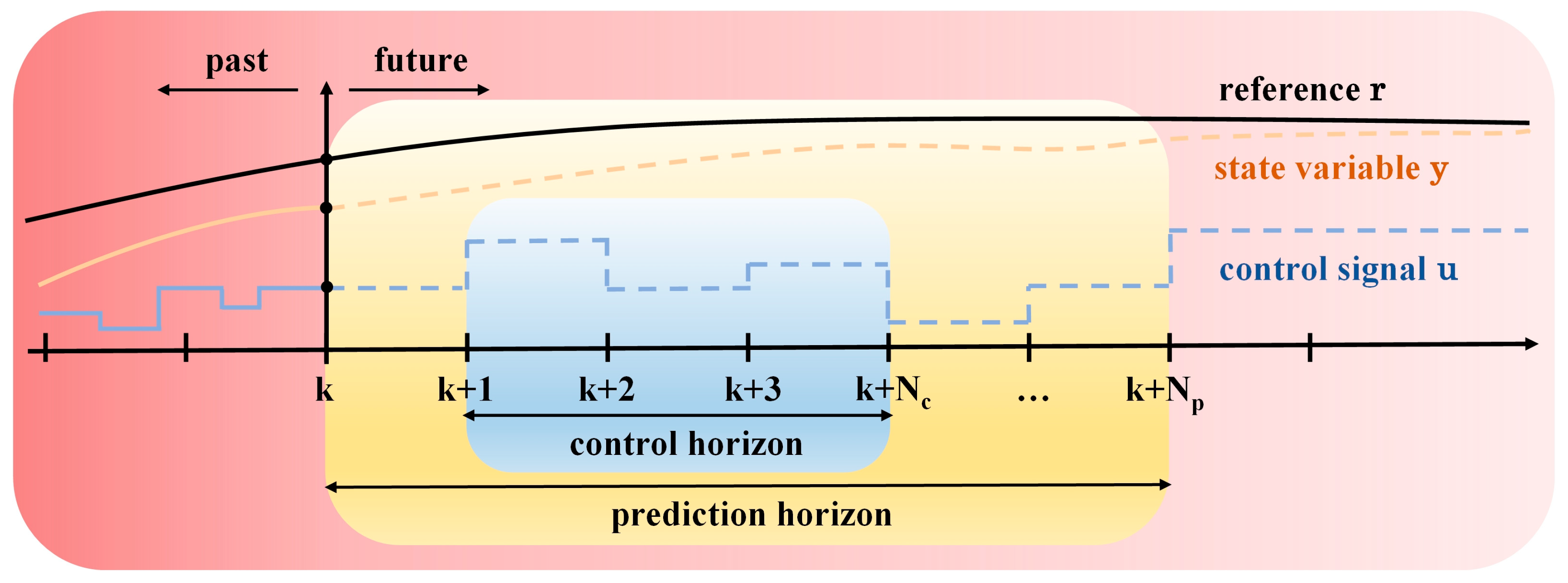
MPC is a class of advanced control methods that utilize process models to predict the future behavior of a controlled system. Leveraging this predictive capability, MPC determines the optimal control input u by solving a constrained optimization problem. As one of the few control methods that directly account for system constraints, MPC typically employs a specific form of cost function construction. It calculates N p time steps within the prediction horizon, enabling the system output y t to continuously track a given reference value r t over N c time steps in the control horizon. Figure 2 illustrates the basic principle of MPC. To achieve the parameter optimization of the MPC controller based on IBKA, it is first necessary to design MPC controllers separately according to the mathematical motion equations of the AUV, specifically the horizontal plane motion Equation (1) and the vertical plane motion Equation (2). For the mathematical motion model of the AUV proposed in Section 2.1, the MPC controller is used here to implement the heading control and depth tracking of the AUV, thereby verifying the effect of the IBKA on the parameter optimization of the MPC controller through specific examples. When implementing the motion control of the AUV using MPC, the continuous systems of Equations (1) and (2) need to be discretized into the form of Equation (11).
x k + 1 k = A x k + B u ¯ k y k + 1 k = C x k + D u ¯ k ,
where x denotes the state vector, u ¯ denotes the input vector, y denotes the output vector, and k denotes the current time step. A , B , C , and D represent the corresponding coefficient matrices, respectively.
Based on the state equation of the AUV’s motion mathematical model, it is assumed that the state variable x k of the AUV motion can be measured at time k . By deriving the state equation, the predicted state variable x ^ k + 1 k can be obtained, and its calculation Formula (12) can be generalized as Formula (13):
x ^ k + 1 k = A x k + B u ¯ k x ^ k + 2 k = A x ^ k + 1 k + B u ¯ k + 1 k = A 2 x k + A B u ¯ k + B u ¯ k + 1 k x ^ k + N p k = A N p x k + A N p 1 B u ¯ k + A N p 2 B u ¯ k + 1 k + + A B u ¯ k + N p 2 k + B u ¯ k + N p 1 k = A N p x k c + j = 0 N p 1 A N p 1 i B u ¯ k + i k ,
X ^ k = G x k + Γ U k ,
subject to
X ^ k = x ^ k + 1 k x ^ k + 2 k x ^ k + N p k T ,
U k = u ¯ k + 1 k u ¯ k + 2 k u ¯ k + N p 1 k T ,
G = A A 2 A N p T ,
Γ = B 0 0 A B B 0 A N p 1 B A N p 2 B B ,
where N p represents the prediction horizon, i ranges from 0 , 1 , , N p 1 . x ^ k + N p k represents the state variable at time k + N p predicted at the current time k , while u ¯ k + i k denotes the control input at time k + i predicted at the current time k . X ^ k denotes the state variable of the AUV at each prediction time step, and U k is the corresponding input control quantity. G and Γ are the augmented coefficient matrices. Through formula (14), the state sequence X ^ k can be predicted, and the control sequence U k within the prediction range can be obtained.
After constructing the discrete state-space equation of the system, the optimal control input of the MPC controller can be determined by setting a minimization objective function. Specifically, consider the optimization problem in Equation (18):
min u ¯ j = 1 N p x ^ k + j k T Q x ^ k + j k + u ¯ k + j 1 k T R u ¯ k + j 1 k ,
subject to
x ^ k + j + 1 k = A x ^ k + j k + B u ¯ k + j k ,
x min x ^ k + j k x max ,
u ¯ min u ¯ k + j 1 k u ¯ max ,
where j ranges from 0 , 1 , , N p 1 . Equation (19) represents the nominal system dynamic equation used to predict future states. Equations (20) and (21) represent the constraints for the system state variables and input controls, respectively. x max and x min represent the maximum and minimum values of the state variables, while u ¯ max and u ¯ min represent the maximum and minimum values of the control inputs. Q and R are the corresponding weighting matrices used for shaping the response, where Q is a positive semi-definite matrix and R is a positive definite matrix.

3.2. Parameter Optimization Strategy Based on IBKA

The IBKA optimizes the parameters of the MPC controller, focusing on optimizing the weight matrices Q and R , as well as the prediction horizon N p in Equation (18). This process is based on a fitness function that aligns with actual application objectives. Therefore, to achieve controller parameter optimization, a fitness function must be designed to meet practical optimization requirements. Section 2.2 outlined the basic principles of the BKA. Currently, there is a need for the design of a fitness function that meets the performance optimization requirements of the MPC controller and, in combination with the MPC controller design principles outlined in Section 3.1, to complete the parameter optimization. The BKA optimization process consists of three steps: population initialization, attack behavior, and migration behavior. In this study, focusing on the heading control of the AUV’s horizontal-plane motion and the depth tracking of its vertical-plane motion as application scenarios, the weight matrices Q , R , and the prediction horizon N p of the MPC controller are innovatively treated as a population. The fitness function is then used to solve for the optimal individual d i a g Q T d i a g R T N p . To address the issue of the attack behavior and migration behavior in the BKA potentially falling into local optima due to limitations in the initial population distribution, the LOBL strategy is introduced after the migration behavior [51]. The LOBL strategy generates an opposite solution corresponding to the current one, thereby enabling the algorithm to search not only in the vicinity of the current solution but also within the opposite region. This mechanism mitigates the risk of prematurely restricting the search space to a local region. The opposite and original solutions exhibit spatial symmetry, which enriches the distribution of population solutions, reduces similarity among individuals, and prevents premature convergence caused by population homogenization. By comparing the fitness values of the original and opposite solutions, the superior solution is retained while the inferior one is discarded. This process directs the population toward more promising regions and accelerates the convergence of the optimization process. In the IBKA, the LOBL strategy, whose mathematical expressions are given in Equations (22) and (23), is introduced after the migration behavior. By comparing the fitness of X LOBL and X L , the final leader for the current iteration is determined.
X LOBL = B K u b + B K l b 2 + B K u b + B K l b 2 f X L f ,
f = 1 + t T 1 2 10 ,
where X L represents the position of the leader in a given round of the BKA, and X LOBL represents the new position generated by the LOBL strategy. f is a coefficient related to the current number of iterations and the total number of iterations.

3.3. Problem Formulation

This study focuses on determining the optimal parameters of the MPC controller for the AUV system by employing the IBKA. The key to obtaining the optimal controller parameters lies in examining the cooperative matching relationship among the optimization algorithm, fitness function, MPC controller type, and the controlled system. Currently, commonly used indicators for evaluating controller performance include the IAE, ITAE, and the Integral of the Absolute Value for the Variation of the Control Signal (IAVU). To determine the optimal controller parameters via the algorithm proposed in this paper, a new objective function is formulated, which is a linear combination of overshoot (OV), IAE, ITAE, and IAVU. Its expression is given in Equation (24):
f i t n e s s = w 1 O V + w 2 I A E + w 3 I T A E + w 4 I A V U ,
subject to
O V = y max y ss y ss × 100 % ,
I A E = 0 t r t y t d t ,
I T A E = 0 t t r t y t d t ,
I A V U = 0 t d u t d t d t ,
where f i t n e s s represents the value of the fitness function of the optimization algorithm, and W = [ w 1 w 2 w 3 w 4 ] is the weight factor of the fitness function. O V represents the overshoot, y max represents the maximum value of the system output response, and y ss represents the steady-state value of the system output. r t denotes the desired value of the state variable, and y t denotes the actual value of the state variable.
Thus, the tuning of the proposed controller can be formulated as a constrained optimization problem, and its mathematical expression is shown in (29). Algorithm 2 presents the pseudo-code for the parameter optimization of the IBKA-MPC controller.
Algorithm 2 Implementation of Parameter Optimization for MPC Controller Based on Improved Black-winged Kite Algorithm
Input:   The   population   size   p o p ,   maximum   number   of   iterations   m a x g e n ,   variable   dimension   d i m ,   upper   bound   B K u b   and   lower   bound   B K l b of the variable. Coefficient matrices A and B   of   the   AUV   motion   mathematical   model ,   initial   state   variable   x 0 ,   and   desired   state   variable   x d .
Output:   The   optimal   solution   X best = d i a g Q T d i a g R T N p   and   the   best   fitness   F i t n e s s best of the IBKA-MPC controller.
1: Initialization phase
2: Initialize the position of BKs within the upper and lower range of positions
3: for each BK do
4:  Take its initial position as the parameter of the MPC controller, conduct simulation, and calculate the corresponding fitness of each BK.
5: end for
6:  while   t < m a x g e n  do
7:  /* Attacking behavior */
8:  if   s < r a n d  then
9:   y t + 1 p , q = y t p , q + n × 1 + sin r a n d × y t p , q
10:  else if do then
11:   y t + 1 p , q = y t p , q + n × 2 r a n d 1 × y t p , q
12:  end if
13:  /* Migration behavior */
14:  if   F i t n e s s p < F i t n e s s r p  then
15:   y t + 1 p , q = y t p , q + C 0 , 1 × y t p , q L t q
16:  else if do then
17:   y t + 1 p , q = y t p , q + C 0 , 1 × L t q m × y t p , q
18:  end if
19:  /* Select the best individual */
20:  if   y t + 1 p , q < L t q  then
21:   X best = y t + 1 p , q , F i t n e s s best = f y t + 1 p , q
22:  else if do then
23:   X best = L t q , F i t n e s s best = f L t q
24:  end if
25:  /* Lens Opposition-Based Learning */
26:  X LOBL = B K u b + B K l b 2 + B K u b + B K l b 2 f X L f , f = 1 + t T 1 2 10 , F i t n e s s LOBL = f O t
27:  if   F i t n e s s LOBL < F i t n e s s best  then
28:   X best = O t , F i t n e s s best = F i t n e s s LOBL
29:  end if
30: end while
31: Return   the   best   individual   X best   and   the   best   fitness   F i t n e s s best
Minimize : f i t n e s s X subject   to : X l b X X u b ,
where X l b and X u b represent the lower bound and upper bound of the variables in the constrained optimization problem, respectively.

4. Analysis of Experimental Results

This section presents an experimental study on the MPC controller with IBKA-based parameter optimization in the AUV motion control system. The system performs simulation experiments based on the linear mathematical models of the AUV’s horizontal and vertical plane motion derived in Section 2.1. The performance advantages of the MPC controller after parameter optimization via IBKA are validated by analyzing the step response of the system’s heading control and depth trajectory tracking performance. To compare the performance of the IBKA-MPC controller, four MPC controllers optimized using classic optimization algorithms were selected for the experiments. The simulation results of IBKA-MPC are compared with those of these controllers to quantitatively evaluate its performance. Table 1 and Table 2 summarize the parameters subject to optimization in tuning the MPC controller, including the weight matrices Q , R , the prediction horizon N p , along with their corresponding search ranges for heading control and depth tracking experiments. All numerical simulation experiments in this study were conducted using the MATLAB 2023a platform, deployed on a computing device equipped with an Intel i7-12700F processor and 32 GB of memory. The parameter configuration of the IBKA is as follows: the number of iterations is set to 30, and the population size is set to 10.

4.1. Heading Control Experiment

This subsection presents experimental verification of the controller performance of IBKA-MPC in heading control, based on the mathematical model of the AUV’s horizontal plane motion outlined in Section 2.1. Specifically, initially, the surge velocity of the AUV is set to u = 5   m / s , and the sampling time is determined as T s = 0 . 1   s . Then, the continuous-time mathematical model is discretized to obtain the discrete-time system. In this experiment, based on the fitness function in Equation (24), the coefficients of the fitness function are set as W 1 = [ 10 10 0.1 10 ] and W 2 = [ 1 10 0.1 1 0 ] , respectively, according to different control objectives of the experiments. Through comparative experiments of IBKA-MPC, BKA-MPC, and traditional MPC, the effectiveness of the BKA in the parameter optimization of the MPC controller is demonstrated, as well as the role of the LOBL strategy in improving the optimization performance of BKA. To determine the optimal parameters of the controller, the programs for IBKA-MPC and BKA-MPC were each executed repeatedly 20 times. Finally, the parameter combination with the lowest fitness was selected for each scheme.
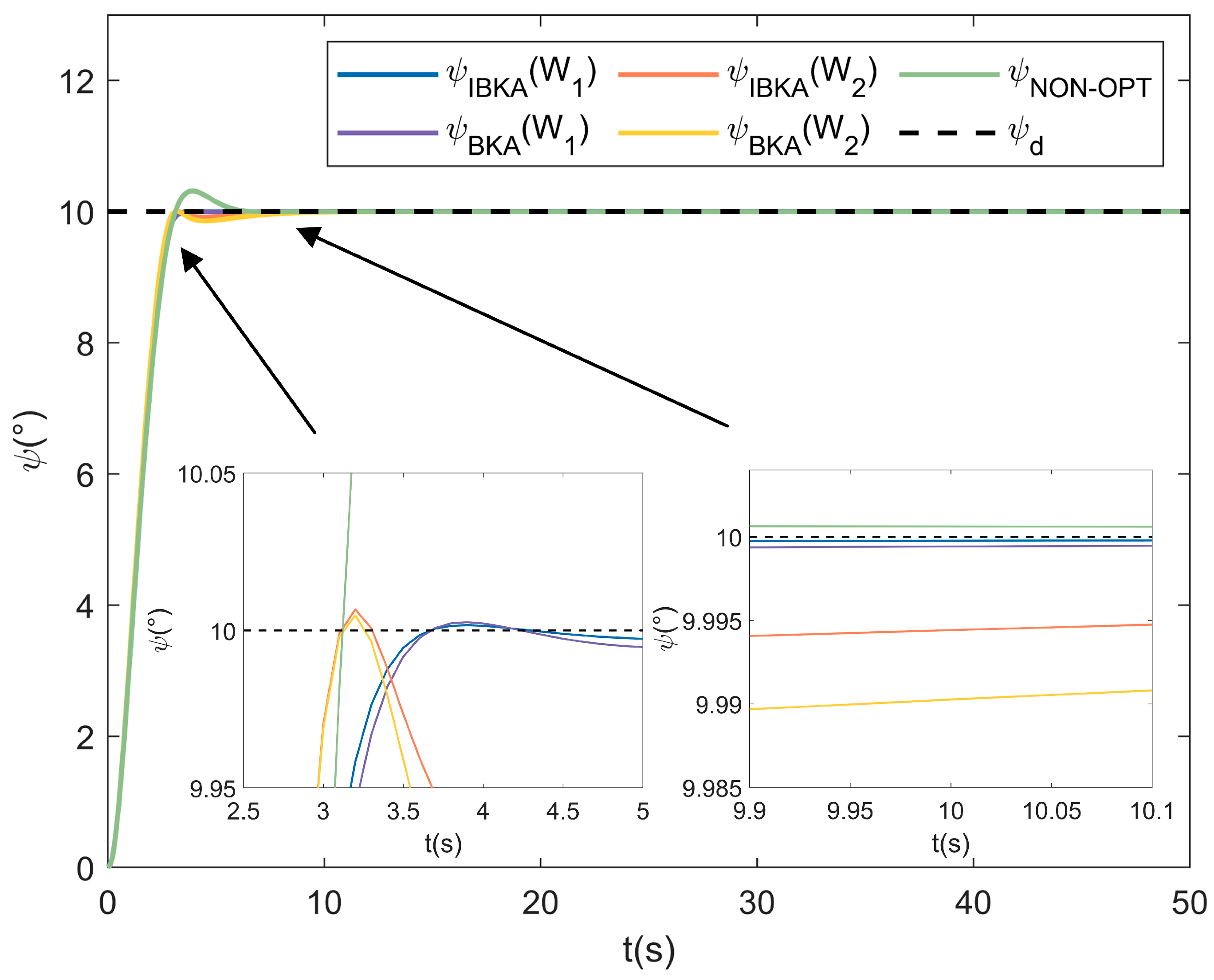
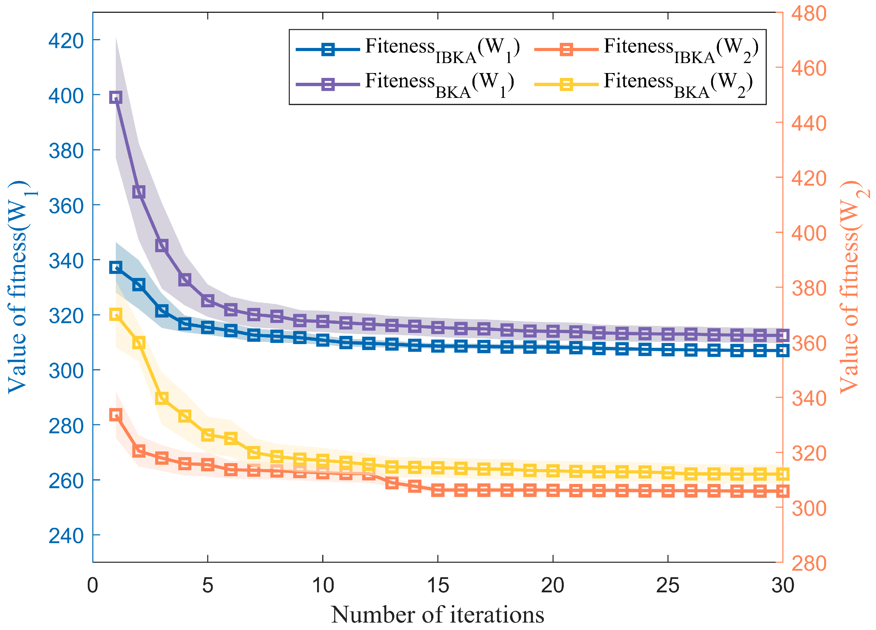
In the heading control experiment of the AUV, the initial value of the heading angle is set to ψ 0 = 0 , and the desired heading angle is ψ d = 10 . For the fitness function, the coefficients are set as W 1 = [ 10 10 0.1 10 ] and W 2 = [ 1 10 0.1 1 0 ] , respectively. The IBKA and BKA are used to optimize the parameters of the MPC controller, and the following results are obtained. Figure 3 shows the variation process of the heading angle in the AUV heading control experiment for the IBKA-MPC controller, BKA-MPC controller, and traditional MPC controller. It can be observed that when the coefficients of the fitness function are W 1 = [ 10 10 0.1 10 ] and W 2 = [ 1 10 0.1 1 0 ] , the simulation results of the IBKA-MPC controller are superior to those of the BKA-MPC controller and the MPC controller with non-optimized parameters in terms of overshoot and steady-state error. Here, the fitness optimization processes of the 20 repeated experiments for IBKA-MPC and BKA-MPC are processed. The 95% confidence interval for the experimental data of each iteration round is calculated to reflect the statistical fluctuation range of the data, resulting in the variation of fitness values with the number of iterations, as shown in Figure 4. In Figure 4, the left coordinate axis corresponds to the scenario when the coefficient is W 1 = [ 10 10 0.1 10 ] , representing the variation of IBKA fitness values and BKA fitness values with the number of iterations. The right coordinate axis corresponds to the variation of the IBKA fitness value and BKA fitness value with the number of iterations when the coefficient is W 2 = [ 1 10 0.1 1 0 ] . The filling of different colors represents the confidence interval of the corresponding optimization algorithm, and the polyline represents the average value of the fitness value for the corresponding iteration round. It can be observed from Figure 4 that under the conditions of different coefficients for the fitness function, the relationship F i t n e s s IBKA < F i t n e s s BKA always holds. This indicates that the optimization performance of IBKA for MPC parameters is superior to that of BKA in all cases, verifying the effective improvement of the LOBL strategy on the BKA.
After the data processing of the experimental results, Table 3 and Table 4, respectively, present the optimal individuals and corresponding fitness values when the coefficients of the fitness function are W 1 = [ 10 10 0.1 10 ] and W 2 = [ 1 10 0.1 1 0 ] . From this, the optimized weight matrices Q , R of the MPC controller and the prediction horizon N p can be obtained. It can be observed from the tables that, in the parameter optimization scenarios of the MPC controller corresponding to different fitness function coefficients, f i t n e s s IBKA < f i t n e s s BKA is satisfied in all cases. Table 5 and Table 6 then display the performance indicators of different controllers. The coefficient W 1 = [ 10 10 0.1 10 ] assigns a greater weight to the overshoot O V , which also means that the impact of O V on the fitness function f i t n e s s is more significant. Therefore, it can be observed from Table 5 that the overshoot O V of both the IBKA-MPC controller and the BKA-MPC controller is far smaller than that of the MPC controller with non-optimized parameters. Among them, when the coefficient of the fitness function is W 1 , the integral of absolute error I A E IBKA of the MPC controller optimized by IBKA decreases by 5.97 % compared with I A E NON - OPT of the MPC controller with non-optimized parameters, the integral of time-weighted absolute error I T A E IBKA decreases by 18.24 % compared with I T A E NON - OPT . When the coefficient of the fitness function is W 2 , I A E IBKA decreases by 6.29 % compared with I A E NON - OPT and I T A E IBKA decreases by 16.50 % compared with I T A E NON - OPT . Meanwhile, by comparing the optimization results of the IBKA-MPC controller and the BKA-MPC controller, it is found that the IAE, ITAE, and IAVU obtained by IBKA optimization are all smaller than those of the BKA-MPC controller. The above results indicate that the IBKA proposed in this paper is superior to BKA in terms of optimization performance.

4.2. Depth Tracking Experiment

This section presents the experimental verification of the depth tracking performance of the IBKA-MPC controller, based on the mathematical model of the AUV’s vertical plane motion provided in Section 2.1. Specifically, the surge velocity of the AUV is set to u = 5   m / s and the sampling time is determined as T s = 0 . 1   s . The continuous-time mathematical model is then discretized to obtain the discrete-time system. Here, based on the fitness function in Equation (24), the coefficients of the fitness function are set to W 3 = [ 0 100 1 10 ] . Comparative experiments involving IBKA-MPC, BKA-MPC, and the MPC controller with non-optimized parameters are conducted to verify the superiority of IBKA-MPC. All other parameter settings are kept consistent with those in the heading control experiment described in Section 4.1. Similarly, the programs for IBKA-MPC and BKA-MPC are run repeatedly 20 times, and the parameter scheme with the optimal fitness is ultimately selected.
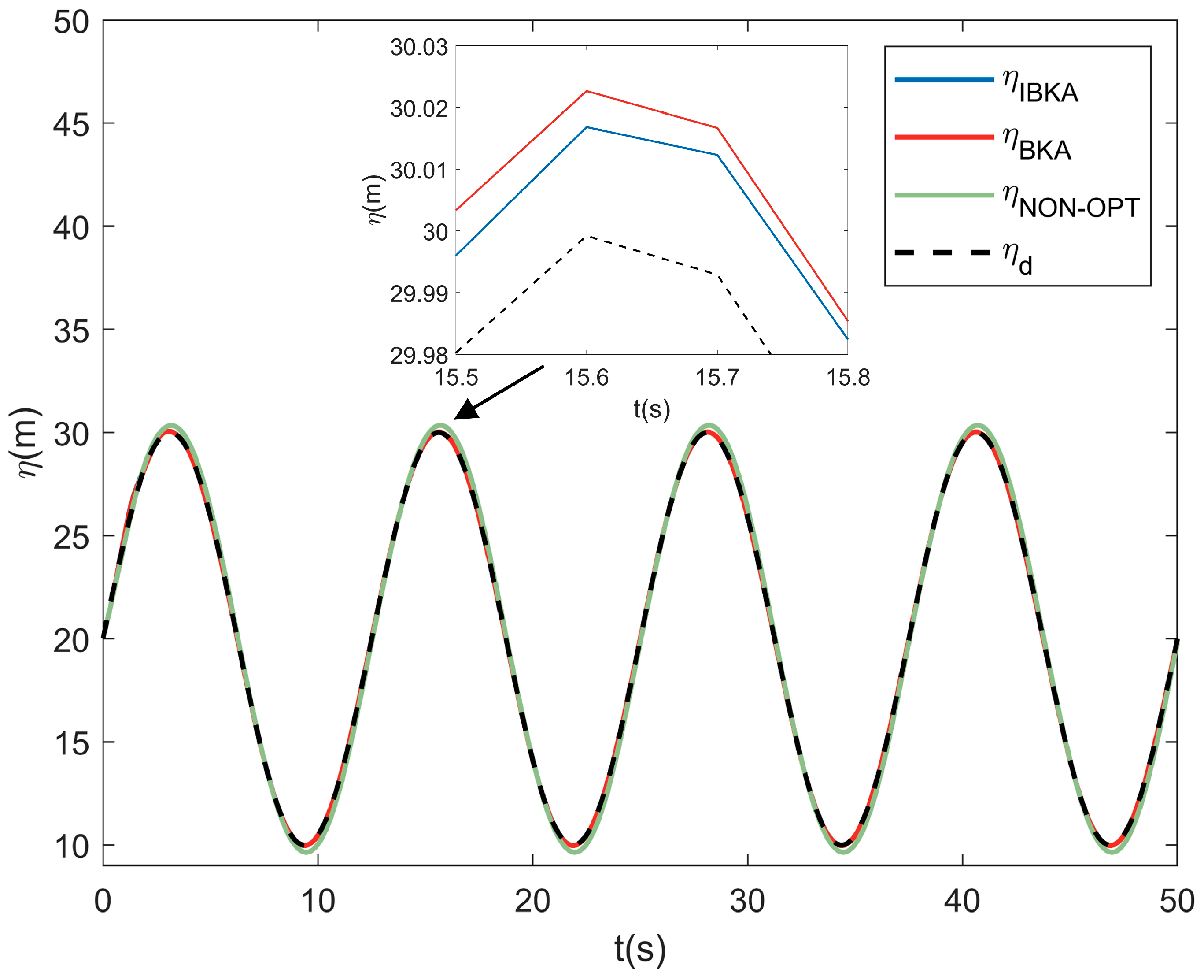
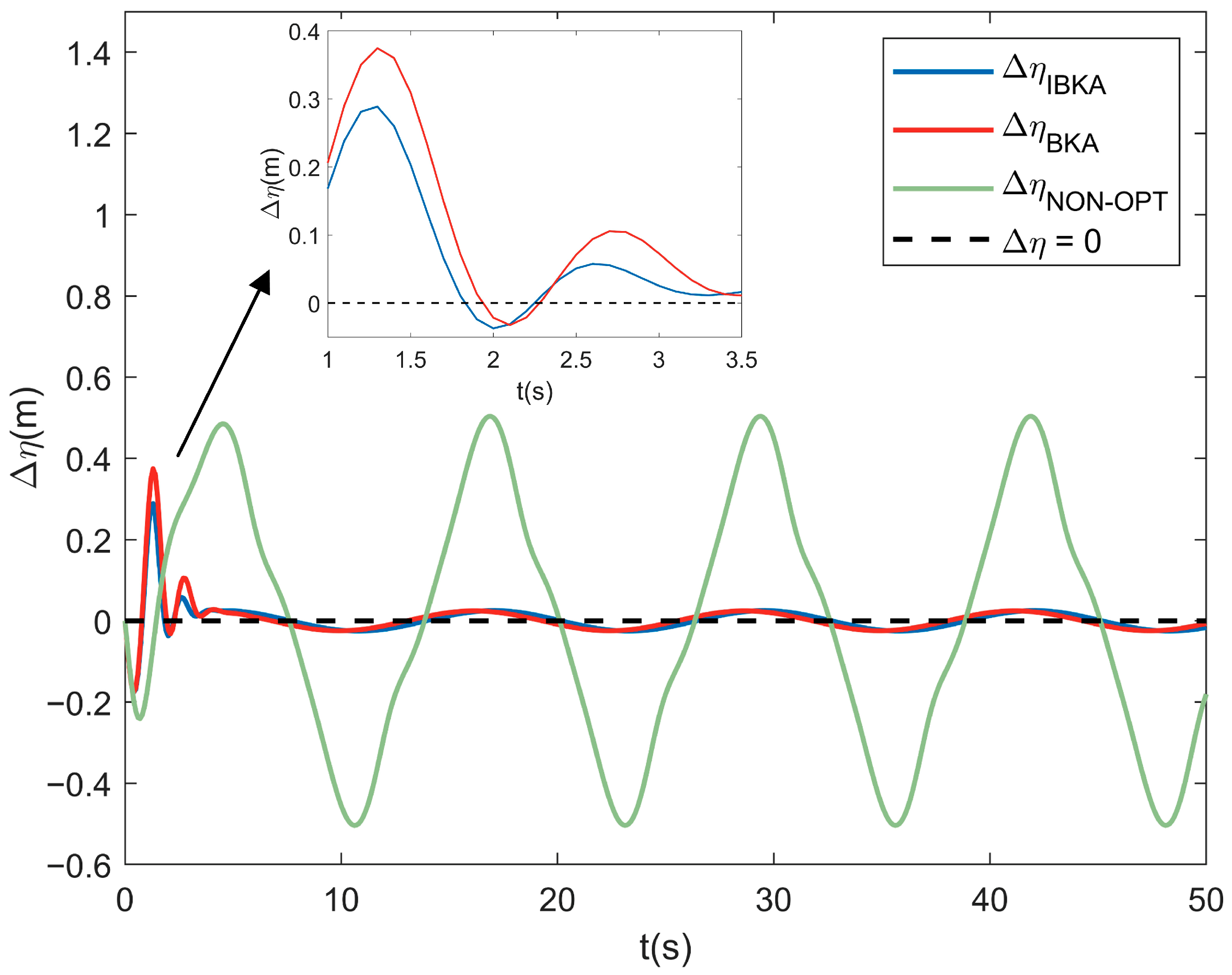
In the depth tracking experiment of the AUV, the initial depth value is set to η 0 = 20   m , and the trajectory for depth tracking is defined as η d = 20 + 10 sin 0.16 π t   m . Figure 5 illustrates the depth variation curves of the IBKA-MPC controller, BKA-MPC controller, and the MPC controller with non-optimized parameters during the AUV trajectory tracking process. As shown in Figure 6, the depth tracking error Δ η of the IBKA-MPC controller is smaller than that of both the BKA-MPC controller and MPC controller with non-optimized parameters. Thus, the depth tracking performance of the IBKA-MPC controller is superior to that of the BKA-MPC controller.
After processing the experimental results, Table 7 presents the optimal individual and the corresponding fitness value when the coefficient of the fitness function is W 3 = [ 0 100 1 10 ] . From this, the optimized weight matrices Q and R of the MPC controller and the prediction horizon N p can be determined. By analyzing the data in the table, it can be observed that when the coefficient of the fitness function is W 3 , the condition f i t n e s s IBKA < f i t n e s s BKA is satisfied, indicating that the fitness of IBKA improves after parameter optimization. Table 8 shows the performance indicators of different controllers. It is found that the I A E , I T A E , and I A V U of the IBKA-MPC controller during depth tracking are all smaller than those of MPC controller with non-optimized parameters. When the coefficient of the fitness function is W 3 , the integral of absolute error I A E IBKA decreases by 91.86 % compared to I A E NON - OPT , and the integral of time-weighted absolute error I T A E IBKA decreases by 94.78 % compared to I T A E NON - OPT . Meanwhile, under the condition that the I A V U of the IBKA-MPC controller and the BKA-MPC controller are similar, the conditions I A E IBKA < I A E BKA and I T A E IBKA < I T A E BKA hold. Thus, it is concluded that the performance of the IBKA-MPC controller is superior to that of the BKA-MPC controller.

4.3. Comparative Experiments with Classical Optimization Algorithms

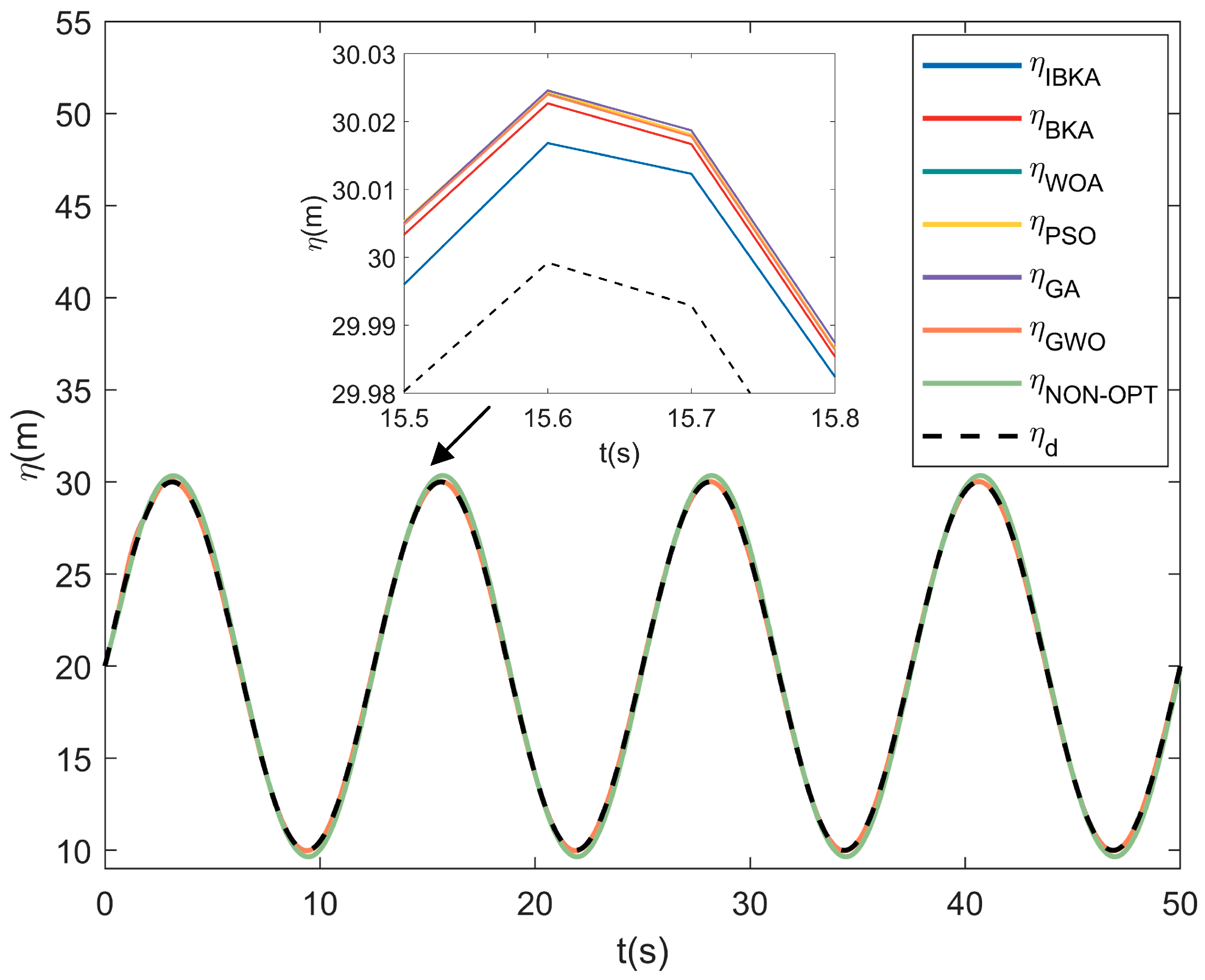
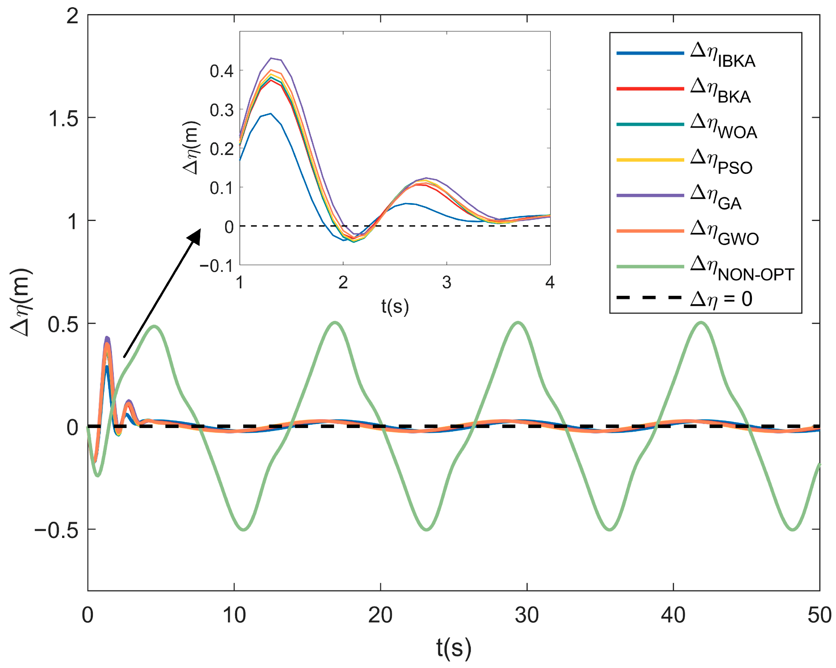
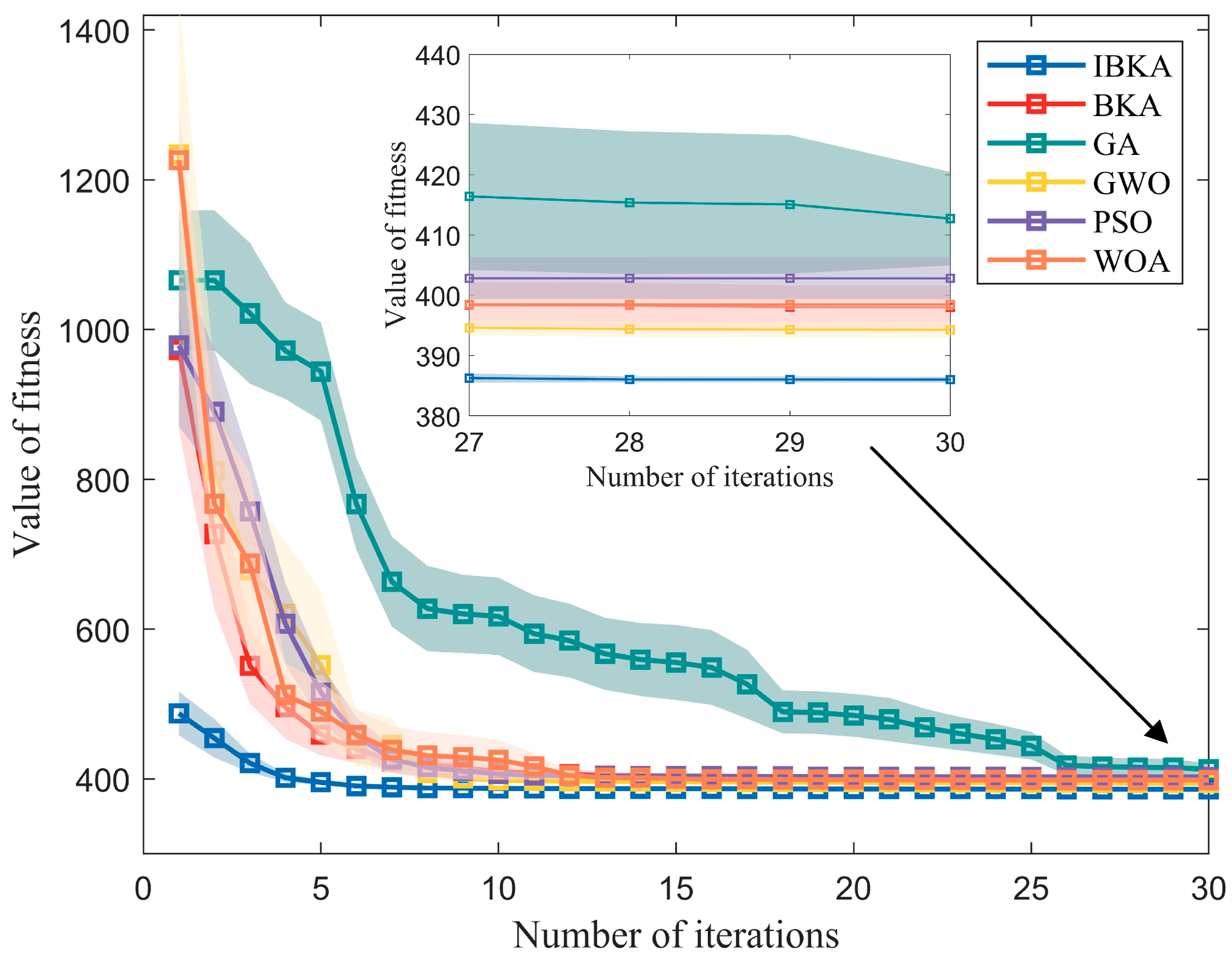
To investigate the convergence characteristics of the algorithm, this study selects the IBKA and conducts comparative experiments using four classical optimization algorithms: the Whale Optimization Algorithm (WOA), PSO, GA, and GWO. Each algorithm is independently executed 20 times under the same simulation conditions. Based on the coefficient settings in Section 4.2, experiments on the depth tracking of the AUV are performed. Figure 7 shows the depth variation curves of the optimal parameters of the MPC controller corresponding to different optimization algorithms in the AUV depth tracking experiment. Combined with Figure 8, it can be observed that the depth tracking error Δ η IBKA of IBKA-MPC is smaller than the tracking errors of other classical optimization algorithms, verifying the excellent optimization performance of the IBKA. Here, the results of 20 repeated experiments for different algorithms are processed to calculate the 95% confidence interval of the experimental data for each iteration, reflecting the statistical fluctuation range of the data. Thus, the variation of the fitness value with the number of iterations, as shown in Figure 9, is obtained. The different color fillings represent the confidence interval for each corresponding optimization algorithm, and the polyline represents the average fitness value for the corresponding iteration round. It can be observed that after 30 iterations, the optimal parameters obtained by IBKA result in the minimum fitness value for the IBKA-MPC simulation, indicating that its optimization capability is superior to that of classical optimization algorithms.
After processing the experimental results of different classical optimization algorithms, Table 9 presents the optimal individuals and the corresponding fitness values for each algorithm. From these, the optimized weight matrices Q and R of the MPC controller and the prediction horizon N p can be determined. By analyzing the data in the table, it can be observed that in the depth tracking experiment of the MPC controller with optimal parameters, f i t n e s s IBKA is smaller than the fitness values of other classical algorithms. Table 10 shows the performance indicators of the controllers optimized by different algorithms. When I A V U is close, the I A E and I T A E of the IBKA-MPC controller during depth tracking are significantly smaller than those of the MPC controllers optimized by classical algorithms. The above experimental results indicate that the IBKA, which incorporates the LOBL strategy, yields optimal parameter control effects that are superior to those obtained by the WOA, PSO, GA, and GWO algorithms. This further demonstrates that IBKA possesses excellent optimization performance.

5. Conclusions

This study introduces the IBKA into the field of MPC controller parameter optimization for the first time. It innovatively integrates the LOBL strategy into the BKA, resulting in the IBKA. Meanwhile, a fitness function with adjustable coefficients is designed, which is applied to the field of AUV motion control for various control objectives and scenarios. Through 20 repeated experiments, it is verified that the controller parameters with the minimum fitness can be obtained via IBKA optimization. Furthermore, when the MPC controller adopts the optimal parameters optimized by IBKA, its control performance indicators in course control and depth tracking scenarios are significantly improved compared to the simulation results of the non-optimized MPC. It effectively addresses the problem that the traditional selection of the MPC weight matrices Q , R and the prediction horizon N p relies on experience. Meanwhile, through comparative experiments with four classical optimization algorithms—namely, WOA, PSO, GA, and GWO—it is verified that the IBKA, incorporating the LOBL strategy, exhibits superior convergence performance.
For future work, it is suggested that the performance of the proposed IBKA-MPC controller be tested in practical complex navigation scenarios.

Author Contributions

Conceptualization, J.W. and H.W.; methodology, J.W.; software, J.W.; validation, J.W., H.W. and Y.Z.; formal analysis, J.W., H.W. and S.R.; investigation, J.W. and H.W.; resources, J.W.; data curation, J.W. and Y.Z.; writing—original draft preparation, J.W.; writing—review and editing, J.W., Y.Z. and H.W.; visualization, J.W.; supervision, Y.Z. and S.R.; project administration, H.W.; funding acquisition, H.W. All authors have read and agreed to the published version of the manuscript.

Funding

This study was funded by the Laboratory of Science and Technology on Marine Navigation and Control, China State Shipbuilding Corporation, grant number 2023010302.

Data Availability Statement

The raw data supporting the conclusions of this article will be made available by the authors on request.

Conflicts of Interest

The authors declare no conflicts of interest.

Abbreviations

The following abbreviations are used in this manuscript:
MPCModel Predictive Control
AUVsAutonomous Underwater Vehicles
IBKAImproved Black-winged Kite Algorithm
LOBLLens Opposition-Based Learning
IAEIntegral of Absolute Error
ITAEIntegral of Time-weighted Absolute Error
PIDProportional–Integral–Derivative
SMCSliding Mode Control
LQRLinear Quadratic Regulator
GAGenetic Algorithm
PSOParticle Swarm Optimization
GWOGrey Wolf Optimization
ACOAnt Colony Optimization
BOAButterfly Optimization Algorithm
6-DOFSix Degree-of-freedom
IAVUIntegral of the Absolute Value for the Variation of the Control Signal
OVOvershoot
WOAWhale Optimization Algorithm

References

  1. Khodayari, M.H.; Balochian, S. Modeling and control of autonomous underwater vehicle (AUV) in heading and depth attitude via self-adaptive fuzzy PID controller. J. Mar. Sci. Technol. 2015, 20, 559–578. [Google Scholar] [CrossRef]
  2. Bingul, Z.; Gul, K. Intelligent-PID with PD Feedforward Trajectory Tracking Control of an Autonomous Underwater Vehicle. Machines 2023, 11, 300. [Google Scholar] [CrossRef]
  3. Guerrero, J.; Torres, J.; Creuze, V.; Chemori, A. Adaptive disturbance observer for trajectory tracking control of underwater vehicles. Ocean Eng. 2020, 200, 107080. [Google Scholar] [CrossRef]
  4. Qiao, L.; Ruan, S.T.; Zhang, G.Q.; Zhang, W.D. Robust H2 optimal depth control of an autonomous underwater vehicle with output disturbances and time delay. Ocean Eng. 2018, 165, 399–409. [Google Scholar] [CrossRef]
  5. Cui, R.X.; Zhang, X.; Cui, D. Adaptive sliding-mode attitude control for autonomous underwater vehicles with input nonlinearities. Ocean Eng. 2016, 123, 45–54. [Google Scholar] [CrossRef]
  6. Chen, B.; Hu, J.P.; Zhao, Y.Y.; Ghosh, B.K. Finite-time observer based tracking control of uncertain heterogeneous underwater vehicles using adaptive sliding mode approach. Neurocomputing 2022, 481, 322–332. [Google Scholar] [CrossRef]
  7. Duan, Y.; Xiang, X.B.; Liu, C.; Yang, L.C. Double-loop LQR depth tracking control of underactuated AUV: Methodology and comparative experiments. Ocean Eng. 2024, 300, 117410. [Google Scholar] [CrossRef]
  8. Li, B.; Su, T.C. Nonlinear heading control of an autonomous underwater vehicle with internal actuators. Ocean Eng. 2016, 125, 103–112. [Google Scholar] [CrossRef]
  9. Priyadarsini, L.; Kundu, S.; Maharana, M.K.; Ganthia, B.P. Controller Design for the Pitch Control of an Autonomous Underwater Vehicle. Eng. Technol. Appl. Sci. Res. 2022, 12, 8967–8971. [Google Scholar] [CrossRef]
  10. Zhang, Y.D.; Liu, X.F.; Luo, M.Z.; Yang, C.G. MPC-based 3-D trajectory tracking for an autonomous underwater vehicle with constraints in complex ocean environments. Ocean Eng. 2019, 189, 106309. [Google Scholar] [CrossRef]
  11. Arcos-Legarda, J.; Gutiérrez, A. Robust Model Predictive Control Based on Active Disturbance Rejection Control for a Robotic Autonomous Underwater Vehicle. J. Mar. Sci. Eng. 2023, 11, 929. [Google Scholar] [CrossRef]
  12. Schwenzer, M.; Ay, M.; Bergs, T.; Abel, D. Review on model predictive control: An engineering perspective. Int. J. Adv. Manuf. Technol. 2021, 117, 1327–1349. [Google Scholar] [CrossRef]
  13. Wieber, P.B. Trajectory free linear model predictive control for stable walking in the presence of strong perturbations. In Proceedings of the 6th IEEE/RAS International Conference on Humanoid Robots, Genoa, Italy, 4–6 December 2006; pp. 137–142. [Google Scholar]
  14. Schubert, P.; Stemmler, S.; Abel, D. Towards Predictive Anti-Sway Control of Hanging Loads: Model-based Controller Design for a Knuckle Boom Crane. In Proceedings of the 18th European Control Conference (ECC), Naples, Italy, 25–28 June 2019; pp. 2276–2282. [Google Scholar]
  15. Li, S.B.; Li, K.Q.; Rajamani, R.; Wang, J.Q. Model Predictive Multi-Objective Vehicular Adaptive Cruise Control. IEEE Trans. Control Syst. Technol. 2011, 19, 556–566. [Google Scholar] [CrossRef]
  16. Yoon, S.; Jeon, H.; Kum, D. Predictive Cruise Control Using Radial Basis Function Network-Based Vehicle Motion Prediction and Chance Constrained Model Predictive Control. IEEE Trans. Intell. Transp. Syst. 2019, 20, 3832–3843. [Google Scholar] [CrossRef]
  17. Jimoh, I.A.; Zaman, T.; Syed, M.; Yue, H.; Burt, G.; El Moursi, M.S. Tube-Based Linear Parameter-Varying Model Predictive Control for Wind Energy Conversion Systems. IEEE Trans. Sustain. Energy 2025, 16, 1225–1237. [Google Scholar] [CrossRef]
  18. Shen, C.; Shi, Y.; Buckham, B. Trajectory Tracking Control of an Autonomous Underwater Vehicle Using Lyapunov-Based Model Predictive Control. IEEE Trans. Ind. Electron. 2018, 65, 5805. [Google Scholar] [CrossRef]
  19. Jimoh, I.A.; Yue, H.; Küçükdemiral, I.B. Autonomous Underwater Vehicle Positioning Control—A Velocity Form LPV-MPC Approach. In Proceedings of the 22nd World Congress of the International Federation of Automatic Control (IFAC), Yokohama, Japan, 9–14 June 2023; pp. 4388–4393. [Google Scholar]
  20. Hong, H.C.; Yang, Z.Q.; Li, J.W.; Xu, G.H.; Xia, Y.K.; Xu, K. State-Transform MPC-SMC-Based Trajectory Tracking Control of Cross-Rudder AUV Carrying Out Underwater Searching Tasks. J. Mar. Sci. Eng. 2024, 12, 883. [Google Scholar] [CrossRef]
  21. Hao, L.Y.; Wang, R.Z.; Shen, C.; Shi, Y. Trajectory Tracking Control of Autonomous Underwater Vehicles Using Improved Tube-Based Model Predictive Control Approach. Ieee Trans. Ind. Inform. 2024, 20, 5647–5657. [Google Scholar] [CrossRef]
  22. Wang, L.L.; Xu, X.Y.; Han, B.; Zhang, H.P. Multiple Autonomous Underwater Vehicle Formation Obstacle Avoidance Control Using Event-Triggered Model Predictive Control. J. Mar. Sci. Eng. 2023, 11, 2016. [Google Scholar] [CrossRef]
  23. Yao, X.L.; Wang, X.W.; Wang, F.; Zhang, L. Path Following Based on Waypoints and Real-Time Obstacle Avoidance Control of an Autonomous Underwater Vehicle. Sensors 2020, 20, 795. [Google Scholar] [CrossRef]
  24. Jimoh, I.A.; Yue, H. A Velocity Form Model Predictive Control of an Autonomous Underwater Vehicle. IEEE J. Ocean. Eng. 2025, 50, 1127–1139. [Google Scholar] [CrossRef]
  25. Xiong, Y.; Pan, L.; Xiao, M.; Xiao, H. Motion control and path optimization of intelligent AUV using fuzzy adaptive PID and improved genetic algorithm. Math. Biosci. Eng. 2022, 20, 9208–9245. [Google Scholar] [CrossRef]
  26. Eltayeb, A.; Ahmed, G.; Imran, I.H.; Alyazidi, N.M.; Abubaker, A. Comparative Analysis: Fractional PID vs. PID Controll. Robot. Arm Using Genet. Algorithm Optimization. Automation 2024, 5, 230–245. [Google Scholar] [CrossRef]
  27. Fan, X.; Wang, J.Y.; Wang, H.F.; Yang, L.; Xia, C.G. LQR Trajectory Tracking Control of Unmanned Wheeled Tractor Based on Improved Quantum Genetic Algorithm. Machines 2023, 11, 62. [Google Scholar] [CrossRef]
  28. Ma, B.; Li, P.H. Optimal flexible power allocation energy management strategy for hybrid energy storage system with genetic algorithm based model predictive control. Energy 2025, 324, 135958. [Google Scholar] [CrossRef]
  29. Liu, W.X.; Xia, Z.H.; Wu, L.Y.; Guo, G.K.; Zhu, C.; Zhang, Z.Y.; Cui, L. Underwater remotely operated vehicle control system with optimized PID based on improved particle swarm optimization. Desalination Water Treat. 2023, 314, 322–329. [Google Scholar] [CrossRef]
  30. Zhang, Y.L.; Li, Y.F.; Liu, Y.; Yi, G.R. Control of Cricket System Using LQR Controller Optimized by Particle Swarm Optimization. In Proceedings of the 3rd International Conference on Applied Mathematics, Modeling and Simulation (AMMS), Shanghai, China, 20–21 September 2020. [Google Scholar]
  31. Zhu, D.X.; Cui, N. Design of intelligent control for flexible linear double inverted pendulum based on particle swarm optimization algorithm. Syst. Sci. Control Eng. 2024, 12, 2332409. [Google Scholar] [CrossRef]
  32. Li, S.H.; Yang, Z.K.; Li, B.L. Four-wheel steering vehicle trajectory tracking control based on PSO optimized MPC. Phys. Scr. 2024, 99, 095252. [Google Scholar] [CrossRef]
  33. He, Q.; Li, H.; Zhang, R.J.; Jia, T.C. Study on the LQR Control of High-speed Elevator Car Horizontal Vibration Based on the Jumping Inertia Weight Particle Swarm Optimization. Int. J. Acoust. Vib. 2022, 27, 122–137. [Google Scholar] [CrossRef]
  34. Sun, M.X.; Ji, C.Y.; Luan, T.T.; Wang, N. LQR Pendulation Reduction Control of Ship-Mounted Crane Based on Improved Grey Wolf Optimization Algorithm. Int. J. Precis. Eng. Manuf. 2023, 24, 395–407. [Google Scholar] [CrossRef]
  35. Xiong, X.; Chen, C.Z.; Liu, Y.M.; Li, Z.H.; Xu, F. Research on performance magnetorheological semi-active suspension based on improved gray wolf algorithm-optimized linear quadratic regulator control. Int. J. Dyn. Control 2024, 12, 4157–4170. [Google Scholar] [CrossRef]
  36. Manna, S.; Mani, G.; Ghildiyal, S.; Stonier, A.A.; Peter, G.; Ganji, V.; Murugesan, S. Ant Colony Optimization Tuned Closed-Loop Optimal Control Intended for Vehicle Active Suspension System. IEEE Access 2022, 10, 53735–53745. [Google Scholar] [CrossRef]
  37. Zhang, G.Y.; Wang, H.B.; Zhao, W.; Guan, Z.Y.; Li, P.F. Application of Improved Multi-Objective Ant Colony Optimization Algorithm in Ship Weather Routing. J. Ocean Univ. China 2021, 20, 45–55. [Google Scholar] [CrossRef]
  38. Arrieta, O.; Campos, D.; Rico-Azagra, J.; Gil-Martínez, M.; Rojas, J.D.; Vilanova, R. Model-Based Optimization Approach for PID Control of Pitch-Roll UAV Orientation. Mathematics 2023, 11, 3390. [Google Scholar] [CrossRef]
  39. Yuvapriya, T.; Lakshmi, P.; Elumalai, V.K. Experimental Validation of LQR Weight Optimization Using Bat Algorithm Applied to Vibration Control of Vehicle Suspension System. IETE J. Res. 2023, 69, 8142–8152. [Google Scholar] [CrossRef]
  40. Zhang, C.J.; Bai, C.Y.; Ding, Y.Y.; Zhang, Q. LQR Optimal Control of Triple Inverted Pendulum Based on Fuzzy quotient space theory. In Proceedings of the IEEE International Conference on Granular Computing (GrC), Hangzhou, China, 11–13 August 2012; pp. 633–638. [Google Scholar]
  41. Ata, B.; Gencal, M.C. Comparison of optimization approaches on linear quadratic regulator design for trajectory tracking of a quadrotor. Evol. Intell. 2024, 17, 3225–3240. [Google Scholar] [CrossRef]
  42. Li, H.; Lu, Y.; Li, Y.; Zheng, S.; Sun, C.; Zhang, J.; Liu, L. Optimization of Model Predictive Control for Autonomous Vehicles Through Learning-Based Weight Adjustment. IEEE Trans. Intell. Transp. Syst. 2024, 1–12. [Google Scholar] [CrossRef]
  43. Qiu, Z.; Zhang, L.; Zhang, H.; Liang, H.B.; Li, Y.X. A plunger lifting optimization control method based on APSO-MPC for edge computing applications. Sci. Rep. 2025, 15, 4356. [Google Scholar] [CrossRef]
  44. Sun, X.B.; Li, J.J.; Zhang, W.; Sun, G.Y.; Zhang, X.Y.; Xu, H.Z. Two-Step Optimization Method of Freight Train Speed Curve Based on Rolling Optimization Algorithm and MPC. Vehicles 2025, 7, 17. [Google Scholar] [CrossRef]
  45. Fossen, T.I. Guidance and Control of Ocean Vehicles; JOHN WILEY & SONS: Chichester, UK, 1994. [Google Scholar]
  46. Prestero, T. Verification of a Six-Degree of Freedom Simulationmodel for the REMUS Autonomous Underwater Vehicle. S.M. Thesis, MIT, Cambridge, MA, USA, 2001. [Google Scholar]
  47. Warner, D.C. Design, Simulation, and Experimental Verification of a Computer Model and Enhanced Position Estimator for the NPS AUV II. Ph.D. Thesis, Naval Postgraduate School, California, MA, USA, 2018. [Google Scholar]
  48. Wang, J.; Wang, W.C.; Hu, X.X.; Qiu, L.; Zang, H.F. Black-winged kite algorithm: A nature-inspired meta-heuristic for solving benchmark functions and engineering problems. Artif. Intell. Rev. 2024, 57, 98. [Google Scholar] [CrossRef]
  49. Wang, S.X.; Xu, B.R.; Zheng, Y.J.; Yue, Y.G.; Xiong, M.J. Path Optimization Strategy for Unmanned Aerial Vehicles Based on Improved Black Winged Kite Optimization Algorithm. Biomimetics 2025, 10, 310. [Google Scholar] [CrossRef] [PubMed]
  50. Dai, F.; Ma, T.L.; Gao, S. Optimal Design of a Fractional Order PIDD2 Controller for an AVR System Using Hybrid Black-Winged Kite Algorithm. Electronics 2025, 14, 2315. [Google Scholar] [CrossRef]
  51. Xiao, Y.N.; Cui, H.; Hussien, A.G.; Hashim, F.A. MSAO: A multi-strategy boosted snow ablation optimizer for global optimization and real-world engineering applications. Adv. Eng. Inform. 2024, 61, 102464. [Google Scholar] [CrossRef]
Figure 1. Motion coordinate systems of the AUV.
Jmse 13 02018 g001
Figure 2. Basic principle of MPC.
Jmse 13 02018 g002
Figure 3. Results of MPC heading control with parameter optimization.
Jmse 13 02018 g003
Figure 4. Comparison of convergence curves of different algorithms in the heading control experiment.
Jmse 13 02018 g004
Figure 5. Results of MPC depth tracking with parameter optimization.
Jmse 13 02018 g005
Figure 6. Results of MPC depth tracking errors with parameter optimization.
Jmse 13 02018 g006
Figure 7. Depth tracking results of MPC after parameter optimization between IBKA and classical optimization algorithms.
Jmse 13 02018 g007
Figure 8. Depth tracking results errors of MPC after parameter optimization between IBKA and classical optimization algorithms.
Jmse 13 02018 g008
Figure 9. Comparison of convergence curves between IBKA and classical optimization algorithms.
Jmse 13 02018 g009
Table 1. Search ranges for parameter optimization in heading control experiment.
ParameterLower BoundUpper Bound
d i a g Q T 0.1 0.1 0.1 30 30 200
d i a g R T 0.1 1
N p 5 30
Table 2. Search ranges for parameter optimization in depth tracking experiment.
ParameterLower BoundUpper Bound
d i a g Q T 0.01 0.01 0.01 0.01 30 30 30 200
d i a g R T 0.01 1
N p 2 30
Table 3. Parameter optimization results for different controllers in heading control with the coefficient set to W 1 .
Controllers Q R N p F i t n e s s
IBKA-MPC d i a g 0.11 5.09 20.0 d i a g 0.41 5 306.400
BKA-MPC d i a g 0.10 2.33 12.01 d i a g 0.32 16 309.649
MPC d i a g 0.10 0.10 100.00 d i a g 0.5 10 352.699
Table 4. Parameter optimization results for different controllers in heading control with the coefficient set to W 2 .
Controllers Q R N p F i t n e s s
IBKA-MPC d i a g 0.20 5.18 14.66 d i a g 0.10 10 308.152
BKA-MPC d i a g 0.15 1.85 6.83 d i a g 0.10 5 313.993
MPC d i a g 0.10 0.10 100.00 d i a g 0.5 10 324.494
Table 5. Performance indicators of different controllers in heading control with the coefficient set to W 1 .
Controllers O V % I A E I T A E I A V U
IBKA-MPC 1.7 × 10 3 14.717 140.870 14.497
BKA-MPC 3.2 × 10 3 14.887 153.425 15.524
MPC 3.13 15.652 172.288 14.761
Table 6. Performance indicators of different controllers in heading control with the coefficient set to W 2 .
Controllers O V % I A E I T A E I A V U
IBKA-MPC 6.7 × 10 2 14.668 143.862 14.704
BKA-MPC 4.8 × 10 2 15.047 164.673 14.701
MPC 3.13 15.652 172.288 14.761
Table 7. Parameter optimization results of different controllers in depth tracking with the coefficient set to W 3 .
Controllers Q R N p F i t n e s s
IBKA-MPC d i a g 1.90 0.01 0.40 48.35 d i a g 0.02 2 383.85
BKA-MPC d i a g 0.01 0.01 0.01 3.78 d i a g 0.01 2 392.29
MPC d i a g 1.00 1.00 1.00 10.00 d i a g 0.10 10 1946.89
Table 8. Performance indicators of different controllers in depth tracking with the coefficient set to W 3 .
Controllers I A E I T A E I A V U
IBKA-MPC 1.098 18.049 25.772
BKA-MPC 1.142 20.316 25.774
MPC 13.492 345.682 25.907
Table 9. Parameter optimization results of MPC controllers under different optimization algorithms.
Controllers Q R N p F i t n e s s
IBKA-MPC d i a g 1.90 0.01 0.40 48.35 d i a g 0.02 2 383.85
BKA-MPC d i a g 0.01 0.01 0.01 3.78 d i a g 0.01 2 392.29
WOA-MPC d i a g 0.01 0.01 0.01 9.512 d i a g 0.03 2 395 . 66
PSO-MPC d i a g 1.37 0.10 0.01 200 d i a g 0.69 27 397 . 11
GA-MPC d i a g 5.35 0.10 0.10 190.65 d i a g 0.39 22 399 . 93
GWO-MPC d i a g 2.71 0.21 0.10 200.00 d i a g 0.57 20 397 . 63
Table 10. Comparison of performance indicators of MPC controllers between IBKA and classical optimization algorithms.
Controllers I A E I T A E I A V U
IBKA-MPC 1.098 18.049 25.772
BKA-MPC 1.142 20.316 25.774
WOA-MPC 1.166 20 . 663 25 . 835
PSO-MPC 1 . 179 20 . 780 25 . 846
GA-MPC 1 . 202 20 . 238 25 . 882
GWO-MPC 1 . 185 20 . 737 25 . 841
Disclaimer/Publisher’s Note: The statements, opinions and data contained in all publications are solely those of the individual author(s) and contributor(s) and not of MDPI and/or the editor(s). MDPI and/or the editor(s) disclaim responsibility for any injury to people or property resulting from any ideas, methods, instructions or products referred to in the content.