Review

Dynamics of Offshore Wind Turbine Foundation: A Critical Review and Future Directions

1
Department of Engineering Mechanics, Hohai University, Nanjing 211100, China
2
Jiangsu Province Wind Power Structural Engineering Research Center, Nanjing 211100, China
3
Key Laboratory of Ministry of Education for Coastal Disaster and Protection, Hohai University, Nanjing 210098, China
4
Cooperate Innovation Center for Coastal Development and Protection, Nanjing 210098, China
5
Suzhou Institute, Hohai University, Suzhou 215000, China
6
Faculty of Infrastructure Engineering, Dalian University of Technology, Dalian 116024, China
*
Author to whom correspondence should be addressed.
These authors contributed equally to this work.
J. Mar. Sci. Eng. 2025, 13(10), 2016; https://doi.org/10.3390/jmse13102016
Submission received: 27 August 2025 / Revised: 13 October 2025 / Accepted: 20 October 2025 / Published: 21 October 2025
(This article belongs to the Section Coastal Engineering)

Abstract

Offshore wind turbines (OWTs) are being developed with larger capacities for deeper waters, facing complex environmental loads that challenge structural safety. In contrast to onshore turbines, OWT foundations must withstand combined hydrodynamic forces (waves and currents), leading to substantially higher construction costs. For floating offshore wind turbines (FOWTs), additional considerations include radiation hydrodynamic loads and additional hydrodynamic damping effects caused by platform motion. Dynamic analysis of these foundations remains a critical bottleneck, presenting new challenges for offshore wind power advancement. This article first introduces the main structural types of OWT foundations, with case studies predominantly from China. The remaining part of the article proceeds as follows: dynamics of fixed OWT foundations, dynamics of FOWT foundations, and conclusions. Next, it covers several important topics related to fixed offshore wind turbines, including pile–soil interaction, wave loads, and seismic analysis. It then discusses support platform motion analysis, hydroelastic analysis, and mooring system characteristics of floating offshore wind turbines. Finally, it presents some insights to improve design and optimization methods for enhancing the safety and reliability of offshore wind turbines. This research clarifies OWT foundation dynamics, helping researchers address challenges and optimize designs.

1. Introduction

Offshore wind power is becoming an important direction to study wind power utilization due to its characteristic stable wind velocity and high wind energy density. According to the prediction of GWEC, the global installation of new wind turbines will reach an all-time high from 2023 to 2027, with an estimated 680 GW, out of which 130 GW will be installed offshore. The global offshore wind power market is expected to grow from 8.8 GW in 2022 to 35.5 GW in 2027, and globally, the proportion of newly installed offshore wind turbines (OWTs) in total will rise from the current 11% to 23% by 2027.
The foundation of OWTs is critical for providing stability and safety to the entire unit. In a recent study by Shanghai Jiao Tong University [1], existing classic foundation types were reviewed, and geotechnical and structural research issues related to nearshore wind turbine systems were investigated to shed light on this critical area. The foundation structures and loading forms of OWTs are quite complicated and face nonlinearity, multi-scale, and elastic effects. The academic community has highlighted that in OWTs [2], which are highly dynamic systems, the flexibility and damping characteristics of the connections between their main substructures significantly influence their overall dynamic behavior. Similarly, the foundations of floating offshore wind turbines (FOWTs) face numerous challenges due to the motion of the platform, nonlinear dynamic features of mooring lines, and more. All of these factors present significant challenges to the development of OWTs.
This article is written in light of the pressing academic and practical demand for dynamic analysis of offshore wind power foundations, particularly given the growing complexity and diversity of wind turbine foundation structures. To this end, it first presents the structural characteristics of mainstream OWT foundations. The article subsequently delves into the current state and advancements in dynamic research on fixed offshore wind turbines, with a focus on pile–soil interaction, wave loads, and seismic analysis. Regarding floating offshore wind turbines, the article commences by outlining the advancements in dynamic research, encompassing the analysis of support platform motion, hydroelastic analysis, and the investigation of mooring system characteristics. The timeline of the relevant dynamic analysis studies on the OWT foundations mentioned above is presented in Figure 1. Through these exhaustive analyses, the aim of this article is to offer insightful guidance for the design and optimization of offshore wind power foundations, thereby enhancing their safety and reliability, and concurrently minimizing development costs.

2. Structural Foundation Types of OWTs

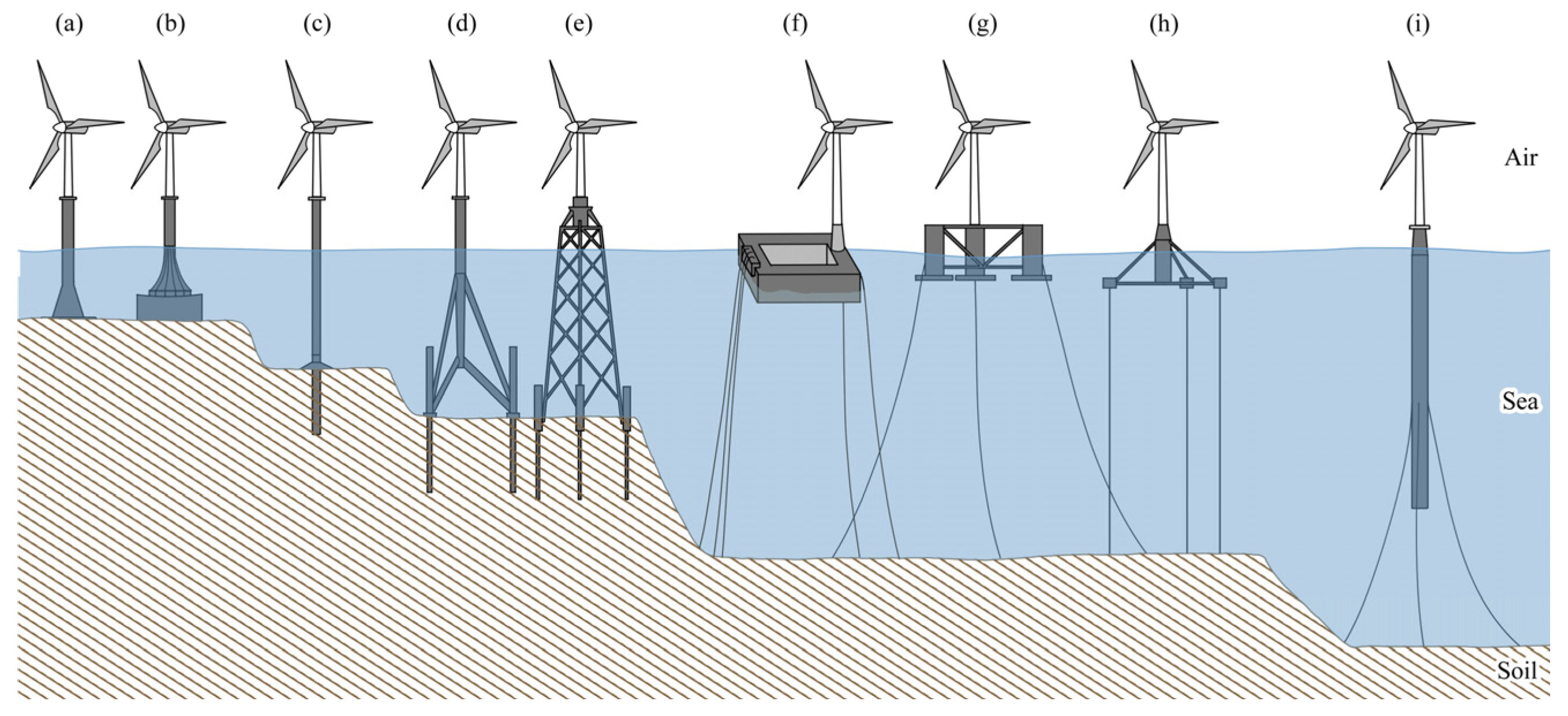
With the development and progress of offshore wind power at different depths and in different sea areas, multiple structural types of support systems of OWTs have been developed. Depending on whether there is direct contact with the seabed, existing structural types of offshore wind power foundations can be divided into fixed-type and floating-type. The traditional fixed foundations are applicable to inshore areas. When the water depth is higher than 60 m, the economic cost of these foundations is increased significantly, and it is difficult to guarantee safety [3]. Hence, the concept of the floating wind turbine was proposed, and it became the main force in the development and utilization of offshore wind energy. At present, the structural types for foundations of mainstream OWTs are shown in Figure 2 [4]. The structural cost of the foundation is about 20%~30% of the total engineering cost. Therefore, it is very important to reasonably choose the appropriate foundation structural type according to the hydrological environment, soil properties of the seabed, and requirements for use.
To illustrate the practical adaptation of these foundation types in real-world scenarios, Table 1 summarizes typical offshore wind power projects across different regions, detailing their foundation types, water depths, installed capacities, and key application features for comparative analysis.

2.1. Foundation of Fixed Wind Turbines

Gravity-based foundations and pile-supported foundations are two major structural foundation types of fixed offshore wind turbines. They have been applied to many offshore wind power fields. The pile-supported foundation is the type that is used mostly by OWTs at present. According to structural types, foundations of OWTs can be divided into different types, such as monopile foundation, tripod foundation, jacket foundation, and so on [8].
According to the literature [9], offshore wind power projects using gravity-based foundations experience an average cost overrun of 5.4%, while those using monopile foundations experience 7.4%. Tripods and jacket structures, on the other hand, have an average cost overrun as high as 24.7%, but this does not necessarily reflect their lower economic efficiency. Most offshore wind power fields are located in shallow water areas (0–30 m) and use gravity-based, monopile, or tripod foundations. However, as wind turbines move to medium-depth waters (30–60 m), larger foundations are required to bear external upsetting moments, increasing their manufacturing difficulty and cost, and reducing their feasibility. New foundation structures, like jacket structures and suction bucket foundations, have emerged to meet these needs. Research [10] estimates installation costs for monopile and jacket foundations in offshore wind farms, with details presented in Table 2.
To select an appropriate type of foundation structure, it is crucial to have a deep understanding and mastery of the specific characteristics of each type of foundation structure. For this purpose, the essential features of different fixed OWT foundation types are summarized in Table 3, which supports targeted comparison and selection.
With increasing water depth, the susceptibility of the foundation to environmental factors like wind, waves, and currents escalates, thereby escalating the construction costs correspondingly. Consequently, it becomes crucial to rationally design and optimize the foundation. Notably, topology optimization has emerged as an industry-recognized method for addressing key challenges for jacket and tripod foundations. It effectively reduces structural weight, lowers associated costs, and enhances fatigue life, providing impactful support for optimizing these foundation types [11].

2.2. Floating Wind Turbine Foundation

The concept of a floating wind turbine foundation comes from oil and gas development platforms in the deep sea. Different from the fixed wind turbine foundation, the floating wind turbine foundation has some six-degree-of-freedom motions under marine environmental loads, and it may be challenged by inclination, translation, and other problems during operation. Common floating foundations globally mainly include semi-submersible foundations, barge foundations, TLP foundations, and spar foundations. These four types of foundations have different performances and application scenes. For a clear overview of their distinctions, Table 4 presents the key characteristics of various FOWT foundation types.
In order to lower the expenses of installing offshore floating wind turbines, the industry has put forth various transportation methods, such as towing the complete turbine or towing the individual components [15]. According to the literature [16], two primary installation strategies have been evaluated for these transportation methods: (1) Assembling the entire wind turbine onshore and then towing it; and (2) assembling most of the components onshore, dividing the wind turbine into the foundation structure and the upper turbine for towing, and then assembling offshore. Overall, Strategy 2 is more convenient as it minimizes the use of lifting equipment. However, Strategy 2 comes at a cost that is three to four times higher than that of Strategy 1. Initial cost estimates for floating offshore wind turbines with different foundation types are shown in Table 5.
Wave power generation technology is facing challenges, such as functionality and survivability issues in harsh marine environments, as well as high LCOE, and has not yet reached commercial scale. To address these challenges, researchers have proposed integrating wave energy converters (WECs) into an offshore wind turbine [18], particularly with floating offshore wind turbines (FOWTs) such as the floating wind–wave generation platform (FWWP) [19], as shown in Figure 3. The FWWP consists of a Deep Cwind semi-submersible FOWT and a one-point absorber wave energy converter (PAWEC) [20]. Additionally, there is a new hybrid wind–wave platform [21] (semi-submersible FOWT, 3 heaving-type wave energy devices, bang–bang control) and an integrated wind–wave platform [22] (semi-submersible Nautilus platform, four-point absorbers).
An innovative model of integrated development of marine ranching and offshore wind power has been proposed to exploit more resources and reduce development costs. For instance, Norway’s Ocean Farm 1, as the first semi-submersible fishery, has been operational for over five years [23]. The integrated floating offshore wind turbine and steel fish farming cage (FOWT-SFFC) is an innovative structure [24] that can significantly shorten the payback period, as shown in Figure 4. The concept of multi-purpose platforms (MPPs) has also been proposed [25]. However, there is still a lack of specific quantitative data on the impact of FOWT noise on marine species’ behavior and their potential avoidance responses.
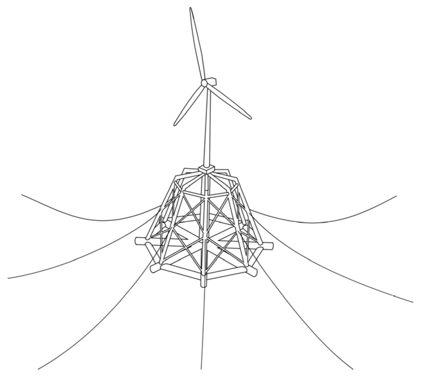
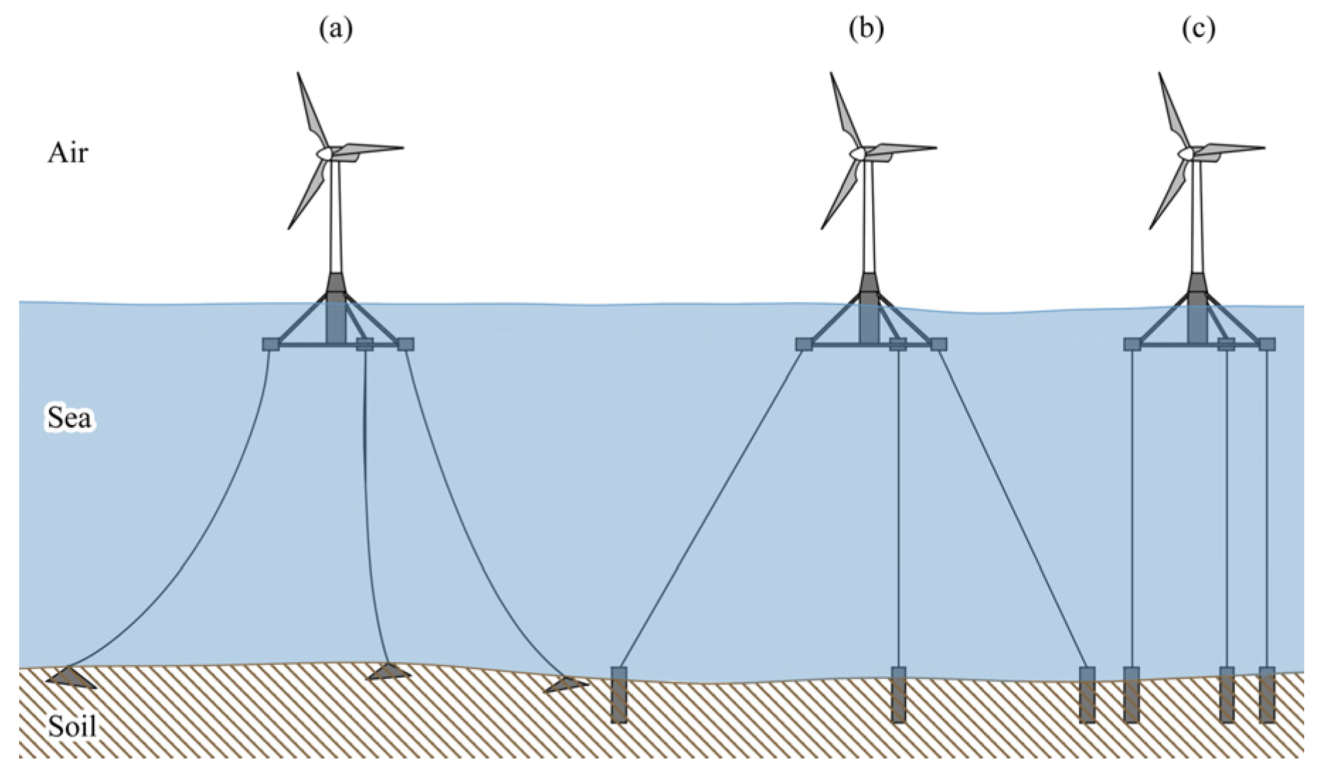
FOWT has multiple mooring types. Three common mooring types include catenary mooring, umbrella-type tension mooring, and vertical tension-leg mooring [26], as shown in Figure 5. Catenary mooring applies to shallow sea areas. It has the advantages of simple structure, easy maintenance, and replacement, but the stability of wind turbines is influenced by the hanging angle. Due to the long steel cables, wind turbines may develop great motion as a response to waves, and they are prone to suffering fatigue failures. Umbrella-type tension mooring applies to deep-sea areas. It has the advantages of a stable structure, but it has difficulty being influenced by the hanging angle and a decreasing mooring weight. However, the constrained tension of the mooring line mainly relies on the tensile deformation of cables rather than the dead loads of the hanging section. The constructed seabed anchoring device has to bear not only the horizontal tension but also great vertical tension, thus resulting in a high cost [27]. Vertical tension-leg mooring applies to deep-sea areas. It has the advantages of a simple structure and good float stability, but the cable is easily skewed and slides, thus requiring regular tension and adjustment. Moreover, the inherent frequency of tension legs is relatively high due to the tension state. The vortex-induced vibration and second-order low-frequency wave forces may cause high-frequency elastic vibration and fluttering of tension legs, which further cause fatigue damage [28].

3. Dynamics of Fixed OWT Foundations

A fixed offshore wind turbine is a major type of wind power generation equipment, and it has been applied to many offshore wind power fields. Despite their popularity, complicated loads in marine environments may affect the structure and operation of fixed offshore wind turbines, thus influencing their stability and reliability.

3.1. PSI Analysis

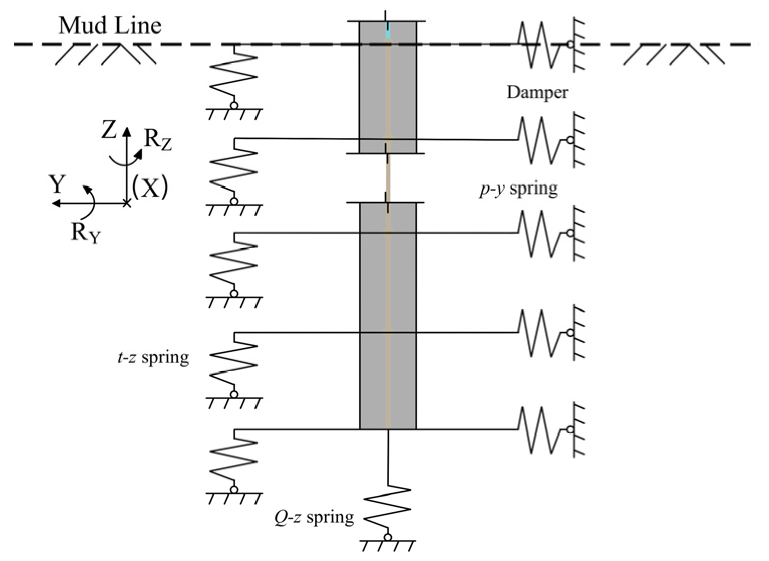
In the service life of fixed offshore wind turbines, the pile–soil interface bears substantial cyclic shear under the wind–wave-current coupling effect, thus resulting in the loosening of the surrounding soil mass. The PSI weakens continuously, thus influencing the dynamic responses of the whole wind turbine structure to operation and extreme loads. The p-y, t - z , and Q - z elastic models recommended in the specifications of the American Petroleum Institute (API) are widely used in the design of pile foundations in marine engineering. This method comprehensively considers the influences of soil nonlinearity, soil layer changes, and soil types. It should be noted, however, that the API p - y curve model was initially developed for small-diameter piles in the petroleum industry, and there are certain limitations when applied to the large-diameter monopiles commonly used in current offshore wind engineering. The model does not fully account for the differences in pile–soil interaction mechanisms between large- and small-diameter piles, which may lead to deviations in the prediction of soil reaction forces. As mentioned in Li et al. [29], their study deduced the soil reaction component functions of PSI to correct the subgrade reaction modulus in the p - y curve technique for monopile offshore wind systems, which also indirectly reflects the need for optimization of the API p - y curve in practical wind power scenarios.
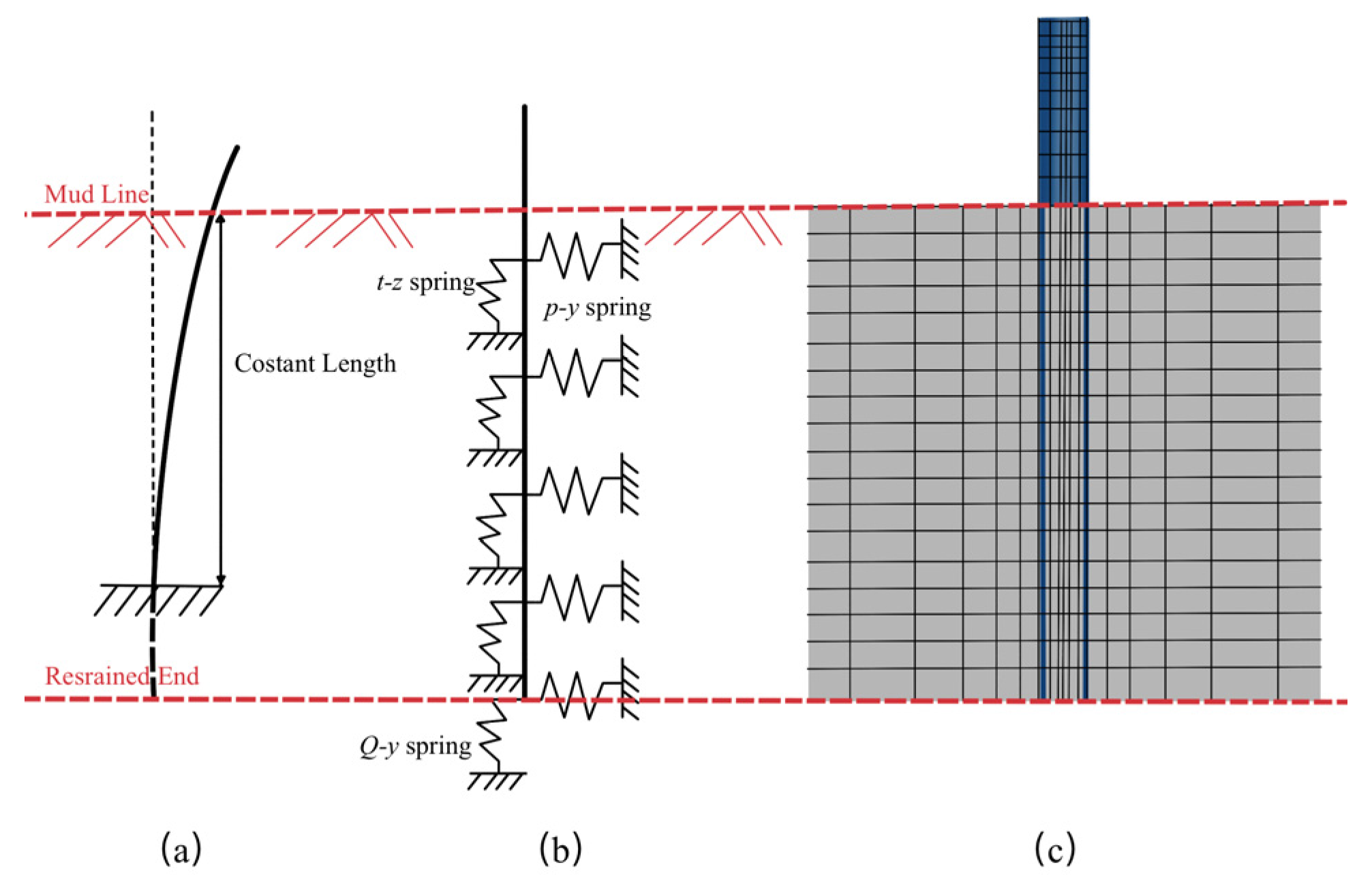
In the typical pile body response analysis, discrete non-coupled springs are usually added to the unit nodes to simulate the soil’s reaction force on the pile body [30], as shown in Figure 6. Under the coupled influence of vertical force, horizontal force, and bending moment at the pile head, the lateral and vertical reactions of the pile-side soil and the vertical reaction of the pile-end soil can be described by the p - y , t - z , and Q - z spring models, respectively [31].
The p - y relationships for sand may be approximated at depth z as follows:
P = A p t a n h k z A p y ,
where P is soil resistance in kN/m, y is soil deflection in m, A = 0.9 for cyclic loading, k is the initial modulus of subgrade reaction in kN/m3, determined as a function of internal friction angle, and p is the ultimate bearing capacity.
Accurate prediction of dynamic characteristics of OWTs has important significance to the safe and high-efficiency operation of OWTs [33]. In particular, attention should be paid to PSI modeling. The common foundation models include the apparent fixity model [34], distributed spring model [35], and the FE model of the soil–pile system [36]. These three types of foundation models are shown in Figure 7, and a comparison of their characteristics is presented in Table 6.
Long-term cyclic loading significantly affects the deflection and rotation of the pile head under the serviceability limit state [39]. Specifically, cyclic wind–wave loads cause continuous weakening of the PSI, which further leads to two key issues: accumulated rotation of the monopile and degradation of soil stiffness around the pile. These two issues will not only reduce the inherent frequency of the OWT system [40] but also increase the risk of exceeding the serviceability limit state, yet they are not fully addressed in traditional PSI models. Ren [41] and colleagues carried out a series of model tests to investigate the long-term PSI effect of OWTs in layered soils. To address the issues of cyclic loading, accumulated rotation, and stiffness degradation, alternative models and site-specific calibration are necessary. For example, the p-y curve correction method [29] and the OMA-based parameter identification method [42] can be used to address these issues, helping reduce the deviation of PSI modeling in practical engineering applications. Correcting the complex soil mass model [43], considering cyclic loads and the model involving PSI parameters and structural damping parameters, remains a significant challenge. Further breakthroughs in research are necessary.

3.2. Wind and Wave Load Analysis

In the field of offshore wind engineering, it is crucial to consider the effect of wind and wave loads on the foundation of wind turbines. In 2004, DNV released DNV-OS-J101 [44], the dedicated offshore wind standard. This standard incorporated wind and wave load analysis methods from offshore oil platforms while primarily adhering to the linear wave theory. In 2007, the revised version of this standard [45] recommended the use of nonlinear wave theory to calculate extreme loads. In 2011, experimental studies [46] discovered that breaking waves could induce a horizontal acceleration of over 0.5 g on offshore wind turbine towers, which was far beyond the predictions of the linear wave theory. This finding thus drew industry attention to the impact loads of breaking waves. These loads determine the stability and design of the structure and have a direct impact on the long-term performance and safety of offshore wind farms. Wind turbines and their foundations can experience intense dynamic responses, especially under extreme weather conditions. This interaction may cause liquefaction areas in the seabed foundation, with the maximum liquefaction depth reaching up to 2 m. At the same time, residual horizontal displacement at the top of the wind turbine may result in overall tilt, with the maximum tilt angle reaching up to 0.51 degrees [47]. Therefore, it is essential to fully consider the impact of wind and wave loads when designing and evaluating offshore wind farms to ensure the structure’s reliability and durability.
Present studies are endeavoring to investigate these intricate interactions. Chen et al. [48] endeavored to investigate the stability of OWT towers by incorporating wind and wave loads, ascertained by the FAST Version 7.0, into ABAQUS 2019. Nonetheless, this approach is excessively simplified and does not adequately represent the intricate interactions among waves, the seabed, and offshore wind energy. Cao et al. [49] employed analytical solutions to estimate wave loads, yet were unable to precisely capture their fluctuations temporally and spatially. Moreover, the research by T.S. Charlton and M. Rouainia [50] scrutinized the performance susceptibility of monopile foundations under extreme storm conditions utilizing a dynamic three-dimensional finite element model.
The wave impact load refers to the instant slamming forces caused by waves. The fixed offshore wind turbines installed in shallow regions experience highly variable hydrodynamic loads and breaking waves during operation. These conditions can cause wind turbine foundations to generate immediate responses, which may have potential impacts on the safety and stability of wind turbines [51]. In addition, the frequent and violent wave impacts may also cause fatigue damage and structural degradation of the foundation for a long period, thus making it easier to be eroded and broken by other external forces. Jose et al. [52] analyzed the effects of the wave-slamming loads by the empirical mode decomposition (EMD) and the frequency response function (FRF). Paulsen et al. [53] established a calculation formula for wave-slamming probability and slamming force onto the subgrade of OWTs through a physical model test.
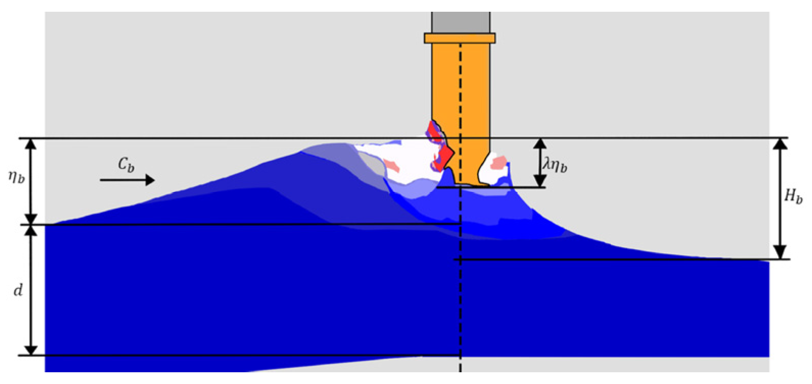
In addition, fixed offshore wind turbine foundations in deep offshore areas can interact with the seabed, which may strengthen the nonlinearity of waves, increase the likelihood of wave breaking, and have significant impacts on wind turbine foundations [54]. Lin and Hasan [55] simulated the impact of breaking waves onto the foundation of OWTs by using the computational fluid dynamics (CFD) model (Figure 8). Zhu et al. [56] analyzed slamming characteristics of breaking regular waves and irregular waves. A Gaussian distribution formula was proposed to fit the exceedance probability distribution of wave impact forces, along with a revised empirical formula for computing the wave-slamming coefficient for both regular and irregular waves in instances of monopile failure. Nonetheless, the influence of slamming vibrations on the structural integrity of stationary offshore wind turbine units continues to be ambiguous.

3.3. Seismic Analysis

For a fixed offshore wind turbine, an earthquake mainly causes vibration and stress on the foundation structure and threatens the stability and safety of the wind turbines. The 2011 Tohoku Earthquake, which caused tilting of a monopile-founded offshore wind turbine due to seismic seabed liquefaction, exposed the neglect of seismic-wave coupling effects in traditional designs and compelled the industry to re-evaluate seismic design standards [57]. Therefore, it is necessary to include seismic analyses in the design and construction stage of wind turbines to ensure that they can withstand seismic loads.
The International Electrotechnical Commission (IEC) has formulated international standards for the wind power industry, introducing three methodologies for simulating seismic responses: (1) the simplified method; (2) the time-domain analysis method; and (3) the structural response spectrum analysis method. In the simplified analysis of the single-degree-of-freedom system, the process exhibits high computational efficiency, attributable to the omission of time-domain analysis of seismic waves. During the simulation process, the wind turbine’s blades and nacelle are represented as concentrated loads atop the model tower [58], necessitating the full constraint of the model’s base node. However, this simplified method does not incorporate the higher-order modes that likewise influence the seismic load response of the wind turbine, resulting in comparatively lower simulation accuracy in applications involving medium-strength or flexible soil [59]. Conversely, the time-domain analysis method boasts superior simulation accuracy.
The finite element analysis framework of OWTs under seismic loads is shown in Figure 9 [60]. Wang et al. [61] studied seismic responses of 5 MW OWTs that considered nonlinear PSI and found that dynamic stiffness and damping both had significant influences on the seismic responses of OWTs. Panagoulias et al. [62] revealed that the plasticity index parameter of the clay layer exerts direct control over the hysteretic damping of soil materials and significantly impacts the transmission function of the input seismic motion. Notably, differences in OWTs’ seismic responses across operational, shutdown, and emergency shutdown states have also been identified, which underscores the importance of establishing an integrated analytical framework of comprehensive module of seabed seismic motion and the PSI equivalent coupling elastic boundary module that incorporates diverse operational states of OWTs [63].
Wave loads generate scouring action on the seabed near the fixed offshore wind turbine foundation. With the increase in flushing time, scour pits might be formed surrounding the foundation, thus making the support conditions of the foundation unstable [65]. Under seismic loads, these scour pits may make wind turbines generate greater dynamic responses, including increasing vibration amplitude and frequency changes [66]. While the current studies have contributed to our understanding of the impact of scour depth on seismic dynamic responses, there remains a deficiency in measurement data and detailed calculation models that incorporate various factors, such as the marine environment and soil properties.
Liquefaction itself remains the primary challenge for OWTs under seismic conditions, as earthquake-induced liquefaction reduces foundation bearing capacity, raising overturning risks and potential unit damage. A key limitation of current liquefaction analysis lies in the significant uncertainty in offshore seismic inputs. Unlike onshore scenarios, offshore seismic wave propagation is influenced by multi-layered media, leading to differences in wave attenuation, frequency content, and peak acceleration. However, most seismic input parameters in offshore wind standards are derived from onshore databases, with few site-specific offshore measurements. For instance, offshore seismic intensity is often determined using regional onshore zoning, failing to account for local marine geological features that amplify or dissipate seismic energy, introducing uncertainty into the initial conditions of liquefaction evaluation.
Compounding this uncertainty is the scarcity of large-scale validation data for liquefaction and post-liquefaction behavior [67,68]. Existing liquefaction-related experimental studies mostly rely on small-scale tests. While these tests provide valuable insights into liquefaction mechanisms, they still face challenges in fully replicating the stress state of full-scale offshore foundations, the complex soil-structure interaction process, and the complete liquefaction evolution law under actual marine conditions.

4. Dynamics of FOWT Foundations

Accurate hydrodynamic analysis of OWT systems under complicated environmental loads has been a key challenge in the research field of OWTs. Compared to inshore fixed OWTs, FOWTs also have to consider many influencing factors, such as radiated hydrodynamic loads caused by the motion of the support platform, additional hydrodynamic damping, and so on.
The motion of the FOWT foundation driven by wave forces is usually considered in four parts: ① wave frequency motion in consistency with the characteristic frequency of waves; ② drift motion under a constant force in second-order wave forces; ③ low-frequency slow drift motion caused by the frequency difference effect of waves; and ④ high-frequency springing motion caused by the frequency summation effect of waves. Under the effect of regular waves, the floating body may skew from the average position, except for swaying that is consistent with the wave frequency. Such skewing is the consequence of the second-order constant force. Under the effect of irregular waves, different frequency generations of different components may produce long-term drift motion [69].
Research experiences regarding floating platforms in the offshore oil field can provide references to study the hydrodynamic performances of the FOWT foundation. Common research methods include the Morison equation [70], the potential flow theory method, and computational fluid mechanics (CFD). All of these methods mainly originated from research methods of floating platforms in traditional marine projects. A commonly used and relatively simple approach that balances practicality and simplicity is as follows: For linear hydrodynamic problems, both the radiation problem and the diffraction problem [71] are solved based on potential flow theory. For the consideration and calculation of viscous drag loads, the Morison equation [72], which is extensively adopted in industry practice, is employed. By integrating the solutions from the aforementioned potential flow theory-based analysis and the Morison equation-derived viscous drag calculation, the total external loads acting on the platform can be expressed as follows:
F t = A ω q ¨ + R e A X ω , β e j ω t C m o o r + C r e s q B ω q ˙ + 1 2 ρ C D D v t , 0,0 q ˙ v t , 0,0 q ˙ ,
where F is the total external loads acting on the platform, excluding gravity; A is the added mass matrix; q ¨ is the second-order derivative of the system’s degree of freedom; t is the simulation time; A is the amplitude of the regular incident wave; X is the frequency and direction-dependent complex excitation force on the platform due to a unit wave amplitude; ω is the frequency of the incident wave; β is the propagation direction of the incident wave; e j ω t is the harmonic index; C m o o r is the linear restoring force matrix from all mooring lines; C r e s is the linear hydrostatic restoring force matrix from the horizontal plane area and the metacenter; ρ is the density of seawater, taken as 1.025 g / c m 3 ; C D is the coefficient of viscous drag; D is the diameter of the cylinder; v is the undisturbed fluid-particle velocity component of the platform, constituting the vector sum of wave-induced velocity and current velocity.

4.1. Motion Analysis of the Platform

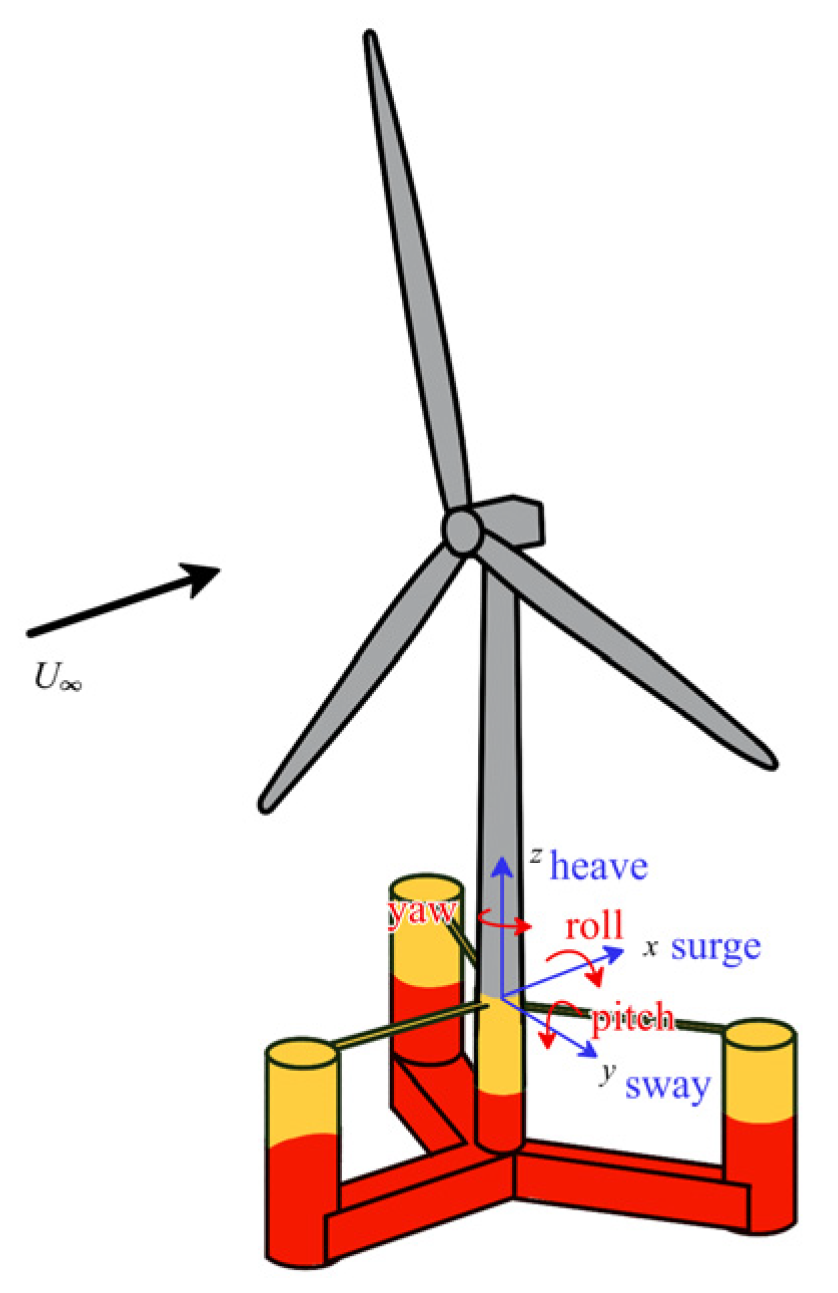
Early studies (2009–2015) verified the feasibility of floating wind turbines through the Hywind Demo project. However, limited by the modeling technology available at that time, the prediction of platform motion response was inaccurate [73]. The motion of offshore floating wind turbines’ foundations, with six degrees of freedom (DOF) (Figure 10), is more complex than that of onshore and fixed offshore wind turbines. This results in significant changes in relative wind speed and pronounced aerodynamic damping issues for floating wind turbines [74]. The aerodynamic and hydrodynamic damping of floating wind turbines significantly impacts the system response under individual wave and combined wind–wave conditions [75]. In some conditions, the influence of aerodynamic damping on the platform motion and power performance of floating wind turbines even exceeds that of hydrodynamic damping. Viscous damping, arising from fluid viscosity and flow separation around structures, remains a persistently challenging parameter to accurately represent. This is because viscous damping is highly sensitive to nonlinear flow effects, structural geometric details, and platform motion states. Existing empirical or semi-empirical models often simplify these factors, leading to difficulties in capturing the true viscous damping behavior across different operating scenarios.
The authors’ relevant studies indicate that [14], as an important environmental excitation, the aerodynamic load of the wind turbine plays a decisive role in the pitching motion of the floating platform. Further research by Bofeng Xu et al. [76] explored the impact of rotor tilt angle on the aerodynamic performance of downwind floating wind turbines during platform pitch motion. It is essential to analyze the dynamic safety caused by hurricanes, as most floating offshore wind turbines are located on hurricane paths. According to the authors’ relevant research [1], under typhoon conditions, the Spar platform exhibits superior overall performance in terms of motion responses across DOFs compared to the semi-submersible platform. Additionally, the order of magnitude of motion responses in directions such as surge and roll is close to that in sway and pitch directions, as shown in Figure 11. This implies that surge and roll also cannot be neglected under extreme wind speeds. Under extreme wind speeds, the water turbine is idling, which relatively increases the impact of hydrodynamic loads [77]. This significantly influences the movement of the floating wind turbine platform.
Optimizing the design of the FOWT foundation structure is one of the most effective ways to improve the stability and reliability of a floating foundation. The stability principle and geometric size are viewed as major factors that decide system stability. Different types of FOWT adopt different technological ideas for stability optimization according to their hydraulic stability characteristics and hydrodynamic characteristics. At present, there are two major means to optimize the semi-submersible foundation: increasing the natural period of motion in the vertical surface of the platform or increasing the relevant hydrodynamic viscous damping. Both goals could be realized by using a heave plate [78] and moonpools [79].
In addition to improving the hydrodynamic stability of the platform by increasing accessory structures, it is a powerful means to make innovative designs of a platform structure to improve the stability of the FOWT foundation. Increasing the spacing between columns has been identified as a cost-effective strategy to enhance both stability and hydrodynamic efficiency [80]. Jiale Li et al. [81] have proposed a concept of a multi-bucket foundation floating platform (MBFFP) for the simultaneous transport of multiple bucket foundation-tower-turbine (BFTT) units.
Active and passive control methods also serve as key pathways for mitigating platform motion-induced loads: Tomás-Rodríguez & Santos [82] proposed a hybrid system combining a tuned mass damper (TMD) and an inerter element. Velino et al. [83] developed a machine learning-optimized individual pitch control (IPC) strategy, which reduces the platform pitch amplitude and the foundation DEL.
Notably, the aforementioned control strategies primarily focus on regulating the platform motion of a single FOWT. However, at the wind farm scale, the platform motion of FOWTs also exhibits strong coupling with another type of active control strategy, namely wake steering. Although the core objective of wake steering is to reduce wake interference on downstream turbines, changes in aerodynamic force distribution can indirectly affect the stability of the FOWT’s own platform. Gebraad et al. [84] demonstrated via CFD simulations that a yaw angle of 5–20° induces slight roll fluctuations of the platform, which can be compensated by the controller. Howland et al. [85] pointed out that a yaw update period of 15–30 min matches the time scale of platform motion, avoiding excessive platform attitude adjustments. Doekemeijer et al. [86] conducted field experiments and observed that changes in the yaw angle will affect the horizontal force of the platform. Furthermore, the offshore experiments [87] showed that reasonable wake steering can reduce the sudden roll loads on downstream platforms caused by wake turbulence, decreasing the peak response of platform motion.

4.2. Hydroelastic Analysis

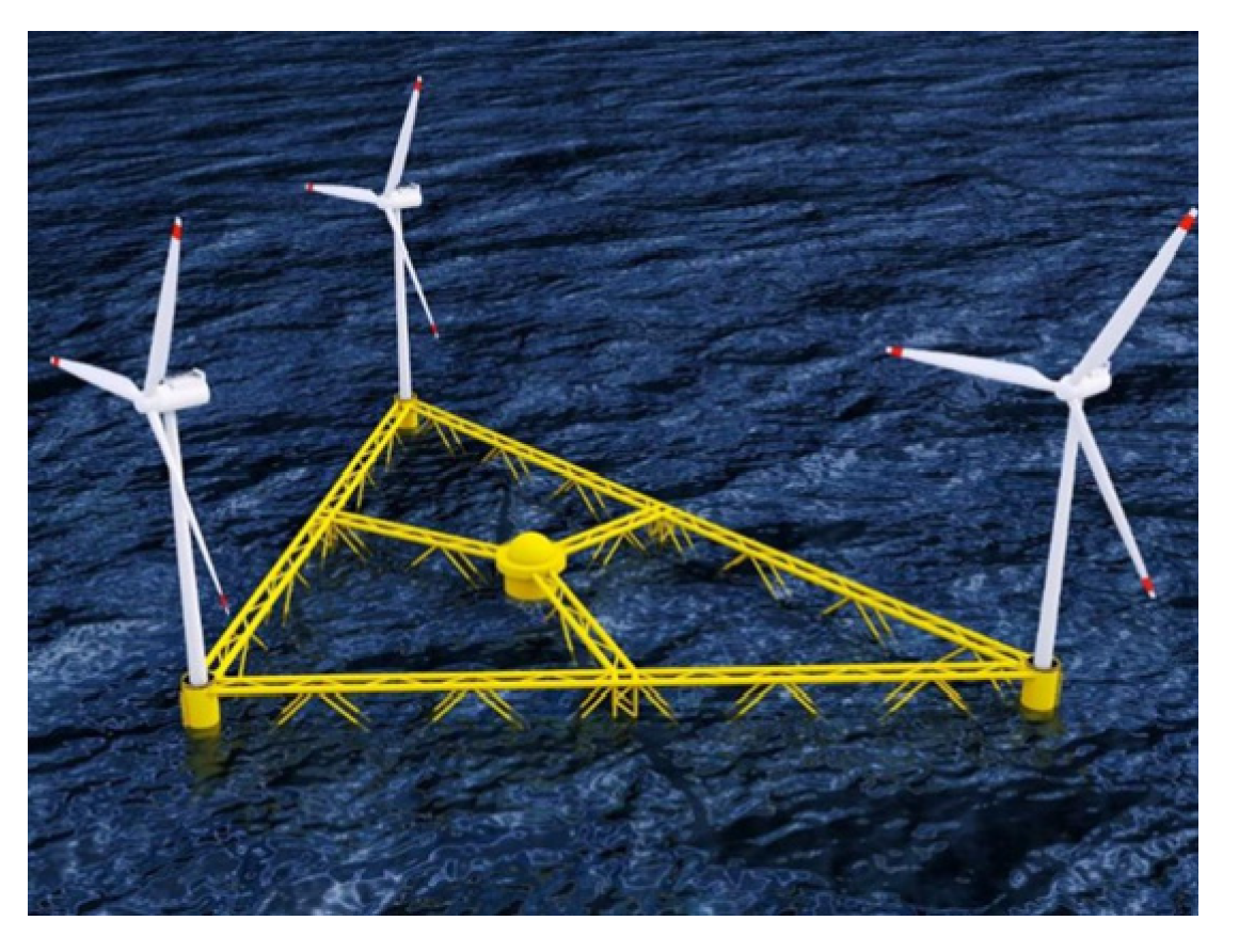
When the floating structure is ultra-large, the very large floating structure (VLFS) is far larger than the wavelength of sea waves. For VLFS, the rigid-body assumption no longer meets the required calculation accuracy, mainly because flexible deformation of the structure can no longer be neglected. On one hand, regular and irregular waves not only drive VLFS’s rigid motion but also induce significant deflection and vibration; such deformation must be considered in engineering analyses. On the other hand, the ratio of the structure’s stiffness to hydrodynamic loads decreases for VLFS. A lower stiffness-to-load ratio thus makes the structure more susceptible to noticeable flexible deformation under wave excitation. These characteristics mean the rigid-body assumption fails to capture key phenomena like springing and ringing. Both phenomena are closely tied to structural flexibility and directly affect the accuracy of VLFS’s motion, load, and stability evaluations. Typical VLFS examples include the floating multi-unit platform (Figure 12) and the floating platform of ultra-large wind turbines, summarized by Lamei and Hayatdavoodi [88]; these are examples of VLFS. Studying the interaction between such waves and structures is viewed as a hydroelastic problem.
Pertaining to offshore floating wind turbine units outfitted with VLFS, Li [89] suggests that accounting for the flexibility of the substructure leads to increased instability in the power production of the wind turbine units, with surges in instantaneous power output escalating by as much as 22.5%. In a word, the hydroelastic effects of floating multi-unit platforms and VLFS cannot be ignored. Nowadays, the deformation of a deformable body is usually described by the Rayleigh–Ritz method, finite segment method, finite element method, and modal analysis method. Based on the lumped-mass approach for slender marine structures and the frequency domain multi-bodies method, Li [89] constructed a hydroelastic model (Figure 13). This hydroelastic model is convenient for the aero-hydro-servo-elastic analysis of floating wind turbines. Borg et al. [90] introduced a method including the hydroelastic effect in time domain simulation and applied it to study the Spar platform supporting 10 MW wind turbines. Souza and Bachynski [91] took the hydroelastic interaction between flexible substructure and fluid into account during the dynamic simulation of FOWT. Leroy et al. [92] proposed a numerical simulation tool, WS_CN-FEM, which coupled a nonlinear potential flow solver and structural model based on modal superposition and applied it to a large-diameter monopile.
Beyond numerical simulation, Leroy et al. [93] designed a new experimental wind turbine model, which was used to study hydroelastic responses of large FOWTs under regular waves and extreme marine conditions. The platform model is made of a flexible backbone, reproducing the correct flexibility, and the light floaters fixed on it provide the correctly scaled geometry. However, in contrast to traditional marine floating structures, large-scale floating wind turbines, being the world’s largest rotating rigid–flexible coupling bodies, possess wind wheel aerodynamic loads that serve as one of the key factors influencing the dynamic behavior characteristics of the entire floating wind turbine system. The physical model test system, previously centered on simulating and evaluating hydrodynamic characteristics, is no longer sufficient to fulfill the novel requirements of integrated scale model tests for large-scale floating wind turbines.
In addition, existing studies have also proved that nonlinear hydrodynamics can excite abundant resonance responses [94]. Highly nonlinear hydroelastic responses were observed in irregular waves when high-order hydrodynamic loads excited the bending modal. In irregular wave conditions, such behavior was also caused by the strong nonlinear effect, thus resulting in spring or ring responses of the system [93]. This highlights the importance of nonlinear hydrodynamics in hydroelastic analysis of large floating wind turbines.

4.3. Dynamic Analysis of Mooring

Establishing an accurate dynamic analysis of the mooring system can offer guidance for optimizing the design of the system, improving wind resistance, and reducing structural vibration and fatigue. Compared with finite element analysis, the quasi-static method ignores the inertia force and hydrodynamic damping force of mooring lines [95].
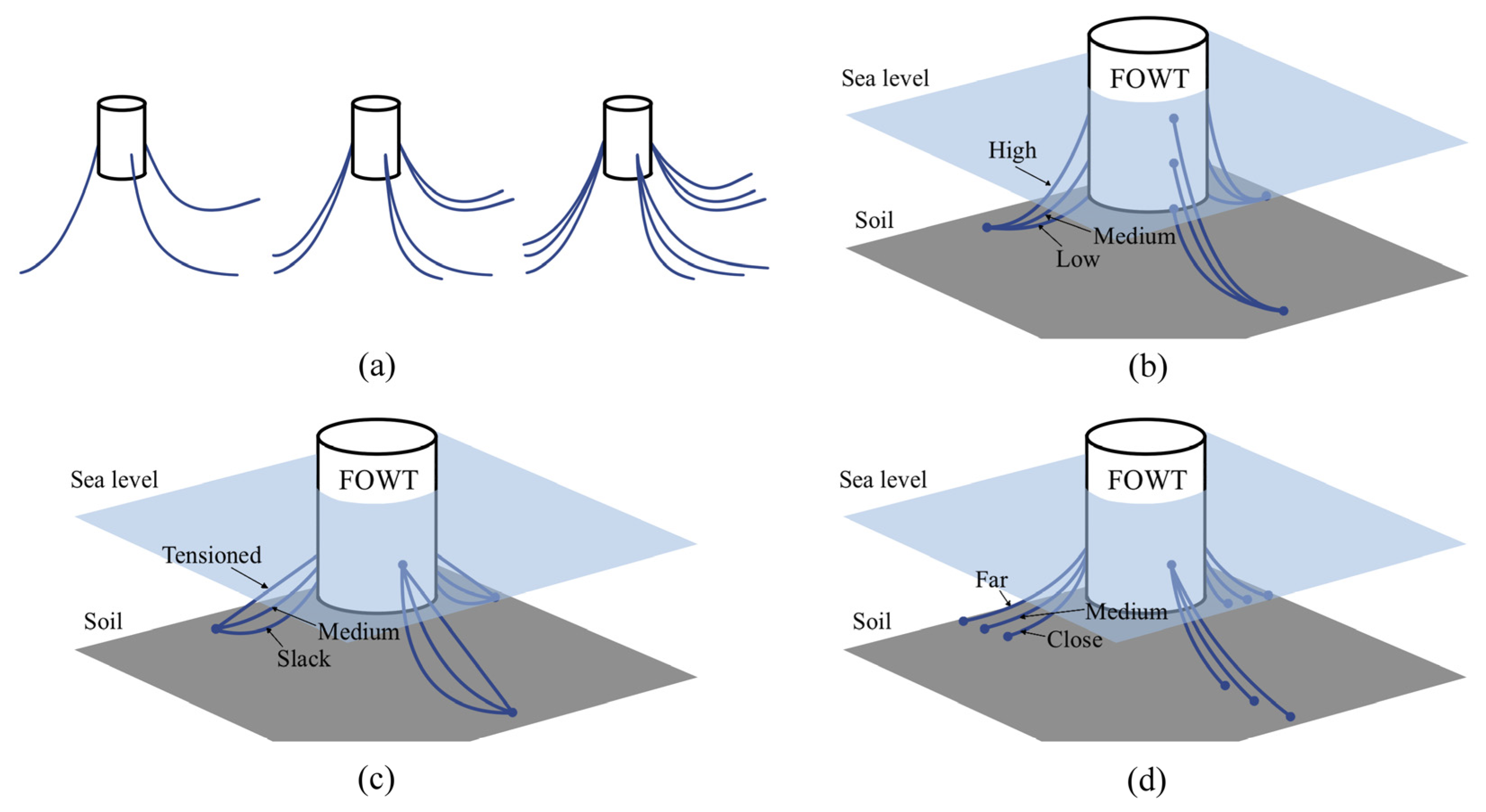
Deep studies on the characteristics and dynamic responses of mooring systems can provide reliable references for the design and improvement of mooring systems, thus enhancing their stability and sustainability. In their comparative analysis of various mooring configurations, Liu and Yu [96] revealed the impact of parameters, such as the diameter and length of mooring lines, on the system’s performance. Zhang et al. [97] analyzed the design principle of the mooring system of FOWTs. Different layouts of mooring lines are shown in Figure 14. It found that layout changes in mooring lines can influence surge and line tension directly, and upper positions of mooring lines can also influence pitch. Additionally, excessive tension makes mooring lines easily influenced by high-frequency waves and produces high-frequency resonance and even fatigue failures. The studies referenced above have conducted an analysis of a series of parameters with significant influence on the mooring system. However, certain design load conditions, such as the accidental limit state (ALS) and fatigue limit state (FLS), have not been taken into account.
As the trend towards deep-sea wind turbines progresses, FOWTs will be subjected to stronger cyclic wind and wave loads. This may cause severe fatigue damage at certain critical locations, potentially causing catastrophic failures. Common numerical assessment methods include the S-N and T-N curves [98]. However, fatigue assessment necessitates comprehensive dynamic analysis across diverse environmental scenarios, demanding high precision and complexity in numerical simulations. To ensure accurate predictions and reduce computational expenses, Xuan Li et al. [99] have employed the C-vine copula model and surrogate model to introduce a probabilistic approach for long-term fatigue damage assessment. Based on the above analysis, the load risk of the mooring system mainly stems from tension fluctuations and fatigue accumulation caused by the dynamic motion of the platform. Traditional passive designs struggle to adapt to load regulation requirements under complex sea conditions, while active control strategies provide a new approach for mooring load mitigation. The active platform repositioning strategy based on model predictive control (MPC) [100] can reduce the peak tension of mooring lines and still prevent mooring lines from entering the nonlinear elastic stage under extreme sea conditions.
Restoration performances of dynamic mooring lines present obvious hysteresis characteristics, which may produce profound effects on structural responses of FOWTs under environmental loads [101]. Owing to the hysteresis characteristics of restoration performances, the surge response of the platform under extreme wave loads exhibited a decrease compared to that under quasi-static conditions [102].

5. Conclusions

The dynamics of OWT foundations are unique and complicated due to the uniqueness of the structure and complexity of the external environment, facing a series of new problems and challenges. This article conducts a comprehensive review of state-of-the-art structural types and dynamic characteristics of OWT foundations. Research methods and progress regarding problems brought about by the environmental complexity of fixed and floating offshore wind turbine foundations are analyzed. Improvement spaces and improvement directions of relevant technologies are pointed out. Meanwhile, the integrated research roadmap for the dynamics of offshore wind turbine foundations covered in this article is shown in Figure 15.
The broad findings and recommendations are as follows.
  • Under current technological conditions, the disadvantages of fixed offshore wind turbines appear when water depth exceeds 60 m, and FOWTs show higher engineering economic efficiency. However, FOWT has not realized industrial operation, and the stand-alone capacity of OWTs is increasing continuously. Optimizing and breaking mechanical performances of fixed offshore wind turbine foundations have been one of the key directions for industrial and academic studies.
  • Uncertainty of soil properties may influence the dynamic response analysis of wind turbines significantly. Although there are many associated research achievements, it is still difficult to correct complicated soil models under cyclic loads and PSI parameters.
  • The study of wave loads on OWTs, although some progress has been achieved, still faces some problems that involve the uncertainty of wave prediction and the multi-field load-coupling effect of wind, sea waves, and ice floes.
  • Scouring and liquefaction are two major challenges against fixed wind turbine foundations under seismic effects. Studies about influences of scouring depth on dynamic responses are in the preliminary stage, lacking field verification and accurate evaluation. Liquefaction problems involve multi-field coupling effects, and it is difficult for experimental studies to simulate interactive effects in complicated marine environments completely.
  • The highly stable and highly reliable dynamics of floating foundations are key to guaranteeing the long-term safe and stable services of FOWTs. Exploring and breaking the mechanical properties of the FOWT foundation are core problems in industry and academic circles. With references to marine engineering technologies, FOWTs have optimized the reliability and comprehensive economic benefits of the system. The stability principle and geometric size are used as major factors, and different technological ideas of stability optimization are adopted.
  • Mechanical performances of foundations in academia and industry have insufficient understanding, resulting in disputes over structural safety and stability. Differences between FOWTs and traditional marine platforms in pneumatic loads should also be explored deeply.
  • Lack of large-scale experimental data, full-size experimental platforms on practical OTWs foundation, and complicated marine environmental simulation technology of experiments need further improvement.
  • Hydroelastic problems are an important problem that should be considered. Particularly, the mechanism and characteristics of hydroelastic behaviors in floating multi-unit platforms and VLFS have to be studied deeply.
  • Technical schemes to optimize stability and reliability and promote the sustainable development of offshore OWT foundations should be the focus of future research in this field.

Author Contributions

Conceptualization, X.C.; investigation, L.R. and M.C.; resources, X.C.; writing—original draft preparation, J.X. and H.Z.; writing—review and editing, H.W. and Z.X.; visualization, J.X.; supervision, X.C.; project administration, X.C.; funding acquisition, X.C. and H.W. All authors have read and agreed to the published version of the manuscript.

Funding

This research was funded by National Natural Science Foundation of China, grant number 52308498; Jiangsu Province Natural Science Foundation, grant number BK20220976; China Postdoctoral Science Foundation, grant number 2022M721002; the Key Laboratory of Ministry of Education for Coastal Disaster and the Protection, grant number 202207; and the Open Foundation of Jiangsu Wind Power Engineering Technology Center, grant number ZK22-03-05, which is gratefully acknowledged.

Data Availability Statement

No data was used for the research described in the article.

Conflicts of Interest

The authors declare no conflict of interest. The funders had no role in the design of the study; in the collection, analyses, or interpretation of data; in the writing of the manuscript; or in the decision to publish the results.

References

  1. Wu, X.; Hu, Y.; Li, Y.; Yang, J.; Duan, L.; Wang, T.; Adcock, T.; Jiang, Z.; Gao, Z.; Lin, Z. Foundations of Offshore Wind Turbines: A Review. Renew. Sustain. Energy Rev. 2019, 104, 379–393. [Google Scholar] [CrossRef]
  2. Jahani, K.; Langlois, R.G.; Afagh, F.F. Structural Dynamics of Offshore Wind Turbines: A Review. Ocean Eng. 2022, 251, 111136. [Google Scholar] [CrossRef]
  3. Musial, W.; Ram, B. Large-Scale Offshore Wind Power in the United States: Assessment of Opportunities and Barriers; National Renewable Energy Laboratory (NREL): Golden, CO, USA, 2010.
  4. Li, J.; Guo, Y.; Lian, J.; Wang, H. Mechanisms, Assessments, Countermeasures, and Prospects for Offshore Wind Turbine Foundation Scour Research. Ocean Eng. 2023, 281, 114893. [Google Scholar] [CrossRef]
  5. Leung, D.Y.; Yang, Y. Wind Energy Development and Its Environmental Impact: A Review. Renew. Sustain. Energy Rev. 2012, 16, 1031–1039. [Google Scholar] [CrossRef]
  6. Hou, G.; Xu, K.; Lian, J. A Review on Recent Risk Assessment Methodologies of Offshore Wind Turbine Foundations. Ocean Eng. 2022, 264, 112469. [Google Scholar] [CrossRef]
  7. Chen, P.; Jia, C.; Ng, C.; Hu, Z. Application of SADA Method on Full-Scale Measurement Data for Dynamic Responses Prediction of Hywind Floating Wind Turbines. Ocean Eng. 2021, 239, 109814. [Google Scholar] [CrossRef]
  8. Rezaei, F.; Contestabile, P.; Vicinanza, D.; Azzellino, A. Towards Understanding Environmental and Cumulative Impacts of Floating Wind Farms: Lessons Learned from the Fixed-Bottom Offshore Wind Farms. Ocean Coast. Manag. 2023, 243, 106772. [Google Scholar] [CrossRef]
  9. Sovacool, B.K.; Enevoldsen, P.; Koch, C.; Barthelmie, R.J. Cost Performance and Risk in the Construction of Offshore and Onshore Wind Farms. Wind Energy 2017, 20, 891–908. [Google Scholar] [CrossRef]
  10. Myhr, A.; Bjerkseter, C.; Ågotnes, A.; Nygaard, T.A. Levelised Cost of Energy for Offshore Floating Wind Turbines in a Life Cycle Perspective. Renew. Energy 2014, 66, 714–728. [Google Scholar] [CrossRef]
  11. Lu, F.; Long, K.; Zhang, C.; Zhang, J.; Tao, T. A Novel Design of the Offshore Wind Turbine Tripod Structure Using Topology Optimization Methodology. Ocean Eng. 2023, 280, 114607. [Google Scholar] [CrossRef]
  12. Zeng, X.; Shi, W.; Feng, X.; Shao, Y.; Li, X. Investigation of Higher-Harmonic Wave Loads and Low-Frequency Resonance Response of Floating Offshore Wind Turbine under Extreme Wave Groups. Mar. Struct. 2023, 89, 103401. [Google Scholar] [CrossRef]
  13. Ikoma, T.; Tan, L.; Moritsu, S.; Aida, Y.; Masuda, K. Motion Characteristics of a Barge-Type Floating Vertical-Axis Wind Turbine with Moonpools. Ocean Eng. 2021, 230, 109006. [Google Scholar] [CrossRef]
  14. Xie, J.; Wang, H.; Cai, X.; Xin, Z.; Ren, L.; Cai, M. Comprehensive Analysis of the Typhoon-Induced Impact on Large Offshore Wind Turbines Using Different Floating Platforms. Ocean Eng. 2025, 342, 122880. [Google Scholar] [CrossRef]
  15. Lian, J.; Ye, F.; Wang, P.; Guo, Y.; Wang, H.; Xiao, T.; Xiong, D. Integrated Transportation of Offshore Wind Turbine and Bucket Foundation Based on a U and K Shaped Assembled Platform. Ocean Eng. 2023, 275, 114096. [Google Scholar] [CrossRef]
  16. Johnston, B.; Foley, A.; Doran, J.; Littler, T. Levelised Cost of Energy, A Challenge for Offshore Wind. Renew. Energy 2020, 160, 876–885. [Google Scholar] [CrossRef]
  17. Kikuchi, Y.; Ishihara, T. Comparison of Dynamic Response and Levelized Cost of Energy on Three Platform Concepts of Floating Offshore Wind Turbine Systems. J. Phys. Conf. Ser. 2020, 1452, 012035. [Google Scholar] [CrossRef]
  18. Zhou, B.; Zheng, Z.; Hong, M.; Jin, P.; Wang, L.; Chen, F. Dynamic and Power Generation Features of A Wind–Wave Hybrid System Consisting of A Spar-Type Wind Turbine and An Annular Wave Energy Converter in Irregular Waves. China Ocean Eng. 2023, 37, 923–933. [Google Scholar] [CrossRef]
  19. Chen, M.; Xiao, P.; Zhou, H.; Li, C.B.; Zhang, X. Fully Coupled Analysis of an Integrated Floating Wind-Wave Power Generation Platform in Operational Sea-States. Front. Energy Res. 2022, 10, 931057. [Google Scholar] [CrossRef]
  20. Wang, K.; Li, Y.; Ong, M.C.; Wan, L.; Li, L.; Cheng, Z. Extreme Responses of An Integrated System with A Semi-Submersible Wind Turbine and Four Torus-Shaped Wave Energy Converters in Different Survival Modes. China Ocean Eng. 2024, 38, 877–892. [Google Scholar] [CrossRef]
  21. Chen, Z.; Yu, J.; Sun, J.; Tan, M.; Yang, S.; Ying, Y.; Qian, P.; Zhang, D.; Si, Y. Load Reduction of Semi-Submersible Floating Wind Turbines by Integrating Heaving-Type Wave Energy Converters with Bang-Bang Control. Front. Energy Res. 2022, 10, 929307. [Google Scholar] [CrossRef]
  22. Petracca, E.; Faraggiana, E.; Ghigo, A.; Sirigu, M.; Bracco, G.; Mattiazzo, G. Design and Techno-Economic Analysis of a Novel Hybrid Offshore Wind and Wave Energy System. Energies 2022, 15, 2739. [Google Scholar] [CrossRef]
  23. Jin, J.; Su, B.; Dou, R.; Luan, C.; Li, L.; Nygaard, I.; Fonseca, N.; Gao, Z. Numerical Modelling of Hydrodynamic Responses of Ocean Farm 1 in Waves and Current and Validation against Model Test Measurements. Mar. Struct. 2021, 78, 103017. [Google Scholar] [CrossRef]
  24. Lei, Y.; Zheng, X.Y.; Li, W.; Zheng, H.; Zhang, Q.; Zhao, S.; Cai, X.; Ci, X.; He, Q. Experimental Study of the State-of-the-Art Offshore System Integrating a Floating Offshore Wind Turbine with a Steel Fish Farming Cage. Mar. Struct. 2021, 80, 103076. [Google Scholar] [CrossRef]
  25. Serpetti, N.; Benjamins, S.; Brain, S.; Collu, M.; Harvey, B.J.; Heymans, J.J.; Hughes, A.D.; Risch, D.; Rosinski, S.; Waggitt, J.J.; et al. Modeling Small Scale Impacts of Multi-Purpose Platforms: An Ecosystem Approach. Front. Mar. Sci. 2021, 8, 694013. [Google Scholar] [CrossRef]
  26. Xu, H.; Rui, S.; Shen, K.; Jiang, L.; Zhang, H.; Teng, L. Shared Mooring Systems for Offshore Floating Wind Farms: A Review. Energy Rev. 2024, 3, 100063. [Google Scholar] [CrossRef]
  27. Pillai, A.C.; Gordelier, T.J.; Thies, P.R.; Cuthill, D.; Johanning, L. Anchor Loads for Shallow Water Mooring of a 15 MW Floating Wind Turbine—Part II: Synthetic and Novel Mooring Systems. Ocean Eng. 2022, 266, 112619. [Google Scholar] [CrossRef]
  28. Rongé, É.; Peyrard, C.; Venugopal, V.; Xiao, Q.; Johanning, L.; Benoit, M. Evaluation of Second and Third-Order Numerical Wave-Loading Models for Floating Offshore Wind TLPs. Ocean Eng. 2023, 288, 116064. [Google Scholar] [CrossRef]
  29. Li, X.; Dai, G.; Zhu, M.; Wang, L.; Liu, H. A Simplified Method for Estimating the Initial Stiffness of Monopile—Soil Interaction Under Lateral Loads in Offshore Wind Turbine Systems. China Ocean Eng. 2023, 37, 165–174. [Google Scholar] [CrossRef]
  30. Belabed, Z.; Tounsi, A.; Bousahla, A.A.; Tounsi, A.; Bourada, M.; Al-Osta, M.A. Free Vibration Analysis of Bi-Directional Functionally Graded Beams Using a Simple and Efficient Finite Element Model. Struct. Eng. Mech. 2024, 90, 233–252. [Google Scholar]
  31. Dauji, S. Axial Capacity of FRP Reinforced Concrete Columns: Empirical, Neural and Tree Based Methods. Struct. Eng. Mech. 2024, 89, 283–300. [Google Scholar]
  32. Shi, S.; Zhai, E.; Xu, C.; Iqbal, K.; Sun, Y.; Wang, S. Influence of Pile-Soil Interaction on Dynamic Properties and Response of Offshore Wind Turbine with Monopile Foundation in Sand Site. Appl. Ocean Res. 2022, 126, 103279. [Google Scholar] [CrossRef]
  33. Xie, S.; Gao, J.; Li, Y.; Jiang, S.; Zhang, C.; He, J. Aero-Hydro-Elastic-Servo Modeling and Dynamic Response Analysis of A Monopile Offshore Wind Turbine Under Different Operating Scenarios. China Ocean Eng. 2024, 38, 379–393. [Google Scholar] [CrossRef]
  34. Seed, H.B.; Lymon, C.; Reese, A.M.A. The Action of Soft Clay along Friction Piles. Trans. Am. Soc. Civ. Eng. 1957, 122, 731–754. [Google Scholar] [CrossRef]
  35. Matlock, H. Correlation for Design of Laterally Loaded Piles in Soft Clay. In Proceedings of the Offshore Technology Conference, Huston, TX, USA, 21–23 April 1970; p. OTC-1204. [Google Scholar]
  36. Galvín, P.; Romero, A.; Solís, M.; Domínguez, J. Dynamic Characterisation of Wind Turbine Towers Account for a Monopile Foundation and Different Soil Conditions. Struct. Infrastruct. Eng. 2017, 13, 942–954. [Google Scholar] [CrossRef]
  37. Yang, S.; Deng, X.; Yang, J. Modeling of Soil-Pile-Structure Interaction for Dynamic Response of Standalone Wind Turbines. Renew. Energy 2022, 186, 394–410. [Google Scholar] [CrossRef]
  38. Depina, I.; Le, T.M.H.; Eiksund, G.; Benz, T. Behavior of Cyclically Loaded Monopile Foundations for Offshore Wind Turbines in Heterogeneous Sands. Comput. Geotech. 2015, 65, 266–277. [Google Scholar] [CrossRef]
  39. Ma, H.; Yang, J.; Chen, L. Numerical Analysis of the Long-Term Performance of Offshore Wind Turbines Supported by Monopiles. Ocean Eng. 2017, 136, 94–105. [Google Scholar] [CrossRef]
  40. Yi, J.-H.; Kim, S.-B.; Yoon, G.-L.; Andersen, L.V. Natural Frequency of Bottom-Fixed Offshore Wind Turbines Considering Pile-Soil-Interaction with Material Uncertainties and Scouring Depth. Wind Struct. 2015, 21, 625–639. [Google Scholar] [CrossRef]
  41. Ren, X.; Xu, Y.; Shen, T.; Wang, Y.; Bhattacharya, S. Support Condition Monitoring of Monopile-Supported Offshore Wind Turbines in Layered Soil Based on Model Updating. Mar. Struct. 2023, 87, 103342. [Google Scholar] [CrossRef]
  42. Shirzadeh, R.; Devriendt, C.; Bidakhvidi, M.A.; Guillaume, P. Experimental and Computational Damping Estimation of an Offshore Wind Turbine on a Monopile Foundation. J. Wind Eng. Ind. Aerodyn. 2013, 120, 96–106. [Google Scholar] [CrossRef]
  43. Yeter, B.; Garbatov, Y.; Soares, C.G. Uncertainty Analysis of Soil-Pile Interactions of Monopile Offshore Wind Turbine Support Structures. Appl. Ocean Res. 2019, 82, 74–88. [Google Scholar] [CrossRef]
  44. DNV-OS-J101; Offshore Standard Design of Offshore Wind Turbine Structures. Det Norske Veritas: Høvik, Norway, 2004.
  45. Wedel-Heinen, J.; Ronold, K.O.; Madsen, P.H. Revision of DNV Design Standard for Offshore Wind Turbine Structures. In Proceedings of the 26th International Conference on Offshore Mechanics and Arctic Engineering, San Diego, CA, USA, 10–15 June 2007; Volume 42711, pp. 433–439. [Google Scholar]
  46. de Ridder, E.J.; Aalberts, P.; van den Berg, J.; Buchner, B.; Peeringa, J. The Dynamic Response of an Offshore Wind Turbine with Realistic Flexibility to Breaking Wave Impact. In Proceedings of the 30th International Conference on Ocean, Offshore and Arctic Engineering, Rotterdam, The Netherlands, 19–24 June 2011; Volume 44373, pp. 543–552. [Google Scholar]
  47. Yu, D.; Ye, J.; Yin, C. Dynamics of Offshore Wind Turbine and Its Seabed Foundation under Combined Wind-Wave Loading. Ocean Eng. 2023, 286, 115624. [Google Scholar] [CrossRef]
  48. Chen, D.; Gao, P.; Huang, S.; Li, C.; Yu, X. Static and Dynamic Loading Behavior of a Hybrid Foundation for Offshore Wind Turbines. Mar. Struct. 2020, 71, 102727. [Google Scholar] [CrossRef]
  49. Cao, G.; Chen, Z.; Wang, C.; Ding, X. Dynamic Responses of Offshore Wind Turbine Considering Soil Nonlinearity and Wind-Wave Load Combinations. Ocean Eng. 2020, 217, 108155. [Google Scholar] [CrossRef]
  50. Charlton, T.S.; Rouainia, M. Geotechnical Fragility Analysis of Monopile Foundations for Offshore Wind Turbines in Extreme Storms. Renew. Energy 2022, 182, 1126–1140. [Google Scholar] [CrossRef]
  51. Yang, J.; Liu, J.; Xie, J. A Hybrid-Separate Strategy for Force Identification of the Nonlinear Structure under Impact Excitation. Struct. Eng. Mech. 2023, 85, 119–133. [Google Scholar]
  52. Jose, J.; Podrazka, O.; Obhrai, C.; Gudmestad, O.T.; Cieslikiewicz, W. Methods for Analysing Wave Slamming Loads on Truss Structures Used in Offshore Wind Applications Based on Experimental Data. Int. J. Offshore Polar Eng. 2016, 26, 100–108. [Google Scholar] [CrossRef]
  53. Paulsen, B.T.; de Sonneville, B.; van der Meulen, M.; Jacobsen, N.G. Probability of Wave Slamming and the Magnitude of Slamming Loads on Offshore Wind Turbine Foundations. Coast. Eng. 2019, 143, 76–95. [Google Scholar] [CrossRef]
  54. Wei, C.; Yu, S.; Du, J.; Wang, W. Model Test Method for Dynamic Responses of Bridge Towers Subjected to Waves. Struct. Eng. Mech. 2023, 86, 705–714. [Google Scholar]
  55. Lin, Y.-H.; Hasan, A.D. Transient Analysis of the Slamming Wave Load on an Offshore Wind Turbine Foundation Generated by Different Types of Breaking Waves. J. Renew. Sustain. Energy 2022, 14, 053302. [Google Scholar] [CrossRef]
  56. Zhu, J.; Gao, Y.; Wang, L.; Li, W. Experimental Investigation of Breaking Regular and Irregular Waves Slamming on an Offshore Monopile Wind Turbine. Mar. Struct. 2022, 86, 103270. [Google Scholar] [CrossRef]
  57. Bhattacharya, S.; Goda, K. Use of Offshore Wind Farms to Increase Seismic Resilience of Nuclear Power Plants. Soil Dyn. Earthq. Eng. 2016, 80, 65–68. [Google Scholar] [CrossRef]
  58. Parate, K.; Kumbhar, O.; Kumar, R. Simplified Beam-Column Joint Model for Reinforced Concrete Moment Resisting Frames. Struct. Eng. Mech. 2024, 89, 77–91. [Google Scholar]
  59. Luco, J.E. Soil-Structure Interaction Effects on the Seismic Response of Tall Chimneys. Soil Dyn. Earthq. Eng. 1986, 5, 170–177. [Google Scholar] [CrossRef]
  60. Xi, R.; Xu, C.; Du, X.; Naggar, M.H.E.; Wang, P.; Liu, L.; Zhai, E. Framework for Dynamic Response Analysis of Monopile Supported Offshore Wind Turbine Excited by Combined Wind-Wave-Earthquake Loading. Ocean Eng. 2022, 247, 110743. [Google Scholar] [CrossRef]
  61. Wang, P.; Xu, Y.; Zhang, X.; Xi, R.; Du, X. A Substructure Method for Seismic Responses of Offshore Wind Turbine Considering Nonlinear Pile-Soil Dynamic Interaction. Soil Dyn. Earthq. Eng. 2021, 144, 106684. [Google Scholar] [CrossRef]
  62. Panagoulias, S.; de Winter, C.; Navalkar, S.T.; Nernheim, A. Sensitivity of the Seismic Response of Monopile-Supported Offshore Wind Turbines to Soil Variability. Ocean Eng. 2023, 268, 113545. [Google Scholar] [CrossRef]
  63. Liu, Y.; Wang, W.; Shi, W.; Li, X.; Li, Y. Dynamic Responses of Monopile Wind Turbine with Coupled Spring Boundaries in Bed Rock-Soil-Seawater Offshore Site under Offshore Ground Motions. Soil Dyn. Earthq. Eng. 2022, 158, 107311. [Google Scholar] [CrossRef]
  64. Ju, S.-H.; Huang, Y.-C. Analyses of Offshore Wind Turbine Structures with Soil-Structure Interaction under Earthquakes. Ocean Eng. 2019, 187, 106190. [Google Scholar] [CrossRef]
  65. Kaynia, A.M. Seismic Considerations in Design of Offshore Wind Turbines. Soil Dyn. Earthq. Eng. 2019, 124, 399–407. [Google Scholar] [CrossRef]
  66. Gao, B.; Ye, G.; Zhang, Q.; Xie, Y.; Yan, B. Numerical Simulation of Suction Bucket Foundation Response Located in Liquefiable Sand under Earthquakes. Ocean Eng. 2021, 235, 109394. [Google Scholar] [CrossRef]
  67. Ko, Y.-Y.; Li, Y.-T. Response of a Scale-model Pile Group for a Jacket Foundation of an Offshore Wind Turbine in Liquefiable Ground during Shaking Table Tests. Earthq. Eng. Struct. Dyn. 2020, 49, 1682–1701. [Google Scholar] [CrossRef]
  68. Hong-yan, D.; Jing-yi, L.I.; Cong-huan, L.E.; Chen, P.A.N.; Pu-yang, Z. Shaking Table Tests of Four-Bucket Jacket Foundation for Offshore Wind Turbines. China Ocean Eng. 2022, 36, 849–858. [Google Scholar] [CrossRef]
  69. Wang, L.; Robertson, A.; Kim, J.; Jang, H.; Shen, Z.-R.; Koop, A.; Bunnik, T.; Yu, K. Validation of CFD Simulations of the Moored DeepCwind Offshore Wind Semisubmersible in Irregular Waves. Ocean Eng. 2022, 260, 112028. [Google Scholar] [CrossRef]
  70. Siegerstetter, L.A.; Kleinschroth, A. Wave Forces on Vertical Cylinders as a Basis for the Design of Offshore Structures. Appl. Math. Model. 1976, 1, 119–124. [Google Scholar] [CrossRef]
  71. Jonkman, J.M. Dynamics Modeling and Loads Analysis of an Offshore Floating Wind Turbine; University of Colorado: Boulder, CO, USA, 2007; ISBN 0-549-31549-7. [Google Scholar]
  72. Morison, J.R.; Johnson, J.W.; Schaaf, S.A. The Force Exerted by Surface Waves on Piles. J. Pet. Technol. 1950, 2, 149–154. [Google Scholar] [CrossRef]
  73. Skaare, B.; Nielsen, F.G.; Hanson, T.D.; Yttervik, R.; Havmøller, O.; Rekdal, A. Analysis of Measurements and Simulations from the Hywind Demo Floating Wind Turbine. Wind Energy 2015, 18, 1105–1122. [Google Scholar] [CrossRef]
  74. Micallef, D.; Rezaeiha, A. Floating Offshore Wind Turbine Aerodynamics: Trends and Future Challenges. Renew. Sustain. Energy Rev. 2021, 152, 111696. [Google Scholar] [CrossRef]
  75. Tian, W.; Wang, Y.; Shi, W.; Michailides, C.; Wan, L.; Chen, M. Numerical Study of Hydrodynamic Responses for a Combined Concept of Semisubmersible Wind Turbine and Different Layouts of a Wave Energy Converter. Ocean Eng. 2023, 272, 113824. [Google Scholar] [CrossRef]
  76. Xu, B.; Kang, H.; Shen, X.; Li, Z.; Cai, X.; Hu, Z. Aerodynamic Analysis of a Downwind Offshore Floating Wind Turbine with Rotor Uptilt Angles in Platform Pitching Motion. Ocean Eng. 2023, 281, 114951. [Google Scholar] [CrossRef]
  77. Kang, T.-W.; Yun, J.-H.; Noh, H.-J.; Kim, E.; Yang, H.-I. Analysis of Contribution of Full Summation Hydrodynamic Load to Dynamic Response of Floating Offshore Wind Turbine Structure Operating in Extreme Environments. Int. J. Precis. Eng. Manuf. Green Technol. 2023, 10, 547–565. [Google Scholar] [CrossRef]
  78. Mello, P.C.; Malta, E.B.; da Silva, R.O.P.; Candido, M.H.O.; do Carmo, L.H.S.; Alberto, I.F.; Franzini, G.R.; Simos, A.N.; Suzuki, H.; Gonçalves, R.T. Influence of Heave Plates on the Dynamics of a Floating Offshore Wind Turbine in Waves. J. Mar. Sci. Technol. 2021, 26, 190–200. [Google Scholar] [CrossRef]
  79. Tan, L.; Ikoma, T.; Aida, Y.; Masuda, K. Mean Wave Drift Forces on a Barge-Type Floating Wind Turbine Platform with Moonpools. J. Mar. Sci. Eng. 2021, 9, 709. [Google Scholar] [CrossRef]
  80. Bai, H.; Zhang, M.; Yuan, W.; Xu, K. Conceptual Design, Parameter Optimization and Performance Investigation of a 10MW Semi-Submersible Floating Wind Turbine in Shallow Water. Ocean Eng. 2023, 281, 114895. [Google Scholar] [CrossRef]
  81. Li, J.; Lian, J.; Guo, Y.; Wang, H. Concept Design and Floating Installation Method Study of Multi-Bucket Foundation Floating Platform for Offshore Wind Turbines. Mar. Struct. 2024, 93, 103541. [Google Scholar] [CrossRef]
  82. Tomás-Rodríguez, M.; Santos, M. Modelling and Control of Floating Offshore Wind Turbines. RIAI—Rev. Iberoam. Autom. Inform. Ind. 2019, 16, 381–390. [Google Scholar]
  83. Velino, J.; Kang, S.; Kane, M.B. Machine Learning Control for Floating Offshore Wind Turbine Individual Blade Pitch Control. J. Comput. Civ. Eng. 2022, 36, 6. [Google Scholar] [CrossRef]
  84. Gebraad, P.M.O.; Teeuwisse, F.W.; Wingerden, J.W.; Fleming, P.A.; Ruben, S.D.; Marden, J.R.; Pao, L.Y. Wind Plant Power Optimization through Yaw Control Using a Parametric Model for Wake Effects—A CFD Simulation Study. Wind Energy 2016, 19, 95–114. [Google Scholar] [CrossRef]
  85. Howland, M.F.; Ghate, A.S.; Quesada, J.B.; Pena Martinez, J.J.; Zhong, W.; Larranaga, F.P.; Lele, S.K.; Dabiri, J.O. Optimal Closed-Loop Wake Steering—Part 2: Diurnal Cycle Atmospheric Boundary Layer Conditions. Wind Energy Sci. 2022, 7, 345–365. [Google Scholar] [CrossRef]
  86. Doekemeijer, B.M.; Kern, S.; Maturu, S.; Kanev, S.; Salbert, B.; Schreiber, J.; Campagnolo, F.; Bottasso, C.L.; Schuler, S.; Wilts, F.; et al. Field Experiment for Open-Loop Yaw-Based Wake Steering at a Commercial Onshore Wind Farm in Italy. Wind Energy Sci. 2021, 6, 159–176. [Google Scholar] [CrossRef]
  87. Fleming, P.A.; Gebraad, P.M.O.; Lee, S.; van Wingerden, J.-W.; Johnson, K.; Churchfield, M.; Michalakes, J.; Spalart, P.; Moriarty, P. Evaluating Techniques for Redirecting Turbine Wakes Using SOWFA. Renew. Energy 2014, 70, 211–218. [Google Scholar] [CrossRef]
  88. Lamei, A.; Hayatdavoodi, M. On Motion Analysis and Elastic Response of Floating Offshore Wind Turbines. J. Ocean Eng. Mar. Energy 2020, 6, 71–90. [Google Scholar] [CrossRef]
  89. Li, L. Full-Coupled Analysis of Offshore Floating Wind Turbine Supported by Very Large Floating Structure with Consideration of Hydroelasticity. Renew. Energy 2022, 189, 790–799. [Google Scholar] [CrossRef]
  90. Borg, M.; Hansen, A.M.; Bredmose, H. Floating Substructure Flexibility of Large-Volume 10MW Offshore Wind Turbine Platforms in Dynamic Calculations. J. Phys. Conf. Ser. 2016, 753, 082024. [Google Scholar] [CrossRef]
  91. Silva de Souza, C.E.; Bachynski, E.E. Effects of Hull Flexibility on the Structural Dynamics of a Tension Leg Platform Floating Wind Turbine. J. Offshore Mech. Arct. Eng. 2019, 142, 011903. [Google Scholar] [CrossRef]
  92. Mantadakis, N.; Loukogeorgaki, E.; Karimirad, M. Accounting for Hydroelasticity in the Analysis of Offshore Wind Turbine Spar-Type Platforms. In Proceedings of the 29th International Ocean and Polar Engineering Conference, Honolulu, HI, USA, 16–21 June 2019; p. ISOPE-I. [Google Scholar]
  93. Leroy, V.; Delacroix, S.; Merrien, A.; Bachynski-Polić, E.E.; Gilloteaux, J.-C. Experimental Investigation of the Hydro-Elastic Response of a Spar-Type Floating Offshore Wind Turbine. Ocean Eng. 2022, 255, 111430. [Google Scholar] [CrossRef]
  94. Wang, H.; Ke, S.T.; Wang, T.G.; Zhu, S.Y. Typhoon-Induced Vibration Response and the Working Mechanism of Large Wind Turbine Considering Multi-Stage Effects. Renew. Energy 2020, 153, 740–758. [Google Scholar] [CrossRef]
  95. Zhao, Z.; Li, X.; Wang, W.; Shi, W. Analysis of Dynamic Characteristics of an Ultra-Large Semi-Submersible Floating Wind Turbine. J. Mar. Sci. Eng. 2019, 7, 169. [Google Scholar] [CrossRef]
  96. Liu, B.; Yu, J. Effect of Mooring Parameters on Dynamic Responses of a Semi-Submersible Floating Offshore Wind Turbine. Sustainability 2022, 14, 14012. [Google Scholar] [CrossRef]
  97. Zhang, H.; Wang, H.; Cai, X.; Xie, J.; Wang, Y.; Zhang, N. Novel Method for Designing and Optimising the Floating Platforms of Offshore Wind Turbines. Ocean Eng. 2022, 266, 112781. [Google Scholar] [CrossRef]
  98. Barrera, C.; Battistella, T.; Guanche, R.; Losada, I.J. Mooring System Fatigue Analysis of a Floating Offshore Wind Turbine. Ocean Eng. 2020, 195, 106670. [Google Scholar] [CrossRef]
  99. Li, X.; Zhang, W. Long-Term Fatigue Damage Assessment for a Floating Offshore Wind Turbine under Realistic Environmental Conditions. Renew. Energy 2020, 159, 570–584. [Google Scholar] [CrossRef]
  100. Jard, T.; Snaiki, R. Real-Time Repositioning of Floating Wind Turbines Using Model Predictive Control for Position and Power Regulation. Wind 2023, 3, 131–150. [Google Scholar] [CrossRef]
  101. Zhang, Y.; Shi, W.; Li, D.; Li, X.; Duan, Y. Development of a Numerical Mooring Line Model for a Floating Wind Turbine Based on the Vector Form Intrinsic Finite Element Method. Ocean Eng. 2022, 253, 111354. [Google Scholar] [CrossRef]
  102. Chen, W.; Guo, S.; Li, Y.; Shen, Y. Impacts of Mooring-Lines Hysteresis on Dynamic Response of Spar Floating Wind Turbine. Energies 2021, 14, 2109. [Google Scholar] [CrossRef]
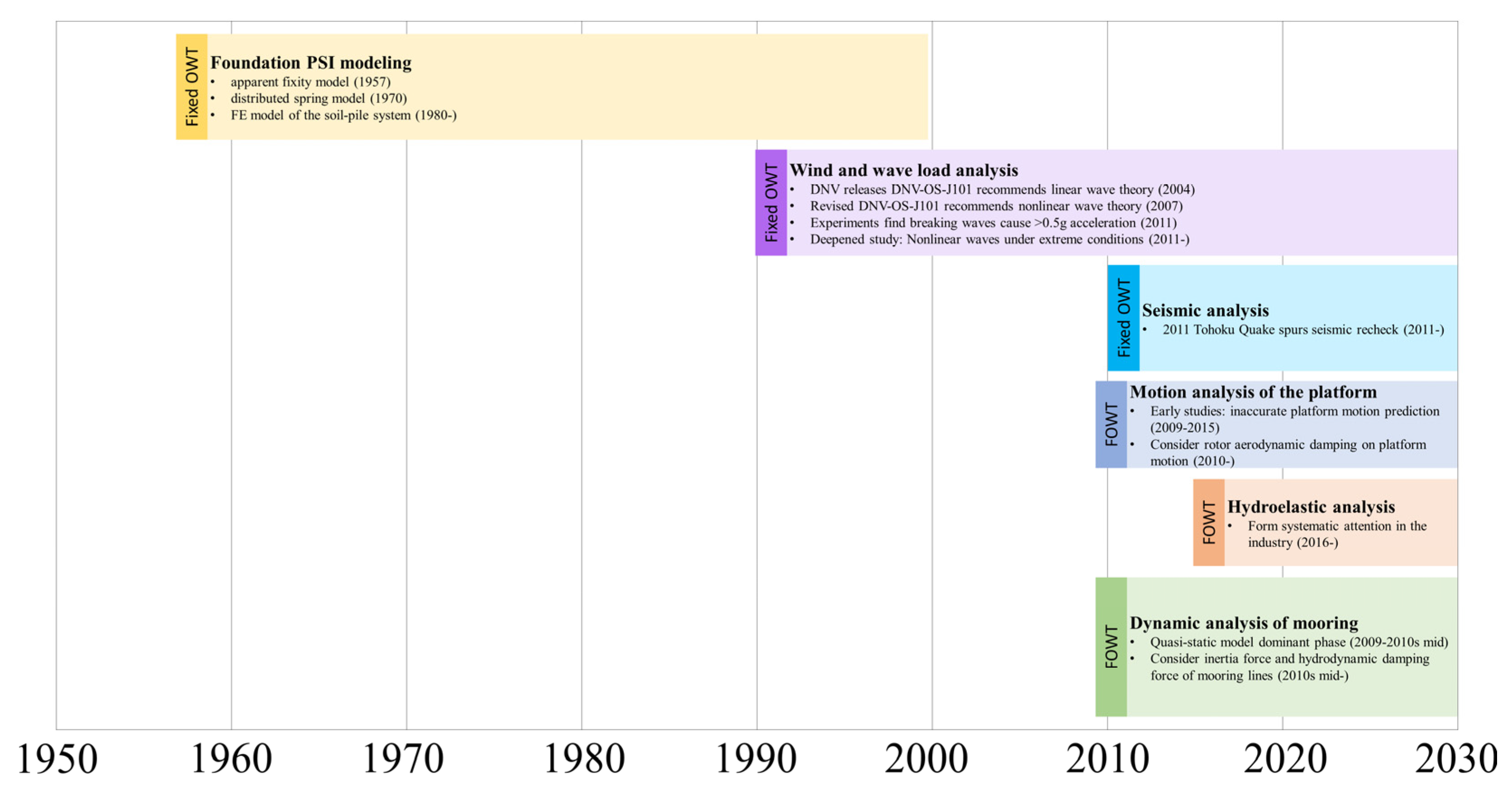
Figure 1. Timeline of the dynamics analysis development of OWT foundations.
Jmse 13 02016 g001
Figure 2. Structural foundation types of existing mainstream OWTs: (a) Gravity-based; (b) bucket; (c) monopile; (d) tripod; (e) jacket; (f) barge; (g) semi-submersible; (h) tension leg platform (TLP); and (i) spar.
Jmse 13 02016 g002
Figure 3. Floating wind–wave generation platform [19].
Jmse 13 02016 g003
Figure 4. Schematic diagram of FOWT-SFFC [24].
Jmse 13 02016 g004
Figure 5. Common mooring types: (a) Catenary; (b) umbrella-type tension; and (c) vertical tension leg [26].
Jmse 13 02016 g005
Figure 6. Schematic diagram of PSI [32].
Jmse 13 02016 g006
Figure 7. Foundation models: (a) apparent fixity model; (b) distributed spring model; and (c) FE model of the soil–pile system [37].
Jmse 13 02016 g007
Figure 8. Breaking wave-slamming loads onto the foundation of OWTs [55].
Jmse 13 02016 g008
Figure 9. Finite element analysis framework of OWTs under seismic loads [64].
Jmse 13 02016 g009
Figure 10. The 6-DOF motion of the FOWT foundation.
Jmse 13 02016 g010
Figure 11. Historical statistical values of dynamic response time under various conditions.
Jmse 13 02016 g011
Figure 12. Conceptual diagram of floating multi-unit platforms.
Jmse 13 02016 g012
Figure 13. Hydroelastic model developed by Li [89].
Jmse 13 02016 g013
Figure 14. Different layouts of mooring lines; (a) different quantities of lines; (b) different mooring pipes; (c) different line lengths; (d) different anchoring positions [97].
Jmse 13 02016 g014
Figure 15. Integrated research roadmap for OWT foundation dynamics.
Jmse 13 02016 g015
Table 1. Typical offshore wind power projects with different foundation types and their key parameters.
Type of Foundation Typical ProjectsWater DepthPer-Unit
Capacity (MW)
Key Application Features
MonopileThanet Offshore Wind Power Field (2010) [5]20–25 m3First commercially operating offshore wind power field in the UK
JacketBeatrice Offshore Wind Power Field (2006) [6]56 m7Applied in a medium-deep water scenario
Semi-submersible“The Three Gorges Leader” FOWT (2021) [7]-5.5Typhoon-resistant; independently developed by China
SparHywind Scotland Wind Power Field [7] (2017)95–120 m6First commercially operating deep-sea offshore wind power field worldwide
Table 2. The installation costs of monopile and jacket foundations in offshore wind farms [10].
Type of
Foundation
Cost of Quay-Side Lifts (EUR)Cost of
Transportation (EUR)
Cost of Substructure
Installation (EUR)
Cost of Stationed Personnel (EUR)Total Cost (EUR)
Monopile65 k47 k784 k63 k959 k
Jacket65 k47 k1176 k84 k1372 k
Table 3. Key performance and adaptability traits of fixed OWT foundations.
Type of Foundation Working PrincipleFoundation Soil RequirementsAdvantagesDisadvantages
Gravity-basedRelies on self-weight and internal loading weight to balance upsetting moments and sliding force.Wide soil adaptability.Strong resistance to windstorms and high waves.1. Heavy structure, difficult to transport and install.
2. High material consumption, high initial cost.
MonopileA single large-diameter steel pile is driven into the seabed.Unsuitable for soft soil or hard rock, and highly sensitive to seabed scouring.1. Simple structure, easy to design and manufacture.
2. Low cost for shallow water (≤30 m).
1. Not for deep water.
2. Prone to bending under horizontal loads.
3. Needs anti-scouring measures.
TripodDraws on offshore oil/gas experience, and tripod structure distributes loads to three legs.Requires hard/firm seabeds.1. High rigidity and strength, and good resistance to horizontal loads.
2. Good anti-scouring performance.
1. Strict soil requirements.
2. Complex on-site assembly.
JacketSteel truss structure fixed to seabed via piles.Wide soil adaptability.1. High bearing capacity.
2. Mature construction, and less affected by marine loads.
1. Complex structure, and difficult to design and manufacture.
2. High installation cost.
BucketNegative-pressure bucket: pump out internal air/water to suck it into seabed.Soft soil may have internal liquefaction.1. Suitable for inshore/offshore areas.
2. Short construction time.
1. Sensitive to seepage.
2. Risk of soil plug/liquefaction, leading to tilting.
Table 4. Key performance and adaptability traits of FOWT foundations.
Type of Foundation Working PrincipleWater DepthAdvantagesDisadvantages
Semi-submersibleDistributed buoy structures create large water plane changes.40–500 mMinimal cost growth with deeper water [10], retains deep-sea economic benefits.1. Large water plane area, easily affected by wave loads.
2. High sensitivity to second-order low-frequency wave forces [12].
bargeIncreases damping pool to reduce structural lateral displacement [13].40–500 m1. Relatively simple structure.
2. Low unit weight and cost.
1. Large water plane area, easily affected by wave loads.
2. High sensitivity to second-order low-frequency wave forces [12].
TLPGenerates stronger buoyancy than a dead load of wind turbines to balance off the tension of lines.30–500 mLower LCOE than other common floating foundations in shallow waters.1. High sensitivity to second-order high-frequency wave forces.
2. Structure cost surges with increasing water depth.
SparStability supported by ballast center of gravity.75–500 m1. Suitable for large-scale FOWTs.
2. Economic benefits when water depth reaches 400–500 m.
3. Small water plane area reduces platform motion [14].
High sensitivity to marine eddies.
Table 5. Initial cost for floating offshore wind turbines with different foundation types [17].
Type of FoundationPlatform (EUR/kW)Mooring Line (EUR/kW)Total Cost (EUR/kW)
Semi-submersible1.27 k0.76 k644 k
Barge0.87 k0.77 k768 k
Spar0.65 k0.67 k786 k
Table 6. Comparison of three types of foundation models.
Type of Foundation ModelsApplication RangeAdvantagesDisadvantages
Apparent fixity modelSmall subgrade stiffness and ignoring displacement of the tower topThe model is simple and has high sensitivity to pile diameter and pile thicknessUnderestimates subgrade stiffness, and ignores influences of soil mass conditions on displacement response as well as changes in soil mass constraint caused by pile diameter
Distributed spring modelHigh subgrade stiffnessPredict subgrade stiffness accuratelyIgnores continuity effect of soil bed [38] as well as effects of soil mass conditions on displacement responses
FE model of the soil–pile systemHigh subgrade stiffnessMore sensitive to soil compaction and buried depth of pilesHeavy computation loads
Disclaimer/Publisher’s Note: The statements, opinions and data contained in all publications are solely those of the individual author(s) and contributor(s) and not of MDPI and/or the editor(s). MDPI and/or the editor(s) disclaim responsibility for any injury to people or property resulting from any ideas, methods, instructions or products referred to in the content.