Article

Experimental Study on CO2 Sequestration in Marine Environments During Hydrate Recovery by Depressurization Combined with Replacement

1
Key Laboratory of In-Situ Property-Improving Mining of Ministry of Education, Taiyuan University of Technology, Taiyuan 030024, China
2
School of Safety and Emergency Management Engineering, Taiyuan University of Science and Technology, Taiyuan 030024, China
*
Author to whom correspondence should be addressed.
J. Mar. Sci. Eng. 2025, 13(10), 1977; https://doi.org/10.3390/jmse13101977
Submission received: 19 September 2025 / Revised: 5 October 2025 / Accepted: 13 October 2025 / Published: 16 October 2025

Abstract

To protect the environment, sequestering CO2 during the extraction of natural gas hydrates is a highly promising carbon-neutral technology. We investigated methane extraction and CO2 storage by a combined depressurization and CO2-injection method. In the seabed environment, the hydrate-forming period is ~300 min. When injecting liquid carbon dioxide into the reservoir, a replacement rate of ~11.1% is insufficient to meet the requirements for extracting methane and sealing carbon dioxide. Increasing the depressurization pressure can increase gas production. However, an excessively large depressurization pressure will cause the permeability damage rate (PDR) to reach 76.40%, which is not conducive to the continuous progress of the project. Increasing the depressurization pressure (7 MPa) and extending the depressurization pressure time (3 h) can effectively increase the final hydrate saturation (HS) and protect the reservoir permeability. This means higher reservoir stability and more sealed carbon dioxide. A new method has been proposed, namely, the coupling of depressurization and CO2 injection. This method actually extends the depressurization time, resulting in an average reservoir permeability of 1.72 millidarcies, thereby achieving a carbon dioxide storage rate of 27.7%. At the same time, it avoids the repeated implementation of pressure reduction and CO2 injection, reducing the complexity of the project.

1. Introduction

With the issue of global warming becoming increasingly urgent, research institutions around the world are stepping up efforts to explore low-carbon-emission technologies [1]. Currently, many scholars are developing carbon-capture and -storage (CCS) technologies to reduce CO2 emissions into the atmosphere and alleviate the problem of global warming [2,3,4,5,6,7]. Natural gas hydrates (NGHs), with their large reserves, wide distribution, and low pollution, are regarded as a potential future energy source [8]. NGH are cage-like compounds similar to ice, with methane trapped within the cages formed by water molecules [9,10]. Currently, many scholars are dedicated to researching a replacement method for extracting natural gas hydrates [11,12]. This method involves injecting carbon dioxide into the natural gas hydrate reservoir. During this process, due to the better thermodynamic stability of carbon dioxide hydrates [13], carbon dioxide can replace the methane in the water cages, thereby achieving both the extraction of hydrate resources and the storage of CO2 simultaneously [14]. This method not only ensures the stability of the strata [15], but also achieves the dual goals of clean energy production and carbon storage simultaneously. Therefore, it is regarded as a highly promising carbon-storage technology.
The theoretical efficiency of carbon dioxide replacement can reach 75%. The replacement method has fatal flaws [16]. The CO2–CH4 replacement reaction can only occur on the surface of the hydrate, because it is difficult to penetrate CO2 into the interior of the hydrate [17]. Therefore, the replacement efficiency of carbon dioxide and methane is lower than the theoretical value. As shown in Figure 1, past studies have confirmed that hydrate replacement can take place in both Zone A and Zone B. The temperature and pressure in the Shenhu area of the South China Sea are shown in Zone C, but studies on hydrate replacement in this area are rare. Usually, other methods are needed to break the structure of the hydrate in order to allow the CO2–CH4 replacement reaction to continue to proceed towards the interior of the hydrate [18]. In recent years, research has found that the depressurization combined replacement method is a promising method for extracting natural gas hydrates and sequestering CO2 [19]. This method decomposes and destroys the hydrate cage by reducing pressure, thereby improving the replacement efficiency [20]. Due to the simplicity of the depressurization method and its low cost [21], it has attracted the attention of many scholars [22,23].
The current combined depressurization and replacement method mainly consists of two technical routes. One route involves injecting CO2 into the hydrate reservoir for replacement. When the replacement efficiency decreases, the pore pressure of the reservoir is reduced, causing partial dissociation of methane hydrate (MH). Then, CO2 is injected back into the hydrate reservoir for replacement. This process continues until all the MHs in the reservoir have been extracted and the CO2 hydrates have been synthesized [24]. The other route is to first extract the MHs from the reservoir using the depressurization method, and then inject CO2 into the depleted hydrate layer to achieve the sealing of CO2 in the form of hydrates [19].
The research on the second technical route mainly adopts indoor experiments. Niu et al. studied small-scale reactors and pilot-scale reactors to investigate the effects of depressurization, CO2/N2 ratios and well types on carbon sequestration [19]. Adding nitrogen to CO2 will enhance the replacement efficiency [25]. Because nitrogen will occupy the small cages that CO2 cannot, this will increase the theoretical replacement efficiency from 75% to 100%. At the same time, the diffusion of nitrogen molecules into the hydrate cage will disrupt the thermodynamic stability of the original methane hydrates, thereby promoting the release of methane molecules. Yao et al. studied the initial saturation of hydrates [26], depressurization [27], liquid carbon dioxide [28], and the effects of different experimental scales [29] on carbon sequestration using the depressurization combined replacement method. Currently, the research on this technical route is all conducted based on the temperature and pressure of hydrate reservoirs in the South China Sea region. How to avoid the formation of hydrates in the reservoir near the injection well, causing reservoir blockage, is one of the problems that this method needs to solve [30]. The research on the first technical route mainly adopts indoor experiments and numerical simulation. Sun et al. confirmed the feasibility of the first technical route through indoor experiments [24]. Jiang et al. explored the feasibility of the first technical route at the engineering scale using numerical simulation methods [31]. The experimental temperatures of this technical route are mostly within 283.15 K, while the temperature of the hydrate layer on the seabed in the South China Sea region usually ranges from 282.15 K to 290.15 K [32]. Within this temperature range, CO2 hydrates cannot be formed alone, and a mixture of CO2–CH4 or CO2–CH4–N2 is required for formation. This paper conducts research under the P-T conditions of the seabed in the South China Sea using the depressurization combined with replacement method. Based on this research, a new method combining depressurization and replacement, namely, injecting CO2 during the decomposition of hydrates, is proposed. In this method, the injected carbon dioxide does not form hydrates initially. As the hydrates decompose, when the proportion of liquid CO2 and methane reaches the equilibrium condition of the mixed hydrate, the mixed hydrate begins to form.
Therefore, this study employed a three-axis testing system to simulate the actual conditions of temperature, pore pressure, and in situ stress in the South China Sea reservoirs. Through the application of the first technical route and the new method of depressurization coupled with CO2 injection for extracting CH4 and CO2 storage, the influence of depressurization pressure and depressurization time on the CO2 storage in the first technical route was investigated. The evolution characteristics of P-T, gas production, permeability, and mixed hydrate (Mix-H) formation were investigated, the effects of depressurization pressure and depressurization time on methane gas production were evaluated, and CO2 storage and reservoir permeability were examined. At the same time, the effects and mechanisms of the first technical route and the new method of depressurization coupled with replacement on methane gas production, CO2 storage, and reservoir permeability were compared and analyzed. These findings provide suggestions for efficient extraction of CH4 and CO2 storage in gas hydrate reservoirs.

2. Materials and Methods

2.1. Experimental Materials and Apparatus

The samples used in this experiment were artificially prepared in the laboratory. To ensure that the samples could represent the actual samples from the seabed of the South China Sea, the mineral composition and particle size composition of the samples were made as consistent as possible with those of the samples from the South China Sea. According to the literature, the clay content in the methane hydrate sediments of the Dongsha area mainly range from 20% to 40%, and the clay components are mainly illite and montmorillonite [33,34]. The experimental samples were composed of silt (80.00%) and montmorillonite (20.00%), and the particle size distribution curve is shown in Figure 2 (Minghai Environmental Technology Co., Ltd.). The experimental water used was distilled water, to preventions in the water from affecting the formation and replacement of hydrates. CH4 and CO2 used in the experiment were prepared in the laboratory and had a purity of 99.99% (Taiyuan Anxu Hongyun Technology Development Co., Ltd.).
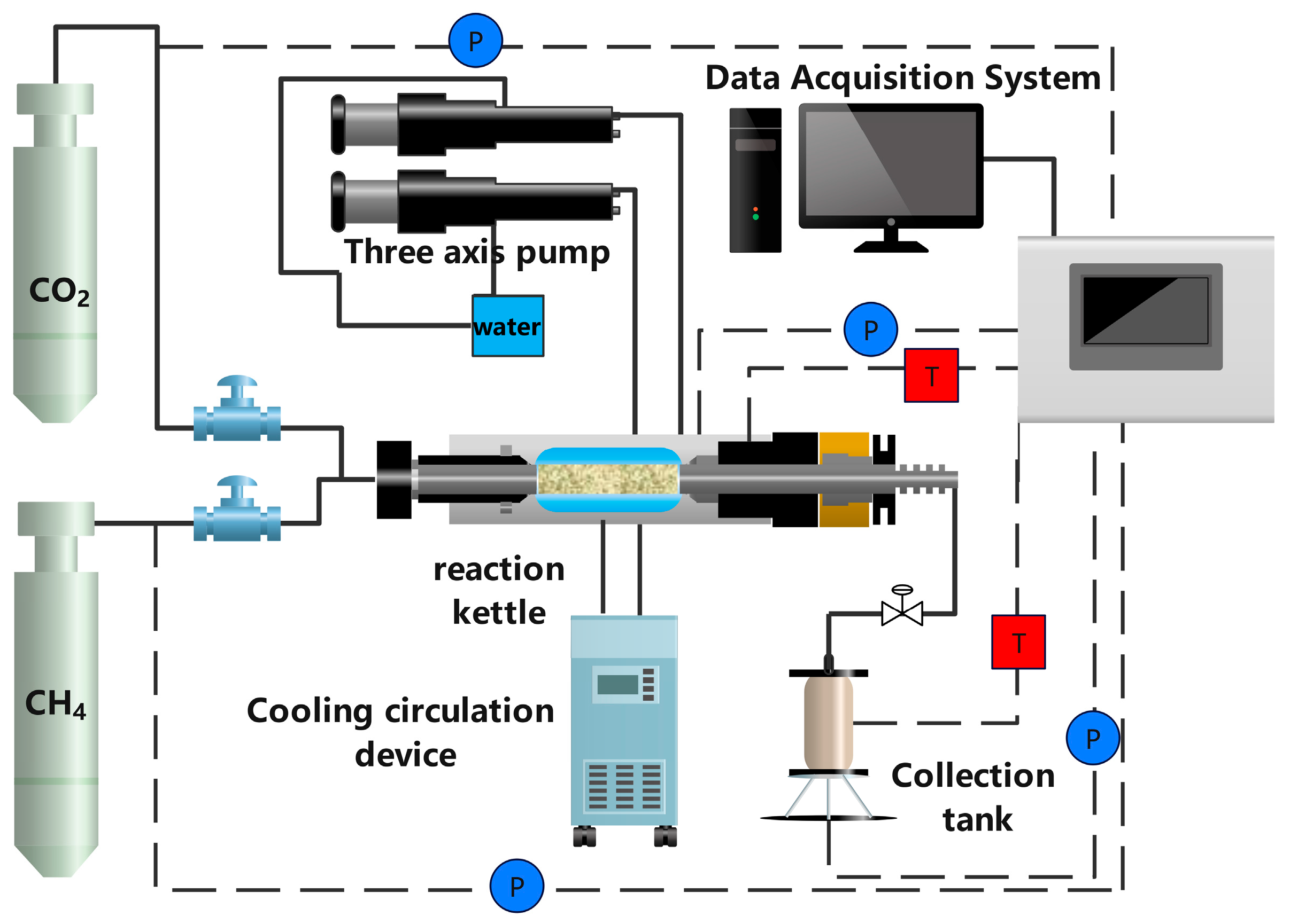
Figure 3 shows the depressurization and replacement-test system used in the experimental study. This system can simulate seabed pore pressure (0.00–20.00 MPa), in situ stress (0.00–30.00 MPa), and ground temperature (253.15–373.15 K). More details regarding the materials and apparatus can be found in our previous paper [35].

2.2. Experimental Procedures

2.2.1. Specimen Preparation and MH Formation

First, prepare the experimental samples. Dry the silt and montmorillonite (300.0 g) and mix them evenly with deionized water (accounting for 70.00%). Then, divide the samples into 10 portions and fill them into the jacket one by one. Each filling process should be accompanied by the same numbers of tapping and compaction. Clean the triaxial reaction chamber thoroughly and dry it. Insert the sample-filled jacket into the triaxial reaction chamber. Set the water bath tank at T = 291.15 K. Vacuum the reaction chamber and maintain it for 20 min. Then, inject methane to P = 14.00 MPa and stabilize for 2 h (as marked by transition A→B in Figure 4). Then, set T = 285.15 K and induce the formation of MH (as marked by transition B→C in Figure 4). When the pressure in the reaction chamber is less than 13.00 MPa, continue to inject methane to P = 14.00 MPa. When the MH saturation reaches about 28%, stop the formation. Inject deionized water to displace the excess methane in the reaction chamber until the sample is in a saturated water state. This process takes approximately 48 h.
The MH saturation can be calculated using Equation (1):
S Hi = m H ρ H V = n H M H ρ H V
where m H is the MH quality, MH is the MH molar mass, ρ H (0.91 g/cm3) is the MH density, V is the pore volume (mL), and n H is the consumption of CH4.
When testing the permeability of the reservoir, liquid CO2 is used for the test. In the reservoir, only liquid CO2 flows, so the permeability (K0) is calculated using Equation (2):
K 0   = μ Q 0 L / π r 2 ( P 1     P 2 )
where r is the sample radius (cm), Q0 is the liquid CO2 flow rate (mL/s), μ is the liquid CO2 viscosity (Pa·s), P1P2 is the pressure difference between the inlet and outlet of the reactor (Pa), and L is the sample length (cm). One Darcy = 0.987 × 10⁻¹² m2.
Permeability damage rate (PDR) can be calculated using Equation (3):
D KD   =   K i     K 0 K 0 × 100 %
where DKD is the PDR after depressurization, Ki is the permeability after depressurization, and K0 is the permeability before depressurization.

2.2.2. MH Replacement

After the formation of MH is completed, inject liquid CO2 at P = 13.00 MPa until no water is discharged at the outlet. Then, use liquid CO2 to test the permeability of the samples. After the permeability test is completed, maintain P = 13.00 MPa to allow the MH to undergo a 48 h replacement (from point D to E in Figure 4). Collect the gas from the entrance and exit three times every two hours, each time collecting 5 mL. The proportion of methane in six gases were tested by gas chromatography, and then the average value was calculated. This can make the collected gas more representative, thereby reducing the error caused by chance. The equipment used was a specialized gas analyzer, custom-made by Thermo Fisher (Shanghai, China) for detecting hydrate gases. The RSDs were found to be less than 3.0%. An internal standard calibration method was employed to ensure quantification accuracy and precision. After the replacement is completed, use liquid CO2 to test the permeability of the samples again.
The CH4/CO2 hydrate saturation (HS) is calculated using the compressible liquid state equation [28]. The replacement rate ( η CH 4 / CO 2 ) can be calculated by Equation (4):
η CH 4 / CO 2 = n CO 2 n CH 4
where n CO 2 is the consumption of CO2 (mol) and n CH 4 is the number of moles of initial MH (mol).

2.2.3. Depressurization

In cases 1–5, after the hydrate replacement was completed, the back pressure valve of the reaction vessel was adjusted to P = 7.00 MPa (the design pressures were 7.00 MPa, 6.00 MPa, and 5.00 MPa), while keeping the axial pressure and peripheral pressure of the reaction vessel constant (from point D to E in Figure 4). When the depressurization pressure (5 MPa and 6 MPa) is lower than the equilibrium pressure of this phase (6.61 MPa), the mixed hydrate will decompose rapidly. The phase equilibrium pressure of the mixed hydrate (with a methane content of 10%) is 6.36 MPa. When the pressure drop is 7 MPa, only a small portion of the mixed hydrates (with a methane content of less than 10%) will decompose. The gas discharged during the dissociation was collected in a collection tank and the gas composition was tested every two hours. Every two hours, the gas in the reaction vessel was collected (30.0 mL) and the gas composition was analyzed. The dissociation was stopped when it reached the set time (design time was 1 h, 2 h, and 3 h), and the sample permeability was tested using a CH4/CO2 mixture (the mixture was prepared according to the proportion of the discharged gas beforehand). In case 6, after the hydrate replacement was completed, the back pressure valve of the reaction vessel was adjusted to P = 7.00 MPa (the design pressures were 7.00 MPa, 6.00 MPa, and 5.00 MPa), and liquid CO2 was injected at a pressure of P = 7.00 MPa (point D→F in Figure 4). The replacement reaction lasted for 96 h. The permeability test and gas composition tests were the same as in cases 1–5.

2.2.4. Secondary MH Replacement

In cases 1–5, after the hydrate dissociation is completed, the pre-cooled liquid CO2 is re-injected to restore the reactor pressure to P = 13.00 MPa (point E→D in Figure 4). The replacement is maintained for 48 h, and gas is collected in the reactor every 2 h. After the second replacement is completed, the sample permeability is tested using a CH4/CO2 mixture (the mixture is prepared in advance according to the proportion of the discharged gas). Then, steps 2.2.3 and 2.2.4 are repeated to perform the second depressurization and the third hydrate replacement.
MH retention rate (RET) and hydrate restoration ratio (RES) can be expressed as the following:
RET = S CH 4 , Mix-H S CH 4 × 100 %
RES = S Mix-H S CH 4 × 100 %
where S CH 4 ,   Mix-H is the MH saturation after Mix-H formation (%), S Mix-H is the Mix-H saturation after Mix-H formation (%), and S CH 4 is the initial MH saturation (%).
The hydrate molar quantity change ratio (MHC) is as follows:
MHC = n CH 4 , Mix-H   -   n CH 4 n CH 4 × 100 %
where n CH 4 ,   Mix-H is the number of moles of MH after Mix-H formation (%).

3. Results

3.1. Hydrate Formation and Replacement

Table 1 summarizes the conditions and results of the hydrate formation experiments in cases 1–6. It can be seen that the conditions for hydrate formation in cases 1–6 are consistent, and the saturation of the synthesized hydrates for all cases is around 30.00%. The same HS provides the same initial conditions for the subsequent six sets of experiments, thus ensuring the accuracy of the experiments. Figure 5 shows the changes in P and T over time during the formation of hydrates in case 1. When liquid CO2 is injected into the mudstone-sand sample and the sample temperature is reduced, it is observed that the gas pressure decreases rapidly, indicating that MH begins to synthesize in the sample. After approximately 300 min, the rate of gas depressurization slows down. To increase the hydrate formation speed, when the pressure drops to 12.93 MPa, liquid CO2 is injected again to restore the pressure to 14.00 MPa. It is observed that the rate of gas depressurization is still slow, indicating that under the triaxial condition, after a brief period of rapid formation, the hydrate formation speed is relatively slow for most of the time.
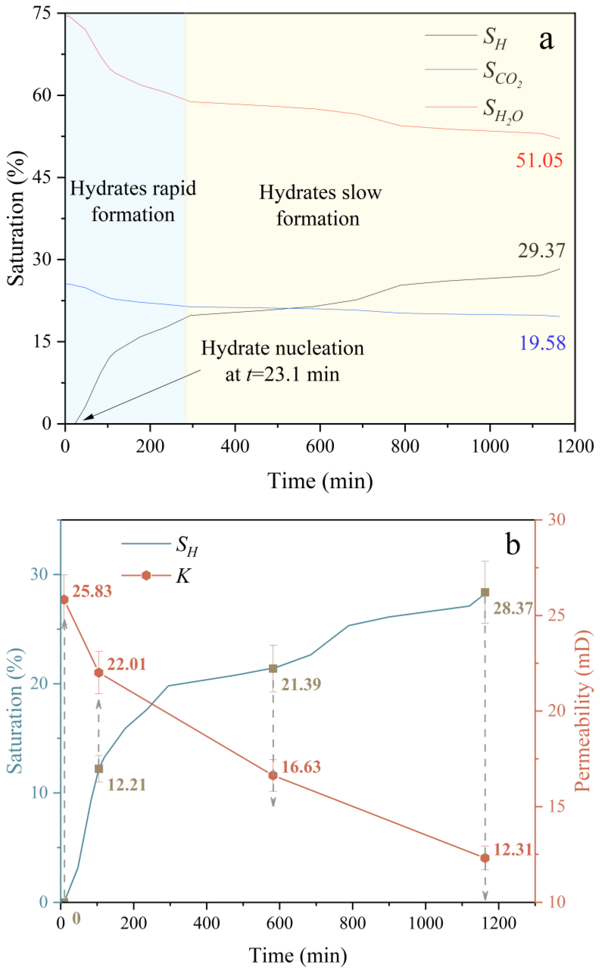
Figure 6a shows the proportions of hydrate, liquid CO2, and water in the samples during the hydrate formation process. After 23.1 min of liquid CO2 injection, the hydrate began to rapidly synthesize. The rapid formation period lasted for 294.8 min, after which the HS reached 19.80%. At this point, the hydrate formation entered a slow formation period. Even if the formation pressure was increased later, the hydrate formation speed did not significantly increase. After approximately 868.4 min of slow formation, the HS reached 29.37%. This indicates that the hydrate formation speed is relatively slow under the triaxial condition, and obtaining high saturation hydrate requires increasing the reaction time.
Figure 6b shows the relationship between the HS and permeability during the hydrate formation process. The permeability of the samples were tested under the conditions of HS of 0.00%, 12.21%, 21.39%, and 29.37%. The obtained permeability values were 25.83 mD, 22.01 mD, 16.63 mD, and 12.31 mD, respectively. It was observed that under the water-rich condition, the HS of the sample increased to 29.37%, while the reservoir permeability decreased from 25.83 mD to 12.31 mD. This suggests that the MH saturation in the sample was too high, which was not conducive to the injection of liquid CO2.
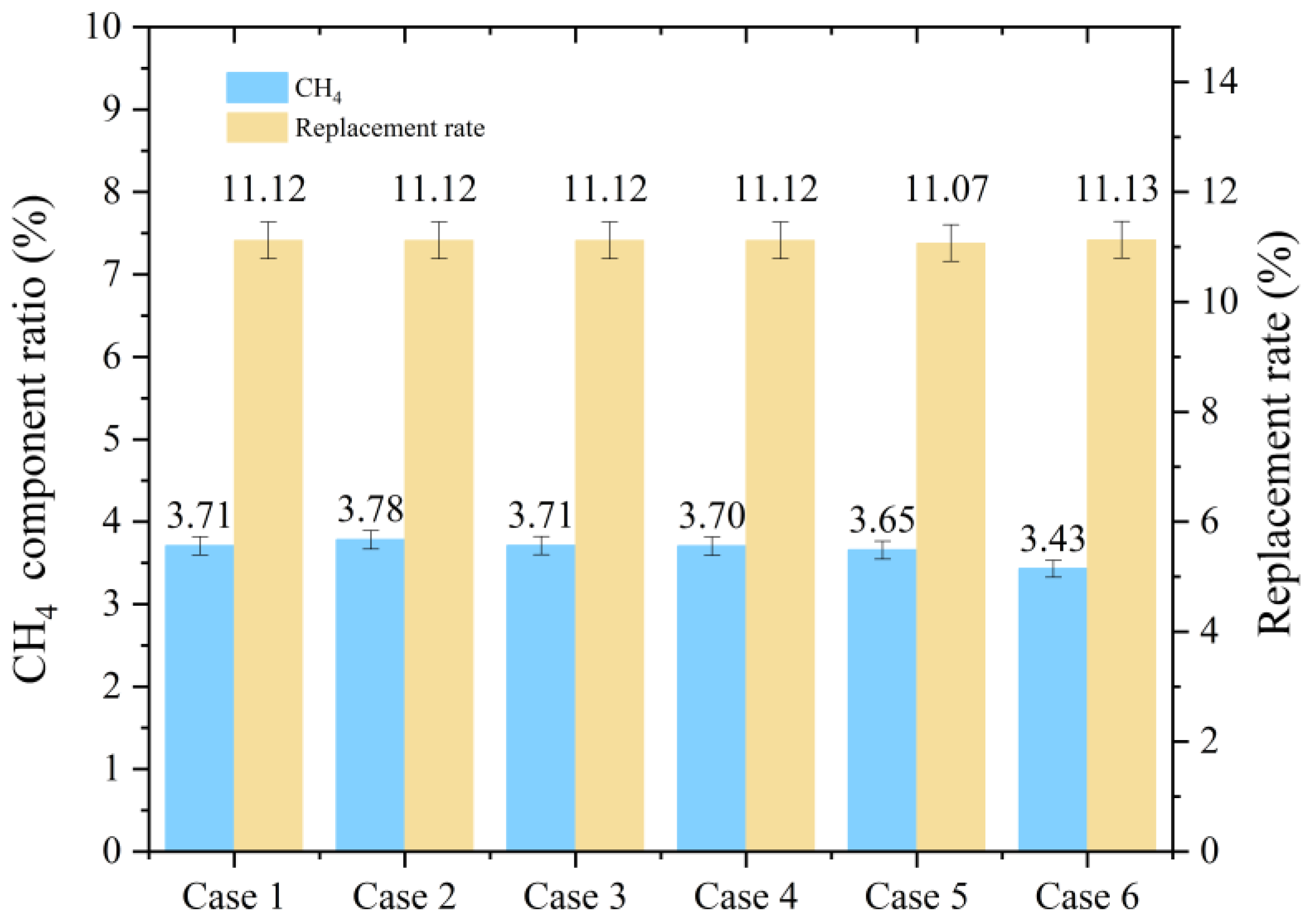
After the formation of MH was completed, liquid CO2 was injected for a 48 h replacement. Figure 7 shows the proportion of methane and the replacement rate in the CH4/CO2 system in the six cases. It can be observed that since the initial MH saturation was the same, the proportion of methane and the replacement rate were relatively close. In the six cases, the reaction temperatures were all 285.15 K, and the injection of liquid CO2 had all undergone replacement, but the 48 h replacement rate was only 11.07–11.13%. You et al. conducted a study under stress-free conditions, with a temperature of 285.15 K and pressures ranging from 177.71 to 20.11 MPa [36]. They found that the replacement rate could reach 30.55%. However, under triaxial experimental conditions, the replacement rate was only approximately 11%, which requires attention. This indicates that the replacement efficiency is low in the underwater environment, and other methods must be adopted to further increase the replacement rate. Moreover, since the proportion of methane is relatively low, the CH4/CO2 Mix-H cannot be synthesized, and other methods must be adopted to further increase the proportion of methane to achieve CO2-hydrate sequestration.

3.2. Depressurization

Figure 8a shows the curves of cumulative gas production during the two depressurization processes under different depressurization pressures (7.00 MPa, 6.00 MPa, 5.00 MPa). It can be observed that the gas production rates are relatively fast under the depressurization pressures of 7.00 MPa, 6.00 MPa, and 5.00 MPa. In the initial stage of gas production, the gas produced mainly consists of the extraction of CH4 and CO2 from the sample and the dissociation of hydrates. Due to the duration of depressurization being only 1 h, the dissociation rate of hydrates is still in the rapid dissociation stage. Therefore, regardless of whether it is the first depressurization or the second one, the gas production is in the rapid dissociation stage. All the second depressurization gas production curves are observed to be lower than the primary depressurization gas production curves. This is because the dissociation rate of hydrates decreases as the HS decreases, resulting in a decrease in the gas production rate. Moreover, when the depressurization pressure is reduced from 7.00 MPa to 5.00 MPa, the driving force for hydrate dissociation increases. The gas production from the first depressurization increases from 0.178 mol to 0.332 mol, and the gas production from the second depressurization increases from 0.132 mol to 0.262 mol. This indicates that reducing the depressurization pressure can significantly increase the gas production.
Figure 8b shows the curves of cumulative gas production during the two depressurization processes under different depressurization times (1 h, 2 h, 3 h). It can be observed that the gas production speed during the first depressurization is also relatively fast under the conditions of 1 h, 2 h, and 3 h depressurization times. This indicates that within a duration of 3 h for depressurization, the dissociation rate of hydrates is still in the rapid dissociation stage. The gas production speed during the second depressurization is also relatively fast under the conditions of 1 h and 2 h depressurization times. The gas production speed during the second depressurization under the 3 h depressurization time condition tends to slow down. This is because under the 3 h depressurization time condition, the gas production volume during the second depressurization has reached 0.408 mol, and most of the MH have decomposed and the dissociation of hydrates enters a slow stage. Moreover, in case 6, it can be found that when the depressurization time continues for 5 h, the production rate begins to enter the slow stage. This is the same reason as the slowdown of the gas production speed during the second depressurization in case 5. It can be observed that an increase in depressurization time can also significantly increase the gas production volume, but as the dissociation rate of hydrates slows down, the effect of increasing the depressurization time on gas production becomes worse.
Figure 9 shows the percentage of methane in the CH4/CO2 system before and after the first depressurization and before and after the second depressurization in cases 1–5. Observation revealed that before the first depressurization, the percentage of methane was relatively low, and the CH4/CO2 Mix-H could not be synthesized. After the first depressurization, the percentage of methane increased from 3.21–3.78% to 13.20–23.07%, and the formation conditions for all experimental groups of CH4/CO2 Mix-H had been achieved. This indicates that depressurization can effectively promote the formation of CH4/CO2 hydrates. When the depressurization pressure was reduced from 7.00 MPa to 5.00 MPa, the amount of hydrate dissociation increased, resulting in a 27.01% increase in the percentage of methane in the fluid. When the depressurization time was increased from 1 h to 3 h, the percentage of methane in the fluid also increased from 13.40% to 32.13%. Both the reduction in depressurization pressure and the extension of depressurization time can effectively increase the percentage of methane. The effect of extending the depressurization time is more significant. The second depressurization could also increase the percentage of methane to 20.27–34.88%. However, a higher percentage of methane means an increase in the percentage of methane in the hydrate, which will reduce the sequestration capacity of CO2 in the hydrate. Additionally, in case 6, it can be observed that the percentage of methane was relatively low after depressurization, because in this experimental case, the dissociation of MH and the formation of Mix-H were carried out simultaneously, and the methane content increased and then decreased as the reaction proceeded. Therefore, the percentage of methane in the gas after depressurization cannot reflect the percentage of methane throughout the entire reaction process. Section 3.3 will provide further analysis.
Figure 10 shows the changes in permeability using a log scale before and after the first depressurization and before and after the second depressurization. Before the first depressurization, the permeability of samples 1–6 was 7.39–8.27 mD. After depressurization, the permeability decreased to 0.94–2.57 mD. During depressurization, as the pore pressure of the samples decreased, the effective stress increased, which led to a significant decrease in the permeability of the hydrate samples before and after depressurization. Before the second depressurization, the permeability of the samples was 0.93–1.51 mD, and after depressurization, the permeability decreased to 0.92–1.51 mD. The reduction in permeability of the samples during the second depressurization was significantly smaller. This is because the plastic deformation of the samples caused by the increase in effective stress mainly occurred during the first depressurization and could not be restored. The compression amount of the samples during the second depressurization was significantly reduced. Li et al. have the same conclusion [37]. In addition, as the depressurization pressure increases (from 7 MPa to 5 MPa), the effective stress increases, and the permeability damage rate of the samples increases from 75.08% to 76.39%. With the extension of depressurization time (from 1 h to 3 h), the dissociation of hydrate increases, and the permeability damage of the samples decreases from 75.08% to 68.16%. In case 6, MH decomposed the most, and the permeability damage of the samples was the least.

3.3. Mix-H Formation

Figure 11a shows the evolution of pressure and the ratio of CH4/CO2 components during the formation process of the CH4/CO2 Mix-H in case study 1. Figure 11b presents the formation situation of the CH4/CO2 Mix-H in all cases after the second and third replacements. Due to the relatively slow formation rate of hydrates under the triaxial condition, in order to accelerate the reaction rate during the formation process of the CH4/CO2 Mix-H, the reaction pressure was kept constant in the experiment. It was observed that during the first replacement, some CH4 was displaced, so the proportion of methane increased from 0% to 3.70%. Due to the small proportion of methane, no CH4/CO2 Mix-H formation was observed during the first replacement. After 48 h of replacement, the first depressurization was carried out, and the proportion of methane increased to 13.06% after the depressurization. Then, liquid CO2 was injected to prepare for the second replacement. Due to the dilution of methane concentration by the injected liquid CO2, the proportion of methane decreased to 9.57%. From Figure 11b, it can be seen that a large amount of CH4/CO2 Mix-H was synthesized during the second replacement. To maintain the constant system pressure, CO2 was continuously added to the sample, and theoretically, the proportion of methane should have decreased. During the second replacement, the proportion of methane increased, indicating that water hydrate replacement occurred during this process. Due to the simultaneous occurrence of water hydrate replacement and Mix-H formation during the second replacement, it is difficult to quantitatively calculate. Further improvements are needed to further analyze this process. After the second depressurization, the proportion of methane increased to 20.26%. In the third replacement process, the proportion of methane slightly decreased to 11.14%, indicating that the formation of CH4/CO2 Mix-H played a major role in the third replacement.
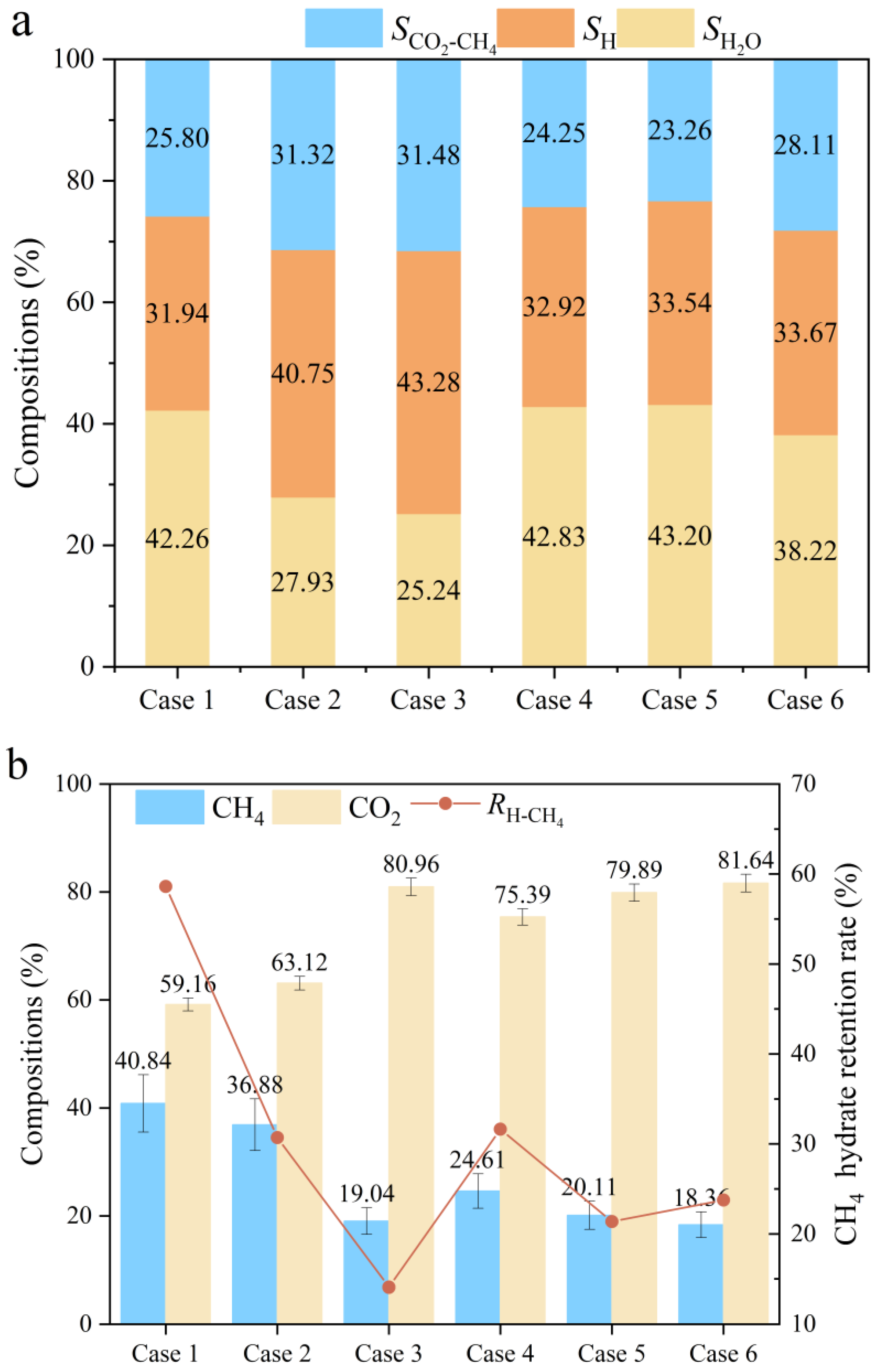
Figure 12a presents the proportions of liquid CO2–CH4, water, and hydrates in the sample pores in all cases. The HS in cases 2 and 3 are significantly lower than that in other cases. This is because the depressurization pressure in case 2 is 6.00 MPa, and in case 3 it is 5.00 MPa. The minimum phase equilibrium pressure of the Mix-H is 6.35 MPa [38]. In this situation, depressurization drives the dissociation of the Mix-H and MH. In other cases, the depressurization pressure is 7.00 MPa. Lowering the pressure does not cause the dissociation of the Mix-H, so the final HS is relatively high. This indicates that excessive depressurization is not conducive to the sealing of Mix-H. Extending the depressurization time, the final HS does not change much. Moreover, in case 6, although the formation pressure of the Mix-H is 7.00 MPa (lower than 13.00 MPa in other cases), the final HS is relatively close to that of cases 1 and 5. This indicates that depressurization coupled with CO2 injection can also achieve a considerable amount of hydrate sequestration.
Figure 12b shows the proportions of each component in the Mix-H and the retention rate of MH in all cases. A decrease in the depressurization pressure (from 7.00 MPa to 5.00 MPa) and an extension of the depressurization time (from 1 h to 3 h) will promote the dissociation of MH, resulting in a decrease in the proportion of methane in the Mix-H and the retention rate of MH. This seems to indicate that the less MHs are retained, the higher the proportion of CO2 in the Mix-H, which is more conducive to the sealing of hydrates. In case 6, the MHs were retained the least, and the proportion of CO2 in the Mix-H was the highest.
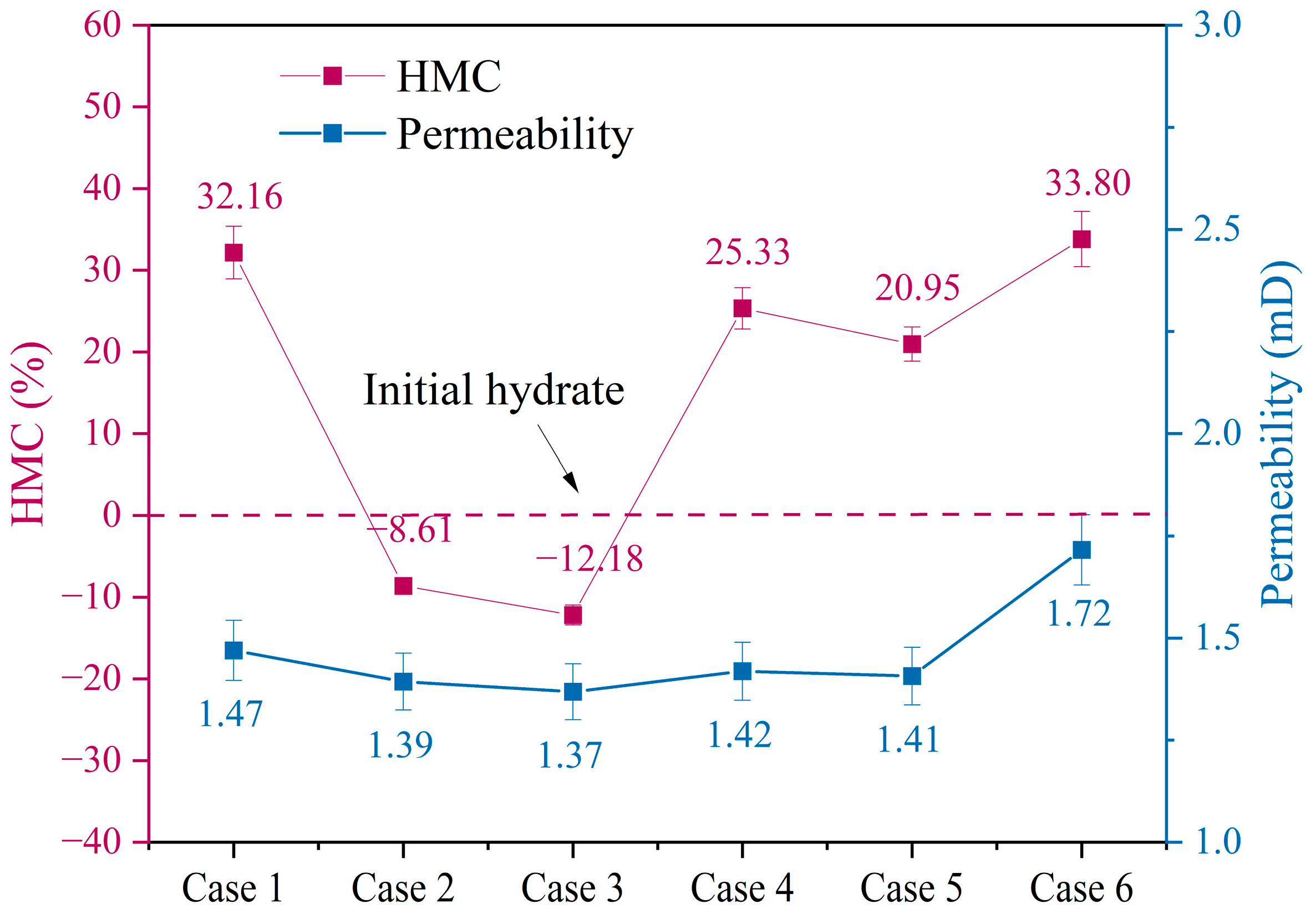
Figure 13 shows the relationship between the average permeability of the samples and MHC in all cases. The average permeability of the samples is obtained by averaging the permeability values at the end of each stage. It was observed that the greater the average permeability of the samples, the greater the increase in the MHC. In cases 2 and 3, the average permeability of the samples was the lowest (1.39 mD and 1.37 mD, respectively), and the MHC decreased compared to the initial MHC. This was due to the low permeability hindering the diffusion of liquid CO2–CH4, thereby inhibiting the formation of Mix-H. In case 6, MH dissociation was the most significant, the average permeability was the highest, and the change in the MHC was the greatest.

4. Discussion

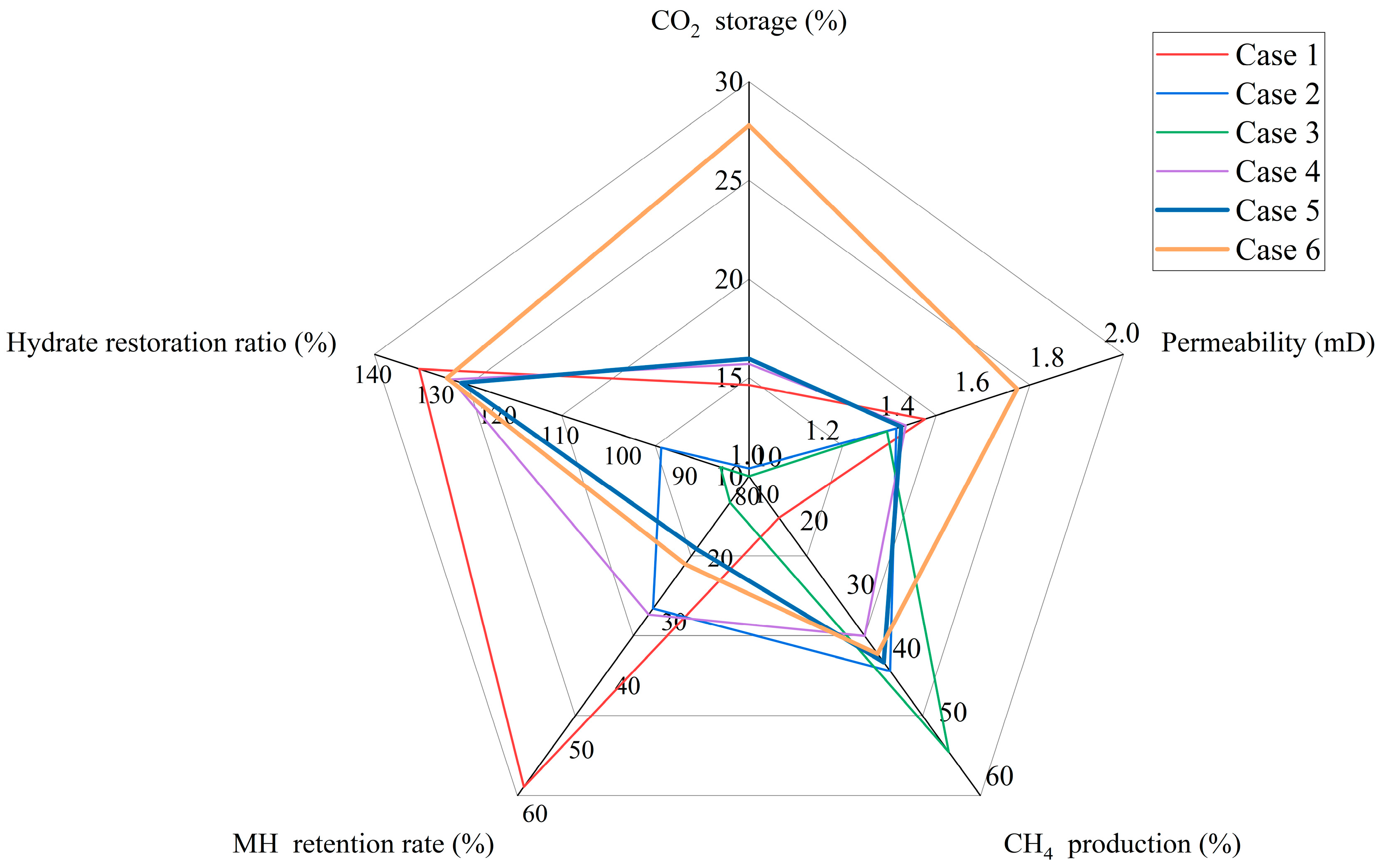
Figure 14 presents the assessment results of carbon dioxide sequestration and methane extraction under various depressurization levels and durations. Among cases 1–5, case 5 received the best evaluation because case 5 adopted a smaller depressurization level and a longer duration of depressurization. The smaller depressurization level prevented permeability damage and dissociation of carbon dioxide hydrates. The longer duration promoted the dissociation of MH and the increase in permeability. Compared with case 5, case 6 received a better evaluation. Due to the lower formation pressure of Mix-H in case 6, the injection volume of carbon dioxide decreased and the sequestration rate of carbon dioxide (the percentage of injected carbon dioxide that turns into hydrates) increased. At the same time, more MH decomposed in case 6, which resulted in a higher average permeability of the samples.
Based on the experiments of this study, the use of depressurization coupled with CO2 injection for carbon sequestration in the marine environment has the following advantages: (1) Injecting liquid CO2 in the marine environment prevents the direct formation of CO2 hydrates, which is conducive to the diffusion of liquid CO2 in the reservoir. (2) Performing depressurization at specific times and locations can enable the CH4/CO2 ratio to reach the conditions for synthesizing CH4/CO2 Mix-H, thereby allowing the CH4/CO2 Mix-H to be synthesized first between the injection well and the production well, which avoids the formation of hydrates near the injection well and production well blocking the reservoir. (3) The depressurization coupled with CO2 injection method avoids multiple depressurizations and CO2 injections, thereby reducing the engineering complexity. However, there are also some challenges when using this method to extract hydrates: (1) There has always been a mixture of hydrate formation and hydrate existence in the reservoir, which seems to be more conducive to maintaining the stability of the reservoir and wellbore. (2) Hydrate formation is an exothermic process, which helps to slow down the decrease in reservoir temperature and thus slow down secondary hydrate formation. (3) Under field conditions, how to combine the timing of depressurization and the timing of CO2 injection is crucial. (4) When using this method near the production well, due to the low pore pressure, it is difficult for the mixture hydrate to be formed. When the mixture hydrate formation is completed in the middle of the reservoir, it is recommended to use the method proposed by Yao et al. [27,30], by injecting a specific proportion of CH4/CO2 mixture through the production well, so as to seal CO2 near the production well. All of these are key issues that require further in-depth research and solutions.

5. Conclusions

In this study, research on the extraction of methane and the storage of carbon dioxide in gas reservoirs was conducted by adding two depressurization steps during the replacement process. The effects of depressurization pressure, depressurization time, and the depressurization-coupled injection of CO2 on the extraction of methane and the formation of Mix-H were investigated. The feasibility of using the depressurization coupled with injection of CO2 method on the seabed for methane extraction and carbon dioxide storage was first proposed and proved. The following conclusions were drawn:
(1)
In the seabed environment, the period during which hydrates form rapidly is very short (approximately 300 min). When injecting liquid carbon dioxide into the reservoir, a replacement rate of about 11.1% is insufficient to meet the requirements for extracting methane and sealing carbon dioxide.
(2)
Decreasing the depressurization pressure can increase gas production. However, an excessively large depressurization pressure will cause the PDR to reach 76.40%, which is not conducive to the continuous progress of the project. Increasing the depressurization pressure and extending the depressurization pressure time can effectively increase the gas production rate and protect the reservoir permeability.
(3)
Lowering the depressurization pressure will reduce the final hydrate saturation to 25.24%. Extending the reduction time can achieve a final hydrate saturation of 43.20%. A greater final hydrate saturation means higher reservoir stability and more sealed carbon dioxide.
(4)
Using the method of depressurization coupled with injecting CO2 essentially increases the reduction time, enabling the average reservoir permeability to reach 1.72 millidarcies and the CO2 storage rate to reach 27.7%. At the same time, it avoids the repeated implementation of pressure reduction and CO2 injection, reducing the complexity of the project.

Author Contributions

Conceptualization, methodology, writing—original draft preparation, and writing—review and editing, C.Z.; funding acquisition, validation, and resources, J.Z.; investigation, visualization, and formal analysis, D.Y.; visualization and investigation, Q.G. All authors have read and agreed to the published version of the manuscript.

Funding

The project received financial support from the program for the special fund for Science and Technology Innovation Teams of Shanxi Province (202304051001012) and Scientific and Technological Innovation Programs of Higher Education Institutions in Shanxi (2024L217). China Postdoctoral Science Foundation (2022M712337) and the Fundamental Research Program of Shanxi Province (202403021212127) are acknowledged.

Data Availability Statement

The original contributions presented in this study are included in the article. Further inquiries can be directed to the corresponding author.

Conflicts of Interest

The authors declare no conflicts of interest.

Abbreviations

The following abbreviations are used in this manuscript:
NGHNatural gas hydrate
MHMethane hydrate
HDPHydrate depressurization pressure (MPa)
HSHydrate saturation (%)
PReactor pressure (MPa)
SHHydrate saturation (%)
Mix-HMixed hydrate
Smix-HMix-H saturation (%)
nHConsumption of CH4 (mol)
MHCHydrate molar quantity change ratio (%)
MHMolar mass (g/mol)
ρHDensity (g/mol)
φPorosity
K0Permeability of the sample (%)
RETMH retention rate (%)
RESHydrate restoration ratio (%)
PDRPermeability damage rate (%)

References

  1. Zantye, M.S.; Arora, A.; Hasan, M.M.F. Renewable-integrated flexible carbon capture: A synergistic path forward to clean energy future. Energy Environ. Sci. 2021, 14, 3986–4008. [Google Scholar] [CrossRef]
  2. Liu, Z.; Deng, Z.; He, G.; Wang, H.; Zhang, X.; Lin, J.; Qi, Y.; Liang, X. Challenges and opportunities for carbon neutrality in China. Nat. Rev. Earth Environ. 2022, 3, 141–155. [Google Scholar] [CrossRef]
  3. Raza, A.; Mahmoud, M.; Arif, M.; Alafnan, S. Predictive Power of Theoretical Adsorption Models for Gases (H2, CO2 and CH4) in Overmature Kerogen. Arab. J. Sci. Eng. 2023, 48, 16319–16327. [Google Scholar] [CrossRef]
  4. Janjua, A.N.; Mahmoud, M.; Patil, S.; Raza, A.; Alafnan, S.; Kamal, M.S. Selectivity of Adsorption Isotherms based on Fluid and Rock Types: Insights into Carbon Sequestration. In Proceedings of the Fourth EAGE/AAPG Hydrocarbon Seals Workshop 2024, Al Khobar, Saudi Arabia, 13–15 May 2024; Volume 2024, pp. 1–15. [Google Scholar] [CrossRef]
  5. Glatz, G.; Alafnan, S.; Raza, A.; Mahmoud, M. Multicomponent Gas Adsorption Behavior of Kerogen: A Molecular Investigation. Energy Fuels 2022, 36, 6695–6710. [Google Scholar] [CrossRef]
  6. Raza, A. Theoretical Adsorption Models for the Methane–Shale System. In Proceedings of the Middle East Oil, Gas and Geosciences Show (MEOS GEO), Manama, Bahrain, 16 September 2025; p. D021S040R002. [Google Scholar]
  7. Glatz, G.; Alafnan, S.; Gholami, R.; Raza, A.; Mahmoud, M.; Al-Azani, K.; Awotunde, A. Effect of kerogen maturity on the adsorption capacity of CO2 and CH4: A molecular investigation. Fuel 2022, 327, 125188. [Google Scholar] [CrossRef]
  8. Sloan, E.D. Fundamental principles and applications of natural gas hydrates. Nature 2003, 426, 353–359. [Google Scholar] [CrossRef]
  9. Lin, Z.; Wang, Q.; Li, S.; Li, X.; Ye, J.; Zhang, Y.; Ye, H.; Kuang, Y.; Zheng, Y. Electrical Resistivity Tomography Methods and Technical Research for Hydrate-Based Carbon Sequestration. J. Mar. Sci. Eng. 2025, 13, 1205. [Google Scholar] [CrossRef]
  10. Zhang, W.; Su, P.; Wang, J.; Liang, Q. Advances in Marine Gas Hydrate Exploration and Discovery. J. Mar. Sci. Eng. 2025, 13, 1689. [Google Scholar] [CrossRef]
  11. Seo, Y.-j.; Park, S.; Kang, H.; Ahn, Y.-H.; Lim, D.; Kim, S.-J.; Lee, J.; Lee, J.Y.; Ahn, T.; Seo, Y.; et al. Isostructural and cage-specific replacement occurring in sII hydrate with external CO2/N2 gas and its implications for natural gas production and CO2 storage. Appl. Energy 2016, 178, 579–586. [Google Scholar] [CrossRef]
  12. Zhou, X.; Zhou, J.; Long, Z.; Wen, H.; Fan, S.; Liang, D. Effect of CO2 Thickeners on CH4-CO2 Replacement in Hydrate-Bearing Sediment. J. Mar. Sci. Eng. 2024, 12, 1861. [Google Scholar] [CrossRef]
  13. Mu, L.; Zhou, Z.; Tan, Q.; Li, X.; Zhao, H.; Cui, Q. Experimental investigation on the methane storage by forming sH hydrate. J. Energy Storage 2024, 77, 109940. [Google Scholar] [CrossRef]
  14. Li, B.; Xu, T.; Zhang, G.; Guo, W.; Liu, H.; Wang, Q.; Qu, L.; Sun, Y. An experimental study on gas production from fracture-filled hydrate by CO2 and CO2/N2 replacement. Energy Convers. Manag. 2018, 165, 738–747. [Google Scholar] [CrossRef]
  15. Liu, J.; Kong, L.; Zhao, Y.; Sang, S.; Niu, G.; Wang, X.; Zhou, C. Test research progress on mechanical and physical properties of hydrate-bearing sediments. Int. J. Hydrogen Energy 2024, 53, 562–581. [Google Scholar] [CrossRef]
  16. Tupsakhare, S.S.; Castaldi, M.J. Efficiency enhancements in methane recovery from natural gas hydrates using injection of CO2/N2 gas mixture simulating in-situ combustion. Appl. Energy 2019, 236, 825–836. [Google Scholar] [CrossRef]
  17. Salamatin, A.N.; Falenty, A.; Kuhs, W.F. Diffusion Model for Gas Replacement in an Isostructural CH4-CO2 Hydrate System. J. Phys. Chem. C 2017, 121, 17603–17616. [Google Scholar] [CrossRef]
  18. Niu, M.; Yin, Z.; Sun, Y.; Fang, W.; Chen, G.; Chen, D. CH4 hydrate production coupled with CO2 sequestration and hydrate restoration employing depressurization assisted by CO2-N2 injection at marine conditions. Chem. Eng. J. 2023, 456, 140981. [Google Scholar] [CrossRef]
  19. Niu, M.; Yao, Y.; Yin, Z.; Liu, K.; Bian, P.; Zi, M.; Chen, D. Synergistic CH4 hydrate recovery and CO2 storage by coupling depressurization with CO2/N2 injection: A pilot-scale investigation. Chem. Eng. J. 2023, 475, 146216. [Google Scholar] [CrossRef]
  20. Zhao, J.; Chen, X.; Song, Y.; Zhu, Z.; Yang, L.; Tian, Y.; Wang, J.; Yang, M.; Zhang, Y. Experimental Study on a Novel Way of Methane Hydrates Recovery: Combining CO2 Replacement and Depressurization. Energy Procedia 2014, 61, 75–79. [Google Scholar] [CrossRef]
  21. Yin, Z.; Huang, L.; Linga, P. Effect of wellbore design on the production behaviour of methane hydrate-bearing sediments induced by depressurization. Appl. Energy 2019, 254, 113635. [Google Scholar] [CrossRef]
  22. Choi, W.; Mok, J.; Lee, J.; Lee, Y.; Lee, J.; Sum, A.K.; Seo, Y. Effective CH4 production and novel CO2 storage through depressurization-assisted replacement in natural gas hydrate-bearing sediment. Appl. Energy 2022, 326, 119971. [Google Scholar] [CrossRef]
  23. Lee, Y.; Deusner, C.; Kossel, E.; Choi, W.; Seo, Y.; Haeckel, M. Influence of CH4 hydrate exploitation using depressurization and replacement methods on mechanical strength of hydrate-bearing sediment. Appl. Energy 2020, 277, 115569. [Google Scholar] [CrossRef]
  24. Sun, L.; Wang, T.; Dong, B.; Li, M.; Yang, L.; Dong, H.; Zhang, L.; Zhao, J.; Song, Y. Pressure oscillation controlled CH4/CO2 replacement in methane hydrates: CH4 recovery, CO2 storage, and their characteristics. Chem. Eng. J. 2021, 425, 129709. [Google Scholar] [CrossRef]
  25. Zhang, S.; Ma, Y.; Huang, Y.; Xu, Z.; Liu, X.; Jiang, S.; You, X.; Wang, Y.; Zhong, X.; Chen, C. Research progress on hydrate replacement mechanism and enhancement methods: A review. Gas Sci. Eng. 2025, 139, 205631. [Google Scholar] [CrossRef]
  26. Yao, Y.; Niu, M.; Zi, M.; Ye, H.; Chen, D. The role of phase saturation in depressurization and CO2 storage in natural gas hydrate reservoirs: Insights from a pilot-scale study. Chem. Eng. J. 2024, 499, 156444. [Google Scholar] [CrossRef]
  27. Yao, Y.; Niu, M.; Sun, Y.; Chen, D. Significance of well placement and degree of hydrate reserve recovery for synergistic CH4 recovery and CO2 storage in marine heterogeneous hydrate-bearing sediments. Geoenergy Sci. Eng. 2024, 242, 213290. [Google Scholar] [CrossRef]
  28. Yao, Y.; Niu, M.; Zi, M.; Ye, H.; Duan, J.; Chen, D. CO2/CH4 hydrate formation from CO2/CH4 liquid mixtures: A key to CO2 sequestration in marine depleted hydrate and shallow gas reservoirs via liquid CO2 injection. Chem. Eng. J. 2025, 509, 161169. [Google Scholar] [CrossRef]
  29. Yao, Y.; Zi, M.; Niu, M.; Ye, H.; Duan, J.; Chen, D. Investigation of scaling criteria and multiscale experiments for hydrate-based CO2 sequestration in marine sediment and depleted NGH reservoir via CO2/N2 injection. Chem. Eng. Sci. 2025, 316, 121912. [Google Scholar] [CrossRef]
  30. Ye, H.; Chen, J.; Yao, Y.; Dong, P.; Chen, D.; Niu, M.; Duan, J.; Wu, X.; Li, D.; Jiang, Y.; et al. How injecting CO2 enhances marine natural gas hydrate exploitation: Review and prospect. Renew. Sustain. Energy Rev. 2025, 222, 116011. [Google Scholar] [CrossRef]
  31. Jiang, Y.; Ma, X.; Luan, H.; Wu, X.; Wang, C.; Shan, Q.; Cheng, X. Numerical simulation on natural gas hydrate depressurization production considering sediment compression effects. Energy 2024, 301, 131745. [Google Scholar] [CrossRef]
  32. Shankar, U.; Riedel, M. Assessment of gas hydrate saturation in marine sediments from resistivity and compressional-wave velocity log measurements in the Mahanadi Basin, India. Mar. Pet. Geol. 2014, 58, 265–277. [Google Scholar] [CrossRef]
  33. Liu, C.; Ye, Y.; Meng, Q.; He, X.; Lu, H.; Zhang, J.; Liu, J.; Yang, S. The Characteristics of Gas Hydrates Recovered from Shenhu Area in the South China Sea. Mar. Geol. 2012, 307–310, 22–27. [Google Scholar] [CrossRef]
  34. Ning, F.; Liang, J.; Wu, N.; Zhu, Y.; Wu, S.; Liu, C.; Wei, C.; Wang, D.; Zhang, Z.; Xu, M. Reservoir characteristics of natural gas hydrates in China. Nat. Gas Ind. 2020, 40, 1–24. [Google Scholar]
  35. Zhang, C.; Zhao, J.; Yang, D.; Gao, Q. Permeability Evolution in Hydrate-Bearing Sediments during Hydrate Recovery by Depressurization Combined with Replacement. Energy Fuels 2025, 39, 9451–9462. [Google Scholar] [CrossRef]
  36. You, C.-Y.; Chen, Z.-Y.; Li, X.-S.; Xu, C.-G.; Peng, H.; Ji, H.-F. Liquid CO2-CH4 Hydrate Replacement Reaction above 281.15 K: Implication for CH4 Recovery and CO2 Sequestration in Marine Environments. Energy Fuels 2024, 38, 10813–10825. [Google Scholar] [CrossRef]
  37. Li, Y.; Wei, Z.; Zhang, K.; Wang, L.; Ma, S.; Liu, Z.; Zhao, Z.; Wu, P.; Wu, Z. Experimental study on the impact of effective stress and cyclic loading on permeability of methane hydrate clayey sediments. Gas Sci. Eng. 2024, 124, 205282. [Google Scholar] [CrossRef]
  38. Sloan, E.D., Jr.; Koh, C.A. Clathrate Hydrates of Natural Gases, 3rd ed.; CRC Press: Boca Raton, FL, USA, 2008. [Google Scholar] [CrossRef]
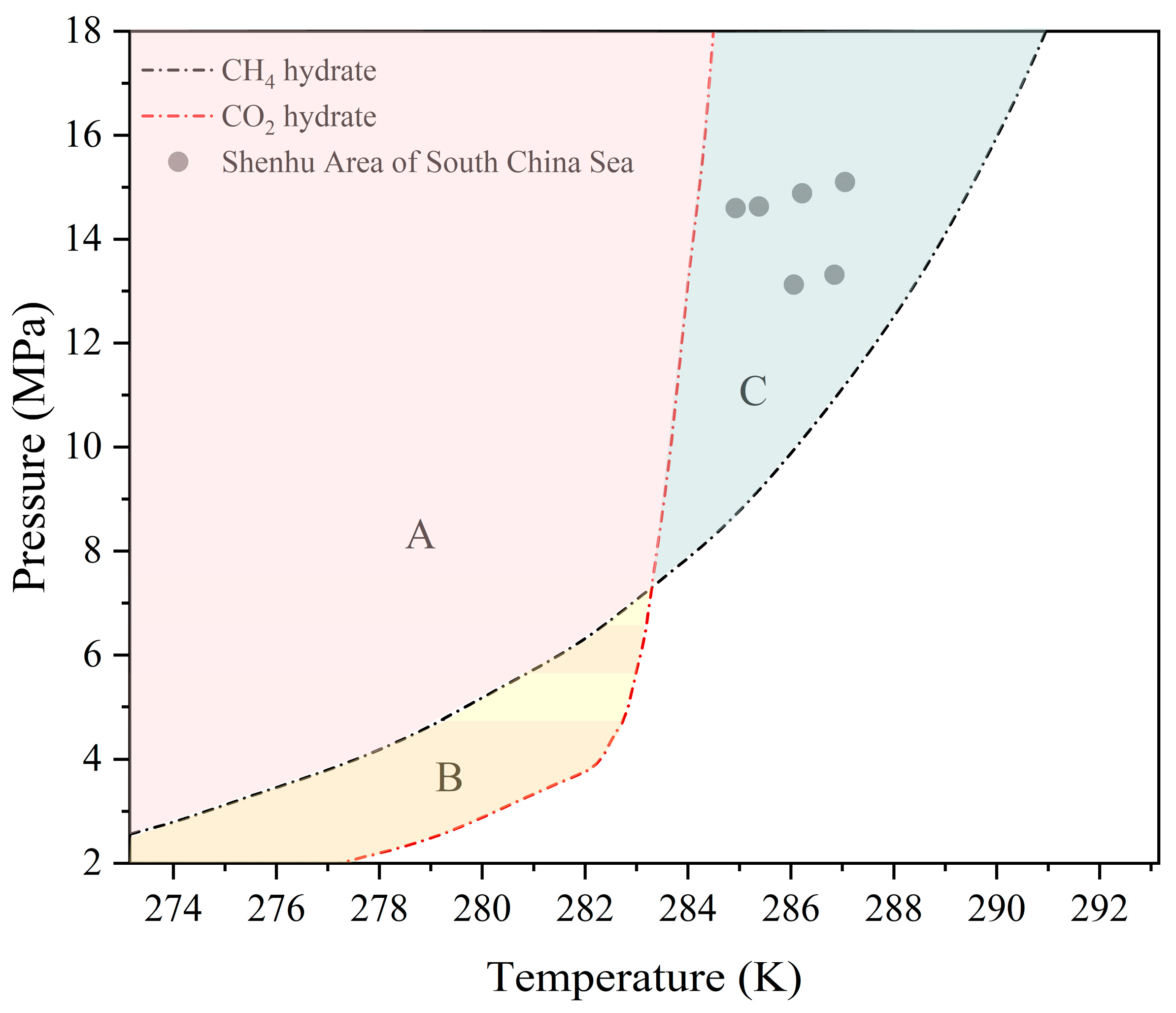
Figure 1. Temperature and pressure conditions in the hydrate area of the South China Sea.
Jmse 13 01977 g001
Figure 2. The distribution of grain size in the sample.
Jmse 13 01977 g002
Figure 3. Schematic diagram of the experiment system.
Jmse 13 01977 g003
Figure 4. Thermobaric path of the sample [34].
Jmse 13 01977 g004
Figure 5. Evolution of P and T during MH formation in Case 1.
Jmse 13 01977 g005
Figure 6. (a) Saturation (SH, SCO2, and SH2O) during MH formation; (b) evolution of permeability during MH formation in Case 1.
Jmse 13 01977 g006
Figure 7. The proportion of methane and replacement rate at the end of MH formation in all cases.
Jmse 13 01977 g007
Figure 8. (a) Gas production in cases 1, 2, and 3; (b) gas production in cases 4, 5, 6, and 7.
Jmse 13 01977 g008
Figure 9. Evolution of CH4 compositions before and after hydrate depressurization in all cases.
Jmse 13 01977 g009
Figure 10. Evolution of permeability and PDR before and after hydrate depressurization in all cases.
Jmse 13 01977 g010
Figure 11. (a) Evolution of CO2 and CH4 compositions in the fluid phase during Mix-H formation in case 1 (The dotted line indicates that the proportion of the material component is zero); (b) Smix-H after 2nd and 3rd replacement in all cases.
Jmse 13 01977 g011
Figure 12. (a) H2O, hydrate, CO2, and CH4 compositions in the samples after Mix-H formation in all cases; (b) CO2 and CH4 compositions in the hydrate phase and retention rate of MH in all cases.
Jmse 13 01977 g012
Figure 13. The average permeability and MHC change rate after Mix-H formation in all cases (The dotted line indicates that the value of HMC is zero).
Jmse 13 01977 g013
Figure 14. Evaluation of Mix-H formation results in all cases.
Jmse 13 01977 g014
Table 1. Summary of experimental conditions and results in all cases.
Title 1Title 2Case 1Case 2Case 3Case 4Case 5Case 6
Pend MPa 13.0013.0013.0013.0013.0013.00
FormationTend K285.15
Final SH %29.3731.4030.8230.7730.5029.77
1st ReplacementPend MPa 13.0013.0013.0013.0013.0013.00
1st ReplacementFinal SMix-H %30.6231.2330.6530.6030.3429.60
1st Depressurization Pend MPa 7.006.005.007.007.007.00
1st DepressurizationFinal SMix-H %24.7021.6118.9922.4220.8638.22
2nd ReplacementPend MPa 13.0013.0013.0013.0013.00
2nd ReplacementFinal SMix-H %39.8236.6335.0941.3638.29
2nd DepressurizationPend MPa 7.006.005.007.007.00
2nd DepressurizationFinal SMix-H %34.6426.8914.3031.8731.75
3rd ReplacementPend MPa 13.0013.0013.0013.0013.00
3rd ReplacementFinal SMix-H %42.2627.9325.2442.8343.20
Disclaimer/Publisher’s Note: The statements, opinions and data contained in all publications are solely those of the individual author(s) and contributor(s) and not of MDPI and/or the editor(s). MDPI and/or the editor(s) disclaim responsibility for any injury to people or property resulting from any ideas, methods, instructions or products referred to in the content.