Article

Research on Collision Avoidance Method of USV Based on UAV Visual Assistance

Navigation College, Dalian Maritime University, Dalian 116026, China
*
Author to whom correspondence should be addressed.
J. Mar. Sci. Eng. 2025, 13(10), 1955; https://doi.org/10.3390/jmse13101955
Submission received: 5 September 2025 / Revised: 2 October 2025 / Accepted: 6 October 2025 / Published: 13 October 2025
(This article belongs to the Section Ocean Engineering)

Abstract

Collision avoidance technology serves as a critical enabler for autonomous navigation of unmanned surface vehicles (USVs). To address the limitations of incomplete environmental perception and inefficient decision-making for collision avoidance in USVs, this paper proposes an autonomous collision avoidance method based on deep reinforcement learning. To overcome the restricted field of view of USV perception systems, visual assistance from an unmanned aerial vehicle (UAV) is introduced. Perception data acquired by the UAV are utilized to construct a high-dimensional state space that characterizes the distribution and motion trends of obstacles, while a low-dimensional state space is established using the USV’s own state information, together forming a hierarchical state space structure. Furthermore, to enhance navigation efficiency and mitigate the sparse-reward problem, this paper draws on the trajectory evaluation concept of the dynamic window approach (DWA) to design a set of process rewards. These are integrated with COLREGs-compliant rewards, collision penalties, and arrival rewards to construct a multi-dimensional reward function system. To validate the superiority of the proposed method, collision avoidance experiments are conducted across various scenarios. The results demonstrate that the proposed method enables USVs to achieve more efficient autonomous collision avoidance, indicating strong potential for engineering applications.

1. Introduction

In the context of the rapid advancement of intelligent shipping and autonomous unmanned systems, unmanned surface vehicles (USVs) have shown considerable application potential in fields such as environmental monitoring and maritime search and rescue, owing to their flexibility and low cost [1]. However, current obstacle avoidance technologies for USVs still face dual challenges. Firstly, the perception systems of single-platform USVs are limited by the field of view of sensors and are susceptible to environmental occlusion, resulting in notable perceptual blind spots in complex scenarios. Secondly, traditional collision avoidance algorithms generally suffer from inefficiencies in path planning and insufficient generalization performance, making it difficult for them to adapt to complex and dynamic navigation environments. In light of these shortcomings in both perception and decision-making, improving the efficient autonomous obstacle avoidance capability of USVs in complex waters has become a crucial technology for overcoming the bottlenecks that restrict their wider application [2,3].
Currently, most USVs rely on lidar for environmental perception to support decision-making for obstacle avoidance [4]. Although lidar can fulfill basic perception requirements in conventional scenarios, it still exhibits certain limitations. Owing to the attenuation of laser wavelengths, the detection range of lidar is generally confined to within 200 meters, which hinders the perception of distant obstacles. More critically, in environments with dense obstacles, lidar has difficulty detecting vessels obscured by other objects, leading to localized perceptual blind spots [5,6]. These perceptual deficiencies considerably compromise the safety of autonomous navigation for USVs.
With the rapid development of the low-altitude economy, an increasing number of researchers have introduced unmanned aerial vehicles (UAVs) into the maritime domain, aiming to leverage their high-altitude perception advantages to compensate for the limitations of USVs in environmental perception [7,8]. For instance, Wang et al. proposed a vision-based collaborative search-and-rescue system involving UAVs and USVs, in which the UAV identifies targets and the USV serves as a rescue platform, navigating to the target location to execute rescue operations [9]. Li et al. implemented cooperative tracking and landing between UAVs and USVs using nonlinear model predictive control, ensuring stable tracking of USVs by UAVs and enabling remote target detection in maritime combat systems [10]. Zhang et al. developed a cooperative control algorithm for USV-UAV teams performing maritime inspection tasks, achieving coordinated path following between the vehicles [11]. Chen et al. integrated visual data from USVs and UAVs with multi-target recognition and semantic segmentation techniques to successfully detect and classify various objects around USVs, as well as to accurately distinguish navigable from non-navigable regions [12]. Despite these significant achievements, existing studies predominantly treat UAVs as external sensing units and fall short of effectively integrating perceptual information into USVs’ decision-making systems. This limitation curtails the potential of UAVs to enhance the autonomous navigation capabilities of USVs. Consequently, there is a pressing need to develop methodologies that embed UAV-derived perceptual information into the obstacle avoidance decision-making process of USVs, thereby extending their environmental perception range and improving navigation safety in complex aquatic environments.
In the domain of collision avoidance algorithms for USVs, traditional path planning methods continue to encounter significant challenges. Although the A* algorithm guarantees globally optimal paths, its high computational complexity in high-dimensional dynamic environments leads to inadequate real-time performance [13]. The RRT* algorithm provides probabilistic completeness but exhibits limitations in path smoothness and dynamic adaptability [14]. The dynamic window approach (DWA) is susceptible to local optima, primarily due to its dependence on local perception information for velocity space sampling [15]. Meanwhile, the velocity obstacle (VO) method demands high precision in obstacle motion prediction and often demonstrates delayed responses in complex dynamic environments [16]. In summary, these conventional approaches rely on manually predefined rules and model parameters, resulting in limited generalization capability in complex scenarios, which directly constrains the efficiency of USV decision-making for collision avoidance.
Breakthroughs in artificial intelligence have opened new pathways for collision avoidance research in USVs through learning-based intelligent decision-making methods [17,18,19]. Among these, deep reinforcement learning (DRL) algorithms optimize navigation policies through continuous interaction with complex dynamic environments, leveraging autonomous learning mechanisms to enhance generalization capability in unknown scenarios. As a result, DRL has been widely adopted for ship collision avoidance tasks [20,21,22]. For instance, Chen et al. developed a Q-learning-based path planning algorithm that enabled USVs to achieve autonomous navigation through iterative policy optimization, without relying on manual expertise [23]. However, Q-learning was susceptible to the curse of dimensionality in high-dimensional state spaces. The Deep Q-Network (DQN) mitigated computational burden by substituting Q-tables with deep neural networks. Fan et al. implemented an enhanced DQN for USV obstacle avoidance, reporting favorable performance in dynamic settings [24]. Despite these advances, DQN and other value-based DRL algorithms operate on discrete action spaces, which limits fine-grained and continuous control in obstacle avoidance behavior and often results in oscillatory trajectories [25].
To address the limitations of discrete action spaces, policy gradient-based deep reinforcement learning methods have increasingly become a research focus. These approaches leverage an Actor network to directly output continuous actions, thereby substantially enhancing control precision. For example, Cui et al. enhanced the Twin Delayed Deep Deterministic Policy Gradient algorithm by incorporating multi-head self-attention and Long Short-Term Memory mechanisms, constructing a historical environmental information processing framework that improves the stability of continuous action generation in complex environments [26]. Lou et al. combined the dynamic window approach and velocity obstacle method within the Deep Deterministic Policy Gradient framework to optimize the reward mechanism, achieving a multi-objective balance between collision avoidance safety and navigation efficiency [27]. Xu et al. integrated a prioritized experience replay strategy into DDPG, dynamically adjusting sample weights to expedite training convergence in critical collision avoidance scenarios [28]. Despite these advancements, the aforementioned methods still exhibit certain limitations regarding training stability, convergence efficiency, or sensitivity to hyperparameters.
In contrast, the proximal policy optimization (PPO) algorithm significantly enhances training stability and convergence reliability by utilizing importance sampling and a policy clipping mechanism. Xia et al. constructed a multi-layer perceptual state space and incorporated convolutional neural networks, demonstrating the effectiveness of PPO in complex obstacle avoidance scenarios [29]. Sun et al. further extended its environmental perception capability, enabling stronger generalization performance in unfamiliar waters [30]. Although these studies show promising results, the design of their reward functions remains subject to notable limitations. Firstly, reward function design often relies heavily on researchers’ empirical knowledge, lacking a systematic theoretical foundation and interpretability. Secondly, most existing works focus predominantly on collision avoidance safety while overlooking other navigation metrics such as path smoothness [31]. This inadequacy not only leads to convoluted USV trajectories but also causes low learning efficiency during training due to sparse-reward problems [32]. These limitations substantially constrain further improvement of overall algorithm performance. Consequently, developing a theoretically sound, highly interpretable, and multi-objective balanced reward mechanism has emerged as a crucial research direction for advancing the performance of unmanned surface vehicle collision avoidance systems.
To address the aforementioned challenges, this paper proposes an obstacle avoidance scheme for USVs incorporating vision assistance from a UAV, and develops the DWA-PPO (DPPO) collision avoidance algorithm. The principal contributions of this work are summarized as follows:
(1). By leveraging the high-altitude perspective of UAVs, a high-dimensional state space characterizing obstacle distribution is constructed. This representation is integrated with a low-dimensional state space derived from the USV’s own state information, forming a hierarchical state space framework that enhances the comprehensiveness and reliability of environmental information for decision-making during navigation.
(2). By integrating DWA’s trajectory evaluation, a multi-layered dense reward mechanism is established, combining heading, distance, and proximity rewards with COLREGs-based compliance incentives to guide USVs toward safe, efficient, and regulation-compliant collision avoidance.
The remainder of this paper is organized as follows. Section 2 introduces the mathematical models of UAV/USV and COLREGs, and constructs the collision risk assessment model. Section 3 provides a detailed description of the proposed collision avoidance method. The design of simulation experiments and analysis of results are presented in Section 4. Finally, Section 5 concludes the paper and outlines future research directions.

2. Materials and Methods

2.1. Mathematical Models of UAV and USV

To describe the UAV and USV models, a coordinate system architecture as shown in Figure 1 is established. The O E X E Y E Z E represents the inertial coordinate system, with its origin O E fixed at a specific point. Assuming that both the UAV and the USV are rigid bodies, the coordinate systems O a X a Y a Z a and O s X s Y s Z s denote the body coordinate system and the USV-attached coordinate system, respectively, with their origins O a and O s positioned at the respective centers of mass. Based on the above coordinate system architecture, the mathematical models of the UAV and the USV are established as follows:
m a x ¨ a = T ( cos ψ a sin θ a cos ϕ a + sin ψ a sin ϕ a ) k d x ˙ a m a y ¨ a = T ( sin ψ a sin θ a cos ϕ a cos ψ a sin ϕ a ) k d y ˙ a m a z ¨ a = T cos θ a cos ϕ a m a g k d z ˙ a I ax ϕ ¨ a = τ ϕ ( I a z I ay ) q a r a k d ϕ ˙ a I ay θ ¨ a = τ θ ( I ax I az ) p a r a k d θ ˙ a I az ψ ¨ a = τ ψ ( I ay I ax ) p a q a k d ψ ˙ a
x ˙ s = u s cos ψ s v s sin ψ s y ˙ s = u s sin ψ s + v s cos ψ s ψ ˙ s = r s r ˙ s = r s T s + K T s δ + f f = f n + f m
In Equation (1), m a is the total mass of the UAV, [ x a , y a , z a ] T represents the position of the UAV in the inertial coordinate system, [ ϕ a , θ a , ψ a ] T denote the roll, pitch, and yaw angles of the UAV, T is the total thrust generated by the rotors, [ I ax , I ay , I az ] T is the moment of inertia of the UAV, [ p a , q a , r a ] T is the angular velocity of the UAV in the body coordinate system, k d is the air resistance coefficient.
In Equation (2), [ x s , y s , ψ s ] T represents the ship’s position and heading angle in the inertial frame, [ u s , v s , r s ] T denote the longitudinal velocity, lateral velocity, and angular velocity around the z-axis in the body-fixed frame, respectively. T s is the yaw response time constant, K is the maneuverability index, f represents disturbances caused by unmodeled dynamics, f n denotes inherent uncertainties in the internal model, and f m stands for uncertain external disturbances. δ is the rudder angle. A change in the rudder angle δ will alter the forces acting on the ship, which in turn affects the angular velocity, thereby achieving the steering operation of the ship.

2.2. Ship Domain Model

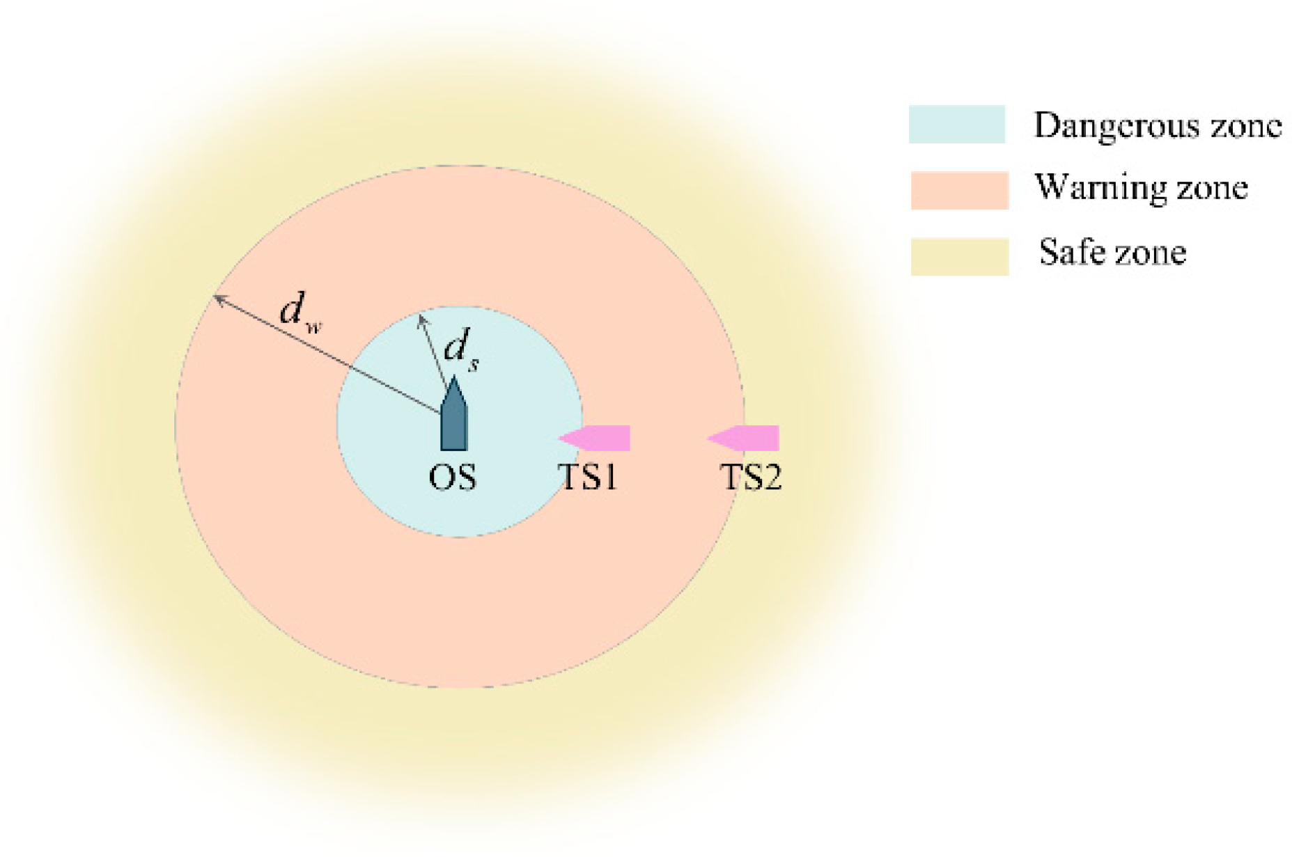
The ship domain serves as a critical criterion for assessing collision risk at sea. The potential intrusion of another vessel into this domain signifies a substantial increase in collision risk, making immediate collision avoidance preparations mandatory. This paper draws on the ship domain research of Lou et al. for USVs and constructs a concentric circular ship domain model based on the Distance to Closest Point of Approach (DCPA), as illustrated in Figure 2 [27]. The model is centered on the USV and radiates outward. It uses DCPA thresholds to define different risk zones: d s is set as the boundary threshold between the danger zone and the warning zone, and d w as the threshold between the warning zone and the safe zone. These two distance thresholds allow for a clear distinction among various collision risk levels. The characteristics of each zone and the corresponding collision avoidance strategies are described as follows:
Safe zone: Defined with d w as the inner boundary, the USV possesses sufficient controllable maneuvering space within this region, making collision avoidance measures unnecessary.
Warning zone: Situated between d w and d s , this is the critical threshold interval for collision decision-making. If the DCPA decreases over time, it indicates an increasing collision risk, and the USV must enter a preparedness state for collision avoidance to prevent entering the danger zone.
Dangerous zone: Defined with d s as the outer boundary, when other ships enter this region, they pose a direct threat to the navigation safety of the USV, necessitating immediate emergency collision avoidance measures.
Based on the above ship domain division, the USV can execute differentiated collision avoidance strategies according to the zone it is in, enabling precise prevention and control of collision risks.

2.3. COLREGs

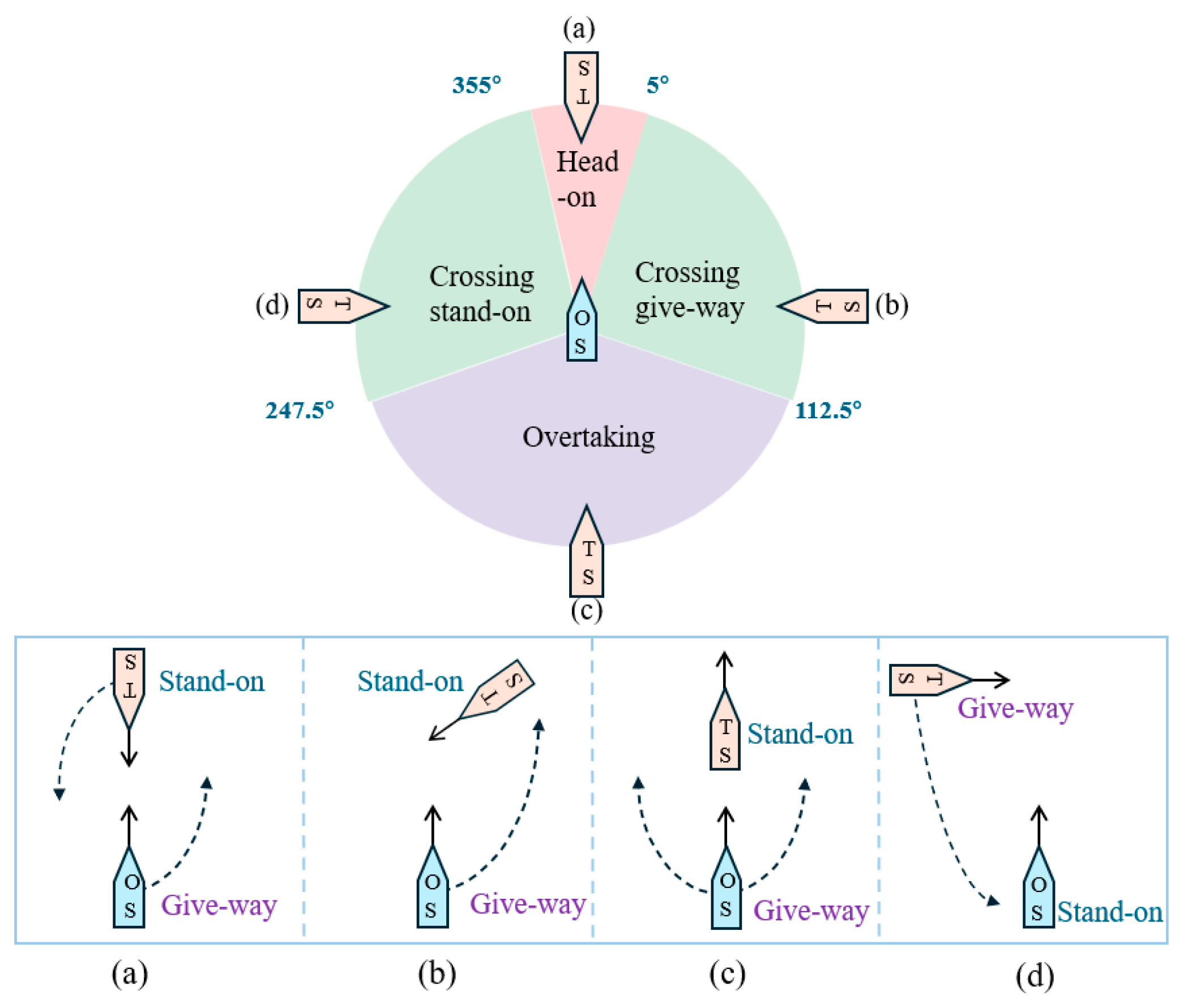
The core objective of COLREGs is to standardize ship operations to prevent maritime collisions. In the research of autonomous USV collision avoidance, strictly adhering to COLREGs rules is fundamental to ensuring safe navigation [28]. This paper focuses on rules 13 to 17, which are directly related to ship collision avoidance. These rules clearly define the responsibilities for collision avoidance in three typical encounter scenarios: head-on encounter, overtaking encounter, and crossing encounter. As shown in Figure 3, in a head-on encounter, both ships must turn to starboard. During an overtaking encounter, the overtaking ship is the give-way ship. In a crossing encounter, the ship with another ship on its starboard side is the stand-on ship, while the ship with another ship on its port side is the give-way ship.

3. Proposed Approach

3.1. Improved PPO Algorithm

The PPO algorithm, relying on the importance sampling and policy clipping mechanisms, significantly enhances stability and reduces the sensitivity to hyperparameters, and performs excellently in the USV collision avoidance scenario [22,29,30]. However, this algorithm has problems of low sample efficiency and an imbalance between exploration and exploitation, and further optimization is still needed.
The core goal of PPO is to solve the optimal policy to maximize the expected value of the long-term cumulative discounted reward. Its objective function is:
J ( θ ) = E τ ~ π θ t = 0   γ t r t
where s t is the environmental state at time t   , a t is the action executed by the intelligent agent, r t is the immediate reward, and γ is the discount factor.
According to the policy gradient theorem, the gradient of the objective function is expressed as:
θ J ( θ ) = E τ ~ π θ t = 0 θ log π θ ( a t | s t ) A π θ ( s t , a t )
where A π ( s t , a t ) is the advantage function, which is used to guide the policy gradient update direction.
To address the problem of low sample efficiency of traditional policy gradient algorithms, PPO introduces the importance sampling technique, allowing the use of samples generated by the old policy to optimize the new policy. At this time, the objective function is converted to:
J ( θ ) = E τ ~ π θ old π θ ( a t | s t ) / π θ old ( a t | s t ) A π θ old ( s t , a t )
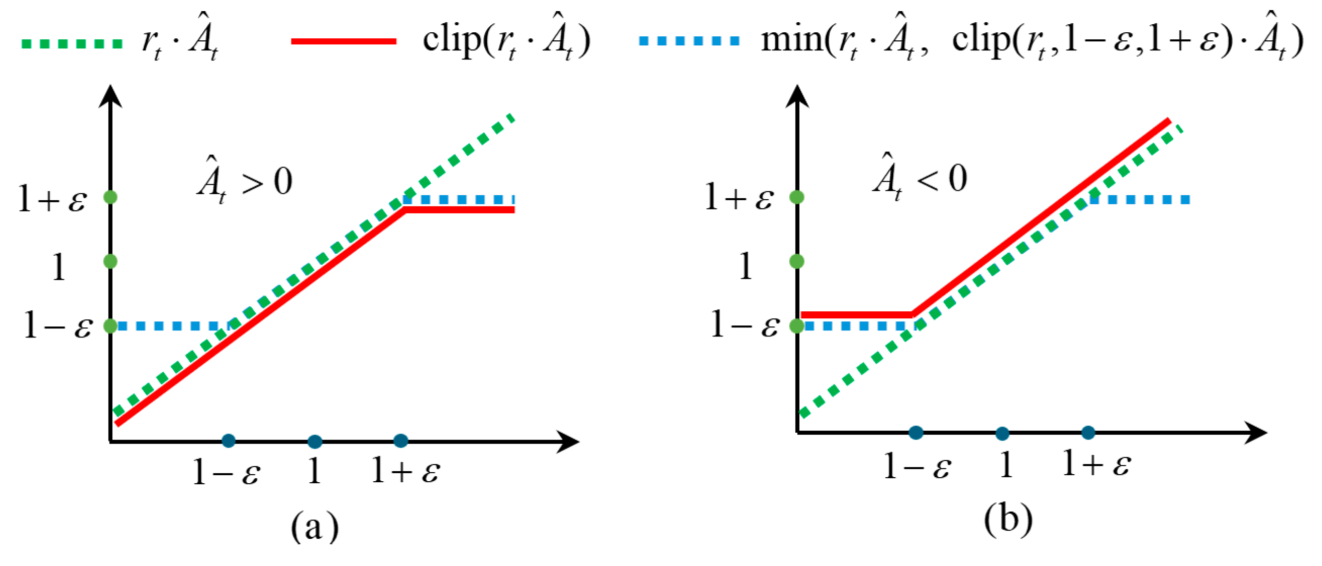
To prevent the performance degradation caused by an overly large policy update step, PPO adopts a clipping mechanism and modifies the objective function to:
J clip ( θ ) = E [ min r t ( θ ) A ^ t , clip r t ( θ ) , 1 ε , 1 + ε ) A ^ t ) ]
where r t ( θ ) = π θ ( a t | s t ) / π old ( a t | s t ) represents the policy probability ratio, A ^ t is the estimated value of the advantage function, clip ( ) is the clipping function, which limits the probability ratio within the interval [ 1 ε , 1 + ε ] , and ε is a hyperparameter. The two clipping situations are shown in Figure 4.
To further enhance the exploration capability of the algorithm, this paper introduces a policy entropy improvement mechanism into PPO, which broadens the policy search space to increase the probability of discovering potential return policies. The improved objective function is:
L ( θ ) = J clip ( θ ) c 1 L V F ( θ ) + c 2 S [ π θ ]
where S [ π θ ] represents the policy entropy, c 1 is the weight coefficient of the value function loss, c 2 is the entropy coefficient, and L V F ( θ ) is the value function loss, with the mathematical expression:
L V F ( θ ) = E V θ ( s t ) R ^ t 2
where R ^ t is the generalized advantage estimate.
Finally, the algorithm achieves a balance by simultaneously optimizing the policy objective and the value function loss. Its complete optimization objective is:
L ( θ ) = E min r t ( θ ) A ^ t , clip ( r t ( θ ) , 1 ε , 1 + ε ) c 1 ( V θ ( s t ) R ^ t ) 2 + c 2 S [ π θ ]

3.2. State Space Design

State space design is a core component of collision avoidance decision-making for USVs, and its representational capability directly impacts the algorithm’s decision-making performance. This paper divides the state space into two parts: a high-dimensional state space and a low-dimensional state space, aiming to achieve precise characterization of environmental information.
The high-dimensional state space is designed to characterize the spatial distribution and dynamic variations in obstacles surrounding the USV, thereby providing foundational environmental perception support for subsequent collision avoidance decision-making processes. To mitigate the limitations of USV-borne sensors, which are prone to occlusion in complex maritime environments, this study leverages the high-altitude visual perception capability of UAV and primarily constructs the high-dimensional state space using UAV-acquired image data. The design of this state space is predicated on the following core premise: the UAV can maintain stable tracking of the USV with minimal tracking errors while simultaneously capturing environmental information centered on the USV [33,34,35]. To fulfill this premise, the nonlinear model predictive control (NMPC) approach proposed in Reference [10] is adopted herein to ensure reliable and stable tracking of the USV by the UAV.
In terms of specific implementation, the onboard camera mounted on the UAV collects real-time overhead environmental images centered on the USV, with a coverage area of 400 m × 400 m. The resolution of these images is optimally designed to clearly distinguish the contour features and position information of both static obstacles and dynamic targets in the water area [36]. It is worth noting that relying solely on a single-frame image fails to capture the movement trends of obstacles, which is likely to cause the decision-making system to misjudge dynamic risks. To address this issue, this paper introduces a sliding time window mechanism. By extracting a sequence of three consecutive frames of time-series images, a high-dimensional state space is constructed. The high-dimensional state space is defined as S high :
S high = [ I t 2 ,   I t 1 ,   I t ]
where I t ,   I t 1 , and I t 2 respectively represent the image information collected at time t , time t 1 , and time t 2 .
The low-dimensional state space is primarily used to supplement the USV’s own state information, including its position ( x s , y s ) , heading angle ψ s , and target location ( x target , y target ) . Since such information is not suitable for representation in image form, the low-dimensional state space is constructed based on data collected by the USV’s onboard sensors. The low-dimensional state space is defined as S low :
S low = [ x s , y s , ψ s , x target , y target ]

3.3. Actor Space Design

The design of the action space takes full account of the physical characteristics of the USV’s actual control system, selecting a continuous set of rudder angles δ [ 20 ,   20 ] as the algorithm’s action space A . At each decision step, the algorithm outputs a scalar action, representing the desired rudder angle at the current timestep. According to Equation (2), changes in the rudder angle directly affect the USV’s angular turning rate, enabling it to adjust its heading for effective obstacle avoidance or autonomous navigation toward the target.

3.4. Neural Network Architecture

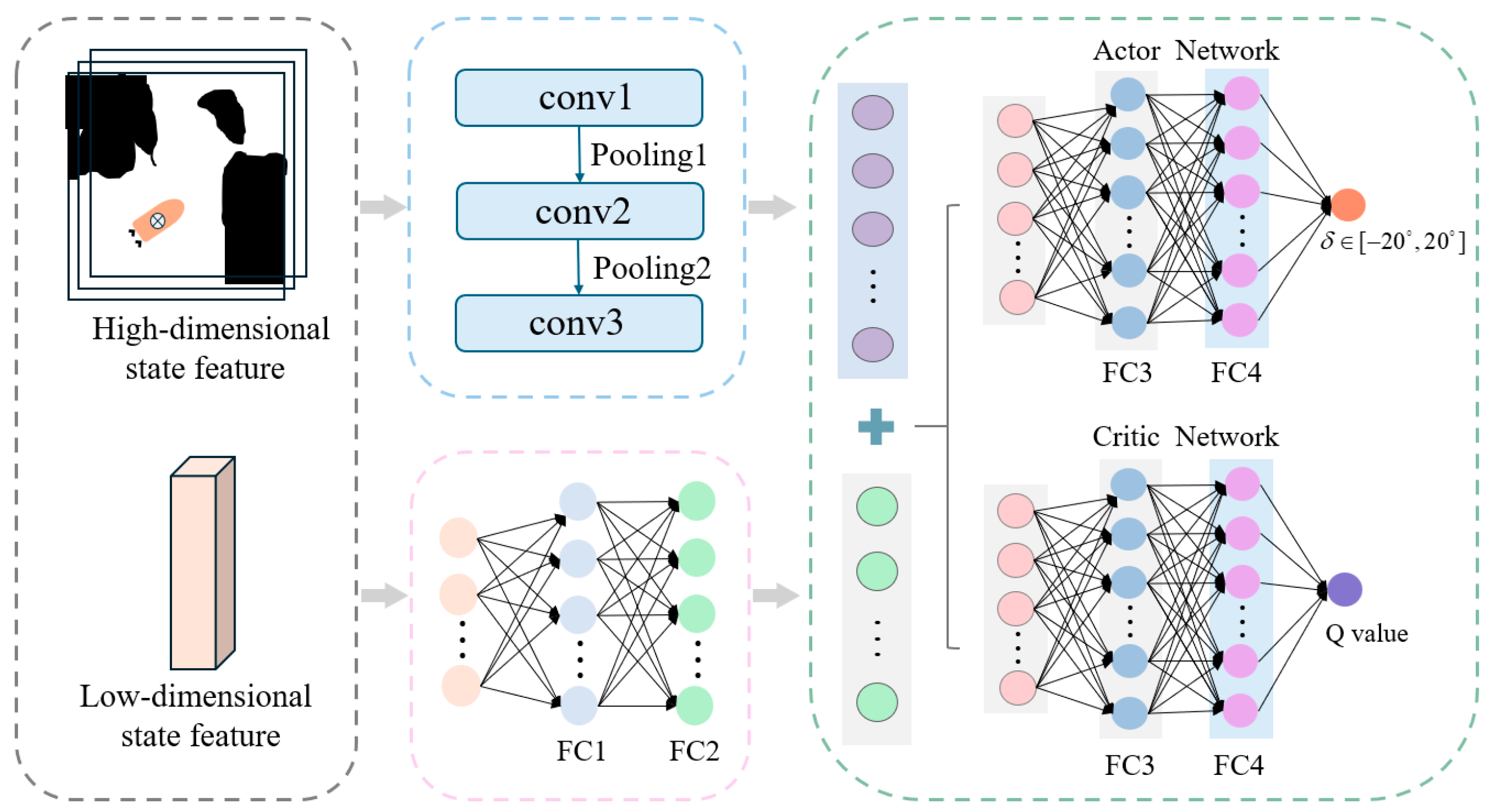
The neural network architecture is designed with multi-level feature fusion as its core, enabling precise characterization and efficient decision-making in complex aquatic environments through the collaborative processing of high-dimensional and low-dimensional state information. The detailed architecture is shown in Figure 5.
For the high-dimensional state space derived from image data, feature extraction is performed using a three-layer convolutional neural network. The first convolutional layer utilizes 16 filters of size 3 × 3 with a stride of 2, followed by a ReLU activation function and a 2 × 2 max-pooling operation, to capture initial local features representing obstacle distribution and motion trends. The second layer employs 32 filters of size 3 × 3 with a stride of 2, further enhancing feature abstraction while reducing dimensionality via an additional max-pooling layer. The third layer consists of 64 filters of size 3 × 3 with a stride of 1, producing a high-dimensional feature map that is subsequently flattened into a one-dimensional feature vector, thereby preserving information on both the static distribution and dynamic movement patterns of obstacles.
For the low-dimensional state space, a two-layer fully connected network is used. The first layer maps the raw low-dimensional vector into a 64-dimensional feature space, and the second layer compresses it into a 32-dimensional vector, improving nonlinear feature expression and producing the final low-dimensional feature vector.
The high-dimensional and low-dimensional feature vectors are concatenated to form a fused feature vector, which is then fed into both the Actor network and the Critic network. The Actor network consists of three fully connected layers: the first two use ReLU activation, while the final layer applies a Tanh activation function to output a continuous rudder angle, directly guiding the USV’s steering actions. The Critic network also has three fully connected layers, used to evaluate the current policy and provide guidance for policy updates. Detailed network parameter configurations are listed in Table 1.

3.5. The Novel Reward Mechanisms

The design of the reward function directly dictates the convergence efficiency and decision-making performance of the agent’s policy. In this paper, on the basis of setting the collision penalty and the terminal reward R core as the main rewards, a process reward R DWA based on the trajectory evaluation function of the DWA is introduced to furnish denser feedback signals for the USV [32]. Meanwhile, to incentivize collision-avoidance behaviors that conform to COLREGs, a dedicated COLREGs reward R COLREGs is devised as an additional auxiliary mechanism, guiding the USV to realize safe and compliant autonomous collision avoidance in complex environments. The structure of the reward is as follows:

3.5.1. Process Rewards

The process reward R DWA generates dense feedback signals by quantifying the navigation status in real time. This reward is designed based on the content of Section 3.1, and consists of three components: heading angle reward, obstacle distance reward, and goal proximity reward. The specific design is as follows:
(1). Heading Angle Reward: By quantifying the deviation between the USV’s current heading and the target direction, a continuous directional guidance signal is provided. A positive reward is given when the USV’s heading approaches the target direction, while negative rewards are applied to suppress inefficient paths if significant detours occur. R head is defined as follows:
R head = λ 1 | ψ s ψ g | π
where λ 1 is the weight of the heading reward, ψ s is the current heading angle, and ψ g represents the bearing angle of the target position relative to the USV.
(2). Obstacle Distance Reward: Based on the layered logic of the risk zones (dangerous zone, warning zone, and safe zone) defined in the ship domain model in Section 2.2, a dynamic reward mechanism is designed. When an obstacle vessel is in the danger or warning zone, a distance-based linear penalty is applied, with a higher weight assigned to the danger zone. No penalty is imposed when the obstacle is in the safe zone, thereby reinforcing distinct reward and penalty guidance across different zones. R obs is defined as follows:
R obs = λ 2 ( 1 d d s ) ,   if   d d s λ 3 ( 1 d d s d w d s ) ,   if   d s < d < d w 0 ,     if   d d w
where λ 2 and λ 3 are the reward weights for the dangerous zone and the warning zone, respectively, and d is the distance between the USV and the obstacle.
(3). Target Proximity Reward: Evaluate the change in Euclidean distance between the USV and the target point. If the distance to the target at the current moment is closer than that at the previous moment, a positive reward is given to incentivize continuous approach to the target, if operations such as obstacle avoidance cause the distance to increase, negative rewards are used to constrain excessive detour behaviors. R d i s t is defined as follows:
R dist = λ 4 ( d pre d cur )
where λ 4 is the weight of the target proximity reward, d cur denotes the distance from the USV to the target position at the current moment, and d pre represents the distance from the USV to the target position at the previous moment.
Remark 1.
The determination of reward function weights combines task priority analysis with experimental tuning. Firstly, according to the relative significance of each navigation objective, the initial value ranges of the coefficients are defined to ensure that the rewards for core tasks play a dominant role in the learning signal. Subsequently, via a series of controlled experiments, the optimal configuration of the reward coefficients is ascertained to optimize path efficiency. Ultimately, this approach guarantees that the reward function can effectively guide the USV to make safe and efficient obstacle-avoidance decisions.

3.5.2. Collision and Arrival Reward

Collision rewards enhance navigation safety through negative reward to prevent collisions, while arrival rewards provide positive incentives upon achieving the target to clarify navigation objectives. Together, they form the fundamental framework of the reward function, ensuring the safety and task orientation of obstacle avoidance behaviors. R core is defined as follows:
R core = k arr ,   if   ( P USV )   =   ( P goal ) k col ,    if   c o l l i s i o n 0 ,     otherwise
where k arr represents the arrival reward value, k col denotes the arrival reward value, P USV signifies the position of the USV, and P goal indicates the target position.

3.5.3. COLREGs Reward

The COLREGs reward R COLREGs , based on COLREGs Articles 13–17, guides the USV to execute collision-avoidance actions in compliance with regulations during interactive decision-making. A negative reward is given if the USV’s collision-avoidance violates COLREGs rules. R COLREGs is defined as follows:
R COLREGs = k COLREGs ,  if   v i o l a t e s   C O L R E G s   0 ,      else
where k C O L R E G s denotes the reward value complying with COLREGs rules.
The overall reward structure is as follows:
R total = R DWA + R core + R COLREGs R DWA = R head + R obs + R dist
Remark 2.
Considering conventional reward mechanisms, the USV usually obtains explicit reward signals only when a collision occurs or it successfully reaches the target, while effective guidance is lacking during intermediate navigation phases. This frequently leads to aimless random exploration, considerably prolonging the training cycle. In this paper, a process reward based on the DWA algorithm is introduced, which provides continuous and real-time feedback in three dimensions—heading angle deviation, obstacle distance, and target proximity—thus offering full-course navigation guidance for the USV. This approach effectively reduces ineffective exploration and speeds up policy convergence. Furthermore, by integrating reward terms corresponding to COLREGs rules with the process reward, a dual-constraint mechanism that balances navigation efficiency and regulatory compliance is established, ultimately yielding a collision avoidance strategy that is both efficient and compliant with COLREGs rules.

3.6. The Algorithm Flow of DPPO

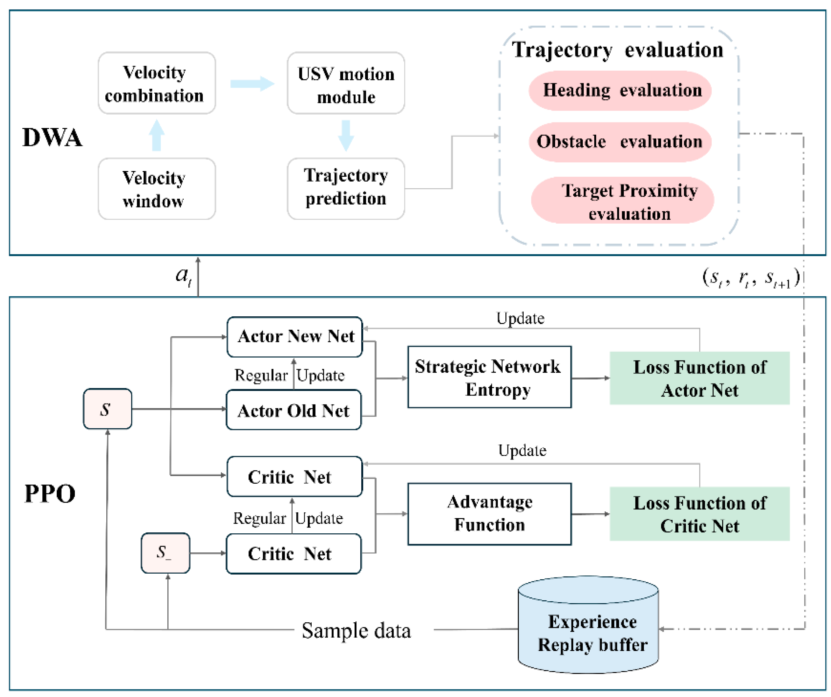
The algorithmic flow of DPPO is illustrated in Figure 6 and primarily consists of three stages.
In the initial phase, the parameters of the policy network and value network are initialized, hyperparameters such as the discount factor and clipping coefficient are set, and an experience buffer D is established to store transitions ( s t , a t , r t , s t + 1 ) .
During the second stage, the actor network generates an action a t based on the current state s t . This action is executed to produce a predicted trajectory. The reward r t is then calculated using the reward function designed based on the DWA trajectory evaluation. The next state s t + 1 is obtained, and the transition ( s t , a t , r t , s t + 1 ) is stored in the experience buffer D .
In the third stage, sample data from the experience pool D , and combine it with the output of the value network to compute the advantage function A t and the target return using GAE. Record the probability of action a t under the old policy π old . Based on the PPO clipping mechanism, calculate and clip the probability ratio of a t under the new and old policies to obtain the policy loss J clip , while also computing the value loss L V F . Introduce the policy entropy S [ π θ ] and combine it with J clip and L V F through weighted summation to form the total loss. Employ gradient descent to update the network parameters, and iterate over multiple rounds until the policy converges.

4. Experimental Validation

4.1. Simulation Environment and Parameter Configuration

The experiment is based on the ROS Noetic simulation platform, constructing a USV collision avoidance scenario in GAZEBO. The training environment is deployed on a computer equipped with an Intel Core i7-13700K CPU, NVIDIA RTX 4070 Ti GPU, and 32 GB of RAM, running the Ubuntu 20.04 LTS operating system. The software dependencies include Python 3.8 and the PyTorch 1.12.1 framework. The model training parameters are shown in Table 2. The model parameters of the UAV and USV are shown in Table 3.

4.2. Training Analysis of DPPO Algorithm

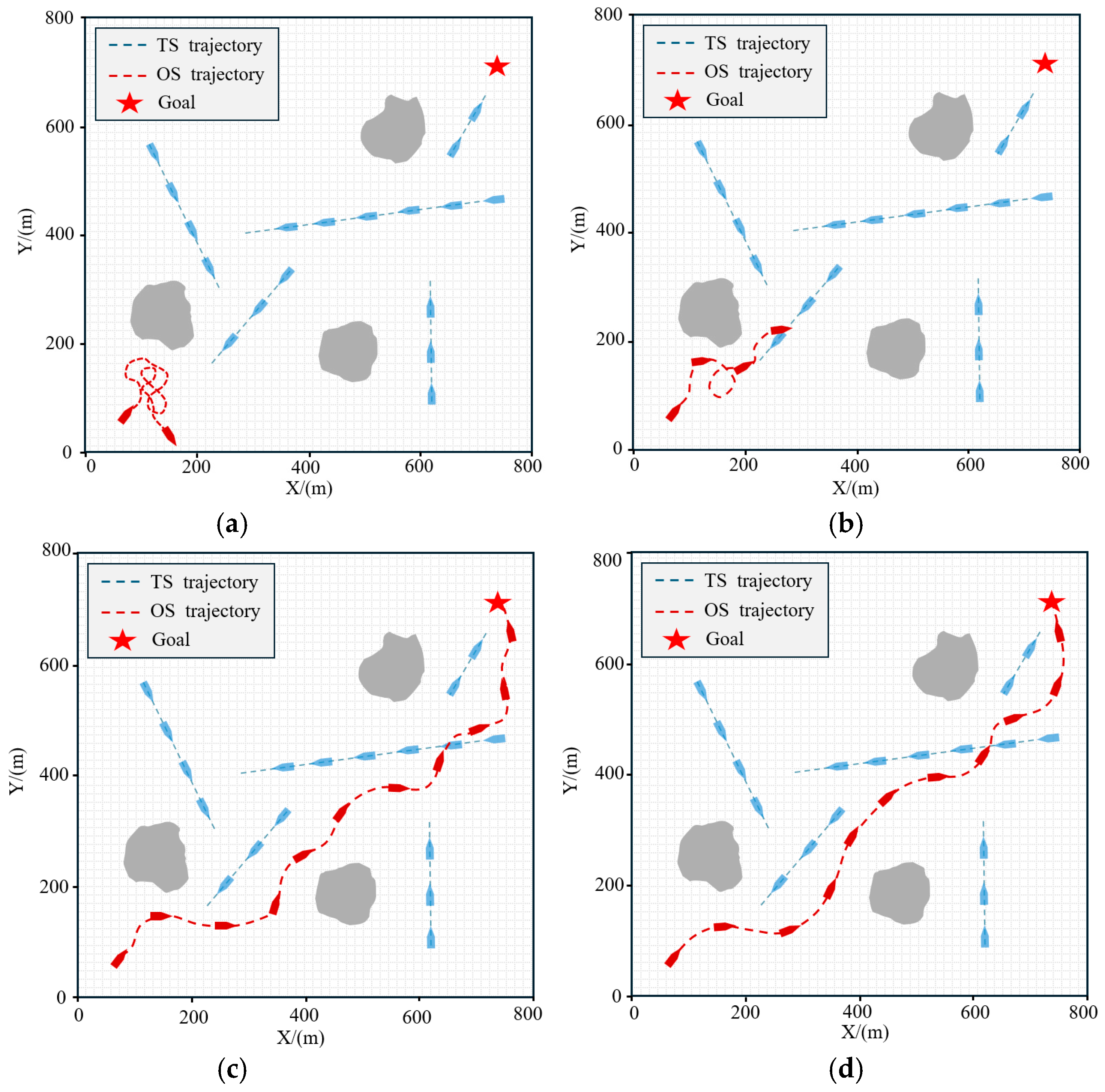
The collision avoidance performance of the model evolves significantly across different training phases, as illustrated in Figure 7. During the initial stage (100 episodes), the USV fails to develop an effective obstacle avoidance strategy, exhibiting aimless random movements (Figure 7a). By the 1000th episode, the USV begins to coarsely identify the target direction and navigate toward it exploratively (Figure 7b). At 4000 episodes, the USV acquires the fundamental capability to complete obstacle avoidance tasks, although its trajectory still displayed noticeable detours (Figure 7c). Upon reaching 6000 episodes, the model’s performance improves markedly, enabling the USV to reach the target via smooth and efficient trajectories while executing precise collision avoidance maneuvers for both static and dynamic obstacles (Figure 7d).
To further quantify the training performance from a numerical perspective, a comparative analysis was conducted. In DRL, the agent’s primary objective is to maximize long-term cumulative rewards through continuous policy optimization; thus, the cumulative reward serves as a key metric for evaluating model convergence [37].
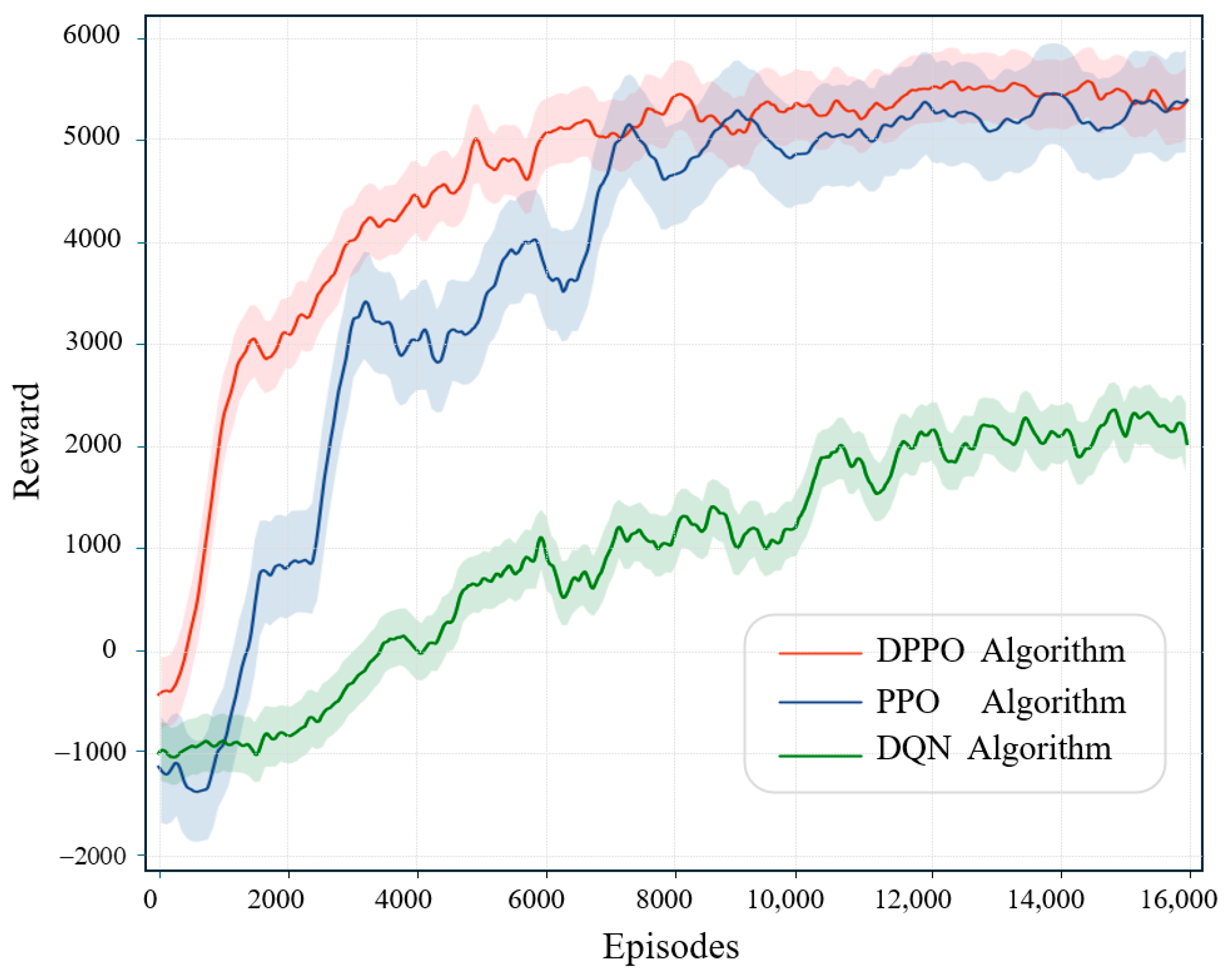
Based on this, comparative experiments were performed on the DPPO, PPO, and DQN algorithms within the training scenario. The cumulative reward curves for the different algorithms are illustrated in Figure 8. The results indicate that the DPPO algorithm converges at approximately 6200 episodes, which is 19.6% and 38.1% faster than the PPO and DQN algorithms, respectively. Furthermore, the converged DPPO algorithm achieves a higher final cumulative reward than PPO. These results robustly validate the superior training performance of the DPPO algorithm.

4.3. Verification of UAV Tracking the USV

The effectiveness of the proposed DPPO collision avoidance algorithm hinges on the UAV’s capability to stably track the USV. To verify the feasibility of this prerequisite, this section assesses the UAV’s tracking performance of the USV in a simulation environment. In the experiment, the USV navigates along a preset trajectory from the initial position (200, 200) to the target position (700, 700). Meanwhile, the UAV, maintaining a constant altitude of 60 meters, employs the NMPC method cited in Section 3.2 to track the USV. To simulate uncertainties in real marine environments, the experiment introduces random wind field disturbances with an average wind speed of 5 m/s and injects Gaussian white noise with a standard deviation of 0.5 meters into the UAV’s GPS positioning data.
The tracking results are presented in Figure 9a. Throughout the entire navigation process, the UAV exhibits excellent tracking stability. The tracking error—defined as the horizontal Euclidean distance between the UAV and the USV—is plotted against time in Figure 9b. Quantitative analysis reveals that under the influence of environmental disturbances and sensor noise, the UAV achieves an average tracking error of 2.1 m and a maximum tracking error of 4.3 m. Given that the visual perception range configured in this study is 400 m × 400 m, the maximum tracking error accounts for merely approximately 1% of the perception area width. This level of deviation will not result in the USV exiting the UAV’s perceptual field of view, thereby satisfying the requirements of the vision-assisted collision avoidance algorithm for perception continuity and coverage. The aforementioned results confirm that under typical environmental disturbance conditions, the NMPC-based UAV tracking controller exhibits sufficient robustness and accuracy, which in turn guarantees the core prerequisite for the implementation of the vision-assisted collision avoidance method.
Remark 3.
Although the simulation experiments verify that the UAV can achieve stable tracking of the USV with acceptable errors under 5 m/s wind speed and GPS noise interference, this conclusion has significant limitations in real-world marine environments. Under actual sea conditions, particularly moderate to high sea states, the conditions for UAV takeoff, landing, and sustained flight are often unmet. Consequently, the prerequisite of relying on UAVs for vision-assisted perception ceases to hold, severely limiting the applicability of the proposed DPPO method under harsh weather conditions. Future research needs to further explore alternative perception schemes for when UAVs are unavailable, thereby enhancing the system’s robustness across all weather and sea conditions.

4.4. Collision Avoidance Simulation Verification

To evaluate the collision avoidance performance of the proposed DPPO algorithm, a series of simulation environments are constructed, including three typical ship encounter scenarios (head-on, overtaking, and crossing give-way), multi-ship collision avoidance scenarios, as well as complex scenarios with visual obstructions. On this basis, the proposed algorithm is compared and analyzed against the VO method [16], the DWA [13], the DQN algorithm [24], and the PPO algorithm [22].
To quantitatively evaluate the collision avoidance performance of different algorithms, the path length L path , cumulative heading change H sum , and the minimum distance between the own ship and obstacle ships D min are selected as evaluation metrics [31]. Here, L path represents the cumulative sailing distance, measuring the global optimality of the path. H sum reflects the intensity of heading adjustments, indicating the algorithm’s ability to control sailing stability. D min assesses collision avoidance safety. Generally, smaller values of L path and H sum indicate higher sailing efficiency and stability. It is noteworthy that while a larger minimum distance between the own ship and obstacle ships theoretically implies greater safety, excessive detours may lead to increased energy consumption costs. Therefore, a reasonable safety threshold d safe is established. When the minimum distance falls below this threshold, the collision avoidance safety is deemed insufficient. Based on Wang et al.’s method for calculating the minimum safe passing distance for USVs, combined with the USV data analysis, the theoretical minimum collision avoidance distance is approximately 30 m [38]. Considering that this model does not fully account for practical sailing environmental factors such as wind and wave disturbances, a safety margin is introduced to ensure sailing safety, resulting in a final safety threshold of d safe = 50   m .

4.4.1. Collision Avoidance Experiments in Typical Encounter Scenarios

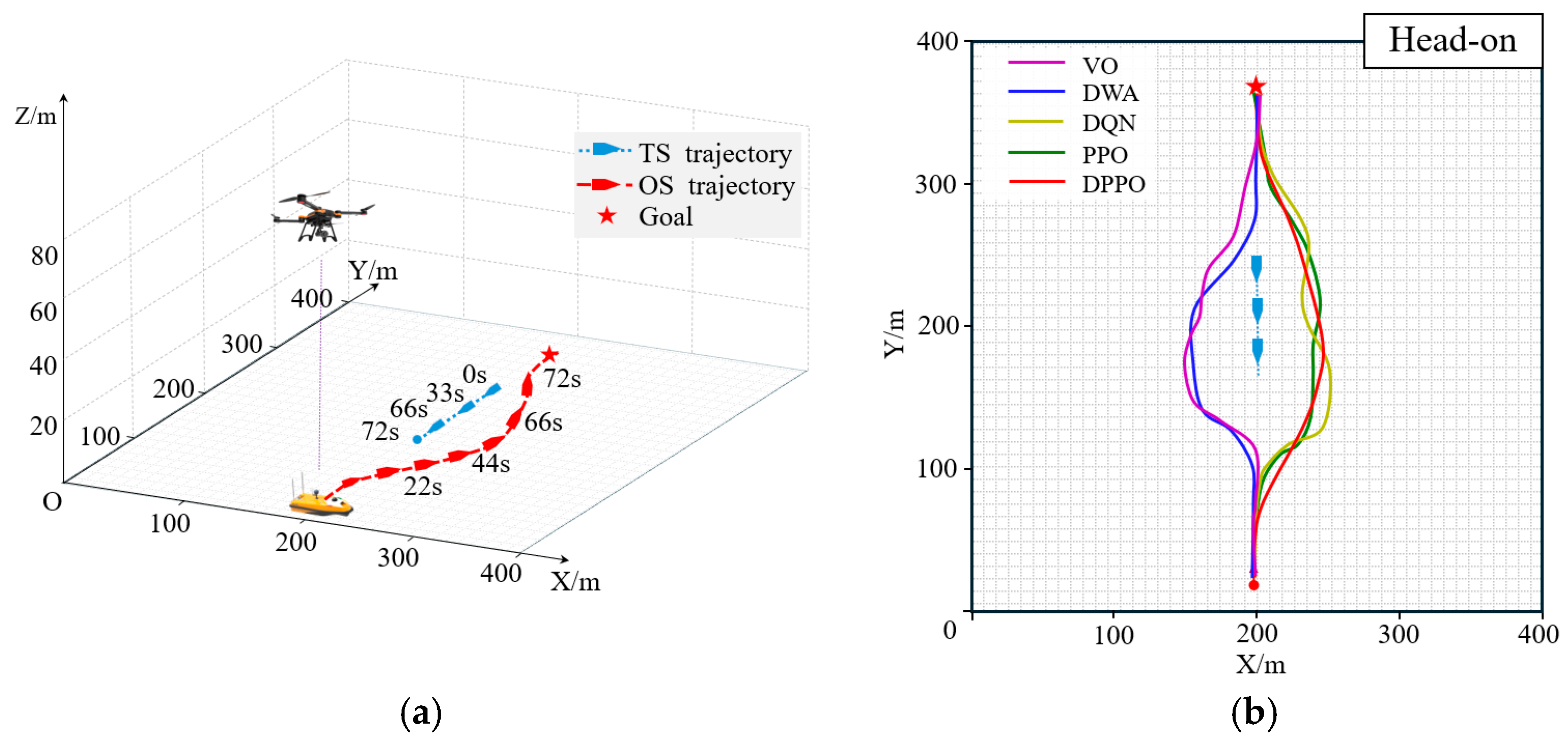
In the head-on encounter scenario, the initial navigation parameters for the target ship (TS) and the own ship (OS), which constitute a standard head-on situation, are detailed in Table 4. The collision avoidance process utilizing the DPPO algorithm is illustrated in Figure 10a. After departure, the OS proceeded toward the target direction, initiated a starboard avoidance maneuver at 17 s, and completed the primary avoidance operation around the 44-s mark. Subsequently, the OS adjusted its course by applying a port rudder and successfully reached the target position at 72 s.
A comparative analysis of the collision avoidance paths generated by the DPPO algorithm and other benchmark algorithms is presented in Figure 10b. The experimental results indicate that while all algorithms successfully guided the OS to the target position, their collision avoidance performance varied significantly. Specifically, the DWA and VO algorithms adopted a port-side avoidance strategy, which contravenes the COLREGs rules. The path generated by the DQN algorithm exhibited noticeable oscillations, and while the PPO algorithm achieved collision avoidance, its path smoothness was inferior to that of the DPPO algorithm.
To quantitatively assess the performance differences, detailed comparative metrics are provided in Table 5. In terms of path length, the DPPO algorithm demonstrates superior performance, with a length of only 376.83 m. This represents a 13.6% reduction compared to the worst-performing VO algorithm (435.99 m) and a 4.5% optimization over the PPO algorithm (394.71 m). Regarding course stability, the cumulative heading change for the DPPO algorithm is merely 1.73 rad, which is 41.6% lower than that of the DQN algorithm (2.96 rad) and 24.1% lower than that of the PPO algorithm (2.28 rad). Additionally, the DPPO algorithm consistently maintains a distance between the TS and OS that exceeds the safety threshold. The closest point of approach is recorded at 56.63 m, which meets the safety requirements for collision avoidance.
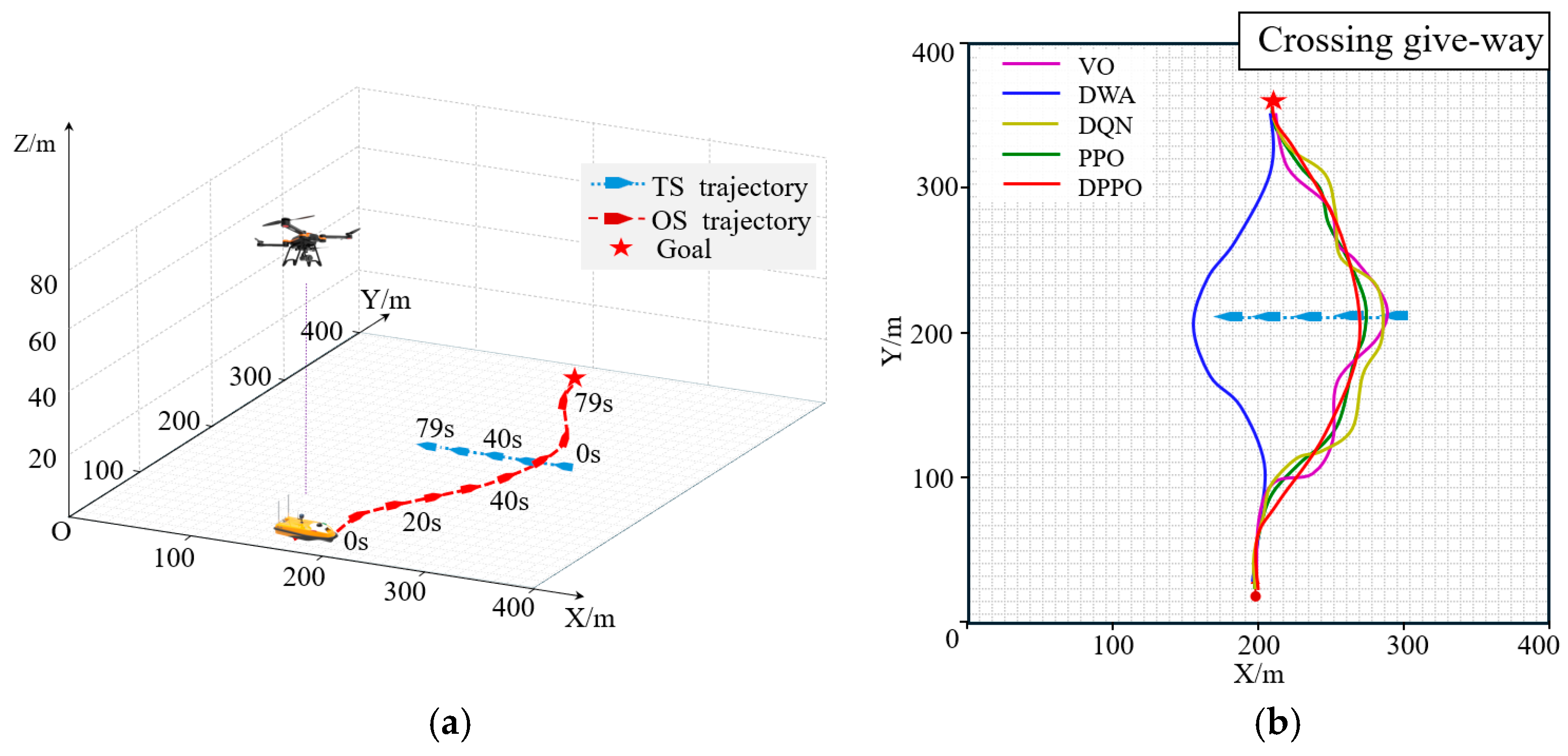
The same methodology was applied to overtaking and crossing give-way encounter scenarios. The collision avoidance results for the overtaking scenario are presented in Figure 11, with corresponding performance metrics in Table 5, while those for the crossing give-way scenario are shown in Figure 12 and Table 5. In both scenarios, the DPPO algorithm exhibited performance consistent with the head-on case, achieving the shortest path length and minimal heading changes, thereby significantly outperforming the comparative algorithms. The comprehensive experimental results across these three typical scenarios demonstrate a significant performance advantage of the proposed DPPO algorithm over the existing baseline methods. Additionally, the rudder angle variations in the DPPO algorithm in all three scenarios are shown in Figure 13, as well as the distance variation curves between the TS and OS for each scenario in Figure 14.

4.4.2. Collision Avoidance Experiment in Multi-Ship Encounter Scenarios

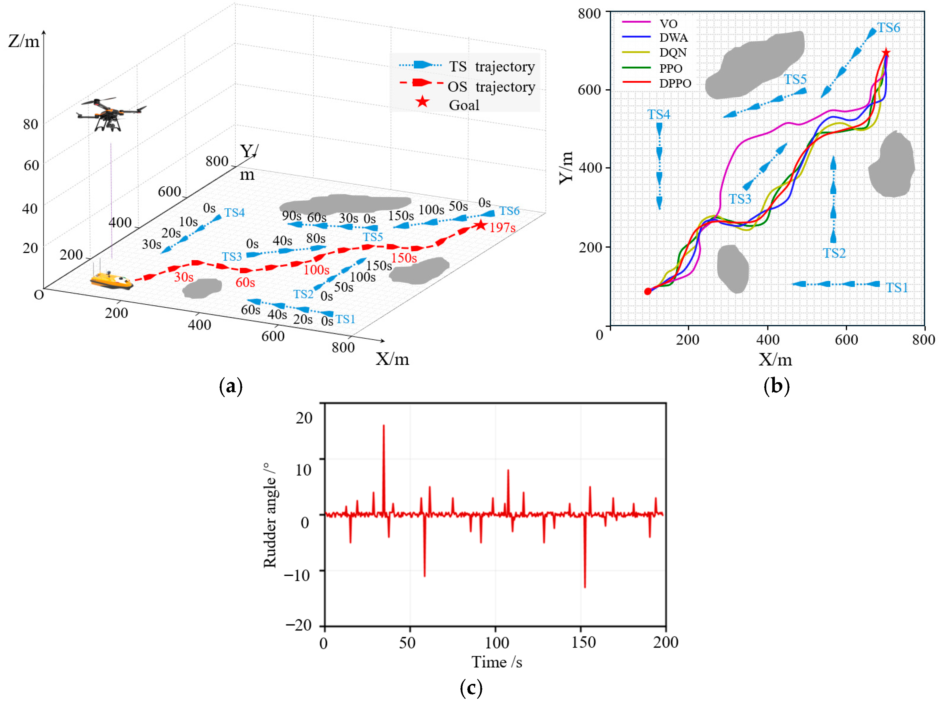
To evaluate the collision avoidance performance of the DPPO algorithm in a multi-vessel encounter scenario, a simulation environment involving six dynamic target ships (TS1–TS6) is constructed. The initial navigation parameters for each vessel are provided in Table 6. The own ship (OS) starts from position (100, 100) with the objective of reaching the target point (700, 700) while safely avoiding all obstacles.
The collision avoidance process employing the DPPO algorithm is depicted in Figure 15a. After departure, the OS successfully navigates around a static obstacle at approximately 30 s. An overtaking situation with TS3 develops around the 40-s mark, prompting the OS to execute a starboard turn to avoid TS3 before resuming its course toward the target. At approximately 140 s, the OS encounters a head-on situation with TS6 and again performs a successful collision avoidance maneuver, ultimately arriving at the target position at 197 s. Throughout the entire process, no collisions occur, and all avoidance maneuvers comply with COLREGs. The corresponding variations in rudder angle control are shown in Figure 15c.
A comparison of the collision avoidance paths generated by different algorithms in this multi-ship scenario is presented in Figure 15b, with corresponding performance metrics summarized in Table 7. In terms of path length, the trajectory planned by the DPPO algorithm is the shortest at 983.46 m, representing a reduction of 15.41% compared to the VO algorithm (1192.62 m) and 6.22% compared to the PPO algorithm (1048.73 m). Regarding cumulative heading change, the DPPO algorithm achieves a value of 3.53 rad, which is lower than those of the DWA (4.17 rad), VO (3.76 rad), and DQN (4.11 rad) algorithms, and 11.31% lower than that of the PPO algorithm (3.98 rad). Furthermore, the minimum encounter distance between the OS and any TS remains above the safety threshold at all times, satisfying navigational safety requirements. These experimental results demonstrate that the DPPO algorithm exhibits significant advantages in both global path optimality and navigation stability.

4.4.3. Collision Avoidance Experiment in Occluded Scenarios

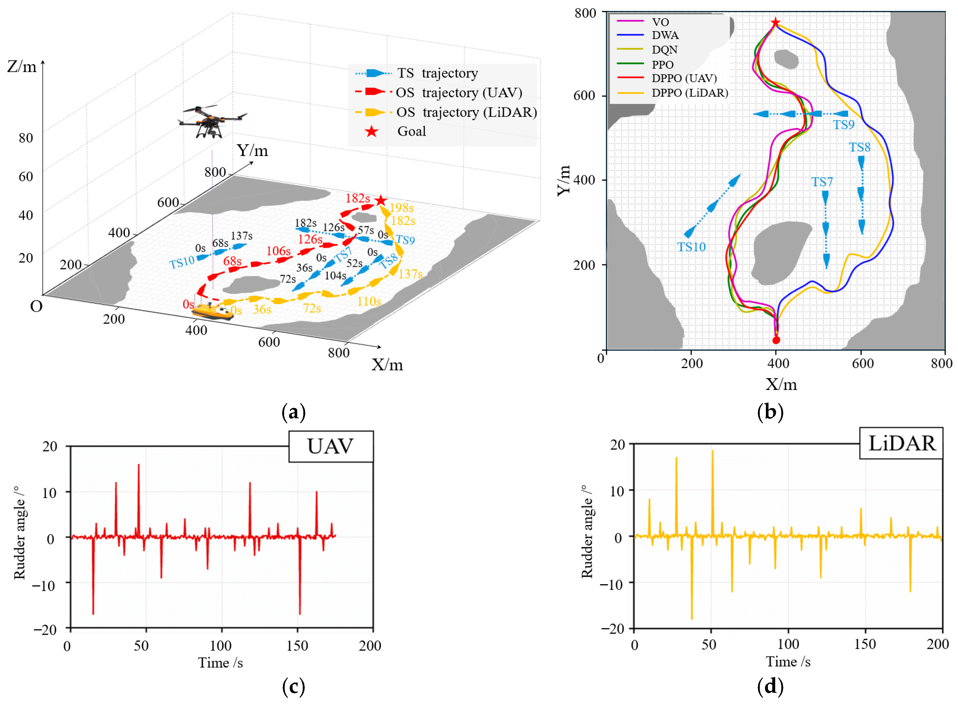
To validate the collision avoidance performance of the DPPO algorithm in occluded scenarios, a simulation environment incorporating both static and dynamic obstacles is constructed, as illustrated in Figure 16. The initial navigation parameters for the dynamic obstacle ships (TS7-TS10) are provided in Table 8. Notably, due to the inherent limitations of lidar, TS7 and TS8—positioned diagonally behind the static obstacle OBS2—cannot be effectively detected at the outset. This configuration simulates the perceptual blind spots induced by obstacle occlusion, a common challenge in real-world waterways.
For the occluded scenario, a dual comparative experiment is conducted. Firstly, the collision avoidance performance of lidar perception is compared against UAV vision-assisted perception, both implemented with the DPPO algorithm. Secondly, the performance of the DPPO algorithm was evaluated against other benchmark algorithms within the same scenario.
An analysis of the different perception schemes reveals distinct navigation strategies, as illustrated in Figure 16a. While both lidar and UAV-assisted perception successfully guided the USV to the target without collision, their approaches differed significantly. In the initial phase, the lidar-based system, unable to detect the occluded dynamic obstacles TS7 and TS8, executed a right-turn maneuver to avoid the static obstacle OBS2. This action inadvertently led to subsequent encounter situations with TS7 and TS8, thereby increasing the overall collision risk. In contrast, the UAV-assisted system, leveraging its elevated field of view, opted for a left-turn path to bypass OBS2. Although this strategy resulted in a locally longer path for static obstacle avoidance, it proactively prevented potential conflicts with the occluded dynamic obstacles from a global navigation perspective, significantly mitigating collision risks. This outcome verifies the superiority of the UAV-assisted perception scheme in occluded environments. The corresponding rudder angle variations for the two perception schemes are detailed in Figure 16c and Figure 16d, respectively.
A comparative analysis of the collision avoidance paths generated by different algorithms is presented in Figure 16b, with the corresponding performance metrics listed in Table 9. The DPPO algorithm achieved a path length of 911.46 meters and a cumulative heading change of 3.46 rad, outperforming all other algorithms in both metrics. Furthermore, the minimum distances between the USV and obstacles were consistently maintained above the safety threshold. These results demonstrate that the DPPO algorithm sustains superior navigation efficiency and control stability in occluded environments compared to the other algorithms evaluated.

4.4.4. Performance Analysis Under Environmental Disturbances

To validate the robustness of the proposed DPPO algorithm in complex marine environments, three distinct levels of wind and wave interference—simulating mild, moderate, and severe sea states—were introduced, with the experimental setup built upon the occluded scenario described in Section 4.4.3. The specific parameter configurations for these disturbances are presented in Table 10.
In the experiments, the collision avoidance performance of the DPPO algorithm is compared with that of VO, DWA, DQN, and PPO algorithms under different interference levels. The evaluation metrics include path length L path , cumulative heading change H sum , and the closest point of approach D min . Additionally, to provide a more comprehensive assessment of robustness, a success rate metric S rate is introduced, representing the proportion of collision-free trials that successfully reach the target out of 100 total runs.
The performance metrics of various algorithms under different interference levels are presented in Table 11. The results show that under mild interference, all algorithms perform well in task completion, with the DPPO algorithm maintaining advantages across all metrics. As the interference intensity increases, the DPPO algorithm exhibits the smallest reduction in success rate: it achieves a success rate of 94% under moderate interference and still retains a success rate of 86% even under severe interference. Particularly in highly disturbed environments, its performance is significantly superior to that of the PPO (72%) and DQN (58%) algorithms. Under severe interference, the VO and DWA algorithms—due to their strong reliance on fixed models and inability to adapt to dynamic disturbances—experience a sharp drop in success rates, falling to 44% and 38%, respectively. Additionally, their navigation paths become notably erratic, which leads to significant increases in both path length and cumulative heading changes. Furthermore, under all interference levels, the DPPO algorithm maintains a minimum encounter distance that exceeds the safety threshold, demonstrating excellent safety redundancy. These experimental results confirm that the proposed DPPO algorithm possesses strong robustness and adaptability when confronted with external disturbances such as wind and waves, enabling it to operate effectively even under higher sea states.

5. Conclusions

This paper proposes a collision avoidance method for USVs assisted by UAV vision. By leveraging high-altitude visual information from the UAV to construct a high-dimensional state space, the method effectively mitigates the perceptual limitations of conventional lidar in occluded environments. Furthermore, a multi-objective reward mechanism is designed by incorporating the trajectory evaluation concept of the DWA, which not only alleviates the sparse-reward problem in reinforcement learning but also guides the USV to achieve a balance among safety, path smoothness, and navigation efficiency during obstacle avoidance. Simulation results demonstrate that the proposed method outperforms several benchmark algorithms across various test scenarios in terms of key metrics such as path length and cumulative heading changes. This research not only proposes a novel approach for intelligent collision avoidance in air–sea cooperative unmanned systems but also provides valuable insights into the application of reinforcement learning in complex dynamic environments through its multi-objective reward design. The proposed method exhibits substantial theoretical significance and holds promising potential for broader practical adoption.
However, the current research primarily addresses collision avoidance decision-making for a single USV and does not investigate cooperative collision avoidance in multi-vessel interaction scenarios. Future work will focus on developing a distributed cooperative decision-making framework to extend the proposed method to multi-USV applications. Additionally, we will further investigate multi-modal perception fusion technology by integrating UAV vision with lidar and other multi-source information, thereby enhancing the system’s robustness and reliability in complex real-world maritime environments.

Author Contributions

Conceptualization, T.H. and W.G.; methodology, T.H., W.G. and C.L.; software, T.H., S.Q. and S.H.; validation, T.H., W.G. and C.L.; formal analysis, T.H. and Z.C.; investigation, C.L. and S.Q.; resources, W.G.; data curation, T.H., C.L. and S.H.; writing—original draft preparation, T.H. and Z.C.; writing—review and editing, W.G. and C.L.; visualization, S.Q., S.H. and Z.C.; supervision, W.G.; project administration, W.G.; funding acquisition, W.G. All authors have read and agreed to the published version of the manuscript.

Funding

This research was funded by the National Natural Science Foundation of China, grant number 52171342, and the Fundamental Research Funds for the Central Universities, grant number 3132023502.

Data Availability Statement

The original contributions presented in this study are included in the article. Further inquiries can be directed to the corresponding author.

Conflicts of Interest

The authors declare no conflicts of interest.

References

  1. Duan, K.; Dong, S.; Fan, Z.; Zhang, S.; Shu, Y.; Liu, M. Multimode trajectory tracking control of Unmanned Surface Vehicles based on LSTM assisted Model Predictive Control. Ocean Eng. 2025, 328, 121015. [Google Scholar] [CrossRef]
  2. Tao, Y.; Du, J.; Lewis, F.L. Integrated intelligent guidance and motion control of USVs with anticipatory collision avoidance decision-making. IEEE Trans. Intell. Transp. Syst. 2024, 25, 17810–17820. [Google Scholar] [CrossRef]
  3. Villa, J.; Aaltonen, J.; Koskinen, K.T. Path-following with lidar-based obstacle avoidance of an surface vehicle in harbor conditions. IEEE/ASME Trans. Mechatron. 2020, 25, 1812–1820. [Google Scholar] [CrossRef]
  4. Cui, Z.; Guan, W.; Zhang, X. Gated transformer-based proximal policy optimization for multiple marine autonomous surface ships collision avoidance decision-making strategy. Eng. Appl. Artif. Intell. 2025, 156, 111242. [Google Scholar] [CrossRef]
  5. Xie, Y.; Nanlal, C.; Liu, Y. Reliable LiDAR-based ship detection and tracking for Autonomous Surface Vehicles in busy maritime environments. Ocean Eng. 2024, 312, 119288. [Google Scholar] [CrossRef]
  6. Sun, S.; Lyu, H.; Gao, Z.; Yang, X. Grid map assisted radar target tracking in a detection occluded maritime environment. IEEE Trans. Instrum. Meas. 2024, 73, 8502711. [Google Scholar] [CrossRef]
  7. Li, Y.; Li, S.; Zhang, Y.; Zhang, W.; Lu, H. Dynamic route planning for a USV-UAV multi-robot system in the rendezvous task with obstacles. J. Intell. Robot. Syst. 2023, 107, 52. [Google Scholar] [CrossRef]
  8. Shao, M.; Liu, X.; Zhang, T.; Zhang, Q.; Sun, Y. Research on cooperative motion control of USV and UAV based on sliding mode self-immunity control. Expert Syst. Appl. 2025, 284, 127961. [Google Scholar] [CrossRef]
  9. Wang, Y.; Liu, W.; Liu, J.; Sun, C. Cooperative USV/UAV marine search and rescue with visual navigation and reinforcement learning based control. ISA Trans. 2023, 137, 222–235. [Google Scholar] [CrossRef]
  10. Li, W.; Ge, Y.; Guan, Z.; Gao, H.; Feng, H. NMPC-based UAV-USV cooperative tracking and landing. J. Frankl. Inst. 2023, 360, 7481–7500. [Google Scholar] [CrossRef]
  11. Zhang, H.; Fan, J.; Zhang, X.; Xu, H.; Guedes Soares, C. Unmanned Surface Vessel—Unmanned Aerial Vehicle Cooperative Path Following Based on a Predictive Line of Sight Guidance Law. J. Mar. Sci. Eng. 2024, 12, 1818. [Google Scholar] [CrossRef]
  12. Cheng, C.; Liu, D.; Du, J.; Li, Y. Research on visual perception for coordinated air–sea through a cooperative USV-UAV system. J. Mar. Sci. Eng. 2023, 11, 1978. [Google Scholar] [CrossRef]
  13. Guan, W.; Wang, K. Autonomous collision avoidance of unmanned surface vehicles based on improved A-star and dynamic window approach algorithms. IEEE Intell. Transp. Syst. Mag. 2023, 15, 36–50. [Google Scholar] [CrossRef]
  14. Zhang, W.; Shan, L.; Chang, L.; Dai, Y. SVF-RRT*: A stream-based VF-RRT* for USVs path planning considering ocean currents. IEEE Robot. Autom. Lett. 2023, 8, 2413–2420. [Google Scholar] [CrossRef]
  15. Wang, J.; Yang, L.; Cen, H.; He, Y.; Liu, Y. Dynamic obstacle avoidance control based on a novel dynamic window approach for agricultural robots. Comput. Ind. 2025, 167, 104272. [Google Scholar] [CrossRef]
  16. Zheng, M.; Zhang, K.; Han, B.; Lin, B.; Zhou, H.; Ding, S.; Zou, T.; Yang, Y. An improved VO method for collision avoidance of ships in open sea. J. Mar. Sci. Eng. 2024, 12, 402. [Google Scholar] [CrossRef]
  17. Arani, A.K.; Le, T.H.M.; Zahedi, M.; Babar, M.A. Systematic literature review on application of learning-based approaches in continuous integration. IEEE Access 2024, 12, 135419–135450. [Google Scholar] [CrossRef]
  18. Zhao, Y.; Qi, X.; Ma, Y.; Li, Z.; Malekian, R.; Sotelo, M. Path following optimization for an underactuated USV using smoothly-convergent deep reinforcement learning. IEEE Trans. Intell. Transp. Syst. 2021, 22, 6208–6220. [Google Scholar] [CrossRef]
  19. Jin, K.; Liu, Z.; Wang, J.; Wang, H. Unmanned Surface Vehicle Navigation Under Disturbances: World Model Enhanced Reinforcement Learning. IEEE/ASME Trans. Mechatron. 2025, 1–9. [Google Scholar] [CrossRef]
  20. Guan, W.; Han, H.; Cui, Z. Autonomous navigation of marine surface vessel in extreme encounter situation. J. Mar. Sci. Technol. 2024, 29, 167–180. [Google Scholar] [CrossRef]
  21. Luo, W.; Wang, X.; Han, F.; Zhou, Z.; Cai, J.; Zeng, L.; Chen, H.; Chen, J.; Zhou, X. Research on LSTM-PPO Obstacle Avoidance Algorithm and Training Environment for Unmanned Surface Vehicles. J. Mar. Sci. Eng. 2025, 13, 479. [Google Scholar] [CrossRef]
  22. Guan, W.; Luo, W.; Cui, Z. Intelligent decision-making system for multiple marine autonomous surface ships based on deep reinforcement learning. Robot. Auton. Syst. 2024, 172, 104587. [Google Scholar] [CrossRef]
  23. Chen, C.; Chen, X.Q.; Ma, F.; Zeng, X.J.; Wang, J. A knowledge-free path planning approach for smart ships based on reinforcement learning. Ocean Eng. 2019, 189, 106299. [Google Scholar] [CrossRef]
  24. Fan, Y.; Sun, Z.; Wang, G. A novel intelligent collision avoidance algorithm based on deep reinforcement learning approach for USV. Ocean Eng. 2023, 287, 115649. [Google Scholar] [CrossRef]
  25. Zhang, J.; Chen, H.; Sun, H.; Xu, H.; Yan, T. Convolutional neural network-based deep Q-network (CNN-DQN) path planning method for mobile robots. Intell. Serv. Robot. 2025, 18, 929–950. [Google Scholar] [CrossRef]
  26. Cui, Z.; Guan, W.; Zhang, X.; Zhang, G. Autonomous collision avoidance decision-making method for USV based on ATL-TD3 algorithm. Ocean Eng. 2024, 312, 119297. [Google Scholar] [CrossRef]
  27. Lou, M.; Yang, X.; Hu, J.; Zhu, Z.; Shen, H.; Xiang, Z.; Zhang, B. A Balanced Collision Avoidance Algorithm for USVs in Complex Environment: A Deep Reinforcement Learning Approach. IEEE Trans. Intell. Transp. Syst. 2024, 25, 21404–21415. [Google Scholar] [CrossRef]
  28. Xu, X.; Cai, P.; Ahmed, Z.; Yellapu, V.S.; Zhang, W. Path planning and dynamic collision avoidance algorithm under COLREGs via deep reinforcement learning. Neurocomputing 2022, 468, 181–197. [Google Scholar] [CrossRef]
  29. Xia, J.; Zhu, X.; Liu, Z.; Luo, Y.; Wu, Z.; Wu, Q. Research on collision avoidance algorithm of unmanned surface vehicle based on deep reinforcement learning. IEEE Sens. J. 2022, 23, 11262–11273. [Google Scholar] [CrossRef]
  30. Sun, P.; Yang, C.; Zhou, X.; Wang, W. Path planning for unmanned surface vehicles with strong generalization ability based on improved proximal policy optimization. Sensors 2023, 23, 8864. [Google Scholar] [CrossRef]
  31. Wu, C.; Yu, W.; Li, G.; Liao, W. Deep reinforcement learning with dynamic window approach based collision avoidance path planning for maritime autonomous surface ships. Ocean Eng. 2023, 284, 115208. [Google Scholar] [CrossRef]
  32. Zhao, W.; Zhang, Y.; Xie, Z. EPPE: An Efficient Progressive Policy Enhancement framework of deep reinforcement learning in path planning. Neurocomputing 2024, 596, 127958. [Google Scholar] [CrossRef]
  33. Hu, S.; Yuan, X.; Ni, W.; Wang, X.; Jamalipour, A. Visual-based moving target tracking with solar-powered fixed-wing UAV: A new learning-based approach. IEEE Trans. Intell. Transp. Syst. 2024, 25, 9115–9129. [Google Scholar] [CrossRef]
  34. Chen, G.; Wang, W.; Dong, J. Performance-optimize adaptive robust tracking control for USV-UAV heterogeneous systems with uncertainty. IEEE Trans. Veh. Technol. 2025, 74, 7251–7262. [Google Scholar] [CrossRef]
  35. Zhang, G.; Lin, C.; Li, J.; Zhang, W.; Zhang, X. Fault-tolerant target tracking control for the USV-UAV platform via the visual-based guidance and fault-tolerant control. Aerosp. Sci. Technol. 2025, 162, 110230. [Google Scholar] [CrossRef]
  36. Guo, C.; Zhang, Z.; Yang, Z.; Yin, Y.; Huo, Z. Deep Learning Based Compressed Sensing for Image and UWB Signal Reconstruction. IEEE Sens. J. 2025, 25, 22228–22238. [Google Scholar] [CrossRef]
  37. Zhang, L.; Peng, J.; Yi, W.; Lin, H.; Lei, L.; Song, X. A state-decomposition DDPG algorithm for UAV autonomous navigation in 3-D complex environments. IEEE Internet Things J. 2023, 11, 10778–10790. [Google Scholar] [CrossRef]
  38. Wang, R.; Miao, K.; Li, Q.; Sun, J.; Deng, H. The path planning of collision avoidance for an unmanned ship navigating in waterways based on an artificial neural network. Nonlinear Eng. 2022, 11, 680–692. [Google Scholar] [CrossRef]
Figure 1. UAV-USV cooperative coordinate system.
Jmse 13 01955 g001
Figure 2. Ship Domain Model.
Jmse 13 01955 g002
Figure 3. The model of two-ship encounter situations for clauses 13–17 of COLREGs: (a) Head-on; (b) Crossing give-way; (c) Overtaking; (d) Crossing stand-on.
Jmse 13 01955 g003
Figure 4. Two clipping situations of the PPO algorithm: (a) advantage-positive clipping; (b) advantage-negative clipping.
Jmse 13 01955 g004
Figure 5. The Neural network structure.
Jmse 13 01955 g005
Figure 6. The Algorithm flow of DPPO.
Jmse 13 01955 g006
Figure 7. Collision avoidance test results at different stages of the DPPO algorithm training process: (a) Test after 100 training episodes; (b) Test after 1000 training episodes; (c) Test after 4000 training episodes; (d) Test after 6000 training episodes.
Jmse 13 01955 g007
Figure 8. The comparison of the average reward convergence curves of the DPPO, PPO and DQN algorithm.
Jmse 13 01955 g008
Figure 9. Simulation results of UAV tracking the USV: (a) Trajectories of the UAV and USV; (b) Tracking error curve of the UAV.
Jmse 13 01955 g009
Figure 10. Collision avoidance experimental results in the head-on scenario: (a) Collision avoidance process of the DPPO algorithm; (b) Comparison of obstacle avoidance paths of different algorithms.
Jmse 13 01955 g010
Figure 11. Collision avoidance experimental results in the overtaking scenario: (a) Collision avoidance process of the DPPO algorithm; (b) Comparison of obstacle avoidance paths of different algorithms.
Jmse 13 01955 g011
Figure 12. Collision avoidance experimental results in the crossing give-way scenario: (a) Collision avoidance process of the DPPO algorithm; (b) Comparison of obstacle avoidance paths of different algorithms.
Jmse 13 01955 g012
Figure 13. Rudder angle outputs of the DPPO algorithm in different encounter scenarios: (a) Head-on; (b) Overtaking; (c) Crossing give-way.
Jmse 13 01955 g013
Figure 14. Distance variation curves between TS and OS in different encounter scenarios: (a) Head-on; (b) Overtaking; (c) Crossing give-way.
Jmse 13 01955 g014
Figure 15. Experimental results of the multi-ship encounter scenario: (a) Collision avoidance process of the DPPO algorithm; (b) Comparison of obstacle avoidance paths of different algorithms on the XY plane; (c) Rudder angle output by the DPPO algorithm.
Jmse 13 01955 g015
Figure 16. Experimental results of the occluded scenarios: (a) Collision avoidance process of the DPPO algorithm; (b) Comparison of obstacle avoidance paths of different algorithms on the XY plane; (c) Rudder angle output by the DPPO algorithm under the UAV perception scheme; (d) Rudder angle output by the DPPO algorithm under the lidar perception scheme.
Jmse 13 01955 g016
Table 1. The deep neural network parameters.
Network LayerLayer ParametersActivation FunctionOutput Dimension
Input layer--320 × 320 × 3
Conv116 kernels, 3 × 3, (stride = 2)ReLU159 × 159 × 16
Pooling12 × 2, stride = 2-79 × 79 × 16
Conv232 kernels, 3 × 3, (stride = 2)ReLU39 × 39 × 32
Pooling22 × 2, stride = 2-19 × 19 × 32
Conv364 kernels, 3 × 3, (stride = 2)ReLU17 × 17 × 64
FC164ReLU5 → 16
FC232ReLU64 → 32
Actor/Critic FC3128ReLU18,528 → 128
Actor/Critic FC464ReLU128 → 64
Actor-Output1Tanh64 → 1
Critic-Output1Linear64 → 1
Table 2. Hyperparameters of algorithm training.
Hyper-ParametersSymbolValue
Actor Network Learning Rate l r A c t o r 0.0002
Critic Network Learning Rate l r C r i t i c 0.0003
Discount Rate γ 0.97
GAE parameter λ 0.95
Clip ratio ε 0.20
Soft update τ 0.002
The entropy coefficient α 0.01
Table 3. Model parameters of the UAV and USV.
UAV-ParametersUSV-Parameters
ParametersValueParametersValue
m a 2 kglength1.5 m
k d 0.1 kg/swidth0.6 m
I a x 0.1 T s 1.5 s
I a y 0.1 K 0.2 rad/(s rad)
I a z 0.2 f ±0.1 rad/s2
Table 4. Initial navigation parameters of OS and TS in three typical collision avoidance scenarios.
Encounter SituationsShip InformationInitial OrientationVelocity (m/s)Initial Position
Head-onOS5.0(200, 10)
TS180°1.3(200, 250)
OvertakingOS5.0(200, 10)
TS1.3(200, 160)
Crossing give-wayOS5.0(200, 10)
TS−90°1.8(280, 220)
Table 5. Performance evaluation of collision avoidance algorithms in head-on, overtaking, and crossing give-way encounters.
AlgorithmHead-OnOvertakingCrossing Give-Way
L path   ( m ) / H sum   ( rad ) / D min (m) L path   ( m ) / H sum   ( rad ) / D min (m) L path   ( m ) / H sum   ( rad ) / D min (m)
VO435.96/2.61/46.25434.04/2.56/50.31445.01/2.82/46.91
DWA426.57/2.57/48.31442.52/2.74/46.14446.97/2.96/50.37
DQN429.96/2.96/50.17436.74/2.98/51.62435.23/2.68/68.92
PPO394.71/2.28/64.72416.31/2.13/65.82422.70/2.26/61.35
DPPO376.83/1.83/54.38385.47/1.86/61.78391.39/2.03/56.63
Table 6. Initial navigation parameters of dynamic obstacle ships in the multi-ship encounter scenario.
Ship InformationInitial OrientationVelocity (m/s)Initial Position
TS1−90°3.5(700, 100)
TS21.5(580, 220)
TS345°2.0(350, 350)
TS4180°7.5(100, 500)
TS5−120°2.5(500, 600)
TS6−135°1.5(700, 750)
Table 7. Performance evaluation of collision avoidance algorithms in the multi-ship encounter scenario.
Algorithm L path (m) H sum (rad) D min (m)
VO1192.623.7647.96
DWA1104.764.1753.46
DQN1123.194.1155.24
PPO1048.733.9851.49
DPPO983.463.5353.38
Table 8. Initial navigation parameters of dynamic obstacle ships in occluded scenario.
Ship InformationInitial OrientationVelocity (m/s)Initial Position
TS7180°2.5(450, 370)
TS8180°1.0(600, 460)
TS9−90°1.3(540, 540)
TS1045°1.5(200, 260)
Table 9. Performance evaluation of collision avoidance algorithms in occluded scenario.
Algorithm L path (m) H sum (rad) D min (m)
VO1062.134.2148.74
DWA1150.254.0751.46
DQN1044.143.9154.82
PPO1029.373.8253.71
DPPO911.463.4655.38
Table 10. Wind and wave disturbance parameter settings.
Disturbance LevelWind Speed (m/s)Wind Direction (°)Significant Wave Height (m)Wave Period (s)
Mild5.0450.34.0
Moderate10.0451.26.0
Severe15.0452.58.0
Table 11. Performance comparison of algorithms under different disturbance levels.
AlgorithmDisturbance Level L path (m) H sum (rad) D min (m) S rate
VOMild1065.274.2548.7494
Moderate1103.514.7646.5856
Severe1147.295.3443.2138
DWAMild1152.614.1051.4692
Moderate1189.744.8848.9262
Severe1235.885.6745.1344
DQNMild1046.333.9454.8296
Moderate1082.144.5351.2676
Severe1125.475.1248.3558
PPOMild1031.453.8553.70100
Moderate1058.924.2151.8484
Severe1093.564.6552.7772
DPPOMild915.323.4855.41100
Moderate938.673.7253.9294
Severe972.154.0553.6386
Disclaimer/Publisher’s Note: The statements, opinions and data contained in all publications are solely those of the individual author(s) and contributor(s) and not of MDPI and/or the editor(s). MDPI and/or the editor(s) disclaim responsibility for any injury to people or property resulting from any ideas, methods, instructions or products referred to in the content.