Article

Adaptive Antidisturbance Stabilization of Active Helideck Systems with Prescribed Performance via Saturation-Triggered Boundaries

1
School of Marine Electrical Engineering, Dalian Maritime University, Dalian 116026, China
2
School of Mathematics and Statistics Science, Ludong University, Yantai 264025, China
*
Author to whom correspondence should be addressed.
J. Mar. Sci. Eng. 2025, 13(10), 1949; https://doi.org/10.3390/jmse13101949
Submission received: 18 September 2025 / Revised: 4 October 2025 / Accepted: 10 October 2025 / Published: 11 October 2025
(This article belongs to the Special Issue Control and Optimization of Ship Propulsion System)

Abstract

Active helidecks systems (AHS) provide an effective solution scheme for the safe landing of helicopters on ships. This article proposes a novel adaptive antidisturbance prescribed performance control law of AHS subject to input saturation, ship motion-induced external disturbances. Specifically, we develop novel saturation-triggered boundaries to guarantee prescribed tracking error constraints under input saturation. This effectively addresses the control singularity issue inherent in traditional prescribed performance control, which occurs when input saturation causes the control error to exceed prescribed constraint boundaries. Subsequently, we design a continuous auxiliary dynamic system to further mitigate the effects of input saturation. Furthermore, leveraging the internal model principle and the periodic nature of ship motion, external disturbances are treated as the outputs of a linear exosystem with known structure but unknown parameters. These unknown parameters are then estimated using adaptive techniques, enabling asymptotic estimation of external disturbances. Building upon these developments and employing the backstepping design tool, we achieve adaptive antidisturbance stabilization of AHS. Both theoretical analysis and comparative simulations validate the proposed control law.

1. Introduction

The safe landing of helicopters on ship decks, especially amid adverse weather conditions and rough seas, remains a critical and challenging operation in maritime aviation. The limited space and dynamic motion of the ship pose significant risks, including helicopter rollover and catastrophic accidents [1,2,3,4]. To mitigate these risks, Active Helideck Systems (AHSs) have emerged as a promising solution. By utilizing a controlled motion platform isolated from the ship’s primary structure, an AHS can actively compensate for the ship’s motion, delivering a stabilized landing surface for helicopters and markedly enhancing operational safety and availability.
In [5], a three-degree-of-freedom (DOF) movable mechanism was developed for active vibration reduction during helicopter landing that was capable of compensating for ship roll, sway, and heave motions. This work was extended in [6] to a four-DOF mechanism that additionally accounts for pitch motion. However, neither study presented the design of active motion compensation controllers. In contrast, Reference [7] designed a Stewart-platform-based AHS and employed proportional-derivative controllers with position feedback to coordinately regulate three electric cylinders, thereby stabilizing the deck against roll, pitch, and heave motions in inertial space. Meanwhile, Reference [8] implemented a four-hydraulic-cylinder AHS using the fuzzy proportional–integral–derivative (PID) algorithm introduced in [9] to counteract ship-induced roll, pitch, and heave. Both [7,8] provided experimental validation of the proposed AHS designs and their associated control strategies.
Research on control design for AHSs specifically tailored for helicopter landing scenarios remains relatively limited. Most existing studies focus on ship motion compensation using stabilized platforms in general settings, where researchers have conducted significant work that can be broadly categorized into joint-space control based on kinematics, joint-space control based on dynamics, and task-space control methods. In [10], a triple-loop control strategy for the actuators of a ship-mounted Stewart platform was developed by computing the desired displacement of each actuator through kinematic inversion, where active disturbance rejection control, sliding mode control, and internal model control were employed to enhance robustness. Reference [11] combined an extended state observer with sliding mode control to design a control law for the hydraulic servo system of a marine stabilized platform. Reference [12] designed an actuator control law for a ship-borne hydraulic parallel platform using the model predictive control and a sliding mode based load disturbance observer. Reference [13] developed a PID-based control law for a parallel stabilized platform in marine operations, with control parameters optimized via the particle-swarm-optimization-based backpropagation neural network. In comparison, joint-space control methods based on dynamics offer stronger capabilities in handling model uncertainties and load perturbations in stabilized platforms. Reference [14] proposed an adaptive robust dual-loop control scheme for ship-mounted Stewart platforms using backstepping and adaptive techniques, incorporating a velocity feedforward compensator to decouple motion disturbances from the base platform. Reference [15] designed a stabilization control law for a ship-borne Stewart platform by integrating an adaptive estimation method using time-delay estimation and Kalman filtering to estimate time-varying gravity, combined with nonsingular terminal sliding mode control. Reference [16] developed a stabilization control law combining a linear extended state observer (LESO) and linear quadratic regulator, where the LESO was designed to enhance robustness by estimating and compensating for overall disturbances, including model dynamics and coupling effects. Task-space control methods, in contrast, directly utilize pose error feedback of the supporting surface of the stabilized platform. By considering the dynamic characteristics of the platform as an integrated system, this method facilitates unified handling of all factors contributing to control error, such as ship motion, load variation, and external disturbances. Reference [17] proposed a stabilization control scheme for a three-DOF parallel vessel-borne platform subject to dynamic uncertainties and unknown disturbances using the super-twisting method, where an adaptive super-twisting extended state observer was designed to estimate the total disturbances.
From a practical standpoint, another critical issue in platform stabilization control is input saturation, which can severely degrade control performance and even lead to instability. In [17,18], input saturation in Stewart platforms was addressed by formulating it as inequality constraint within a stabilization optimization problem that was solved via model predictive control (MPC). Meanwhile, studies such as [19,20,21] employed auxiliary dynamic systems to mitigate the adverse effects of saturation. However, the MPC approach is highly dependent on an accurate platform model, and the auxiliary systems introduced in the latter works inevitably introduce additional control errors. Additionally, the auxiliary dynamic systems in [19,20] exhibit discontinuities that fail to remain effective upon the recurrence of input saturation.
In practical applications, ensuring prescribed transient and steady-state control performance is of significant importance. The prescribed performance control (PPC) method, pioneered by Bechlioulis and Rovithakis [22], enforces such performance guarantees through an exponentially decaying prescribed performance function (PPF) and a logarithmic error transformation. This approach has recently been extended to the stabilization control of seeker stabilized platforms [23]. It is noteworthy, however, that in the conventional PPC framework, control input saturation that drives the tracking error beyond the prescribed constraints can lead to singularity issues.
Therefore, a significant research gap remains in developing a stabilization control scheme for AHSs that can simultaneously (a) guarantee prescribed transient and steady-state performance, (b) effectively handle recurrent input saturation without inducing controller singularity or instability, and (c) achieve asymptotic rejection of periodic ship-motion-induced disturbances. Bridging this gap is crucial for enhancing the safety and energy efficiency of shipborne helicopter landing operations.
Motivated by the above discussions, this article proposes a novel adaptive antidisturbance control scheme for the stabilization of an AHS with prescribed performance under input saturation. The main contributions of this article are summarized below.
(1)
We incorporate novel saturation-triggered boundaries into the PPC framework. This mechanism allows the prescribed performance boundaries to be dynamically adjusted upon the detection of input saturation, which effectively prevents the control error from transgressing into the singular region and thus resolves the control singularity problem inherent in conventional PPC.
(2)
An auxiliary dynamic system (ADS) is designed to further mitigate the adverse effects of input saturation. By incorporating a novel piecewise continuous function vector and robustifying terms, the proposed ADS is engineered to remain functional even under recurrent saturation conditions and ensures asymptotic stability of the stabilization errors, thereby overcoming the limitations of discontinuity and ineffectiveness in existing ADS approaches.
(3)
Leveraging the internal model principle, we model the complex ship-motion-induced disturbances as outputs of a linear exosystem with known dynamics but unknown parameters. These parameters are then accurately estimated online via adaptive techniques, enabling asymptotic disturbance estimation and rejection.
The remainder of this paper is organized as follows. Section 2 formulates the problem and presents preliminary knowledge. The main controller design and stability analysis are detailed in Section 3. Section 4 presents simulation results to validate the proposed approach. Finally, Section 5 concludes the paper.

2. Materials and Methods

Usually, ships equip dynamic positioning systems that can actively suppress the motions of the ship in surge, sway, and yaw [24]. Therefore, only the other 3-DOF ship motions in roll, pitch, and heave should be compensated for. In this article, we consider a 3-DOF parallel AHS. We define two reference frames, as indicated in Figure 1. X e Y e Z e is the north–east–down reference frame, where the origin O e can be selected as any point on the surface of the Earth and the axes X e , Y e , and Z e point to the north, the east, and the center of the earth, respectively. The north–east–down frame can be regarded as an inertial coordinate frame. X b Y b Z b is the body-fixed reference frame, where the origin O b is located at the mass center of the supporting surface and the axes X b , Y b , and Z b point to the fore, the starboard, and the bottom of the ship, respectively.
The motion mathematical model of the 3-DOF parallel AHS can be described by the following dynamic equation [25,26]:
M ( q ) q ¨ + C ( q , q ˙ ) q ˙ + G = τ + τ s
where q = [ z , φ , θ ] T represents the position and orientation vector of the supporting surface of the AHS in the north–east–down frame, consisting of the heave displacement z, the roll angle φ , and the pitch angle θ ; τ = [ τ 1 , τ 2 , τ 3 ] T represents the control input vector of the AHS, consisting of the heave force F z , the roll moment M φ , and the pitch moment M θ ; τ s = [ τ s , 1 , τ s , 2 , τ s , 3 ] T represents the disturbance force and moment vector acting on the AHS due to ship motions; M ( q ) is the inertial matrix; C ( q , q ˙ ) is the Coriolis-centripetal matrix; G is the gravity vector; the matrix M ( q ) 2 C ( q , q ˙ ) is skew-symmetric. The detailed expressions of M ( q ) , C ( q , q ˙ ) and G are given in Appendix A. The control input saturation nonlinearities of τ i ( i = 1 , 2 , 3 ) is described as
τ i = τ max , i if τ c , i > τ max , i τ c , i if τ min , i τ c , i τ max , i τ min , i if τ c , i < τ min , i ( i = 1 , 2 , 3 )
where τ min , i and τ max , i are the saturation limits and τ c , i is the command control input. We denote τ c = [ τ c , 1 , τ c , 2 , τ c , 3 ] as the command control input vector and Δ τ = τ τ c as the inconsistency between the actual and the command control inputs.
We denote q d = [ z d , φ d , θ d ] T as the constant desired vector of the position and orientation of the platform, and e = q q d = [ e 1 , e 2 , e 3 ] T as the stabilization error of the AHS. In this paper, we focus on the stabilization control performance of the platform and aim to ensure that the stabilization errors e i ( i = 1 , 2 , 3 ) meet the prescribed transient and steady-state performance requirements. Based on the concept of prescribed performance control [22], the stabilization errors must meet the following constraints:
ρ l , i < e i < ρ u , i ( i = 1 , 2 , 3 )
where ρ l , i and ρ u , i are time-varying functions referred to as saturation-triggered boundaries, which will be designed later.
The control objective of this article is to propose an adaptive antidisturbance prescribed performance control law of AHSs subject to input saturation and ship-motion-induced external disturbances, so that the position and orientation vector q of the supporting surface is maintained at the desired constant value q d , while the errors e i ( i = 1 , 2 , 3 ) meet the prescribed performance constraints (3).

3. Main Results

3.1. Saturation-Triggered Boundaries

In the conventional PPC [22], an example performance function is ρ = ( ρ 0 ρ ) e μ t + ρ , with ρ 0 , ρ , μ being appropriately defined positive constants. The corresponding constraint for the error e i is
ρ i < e i < ρ i
where ρ i is a performance function associated with e i . In addition, the following error transformation function are given:
z 1 , i = 1 2 ln e i + ρ l , i ρ u , i e i
where z 1 , i is the transformed variable, and its boundedness is enough to ensure the satisfaction of error constraint (4).
It should be noted that although the PPC typically ensures error constraint satisfaction under normal operation, input saturation (e.g., triggered by abrupt disturbances or overly stringent steady-state constraints of the performance function) may cause constraint violation (4). According to (5), this leads to a controller singularity issue, and the error e i cannot be recovered within the constraint boundaries and may even diverge.
To bridge this critical gap, we develop the saturation-triggered boundaries
ρ l , i ( t ) = ρ l , 0 i ρ l , , i exp μ l , i t ρ l , , i ξ l , α i , i
ρ u , i ( t ) = ρ u , 0 , i ρ u , , j exp μ u , i t + ρ u , , i + ξ 1 , β i , i
where μ l , i > 0 and μ u , i > 0 denote the convergence rate of ρ l , i and ρ u , i , respectively; ρ l , , i > 0 and ρ u , , i > 0 are the steady-state values of ρ l , i and ρ u , i ; ρ l , 0 , i > 0 and ρ u , 0 , i > 0 are the steady-state values of ρ l , i and ρ u , i , respectively, when input saturation does not occur; and ξ 1 , i , i ( i = α i , β i ) is a saturation-triggered variable generated by the following second-order filter
ξ ˙ 1 , i , i = ω i ξ 2 , i , i , ξ 1 , i , i ( 0 ) = τ c , i ( 0 ) τ ( 0 ) ξ ˙ 2 , i , i = ζ j ω i ξ 2 , i , i ω i i ξ 1 , i , i | Δ τ i | , ξ 2 , i , i 0 = 0
where ω i > 0 and ζ i > 0 are positive design constants and α i and β i are so-called direction-aware coefficients which are defined as
α i = 1 + sign ( τ c , i τ i ) 2
β i = 1 + sign ( τ i τ c , i ) 2
Remark 1.
In the proposed saturation-triggered boundaries (6) and (7), the terms ξ l , i , i resolve the controller singularity. Here, ξ l , i , i is the filtered saturation deviation Δ τ i . When saturation occurs ( Δ τ i 0 ), ξ l , i , i triggers boundary relaxation driven by saturation. Crucially, a second-order filter (matching the system order) is adopted. By tuning ( ω i , ζ i ) to align with the system bandwidth, an appropriate relaxation magnitude is achieved. The direction-aware coefficients α i / β i enable directional relaxation:
  • Under positive saturation ( τ c , i τ i > 0 ), relax ρ l , i while fixing ρ u , i ;
  • Under negative saturation ( τ c , i τ i < 0 ), relax ρ u , i while fixing ρ l , i ;
This directional relaxation mechanism together with the saturation-triggered variable ξ l , i , i constitute the key innovation and primary distinction compared with valuable prior works [27,28,29].
According to (5), we make an error transformation
z 1 , i = 1 2 ln e i ρ l , i ( t ) ρ u , i ( t ) e i
which transforms the problem of preserving the prescribed performance constraint (3) for tracking error e i into an equivalent boundedness problem for the transformed variable z 1 , i .
For the purpose of subsequent control design development, we present the time derivative of the transformed variable z 1 , i
z ˙ 1 , i = 1 2 ln e i ρ l , i ( t ) ρ u , i ( t ) e i = 1 2 d d t ln ( e i ρ l , i ( t ) ) ln ( ρ u , i ( t ) e i ) = 1 2 e ˙ i ρ ˙ l , i ( t ) e i ρ l , i ( t ) ρ ˙ u , i ( t ) e ˙ i ρ u , i ( t ) e i = P i e ˙ i Q i
where P i = ρ u , i ( t ) ρ l , i ( t ) 2 ( e i ρ l , i ( t ) ) ( ρ u , i ( t ) e i ) > 0 and Q i = 1 2 ρ ˙ l , i ( t ) e i ρ l , i ( t ) + ρ ˙ u , i ( t ) ρ u , i ( t ) e i .

3.2. Adaptive Antidisturbance Prescribed Performance Control

In this subsection, we propose an adaptive antidisturbance prescribed performance control law for the AHS using backstepping design procedures [30]. The control design consists of the following two steps.
Step 1: Define the vector z 1 = [ z 1 , 1 , z 1 , 2 , z 1 , 3 ] T . Taking the time derivative of z 1 and according to (12) and e = q q d , we have
z ˙ 1 = P q ˙ Q
where P = d i a g ( P 1 , P 2 , P 3 ) and Q = [ Q 1 , Q 2 , Q 3 ] T .
By considering q ˙ as a virtual control, an intermediate control vector χ 3 is synthesized to stabilize the subsystem (13)
χ = K 1 P 1 z 1 + Q
where K 1 is a positive definite design matrix.
Step 2: Define the error vector z 2 as
z 2 = q ˙ χ
Select a Lyapunov function candidate
V 1 = 1 2 z 1 T z 1 + 1 2 z 2 T M ( q ) z 2
Taking the time derivative of V according to (1) and (13)–(15), Δ τ = τ τ c , and that the truth that the matrix M ( q ) 2 C ( q ˙ , q ) is skew-symmetric, one gets
V ˙ = z 1 T z ˙ 1 + z 2 T M ( q ) z ˙ 2 + 1 2 z 2 T M ˙ ( q ) z 2 = z 1 T [ P ( z 2 + χ ) Q ] + z 2 T τ + τ s C ( q , q ˙ ) q ˙ G M ( q ) χ ˙ + 1 2 z 2 T M ˙ ( q ) z 2 = z 1 T K 1 z 1 + z 1 T P z 2 + z 2 T τ + τ s C ( q , q ˙ ) ( z 2 + χ ) G M ( q ) χ ˙ + 1 2 z 2 T M ˙ ( q ) z 2 = z 1 T K 1 z 1 + z 1 T P z 2 + z 2 T τ c + Δ τ + τ s C ( q , q ˙ ) χ G M ( q ) χ ˙
Then, we design an ADS to overcome Δ τ as
κ ˙ = K k κ + Δ τ η s , κ κ a K k κ h | z 2 T Δ τ | + 1 2 Δ τ T Δ τ κ 2 κ + Δ τ η s , κ a < κ < κ b K k κ | z 2 T Δ τ | + 1 2 Δ τ T Δ τ κ 2 κ + Δ τ η s , κ κ b
with
η s = γ ^ s 2 κ γ ^ s κ + δ s
γ ^ ˙ s = λ s , 1 Proj ( κ , γ ^ s )
δ ˙ s = λ s , 2 δ s , δ s ( 0 ) > 0
where κ 3 is the state vector, η s is a robustifying term to cancel the undesired term κ T Δ τ that emerges in the later stability analysis when | | κ | | < κ b , h = 3 K κ a κ b κ a 2 2 K κ a κ b κ a 3 , K κ = K κ T 3 × 3 is a positive definite design matrix, 0 < κ a < κ b are arbitrarily small design constants, γ ^ s is the estimate of γ s with γ s = sup K < κ b Δ τ , and λ s , 1 and λ s , 2 are positive design constants.
The disturbance τ s is the function of the motions of the ship, which are periodic, thus each component of τ s can be decomposed into the superposition of a series of sinusoidal signals. (Assume that the number of the sinusoidal signals is k). Leveraging the internal model principle [31], the disturbance τ s can be treated as the output of a linear exosystem of the known order but with unknown parameters as follows.
ζ ˙ = Γ ζ
τ s = H ζ
where ζ R 2 k is the state vector, Γ R 2 k × 2 k is the system matrix, and H R 3 × 2 k is the output matrix. Both Γ and H are unknown. All eigenvalues of Γ are purely imaginary, and the pair ( Γ , H ) is observable.
Next, define the matrices Ω R 2 k × 2 k , L R 2 κ × 3 , and F R 2 κ × 2 κ , where Ω is Hurwitz, the pair ( Ω , L ) is controllable, and F is the solution of the following equation
F Γ Ω F = L H
Define the vector x = F ζ R 2 k ; according to (24), the exosystem can be represented as
x ˙ = Ω x + L τ s ,
τ s = Θ T x
where Θ = [ Θ 1 , Θ 2 , Θ 3 ] T = ( H F 1 ) T R 2 k × 3 is an unknown constant matrix.
Further, we construct the observer to estimate x
x ^ ˙ = Ω x ^ + L ( M ( q ) q ¨ + C ( q , q ˙ ) q ˙ + G τ )
According to (1), (25), and (27), we have
x ˜ ˙ = x ^ ˙ x ˙ = Ω x ^ + L ( M ( q ) q ¨ + C ( q , q ˙ ) q ˙ + G τ ) Ω x L τ s = Ω x ^ + L τ s Ω x L τ s = Ω x ˜
where x ˜ = x ^ x can exponentially attenuate since Ω is Hurwitz. Therefore, from (26), we have
τ s = Θ T x ^ Θ T x ˜
Remark 2.
It can be observed that the disturbance τ s is expressed as a parametric equation with an unknown parameter matrix Θ. Since x ˜ is exponentially convergent, an estimate of the disturbance τ s , denoted as τ ^ s = Θ ^ T x ^ , can be obtained by designing an adaptive law for Θ. This leads to the so-called adaptive disturbance estimator (ADE). As a result, we can achieve adaptive antidisturbance control by incorporating τ ^ s into the control law in a feedforward manner.
Based on the above, we propose the adaptive antidisturbance prescribed performance control law of the AHS as
τ c = P z 1 K 2 z 2 + K 3 κ + C ( q , q ˙ ) χ + G + M ( q ) χ ˙ f Θ ^ T x ^ η r
where K 2 = K 2 T R 3 × 3 and K 3 = K 3 T R 3 × 3 are positive definite design matrices. Here, χ ˙ f is obtained by filtering χ using some differentiators [28,32], since χ ˙ is not easy to compute directly. This process, however, introduces a filtering error χ e , which is bounded by χ e < χ ¯ e . Therefore, another robustifying term, η r , is designed to compensate for this error and other undesirable residual terms arising in the stability analysis as follows
η r = γ ^ r 2 z 2 γ ^ r z 2 + δ r
with
γ ^ ˙ r = λ r , 1 Proj ( z 2 , γ ^ r )
δ ˙ r = λ r , 2 δ r , δ r ( 0 ) > 0
where γ ^ r is the estimate of γ r with γ r = γ s + M ( q ) χ ¯ e , and λ r , 1 and λ r , 2 are positive design constants.
The adaptive law of Θ is designed as
Θ ^ ˙ i = K 0 , i Proj ( z 2 , x ^ , Θ ^ i ) , i = 1 , 2 , 3
where K 0 , i = K 0 , i T R 2 k × 2 k is a positive definite design matrix.
Remark 3.
Unlike existing ADS approaches [19,20] that exhibit a discontinuous nature that limits their effectiveness under recurrent saturation and introduces additional errors, our designed ADS maintains functionality during repeated saturation and achieves asymptotic stability with the help of the novel piecewise continuous function vector and robustifying terms η s and η r .

3.3. Stability Analysis

Theorem 1.
Consider the closed-loop stabilizing control system consisting of the AHS (1), the intermediate control vector (14), the ADS (18) with (19)–(21), the observer (27), and adaptive antidisturbance prescribed performance control law (30) with (31)–(34). The position and orientation vector q of the AHS is stabilized at the desired value q d , with the stabilization errors e i ( i = 1 , 2 , 3 ) meeting the prescribed performance (3); all signals in the closed-loop stabilizing control system are uniformly bounded.
Proof. 
Select the augmented Lyapunov function candidate
V a = V + 1 2 κ T κ + 1 2 i = 1 3 Θ ˜ i T K 0 , i 1 Θ ˜ i + x ˜ T P x ˜ + γ ˜ s 2 2 λ s , 1 + δ s λ s , 2 + γ ˜ r 2 2 λ r , 1 + δ r λ r , 2
where Θ ˜ i = Θ ^ i Θ i , γ ˜ s = γ ^ s γ s , and γ ˜ r = γ ^ r γ r , and P is the solution of
Ω T P + P Ω = Θ Θ T
Taking the time derivative of V a yields
V ˙ a = V ˙ + k T k ˙ + i = 1 3 Θ ˜ i T K 0 , i 1 Θ ^ ˙ i + x ˜ T P x ˜ ˙ + x ˜ ˙ T P x ˜ + γ ˜ s γ ^ ˙ s λ s , 1 + δ ˙ s λ s , 2 + γ ˜ r γ ^ ˙ r λ r , 1 + δ ˙ r λ r , 2
Substituting (29)–(34) and (36) into (17), and according to the property of the projection operator (see the Definition 1 in [33]), yields
V ˙ a z 1 T K 1 z 1 z 2 T K 2 z 2 + z 2 T K 3 κ + M ( q ) χ ˙ f M ( q ) χ ˙ f θ ^ T x ^ η r + Θ T x ^ Θ T x ˜ + Δ τ + κ T κ ˙ + i = 1 3 Θ ˜ i T Proj z 2 , i x ˜ , θ ^ i + x ˜ ˙ T P x ˜ + x ˜ T P x ˜ ˙ + γ ˜ s κ δ s + γ ˜ r z 2 δ r z 1 T K 1 z 1 z 2 T K 2 z 2 + z 2 T K 3 κ θ ˜ T x ^ η r Θ T x ˜ + z 2 Δ τ + z 2 M ( q ) χ ¯ e + κ T κ ˙ + i = 1 3 Θ ˜ i T Proj z 2 , i x ˜ , θ ^ i + x ˜ ˙ T P x ˜ + x ˜ T P x ˜ ˙ + γ ^ s κ γ s κ δ s + γ ^ r z 2 γ r z 2 δ r z 1 T K 1 z 1 z 2 T K 2 z 2 + z 2 T K 3 κ z 2 T γ ^ s 2 z 2 γ ^ r z 2 + δ r + z 2 T Δ τ + z 2 M ( q ) χ ¯ e z 2 T Θ T x ˜ + κ T κ ˙ + x ˜ ˜ T P x ˜ + x ˜ T P x ˜ + γ ^ s κ γ s κ δ s + γ ^ r z 2 γ r z 2 δ r z 1 T K 1 z 1 z 2 T K 2 z 2 + z 2 T K 3 κ + z 2 T Δ τ + z 2 M ( q ) χ ¯ e + 1 4 z 2 2 + Θ T x ˜ 2 + κ T κ ˙ x ˜ T Θ Θ T x ˜ + γ ^ s κ γ s κ δ s γ r z 2 δ r 1 γ ^ r z 2 γ ^ r z 2 + δ r z 1 T K 1 z 1 z 2 T K 2 z 2 + 1 4 z 2 2 + z 2 T K 3 κ + z 2 T Δ τ + z 2 M ( q ) χ ¯ e + κ T κ ˙ + γ ^ s κ γ s κ δ s γ r z 2
(1) When | | κ | | κ b , according to (18) and Young’s inequality, we have
κ T κ ˙ = κ T K κ κ z 2 T Δ τ 1 2 Δ τ T Δ τ + κ T Δ τ γ ^ s 2 κ T κ γ ^ s | | κ | | + δ s κ T K κ κ z 2 T Δ τ + 1 2 κ T κ γ ^ s 2 κ T κ γ ^ s | | κ | | + δ s
Substituting (39) into (38), using Young’s inequality, and considering that the term | | z 2 | | | | M ( q ) | | in (30) can be bounded by | | z 2 | | γ r , we can obtain
V ˙ a z 1 T K 1 z 1 z 2 T K 2 z 2 + 1 4 z 2 2 + z 2 T K 3 κ + | z 2 T Δ x | κ T K κ κ | z 2 T Δ τ | + 1 2 κ T κ γ ^ s 2 κ T κ γ ^ s κ + δ s + γ ^ s κ γ s κ δ s z 1 T K 1 z 1 z 2 T K 2 z 2 + 1 4 z 2 2 + 1 2 z 2 T z 2 + 1 2 κ T K 3 K 3 κ κ T K κ κ + 1 2 κ T κ δ s 1 γ ^ s κ γ ^ s κ + δ s γ s κ z 1 T K 1 z 1 z 2 T K 2 3 4 I 6 × 6 z 2 κ T K κ 1 2 K 3 K 3 1 2 I 6 × 6 κ
(2) When | | κ | | < κ b , according to (18), we have
κ T κ ˙ κ T K κ κ | τ 2 T Δ τ | 1 2 Δ τ T Δ τ + γ s κ γ ^ s 2 κ T κ γ ^ s κ + δ s κ T K κ κ + γ s κ γ ^ s 2 κ T κ γ ^ s κ + δ s
where 0 < 1 .
Note that | | Δ τ | | is bounded under this case; thus, the term | | z 2 | | | | M ( q ) | | χ ¯ e + | z 2 T Δ τ | in (30) can be bounded by | | z 2 | | γ r . According to this and substituting (41) into (38) yields
V ˙ a z 1 T K 1 z 1 z 2 T K 2 z 2 + 1 4 z 2 2 + z 2 T K 3 κ κ T K κ κ + γ s κ γ ^ s 2 κ T κ γ ^ s κ + δ s + γ ^ s κ γ s κ δ s z 1 T K 1 z 1 z 2 T K 2 z 2 + 1 4 z 2 2 + 1 2 z 2 T z 2 + 1 2 κ T K 3 K 3 κ κ T K κ κ δ s 1 γ ^ s κ γ ^ s κ + δ s z 1 T K 1 z 1 z 2 T K 2 3 4 I 6 × 6 z 2 κ T K κ 1 2 K 3 K 3 κ
Synthesizing (40) and (42), we have
V ˙ a C z 1 T z 1 + z 2 T z 2 + κ T κ
where C = min { λ min ( K 1 ) , λ min ( K 2 ) 3 4 , λ min ( K k 1 2 K 3 K 3 ) 1 2 } with K 2 , K k and K 3 satisfying
λ min ( K 2 ) > 1 2
λ min K k 1 2 K 3 K 3 > 1 2
In the light of (31) and (35), the boundedness of Θ , x , γ s , and γ r and the LaSalle–Yoshizawa theorem, we conclude that the closed-loop stabilizing control system is stable and that z 1 , z 2 , k , Θ ˜ , x ˜ , γ ˜ s , γ ˜ r , δ s , and δ r are uniformly bounded. Combining this with (11), (14), and (30), the boundedness of the intermediate control vector χ and control law τ c are guaranteed. Moreover, the stabilization errors e i ( i = 1 , 2 , 3 ) meeting the prescribed performance (3) then follow from the boundedness of z 1 . Thus, Theorem 1 has been proved. □

4. Simulation

To verify the effectiveness of our proposed adaptive antidisturbance prescribed performance control law of the AHS, simulations are carried out on a three-DOF parallel test platform, whose mathematical model parameters are presented in Table 1 [25].
The supply ship from the Simulink toolbox Marine Systems Simulator (MSS) [34] is selected as the ship bearing the test platform, whose main parameters are listed in Table 2.
Simulations are carried out in two different sea states; the wave parameter values are listed in Table 3.
The unmanned shipborne helicopter’s (AR-500B [35]) main parameters are listed in Table 4. The unmanned shipborne helicopter enters the soft landing stage at 6 s and generates a landing load force d L , which is approximately given according to the landing load analysis of helicopters in [36]. We denote the total disturbance vector consisting of ship-motion-induced disturbances and load force as f = [ f 1 , f 2 , f 3 ] T = [ τ s , 1 + d L , τ s , 2 , τ s , 3 ] T
d L = 1 0.4 s 2 + 0.5 s + 1 d ¯ L
where d ¯ L = 0 , t < 25 4900 tanh ( 10 ( t 25 ) ) t 25 .
The origin O e of the north–east–down reference frame O e X e Y e Z e is chosen as the desired position and orientation, that is q d = [ 0 m , 0 rad , 0 rad ] T . The initial states are taken as q ( 0 ) = [ 1 m , 0.5 rad , 0.5 rad ] T and q ˙ ( 0 ) = [ 0 m / s , 0 rad / s , 0 rad / s ] T . The design parameters are given in Table 5.
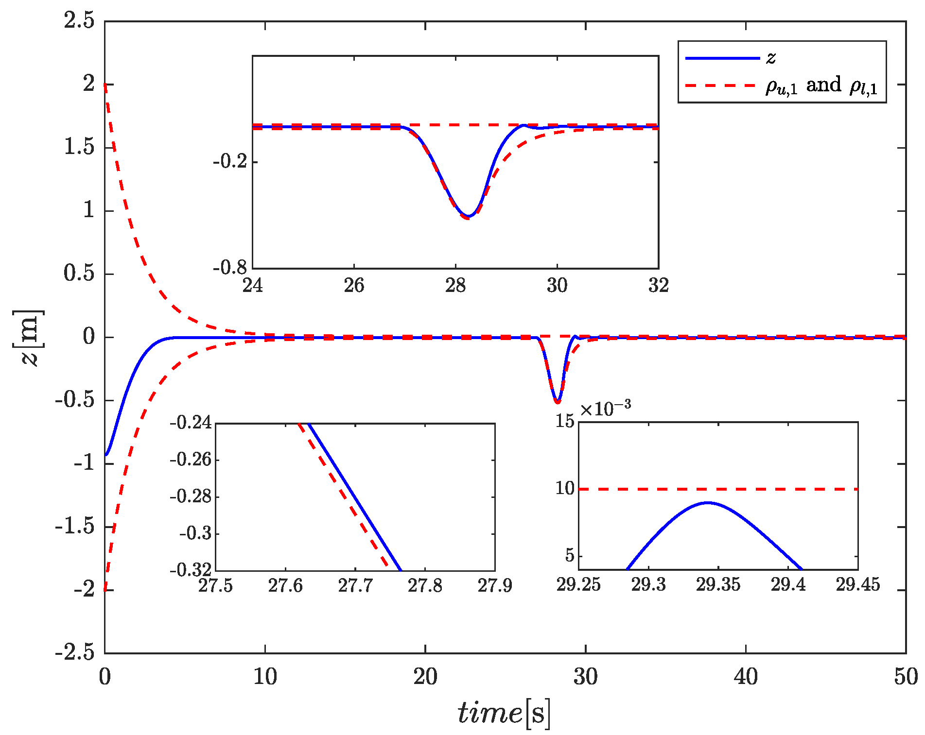
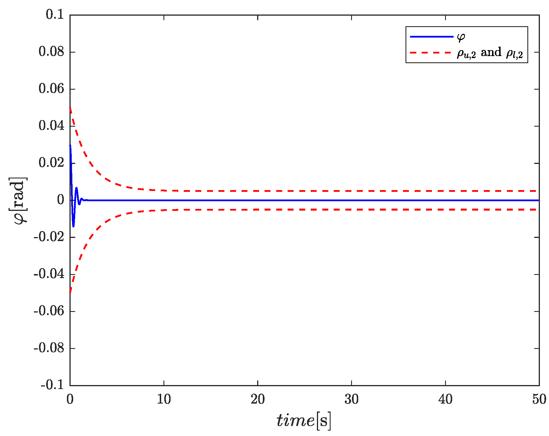
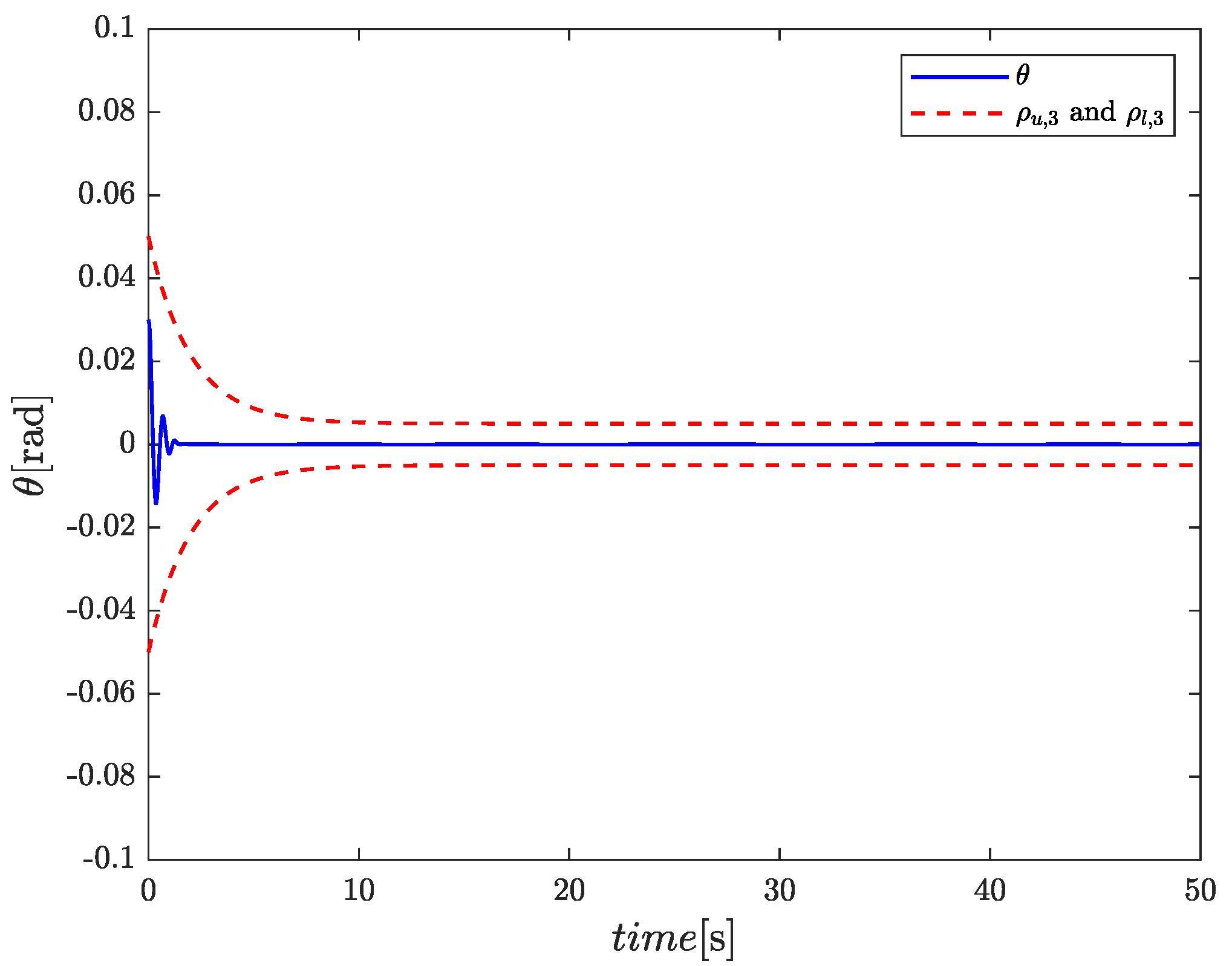
The simulation results in sea state 2 under our proposed adaptive antidisturbance prescribed performance control law are depicted in Figure 2, Figure 3, Figure 4, Figure 5 and Figure 6.
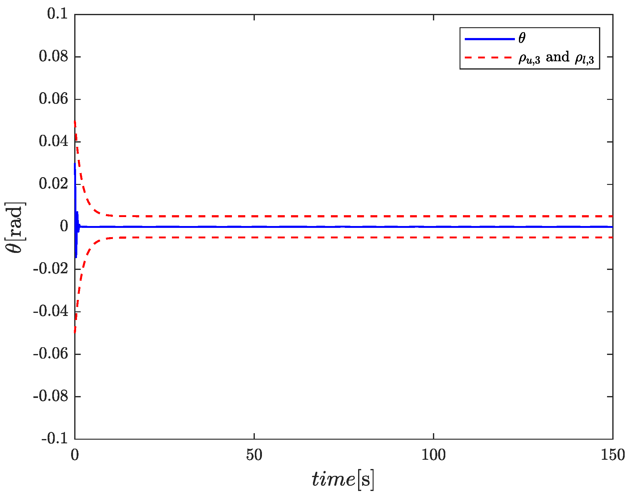
Figure 2, Figure 3 and Figure 4 present the heave displacement, roll angle, and pitch angle of the test platform, respectively. These results demonstrate that the proposed control law effectively maintains the position and orientation of the test platform at the desired constant value q d = [ 0 m , 0 rad , 0 rad ] T , while ensuring that the tracking error e i satisfies the prescribed performance constraints. Notably, around the 6-s mark, the load induced by helicopter landing causes input saturation in the platform. As a result, the stabilization error approaches the performance boundary and the control input is no longer able to bring the error back. At this point, the prescribed performance boundaries are dynamically adjusted upon detection of input saturation, thereby preventing the control error from entering the singular region.
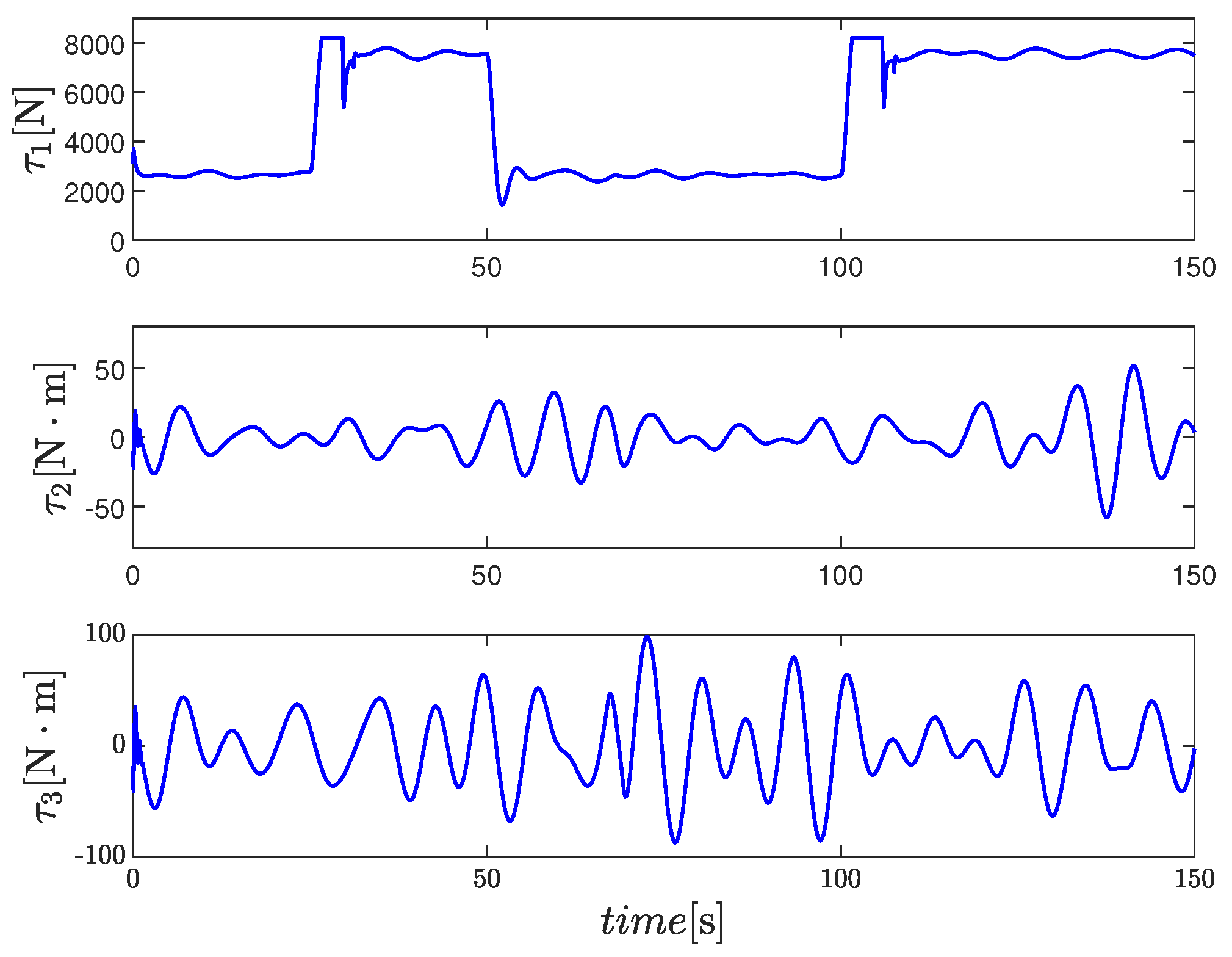
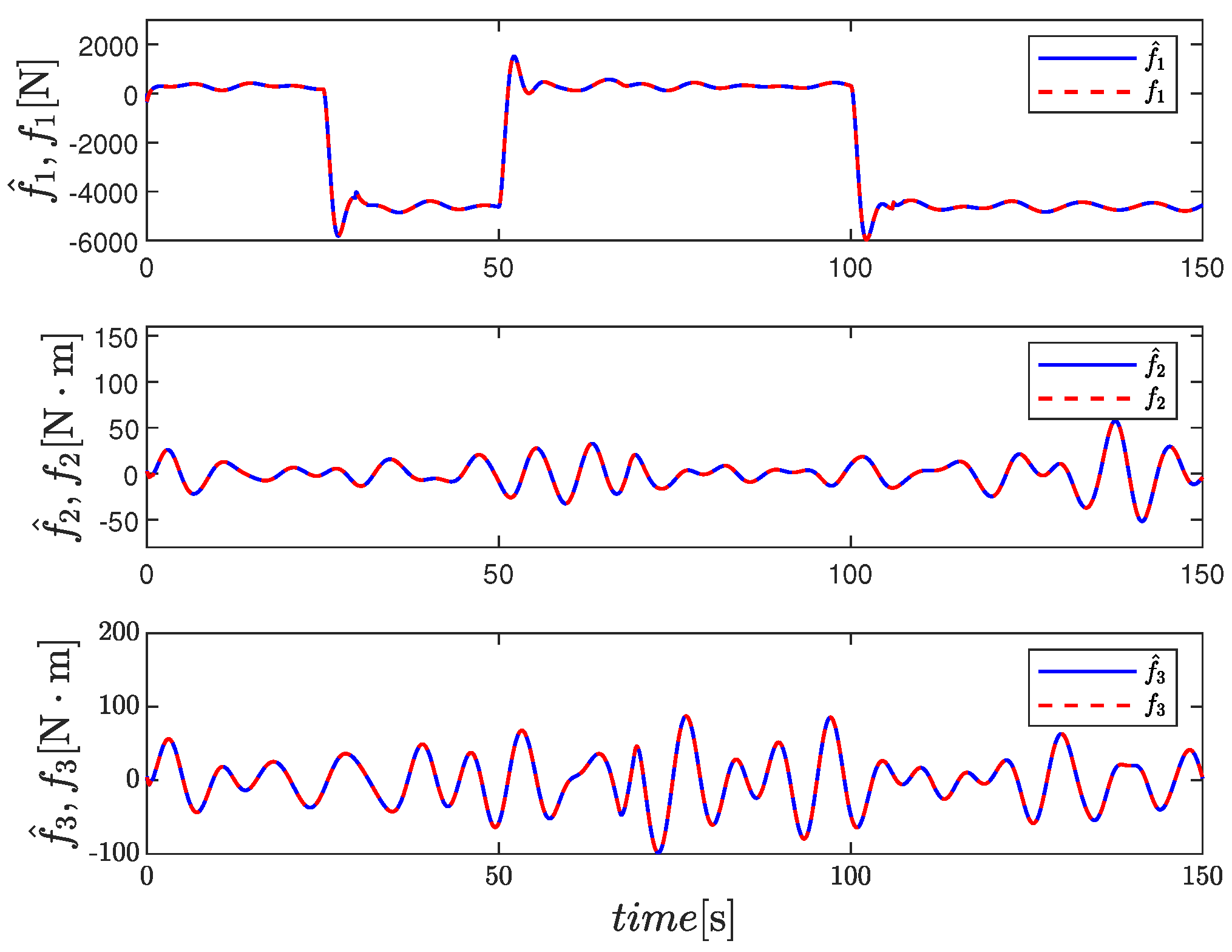
Figure 5 shows that the control inputs of the test platform remain bounded and within reasonable magnitudes. Furthermore, the designed ADS effectively mitigates the adverse effects of input saturation and continues to operate reliably even under repeated saturation conditions. Figure 6 shows the estimate f ^ of the total disturbance vector, consisting of ship-motion-induced disturbances and load force, confirming that the constructed ADE successfully estimates the external disturbances in real time.
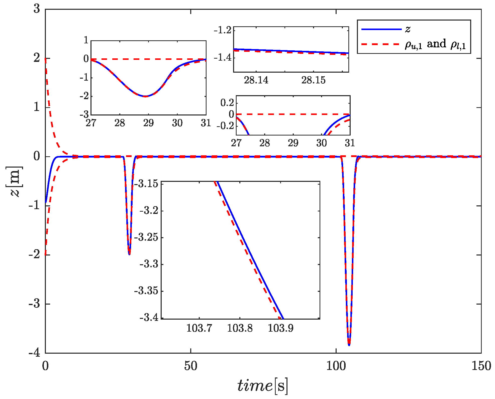
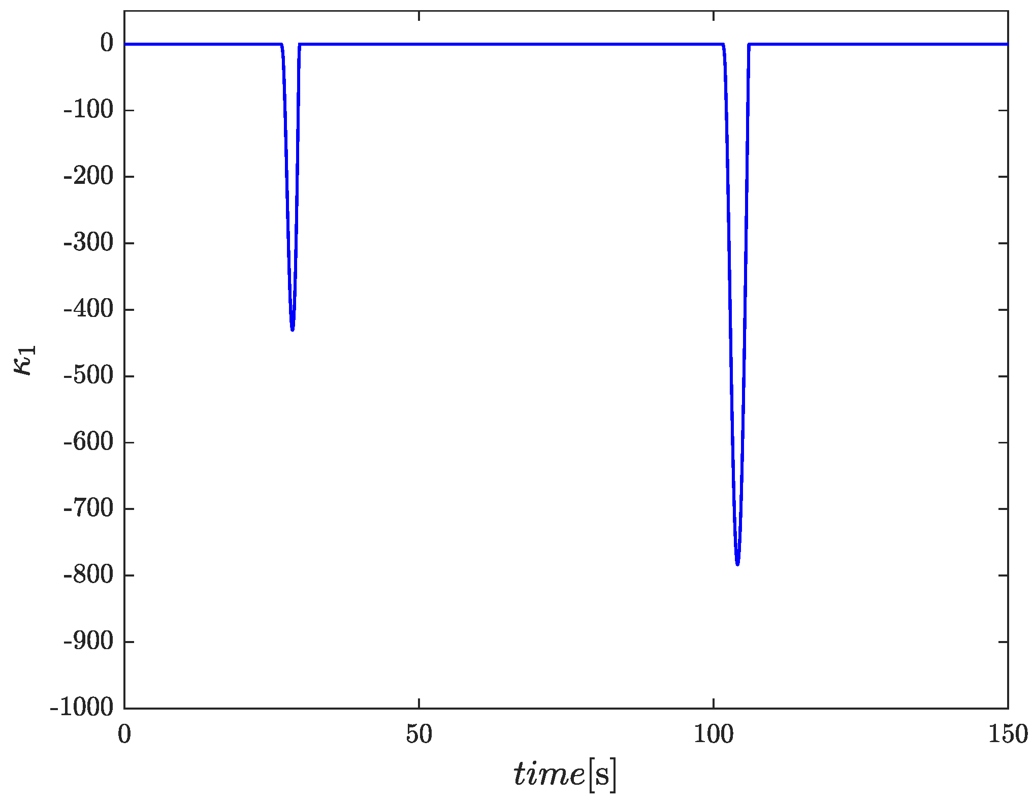
Although the stability analysis is derived under the assumption of a perfectly known model, the proposed controller possesses inherent robustness against model uncertainties. These uncertainties, namely discrepancies in M ( q ) , C ( q , q ˙ ) , and G , are treated as components of a lumped disturbance, which is actively compensated for by the ADE. To experimentally validate this robustness and the controller’s performance under repeated saturation, we conducted additional simulations under Sea State 4. In these tests, the model matrices were perturbed by 10%, (i.e., Δ M ( q ) = 10 % M ( q ) , Δ C ( q ˙ , q ) = 10 % C ( q ˙ , q ) , and Δ G = 10 % G ), and scenarios involving the unmanned helicopter’s take-off at 50 s and subsequent landing at 100 s were introduced. The simulation results in this case under our proposed adaptive antidisturbance prescribed performance control law are depicted in Figure 7, Figure 8, Figure 9, Figure 10 and Figure 11. As shown in Figure 2, Figure 3 and Figure 4 and Figure 7, Figure 8 and Figure 9, the control law maintains satisfactory performance across both sea states, demonstrating strong adaptability to varying sea conditions and robustness to model uncertainties. Specifically, Figure 11 confirms that the designed ADE successfully estimates the total disturbance, which includes the model uncertainties, while Figure 12 verifies its effectiveness in compensating for the input saturation that recurs during the second landing event.

5. Conclusions

This article has proposed a novel adaptive antidisturbance prescribed performance control scheme for AHSs subjected to input saturation and ship-motion-induced disturbances. A saturation-triggered adaptive boundary mechanism was developed to dynamically adjust performance constraints under actuator saturation, thereby effectively resolving the singularity problem inherent in conventional prescribed performance control. Furthermore, a continuous auxiliary dynamic system was designed to mitigate saturation effects, while an ADE based on the internal model principle was constructed to asymptotically estimate and compensate for periodic ship-motion-induced disturbances. By integrating these strategies within the backstepping control framework, the proposed controller ensures that the stabilization error remains within prescribed bounds. Theoretical analysis and simulations demonstrated the effectiveness and robustness of the proposed control law.
Furthermore, the control framework is amenable to practical implementation. Key aspects such as actuator dynamics can be addressed through an inner-loop servo controller, potential time delays may be compensated via ship motion prediction methods, and sensor noise can be accommodated by appropriate selection of the steady-state values of the prescribed performance functions. Future work will focus on the explicit incorporation of actuator dynamics and time delays into the control design, with experimental validation conducted on a laboratory-scale test platform.

Author Contributions

Conceptualization, J.L.; Methodology, J.L.; Validation, J.L.; Investigation, J.L.; Writing—original draft, J.L.; Writing—review & editing, X.H. and J.D.; Funding acquisition, J.L. All authors have read and agreed to the published version of the manuscript.

Funding

This research was funded in part by the National Natural Science Foundation of China [grant numbers 52301413; 52371362; 62273172], in part by the Fundamental Research Funds for the Central Universities [grant number 3132024104], in part by the Taishan Scholars Program of Shandong Province of China [grant number tsqn202507228], in part by Natural Science Foundation of Shandong Province [grant number ZR2024MF055], and in part by Yantai Science and Technology Innovation Development Plan Research Project [grant number 2024JCYJ092].

Data Availability Statement

The original contributions presented in this study are included in the article. Further inquiries can be directed to the corresponding author.

Conflicts of Interest

The authors declare no conflicts of interest.

Appendix A. The Mathematical Model Matrices of the AHS

The inertial matrix is
M ( q ) = m 11 0 0 0 m 22 m 23 0 m 32 m 33
where m 11 = m p , m 22 = I y cos 2 ( φ ) + I z sin 2 ( φ ) , m 23 = m 32 = ( I y I z ) cos ( φ ) cos ( θ ) sin ( φ ) , and m 33 = I z cos 2 ( φ ) cos 2 ( θ ) + I y cos 2 ( θ ) sin 2 ( φ ) + I x sin 2 ( θ ) . Here, m p is the mass of the supporting surface of the AHS, and I x , I y and I z are the moments of inertia of the supporting surface around the O b X b , O b Y b and O b Z b axes, respectively.
The Coriolis-centripetal matrix is
C ( q , q ˙ ) = 0 0 0 0 C 22 C 23 0 C 32 C 33
where C 22 = ( I z I y ) φ ˙ sin ( 2 φ ) , C 23 = C 32 = ( I z I y ) ( θ ˙ cos ( θ ) sin ( 2 φ ) / 2 + φ ˙ cos ( φ ) sin ( φ ) sin ( θ ) ) , C 33 = 2 ( I x I y sin 2 ( φ ) I z cos 2 ( φ ) ) θ ˙ sin ( θ ) cos ( θ ) + 2 ( I y I z ) φ ˙ cos ( φ ) cos ( θ ) sin ( φ ) cos ( θ ) .
The gravity vector is
G = [ m p g 0 0 ] T
where g is the gravity acceleration.

References

  1. Shi, Y.J.; Su, D.C.; Xu, G.H. Numerical investigation of the influence of passive/active flow control on ship/helicopter dynamic interface. Aerosp. Sci. Technol. 2020, 106, 106205. [Google Scholar] [CrossRef]
  2. Su, D.C.; Xu, G.H.; Huang, S.L.; Shi, Y.J. Numerical investigation of rotor loads of a shipborne coaxial-rotor helicopter during a vertical landing based on moving overset mesh method. Eng. Appl. Comput. Fluid Mech. 2019, 13, 309–326. [Google Scholar] [CrossRef]
  3. Newman, S. The safety of shipborne helicopter operation. Aircr. Eng. Aerosp. Technol. 2004, 76, 487–501. [Google Scholar] [CrossRef]
  4. Shukla, S.; Singh, S.N.; Sinha, S.S.; Vijayakumar, R. Comparative assessment of URANS, SAS and DES turbulence modeling in the predictions of massively separated ship airwake characteristics. Ocean Eng. 2021, 229, 108954. [Google Scholar] [CrossRef]
  5. Brewczynski, D.; Tora, G. Dynamic positioning system of helicopter pad on the ship. J. KONES Powertrain Transp. 2014, 21, 21–27. [Google Scholar] [CrossRef]
  6. Brewczynski, D.; Tora, G. Dynamics model of stabilization mechanism for helicopter pad. J. KONES Powertrain Transp. 2016, 23, 61–68. [Google Scholar] [CrossRef]
  7. Campos, A.; Quintero, J.; Saltaren, R.; Ferre, M.; Aracil, R. An active helideck testbed for floating structures based on a stewart-gough platform. In Proceedings of the 2008 IEEE/RSJ International Conference on Intelligent Robots and Systems, Nice, France, 22–26 September 2008. [Google Scholar]
  8. Chen, Y.M.; Ye, J.W.; Zhang, X.L.; Liang, F.L. Experimental study on a stabilized platform system for shipborne helicopter. In Proceedings of the 21st International Offshore and Polar Engineering Conference, Maui, HI, USA, 19–24 June 2011. [Google Scholar]
  9. Erenoglu, L.; Eksin, L.; Yesil, E.; Guzelka, M.J. An intelligent hybrid fuzzy PID controller. In Proceedings of the 20th European Conference on Modelling and Simulation, Bonn, Germany, 28–31 May 2006. [Google Scholar]
  10. Chen, W.; Wang, S.; Li, J.; Lin, C.; Yang, Y.; Ren, A.; Li, W.; Zhao, X.; Zhang, W.; Guo, W.; et al. An ADRC-based triple-loop control strategy of ship-mounted Stewart platform for six-DOF wave compensation. Mech. Mach. Theory 2023, 184, 105289. [Google Scholar] [CrossRef]
  11. Du, Z.; Chen, X.; Zhang, Q.; Yang, Y. An extended state observer-based sliding mode control method for hydraulic servo system of marine stabilized platforms. Ocean Eng. 2023, 279, 114386. [Google Scholar] [CrossRef]
  12. Qiang, H.; Wang, Y.; Wang, R.; Liu, K.; Kang, S.; Yang, J. Model predictive control considering load disturbance of ship-borne hydraulic parallel platform. IEEE Access 2024, 12, 197201–197216. [Google Scholar] [CrossRef]
  13. Tang, G.; Lei, J.; Du, H.; Yao, B.; Zhu, W.; Hu, X. Proportional-integral-derivative controller optimization by particle swarm optimization and back propagation neural network for a parallel stabilized platform in marine operations. J. Ocean Eng. Sci. 2025, 10, 1–10. [Google Scholar] [CrossRef]
  14. Cai, Y.; Zheng, S.; Liu, W.; Qu, Z.; Zhu, J.; Han, J. Adaptive robust dual-loop control scheme of ship-mounted Stewart platforms for wave compensation. Mech. Mach. Theory 2021, 164, 104406. [Google Scholar] [CrossRef]
  15. Wen, Y.; Li, W.; Zhou, S.; Gao, F.; Chen, W. Robust sliding mode control with adaptive gravity estimation of ship-borne Stewart platform for wave compensation. Appl. Ocean Res. 2024, 148, 104004. [Google Scholar] [CrossRef]
  16. Wang, W.; Ning, Y.; Zhang, Y.; Xu, P.; Li, B. Linear active disturbance rejection control with linear quadratic regulator for Stewart platform in active wave compensation system. Appl. Ocean Res. 2025, 156, 104469. [Google Scholar] [CrossRef]
  17. Ahmadi, S.S.; Rahmanii, A. Nonlinear model predictive control of a stewart platform based on improved dynamic model. Int. J. Theor. Appl. Mech. 2020, 18–26. [Google Scholar]
  18. Mochida, R.; Ishimura, K.; Akita, T.; Kon, T. High-precision pointing control using stewart platform with adaptive model predictive control. J. Spacecr. Rockets 2025, 1–18. [Google Scholar] [CrossRef]
  19. Ding, Z.; Zhao, F.; Lang, Y.; Jiang, Z.; Zhu, J. Anti-disturbance neural-sliding mode control for inertially stabilized platform with actuator saturation. IEEE Access 2019, 7, 92220–92231. [Google Scholar] [CrossRef]
  20. Zhang, M.; Guan, Y.; Li, Q.; Sun, Z.; Duan, Z. Adaptive nonlinear control for the stabilized platform with disturbance and input saturation. IEEE Access 2020, 8, 200774–200788. [Google Scholar] [CrossRef]
  21. Hu, A.; Qiao, H.; Yang, W.; Liu, M.; Guo, Y. Stewart platform control input anti-saturation sliding mode controller design. In Proceedings of the 2024 Chinese Intelligent Systems Conference, Guilin, China, 26–27 October 2024; pp. 192–201. [Google Scholar]
  22. Bechlioulis, C.P.; Rovithakis, G.A. Robust adaptive control of feedback linearizable mimo nonlinear systems with prescribed performance. IEEE Trans. Autom. Control 2008, 53, 2090–2099. [Google Scholar] [CrossRef]
  23. Bu, X.; Luo, R. Attitude Control with discrete-time prescribed performance for seeker stabilized platform via event-triggered neural approximation. IEEE Trans. Ind. Inform. 2025, 21, 1853–1861. [Google Scholar] [CrossRef]
  24. Du, J.; Hu, X.; Krstić, M.; Sun, Y. Robust dynamic positioning of ships with disturbances under input saturation. Automatica 2016, 73, 207–214. [Google Scholar] [CrossRef]
  25. Liu, W.; Du, J.; Li, J.; Li, Z. Stabilization control of 3-DOF parallel vessel-borne platform with dynamic uncertainties and unknown disturbances. Appl. Ocean Res. 2022, 126, 103271. [Google Scholar] [CrossRef]
  26. Wang, T.; Yang, H.; Zhang, Q.; Fang, J.; Lai, Z.; Feng, R.; Wei, J.; Wang, Z. Non-inertial dynamic analysis of 3-sps/u parallel platform by screw theory and kane’s method. Actuators 2024, 13, 430. [Google Scholar] [CrossRef]
  27. Yong, K.; Chen, M.; Shi, Y.; Wu, Q. Flexible performance-based robust control for a class of nonlinear systems with input saturation. Automatica 2020, 122, 109268. [Google Scholar] [CrossRef]
  28. Shi, Y.; Xie, W.; Zhang, G.; Dong, H.; Zhang, W. Event-triggered saturation-tolerant control for autonomous underwater vehicles with quantitative transient behaviors. IEEE Trans. Veh. Technol. 2023, 72, 9857–9867. [Google Scholar] [CrossRef]
  29. Wang, Y.; Wang, H.; Zhu, J.; Liu, Y.; Zhang, M.; Su, Z. Flexible prescribed performance-based approaching control for uav aerial recovery under multiwind disturbances. Chin. J. Aeronaut. 2025, 38, 103282. [Google Scholar] [CrossRef]
  30. Krstic, M.; Kanellakopoulos, I.; Kokotovic, P. Nonlinear and Adaptive Control Design; John Wiley & Sons Inc.: New York, NY, USA, 1995. [Google Scholar]
  31. Nikiforov, V. Nonlinear servo compensation of unknown external disturbances. Automatica 2001, 37, 1647–1653. [Google Scholar] [CrossRef]
  32. Levant, A. Higher-Order Sliding Modes, differentiation and output feedback control. Int. J. Control 2003, 76, 924–941. [Google Scholar] [CrossRef]
  33. Ge, S.; Wang, J. Robust adaptive tracking for time varying uncertain nonlinear systems with unknown control coefficients. IEEE Trans. Autom. Control 2003, 48, 1463–1469. [Google Scholar]
  34. Fossen, T.I. Handbook of Marine Craft Hydrodynamics and Motion Control; John Wiley & Sons: Chichester, UK, 2011. [Google Scholar]
  35. China’s New Military Weapons. 2020. Available online: https://www.china-arms.com/2020/12/ar500b-unmanned-helicopter-first-flight/ (accessed on 9 September 2022).
  36. Stanisławski, J. A simulation model for computing the loads generated at landing site during helicopter take-off or landing operation. Trans. Aerosp. Res. 2019, 255, 65–81. [Google Scholar] [CrossRef]
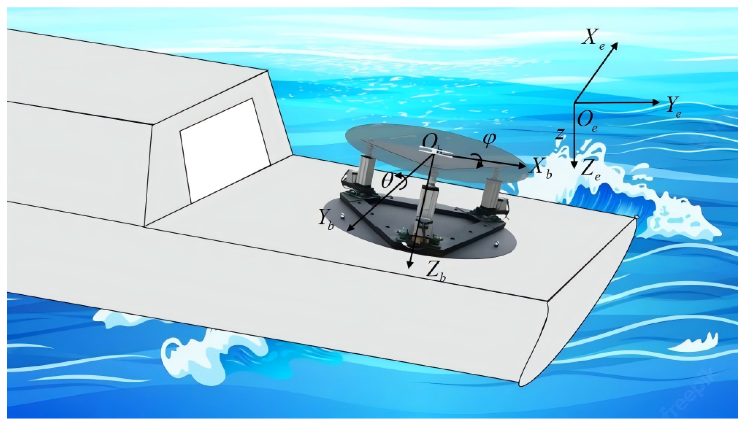
Figure 1. The North-east-down and body-fixed reference frames.
Jmse 13 01949 g001
Figure 2. The heave displacement z in sea state 2.
Jmse 13 01949 g002
Figure 3. The roll angle φ in sea state 2.
Jmse 13 01949 g003
Figure 4. The pitch angle θ in sea state 2.
Jmse 13 01949 g004
Figure 5. The heave force τ 1 , roll moment τ 2 , and pitch moment τ 3 in sea state 2.
Jmse 13 01949 g005
Figure 6. The estimate f ^ s of f in sea state 2.
Jmse 13 01949 g006
Figure 7. The heave displacement z in sea state 4.
Jmse 13 01949 g007
Figure 8. The roll angle φ in sea state 4.
Jmse 13 01949 g008
Figure 9. The pitch angle θ in sea state 4.
Jmse 13 01949 g009
Figure 10. The heave force τ 1 , roll moment τ 2 , and pitch moment τ 3 in sea state 4.
Jmse 13 01949 g010
Figure 11. The estimate f ^ of f in sea state 4.
Jmse 13 01949 g011
Figure 12. The state κ 1 of the ADS in sea state 4.
Jmse 13 01949 g012
Table 1. The parameters the test platform.
ParametersValues
m p 300 kg
I x 10.59 kg· m 2
I y 10.59 kg· m 2
I z 19.85 kg· m 2
g9.8 m/ s 2
Table 2. Main parameters of the supply ship in MSS [34].
ParameterValue
Length between perpendiculars82.8 m
Breadth19.2 m
Draft6 m
Mass 6.3622 × 10 6 kg
Displacement 6.2070 × 10 3 m 3
Table 3. Wave parameter values in different sea conditions [34].
ParameterSea State 2Sea State 4
Spectrum typeITTC
Significant wave height0.5 m2.5 m
Peak frequency0.8 rad/s0.6 rad/s
Mean wave direction 30 120
Wave spreading factor23
Table 4. Main parameters of the unmanned SH AR-500B [35].
ParameterValue
Maximum take-off weight500 kg
Mission load weight70 kg
Maximum endurance time4 h
Operating radius100 km
Maximum endurance speed140 km/h
Cruising speed120 km/h
Table 5. The values of the design parameters.
CategoryParameterValue
Parameters in the
saturation-triggered
boundaries
μ i , j , μ u , j 0.5
ρ 1 , 0 , 1 , ρ u , 0 , 1 2.01
ρ 1 , 0 , 2 , ρ u , 0 , 2 , ρ 1 , 0 , 3 , ρ u , 0 , 3 0.05
ρ 1 , , 1 , ρ u , , 1 0.01
ρ 1 , , 2 , ρ u , , 2 , ρ 1 , , 3 , ρ u , , 3 0.005
ω i 1
ζ i 1.1
Parameters in the
intermediate control vector
K 1 diag ( 2 × 10 4 , 10 4 , 10 4 )
Parameters in the ADS K κ diag ( 7 , 5 , 5 )
λ s , 1 10
λ s , 2 2
κ a 0.01
κ b 0.1
Parameters in the ADE Ω diag ( 1 , 1 , 1 , 1 )
L diag ( 1 , 1 , 1 )
K 0 , i diag ( 30 , 20 , 20 )
Parameters in the control law K 2 diag ( 6 , 5 , 5 )
K 3 diag ( 8 , 5 , 5 )
λ r , 1 10
λ r , 2 2
Disclaimer/Publisher’s Note: The statements, opinions and data contained in all publications are solely those of the individual author(s) and contributor(s) and not of MDPI and/or the editor(s). MDPI and/or the editor(s) disclaim responsibility for any injury to people or property resulting from any ideas, methods, instructions or products referred to in the content.