Article

Optimized Line-of-Sight Active Disturbance Rejection Control for Depth Tracking of Hybrid Underwater Gliders in Disturbed Environments

1
National-Local Joint Engineering Laboratory of Marine Mineral Resources Exploration Equipment and Safety Technology, Hunan University of Science and Technology, Xiangtan 411201, China
2
College of Meteorology and Oceanology, National University of Defense Technology, Changsha 410073, China
*
Author to whom correspondence should be addressed.
These authors contributed equally to this work.
J. Mar. Sci. Eng. 2025, 13(10), 1835; https://doi.org/10.3390/jmse13101835
Submission received: 29 August 2025 / Revised: 18 September 2025 / Accepted: 19 September 2025 / Published: 23 September 2025
(This article belongs to the Section Ocean Engineering)

Abstract

Hybrid underwater gliders (HUGs) combine buoyancy-driven gliding with propeller-assisted propulsion, offering extended endurance and enhanced mobility for complex underwater missions. However, precise depth control remains challenging due to system uncertainties, environmental disturbances, and inadequate adaptability of conventional control methods. This study proposes a novel optimized line-of-sight active disturbance rejection control (OLOS-ADRC) strategy for HUG depth tracking in the vertical plane. First, an Optimized Line-of-Sight (OLOS) guidance dynamically adjusts the look-ahead distance based on real-time cross-track error and velocity, mitigating error accumulation during path following. Second, a Tangent Sigmoid-based Tracking Differentiator (TSTD) enhances the disturbance estimation capability of the Extended State Observer (ESO) within the Active Disturbance Rejection Control (ADRC) framework, improving robustness against unmodeled dynamics and ocean currents. As a critical step before costly sea trials, this study establishes a high-fidelity simulation environment to validate the proposed method. The comparative experiments under gliding and hybrid propulsion modes demonstrated that OLOS-ADRC has significant advantages: the root mean square error (RMSE) for depth tracking was reduced by 83% compared to traditional ADRC, the root mean square error for pitch angle was decreased by 32%, and the stabilization time was shortened by 14%. This method effectively handles ocean current interference through real-time disturbance compensation, providing a reliable solution for high-precision HUG motion control. The simulation results provide a convincing foundation for future field validation in oceanic environments. Despite these improvements, the study is limited to vertical plane control and simulations; future work will involve full ocean trials and 3D path tracking.

1. Introduction

Underwater gliders (UGs) are autonomous underwater vehicles driven by net buoyancy, characterized by low power consumption, long range, and low manufacturing and maintenance costs. They are suitable for large-scale, long-duration, and three-dimensional continuous underwater data collection tasks [1]. In 1989, the American oceanographer Stommel first proposed the concept of UGs. After decades of development, they have become one of the important underwater mobile observation platforms. Currently, commercial UGs such as Slocum [2], Seaglider [3], “Petrel” [4], and “Sea-Wing” [5] are widely used in various marine field surveys.
Due to their low cost and strong endurance, UGs are extensively applied in marine scientific research and observation tasks [6,7]. However, relying solely on buoyancy adjustment devices limits their speed and maneuverability, making it difficult to observe rapidly evolving or transient marine phenomena [8]. HUGs combine buoyancy adjustment devices with thrusters, integrating the advantages of UGs and AUVs. Current HUGs under development include Memorial University’s Slocum AUV [9], the Hybrid Glider designed by Bachmayer et al. [10], the Tehys AUV developed by Monterey Bay Aquarium Research Institute [11], the Petrel-II Hybrid Glider developed by Tianjin University [12], and the ZJU Glider developed by Zhejiang University [13].
Currently, there are few studies on the motion behavior of HUGs, so we can refer to the control methods of UG and AUV. HUGs need to dive or float to the set depth with a certain pitch angle and adjust the pitch angle in time according to different depth deviation values [14]. Therefore, in the process of HUG motion control, the desired pitch angle should be adjusted in real time according to the depth error, and HUGs should be controlled to move at a suitable pitch angle to achieve better dynamic characteristics [15]. Fan et al. [16] designed a proportional integral derivative (PID) controller to correct the heading angle and pitch angle of an underwater glider moving in ocean currents to control the trajectory; however, the error in PID control increases over time, eventually resulting in a significant deviation. Bhatta et al. [17] proposed a nonlinear feedback control strategy for stabilizing the trajectory of an underwater glider, not taking into account the impact of environmental disturbances on navigation. Su et al. [18] proposed a control strategy based on self-imposed disturbance control and reinforcement learning to ensure the attitude angle of an underwater glider is stabilized in the ocean currents—the requirements for the hardware are quite high, and an extremely large platform is needed to accommodate it. Zhou et al. [19] proposed a double closed-loop control structure based on integral sliding mode control and adaptive robust time lag control to track and control the effective depth as well as the attitude of the UG. The effect of ocean currents on the motion of the UG is not considered in the above trajectory control study. While these studies contribute to HUG control, they often neglect real-time ocean current effects or rely on idealized models.
It is difficult to communicate underwater, and the HUG does not receive command signals for real-time maneuvering while in motion, so it needs to have some autonomous guidance capability. LOS guidance is widely used in the military field and is an important guidance method in missile guidance [20,21]. LOS guidance generally includes three points, i.e., the target point, the reference point, and the tracking point, and LOS guidance is a very typical three-point guidance method [22]. According to the basic idea of LOS, the guidance method is applied to the navigation control of UUV to provide a reference value for the pitch angle. Lefeber et al. [23] used the LOS method to obtain the desired heading during the ship’s movement. Based on the values of the desired heading and track deviation as inputs, the method controlled the ship’s heading to ensure convergence to the desired path. Fossen et al. [24], using the LOS guidance as a base, designed and improved a line-of-sight guidance with online estimation of sideslip angle and proposed a trajectory tracking control. The above study assumes constant look-ahead distances, leading to poor adaptability in dynamic environments. These gaps motivate the need for an adaptive guidance law combined with robust disturbance rejection.
This paper proposes a longitudinal plane motion control method for HUGs, incorporating OLOS and ADRC for depth tracking control. The main research is as follows:
  • Addressing the HUG longitudinal plane motion control problem, its kinematics and dynamic models are combined for control. Kinematically, LOS guidance transforms the depth control problem into a line-of-sight distance tracking problem. To address error accumulation issues with the traditional LOS look-ahead distance, an OLOS method is proposed to adaptively adjust the look-ahead distance.
  • Dynamically, active disturbance rejection control (ADRC) is employed. A tracking differentiator optimized with the tangent Sigmoid function (TSTD) enhances the disturbance–observation capability of the extended state observer (ESO) within the ADRC framework for unknown system dynamics and environmental disturbances. Aiming at HUG motion characteristics, control performance during attitude transitions is improved, drift error caused by overshoot is reduced, and adaptability to the marine environment is enhanced.
  • The proposed control method is validated through experiments. Comparative experimental results show the effectiveness of the proposed control method in depth tracking control and disturbance rejection under specified requirements, demonstrating significant performance improvements.
The overall structure of this paper is as follows: Section 2 introduces the kinematics and dynamics models of the HUG in the longitudinal plane; Section 3 details the OLOS-ADRC method; Section 4 presents HUG control experiments; and Section 5 provides the conclusion.

2. Mathematical Model of Hybrid Drive Underwater Glider

2.1. Working Principle of Hybrid Drive Underwater Glider

In addition to the longitudinal “Z” motion, HUG also contains a fixed-depth motion, so it is necessary to model its longitudinal dynamics before parameter identification. The form of underwater motion is shown in Figure 1.
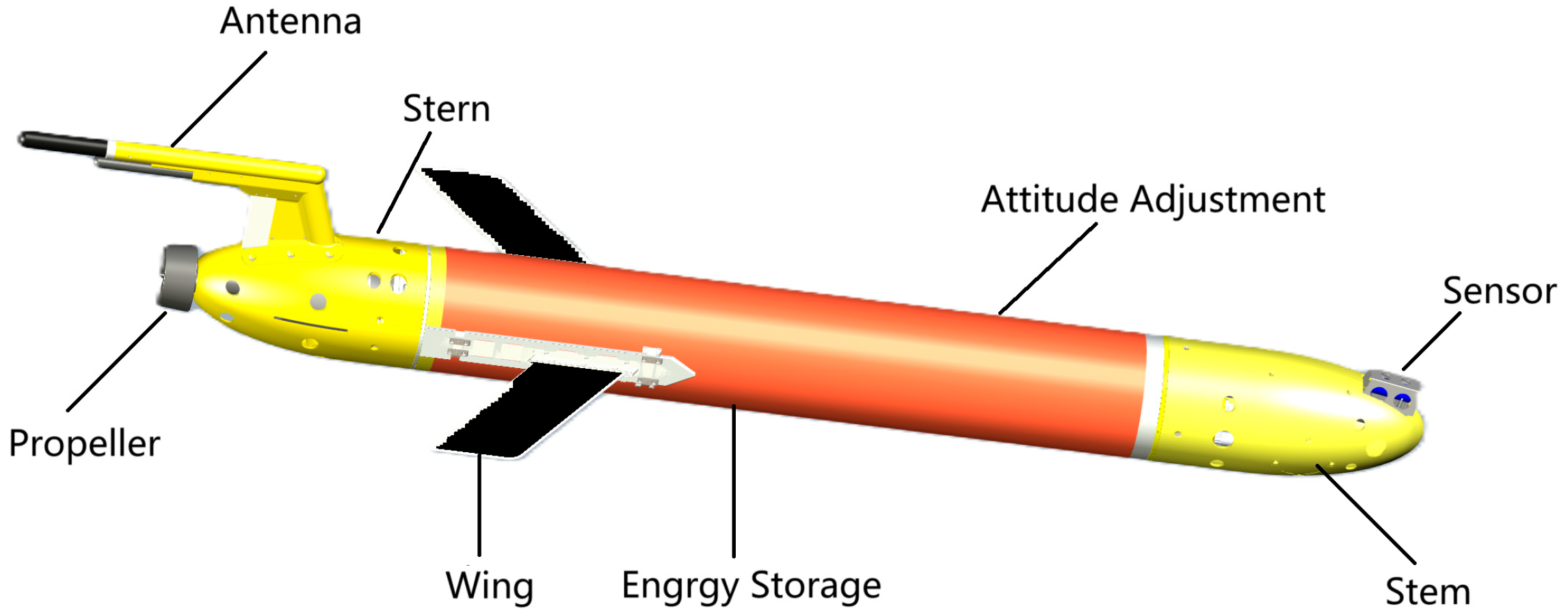
The HUG can be divided into four parts: the shell part, the regulating part, the electrical part, and the propeller part. The structure of the HUG is shown in Figure 2. Specifically, the shell part is in contact with water, and the wing and rudder are connected to the shell mounting. The regulating section includes a sealed structure for the attitude control system and the buoyancy regulation system. The attitude control system regulates the attitude angle of the HUG by moving and rotating the internal mass. The buoyancy adjustment system regulates net buoyancy by changing the volume of the HUG’s oil bladder. The electrical section includes control and signal processing boards, navigation equipment, and energy sources. Thrusters can provide stable propulsive power in resistance to ocean disturbances, when quickly passing through an area, or in fixed-depth navigational movements, and producing less noise and reducing detectability.

2.2. Kinematics and Dynamics Models

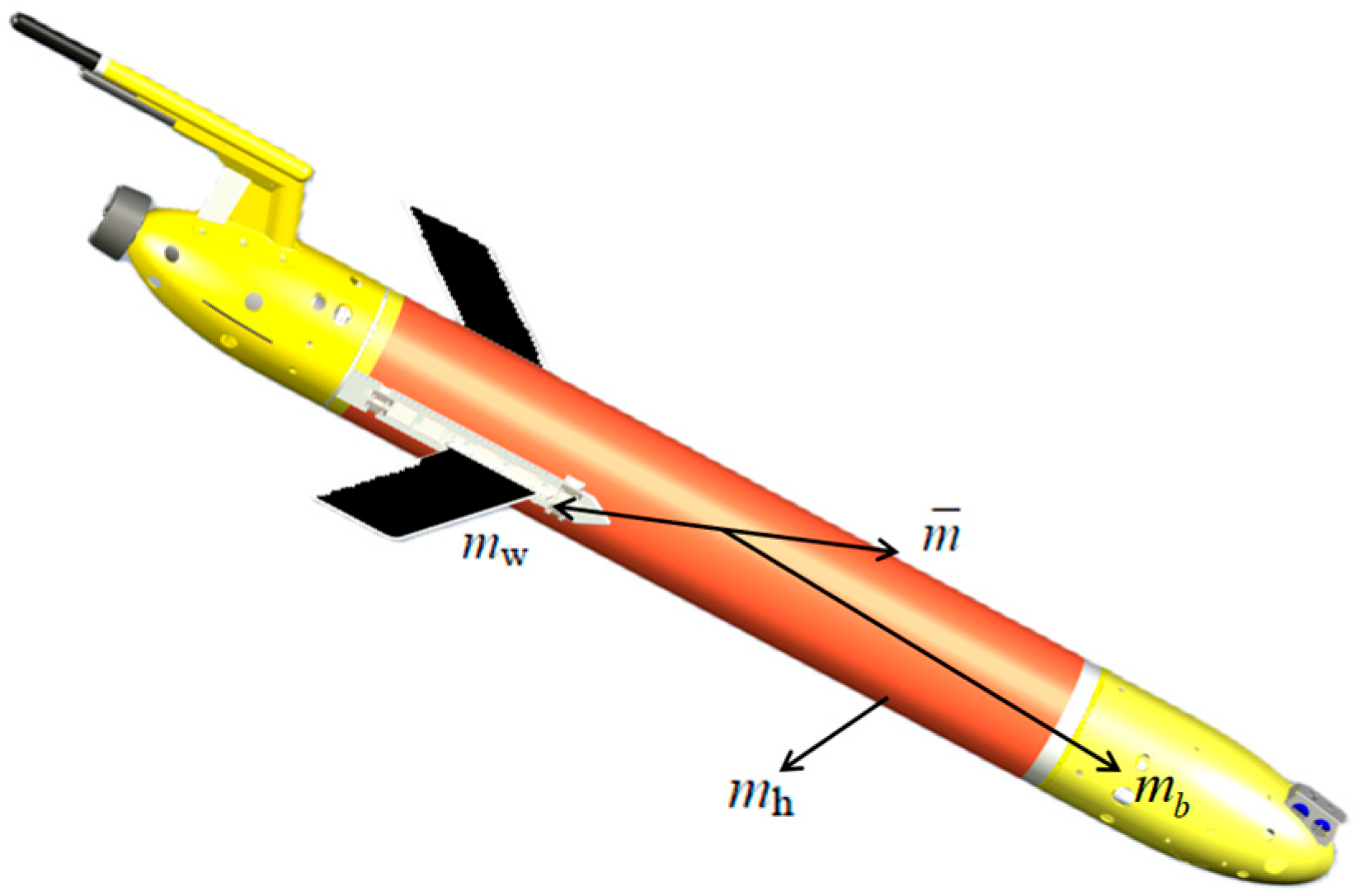
In modeling, the parts of the HUG are abstracted into a series of plasmas, and the whole can be regarded as a system composed of these plasmas, as shown in Figure 3.
The mass of the shell is m h , the mass of the counterweight is m w , and the position of these two masses is fixed. The HUG changes its volume and thus its net buoyancy by means of a buoyancy drive unit mounted on its head. The buoyancy drive unit is abstracted here as a mass with a variable mass of m b , but with a fixed position. The pitch adjustment unit can be regarded as a mass block m ¯ moving in the direction of the main axis of the HUG, which realizes the adjustment of the pitch attitude by generating a pitching moment through its own movement. The roll adjustment unit can be regarded as an eccentric mass block rotating around the main axis, which generates a roll torque on the main axis of the glider through its own rotation to regulate the roll attitude of the HUG. In the actual design, the pitch adjustment unit and the roll adjustment unit of HUG are the same mass block for m ¯ . The propulsion unit is mounted on the tail of the glider, and HUG achieves power compensation by generating thrust through the thrusters.
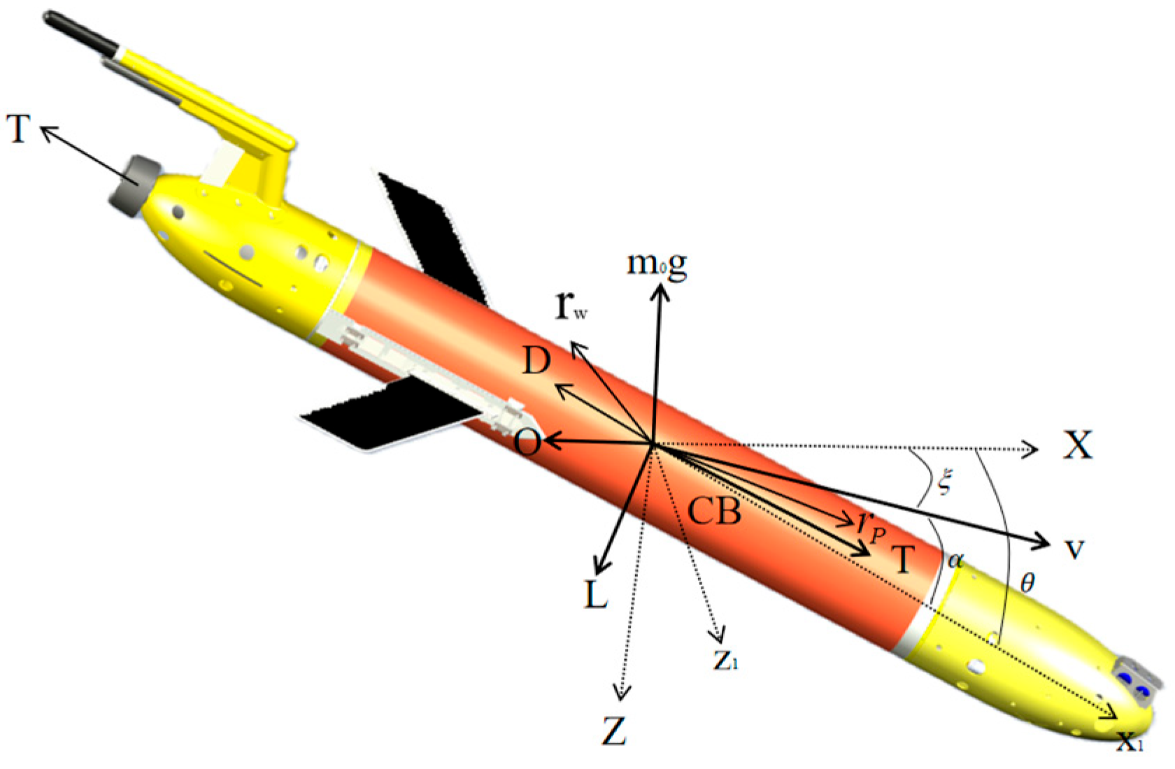
In order to describe the dynamics model of HUG, it is first necessary to define the inertial coordinate system and the body coordinate system. The inertial coordinate system (O-XYZ) selects any point on the horizontal plane as the origin, the OX axis direction is along the main heading direction of the HUG, the OZ axis is vertically downward, and the OY axis direction satisfies the right-hand rule. The origin of the body coordinate system (O-x1y1z1) is located at the floating center CB of the HUG, the Ox1 axis points to the head along the axis of the HUG body, the Oz1 is perpendicular to the Ox1 axis and points to the lower part of the HUG, and the direction of the Oy1 satisfies the right-hand rule. The definition of the specific coordinate system is shown in Figure 4.
The force analysis of the HUG in the vertical plane includes the following: Gravity (W), acting downward at the center of gravity (CG); Buoyancy (B), acting upward at the center of buoyancy (CB); Hydrodynamic forces—lift (L) perpendicular to flow, drag (D) parallel to flow, and pitching moment ( M D L ) at the hydrodynamic center; and Thrust (T), generated by the tail-mounted propeller.
When the HUG moves underwater, it will be subject to hydrodynamic force, and the magnitude of the hydrodynamic force directly determines the result of the glider’s movement. The hydrodynamic forces are mainly lift force L, drag force D, and longitudinal inclination moment M. Research paper [25] indicates that the force and longitudinal inclination moment have an approximately linear relationship with the angle of attack, and the drag force has an approximately quadratic relationship with the angle of attack, expressed as follows:
D = 1 2 ρ C D ( α ) A V 2 K D 0 + K D α 2 v 1 2 + v 3 2
L = 1 2 ρ C L ( α ) A V 2 K L 0 + K L α v 1 2 + v 3 2
M D L = 1 2 ρ C M ( α ) A V 2 K M 0 + K M α v 1 2 + v 3 2
where ρ is the density of seawater, A is the cross-sectional area of the glider, v 1 and v 3 are the horizontal and vertical components of the combined velocity, α is the angle of attack, C D ( α ) , C L ( α ) , and C M ( α ) are the hydrodynamic parameters to be identified, the hydrodynamic parameters K D 0 , K D , K L 0 , K L , K M 0 , and K M can be further derived based on the fact that the three are known, and V 2 = v 1 2 + v 3 2 is the magnitude of the resultant velocity of the glider.
The hydrodynamic coefficients K D 0 , K D , K L 0 , K L , K M 0 , and K M were initially derived from CFD simulations and subsequently refined through system identification using experimental data from the towing tank. Data from sensors were used to fit the model parameters via nonlinear least-squares optimization.
Based on the force analysis, the Lagrangian method is used to establish the dynamic equations of HUG in the longitudinal plane as [25]:
x ˙ = v 1 cos θ + v 3 sin θ
z ˙ = v 1 sin θ + v 3 cos θ
θ ˙ = q
q · = 1 J 2 m 3 m 1 v 1 v 3 r P 1 P P 1 + r P 3 P P 3 q m p g r P 1 cos θ + r P 3 sin θ + M D L r P 3 u 1 + r P 1 u 3
v ˙ 1 = 1 m 1 m 3 v 3 q P P 3 q m 0 g sin θ + L sin α D cos α u 1 + T
v ˙ 3 = 1 m 3 m 1 v 1 q + P P 1 q + m 0 g cos θ L cos α D sin α u 3
r ˙ P 1 = 1 m p P P 1 v 1 r P 3 q
r ˙ P 3 = 1 m p P P 3 v 3 r P 1 q
P ˙ P 1 = u 1 P ˙ P 3 = u 3
m ˙ b = u 4
where P ˙ P 3 is the force acting in the radial (vertical) direction of the slider; m 0 is net buoyancy power for gliders ( m 0 is the difference between the total mass of the glider and the drained mass, positive downwards); m p is the internal slider mass; J 2 is the glider system moment of inertia; g is the standard acceleration of gravity; D is the drag force on the glider; L is the lift applied to the glider; T 2 is the pitching moment applied to the body; v 1 , v 3 is the velocity of the body in the vertical and horizontal directions; θ is the pitch angle, θ [ 30 , 30 ] ; q is the angular velocity of the pitch angle change; α for the angle of attack; r p 1 , r p 3 is the position of the slider in the body coordinate system; P p 1 , P p 3 is the momentum of the system acting on the slider; u 1 , u 3 is the control input for the sliding mass and represents the force acting in the axial and vertical direction of the slider mass; u 4 is the buoyancy system mass control input, which represents the rate of change in the buoyancy system mass. m 1 = m b + m h + m f 1 , m 3 = m b + m h + m f 3 , m b is variable ballast mass located at CB, m h is uniformly distributed hull mass, m f 1 , m f 3 is the hydrodynamic additional mass of the glider in the axial and vertical directions; and T is for the thrusters.

3. Optimization of LOS Guidance

3.1. LOS Guidance

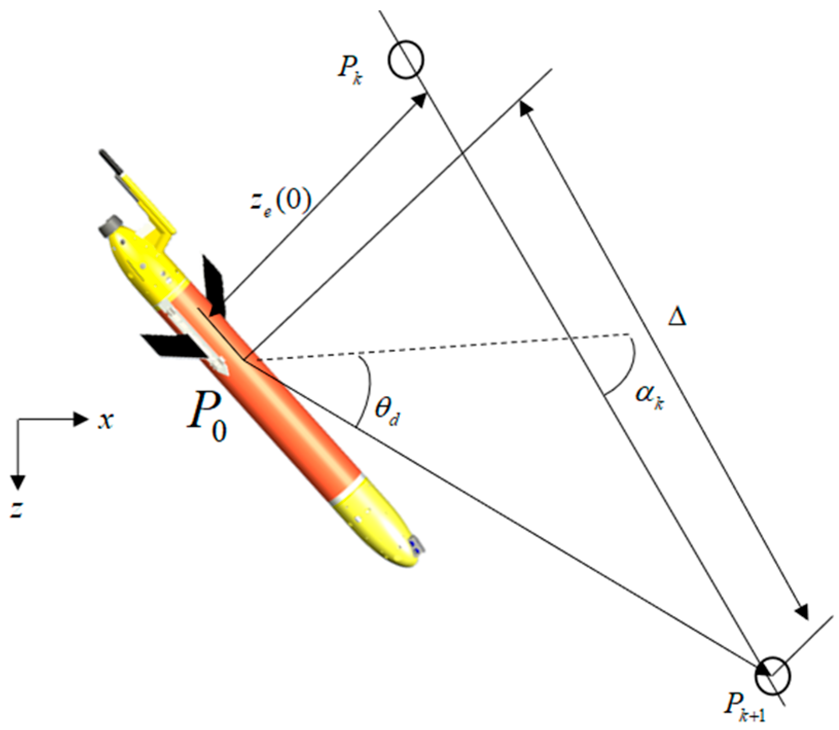
LOS guidance is a classical and effective guidance tracking strategy. In this study, we optimize the traditional LOS guidance and design an adaptive adjustment of a forward-looking distance method. The schematic diagram of LOS guidance is shown in Figure 5. The position deviation is converted into heading deviation, and the combined velocity direction of the HUG is controlled to always be aligned with the LOS vector point Pk+1 on the desired heading, which guides the HUG to approximate the desired trajectory.

3.2. Optimize LOS Guidance

In the geodetic coordinate system, the azimuth angle α k of the desired trajectory is the angle between the desired trajectory and the longitudinal axis of the geodetic coordinate system:
α k = atan 2 ( y k + 1 y k , x k + 1 x k )
The atan 2 ( y , x ) function computes the four-quadrant inverse tangent, returning the angle between the positive x-axis and the point (x, y), resolving ambiguities in quadrant identification.
The vertical deviation of the HUG real-time position P0 (x0,y0) to the desired trajectory PkPk+1 is as follows:
y e ( 0 ) = ( y 0 y k ) cos α k ( x 0 x k ) sin α k
Define the distance from the plumb point of the HUG real-time position on the desired trajectory to the line-of-sight point Pk+1 as the forward-looking distance Δ, which is generally chosen to be an integer multiple of the length of the HUG, Δ = n*L, where n is generally taken as 2~6 and L is the length of the HUG.
θ is the actual heading angle of the HUG:
θ = α k atan 2 ( y e ( 0 ) , Δ )
The selection of the forward-looking distance Δ affects the magnitude of the desired heading angle. When Δ is larger, the vector point is selected farther away and the HUG will approach the desired course slowly, and as Δ decreases, the HUG approaches to the desired course faster, but it is prone to oscillations, overshooting, and instability.
Considering that when the HUG is far from the desired trajectory, the primary goal is to quickly approach it and reduce lateral error. At this point, a smaller look-ahead distance should be selected. When the HUG is near the desired trajectory, a larger look-ahead distance should be selected to allow the HUG to approach slowly, minimizing overshoot. Therefore, vertical distance ze(0) and exponential function parameter λ are introduced for dynamic adjustment. The parameter λ is designed considering low-speed motion characteristics, using the OLOS (Optimized Line-of-Sight) method for adaptive look-ahead distance adjustment:
Δ = ( Δ max Δ min ) exp λ z e 2 ( 0 ) W + Δ min
where Δ max and Δ min are the designed maximum and minimum look-ahead distances, generally selected as integer multiples of L; λ is a design coefficient, λ > 0 . W is the magnitude of the glider’s resultant velocity. When the HUG moves at low speed ( W ≤ 0.5 m/s), increasing λ can enhance the sensitivity of look-ahead distance adjustment.
When the HUG is farther from the desired route, y e ( t ) is larger, and Δ = Δ min , drives the HUG to rapidly approach the desired course. As the HUG approaches the desired trajectory, y e ( 0 ) decreases and Δ becomes larger and closer to Δ max , which allows the HUG to approach the desired course more smoothly, effectively reducing the overshooting of the position error.
The dynamic adjustment strategy of the parameter Δ is theoretically grounded in the Lyapunov-based control framework and the concept of exponential convergence. When y e ( t ) is large (indicating significant path deviation), Δ is set to Δ min to enforce rapid convergence. As y e ( t ) decreases, Δ smoothly increases toward Δ max , promoting gradual stabilization near the desired trajectory. This dual-phase mechanism achieves two critical objectives:
(1)
Fast Transient Response: With Δ = Δ min , the system exhibits high-gain behavior, driving y e ( t ) toward zero exponentially. This phase minimizes the settling time during large initial errors.
(2)
Overshoot Suppression: As y e ( t ) 0 , increasing Δ reduces the control aggressiveness. The smooth transition to Δ max ensures bounded control inputs, thereby attenuating oscillations and suppressing overshoot.
In Formula (17), the look-ahead distance parameters are empirically set as Δ min = 2   L (to ensure rapid convergence at large cross-track errors), Δ max = 6   L (to minimize overshoot near the desired path), and λ = 0.5 · W 1 (where W is the resultant velocity). This functional form for λ enhances sensitivity at low speeds ( W 0.5   m / s ).
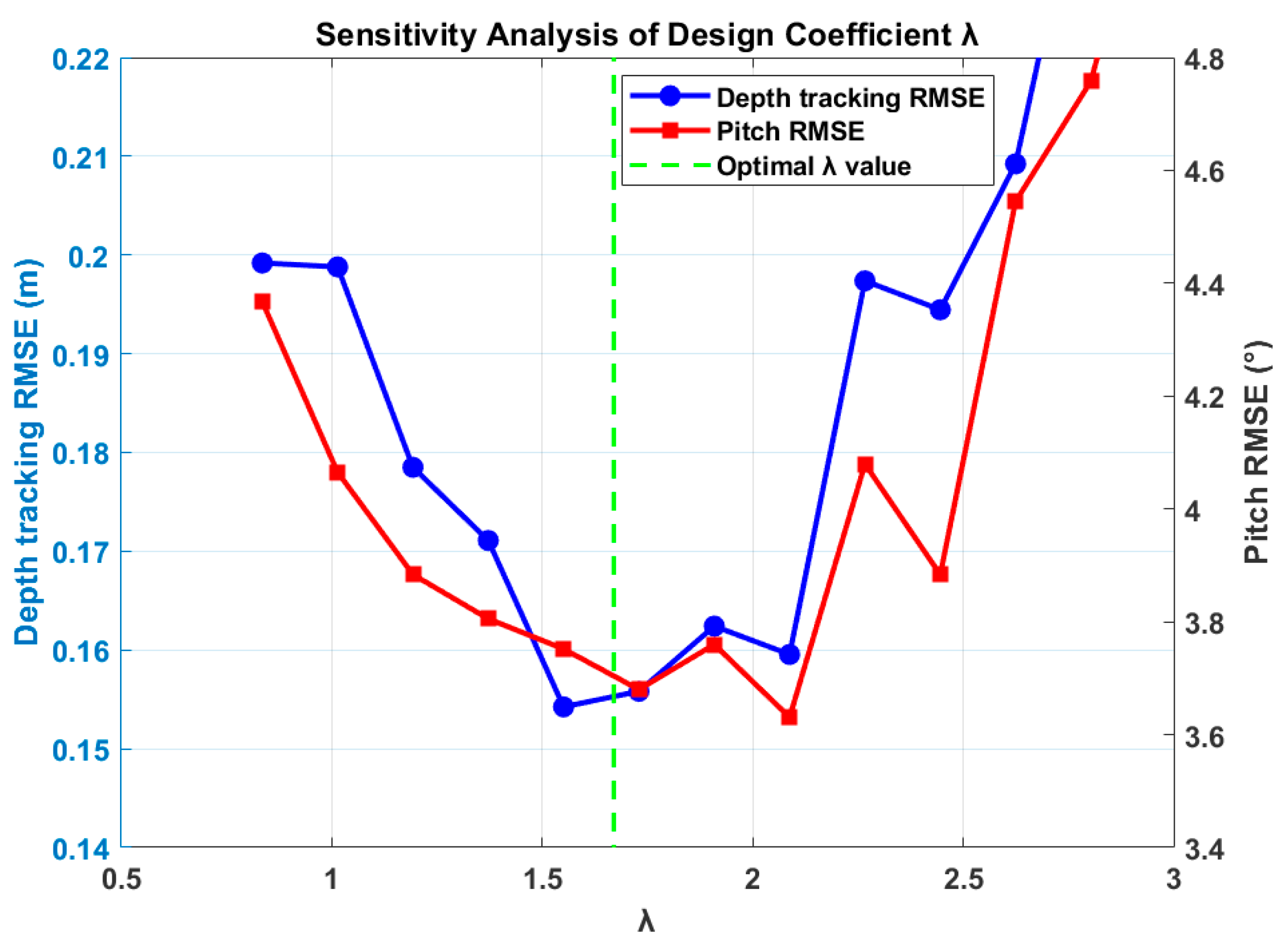
λ is critical as it governs the sensitivity of the look-ahead distance Δ to the cross-track error. A sensitivity analysis was conducted to evaluate the robustness of the controller’s performance to variations in λ . The analysis was performed under the gliding mode at a resultant velocity of W = 0.3 m/s. We defined the baseline value as λ = 0.5 · W 1 ≈ 1.67 and then varied λ over a range from 0.5   λ to 2   λ . The primary performance metric was the Root Mean Square Error (RMSE) of depth tracking.
The results, illustrated in Figure 6, demonstrate that the system performance is robust to a broad range of λ values. The RMSE remained within a low and acceptable bound across the tested range. Specifically, when λ was below optimal λ value, the convergence speed improved slightly at the cost of a minimal increase in overshoot. Conversely, values of λ greater than it resulted in smoother but slightly slower convergence. The baseline value was selected as it provides an optimal trade-off between rapid response and stability, minimizing the overall tracking error. This analysis confirms that the controller does not require extremely precise tuning of λ , enhancing its practicality for real-world applications.

4. ADRC System

HUG always has internal uncertainty (unmodeled dynamics and parameter uncertainty) as well as external uncertainty (unknown perturbations in the external environment) which will lead to a large error between the mathematical model and the actual voyage, which cannot be effectively controlled by traditional control methods. ADRC does not rely on an exact mathematical model of the controlled object, only a relatively simple linearized model is required for design. This makes ADRC more adaptable and flexible in dealing with nonlinear, time-varying, and uncertain systems. It is also capable of estimating and compensating for the total system perturbations (both internal uncertainties and external perturbations) in real time through its built-in ESO, which significantly enhances the system’s immunity to disturbances.

4.1. TSTD

The purpose of the tracking differentiator (TD) is to arrange the transition process v 1 and extract the differential signal v 2 according to the setpoint v , and arranging the transition process is an effective way to achieve fast tracking without overshoot.
The tracking differentiator (TSTD) based on the optimization of tangent sigmoid function has a fast response, high accuracy, and strong noise rejection; therefore, the TSTD is used to optimize the ADRC. Assuming that the input signal is v ( t ) , it can be expressed by the tracking differentiator as follows:
v 1 ( t + 1 ) = v 1 ( t ) + h v 2 ( t )
ν 2 ( t + 1 ) = ν 2 ( t ) + h k 0 2 ( a 1 + a 2 )
a 1 = l 1   |   ν 1 ( t ) ν ( t ) | p tansig [ β 0 ( ν 1 ( t ) ν ( t ) ) ]
a 2 = l 2 tansig [ ν 2 ( k ) k 0 ]
where h is the sampling period, k , l 1 , l 2 , p , and β are the parameters to be adjusted by TSTD, tansig ( x ) is the tangent Sigmoid function.
tansig ( x ) = 2 1 + e ( 2 x ) 1
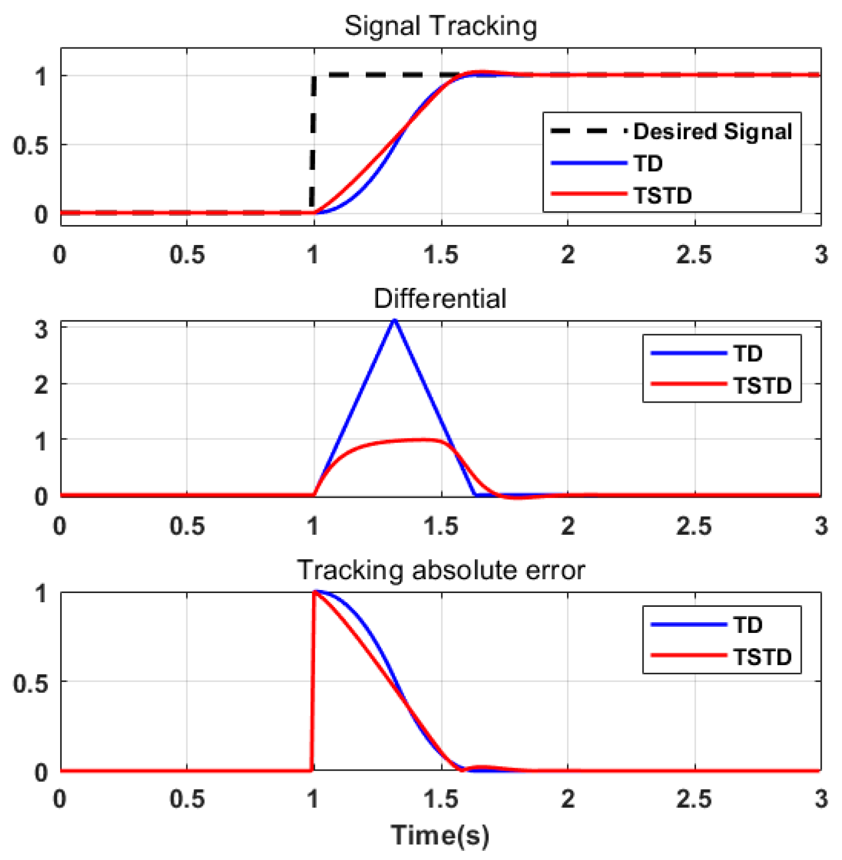
As illustrated in Figure 7, the tracking differentiator (TD) exhibits characteristic rapid response dynamics but incurs significant overshoot (>20%), resulting in pronounced oscillatory attenuation during transient processes. Its differential output generates high-frequency pulses that readily amplify system noise. In contrast, the tangent sigmoid-based tracking differentiator (TSTD) employs a smooth transition strategy to mitigate overshoot. The differential signal of TSTD manifests as a smooth unimodal curve, demonstrating inherent low-pass filtering characteristics that enhance noise suppression capability by over 70%. Given the requirement for smooth transition process control in HUG’s mechanical actuation systems, TSTD represents a more suitable approach for orchestrating depth-tracking transition processes in HUG applications.

4.2. ESO

For the HUG longitudinal plane dynamics model as Formula (7), taking pitch angle control as the controlled object, define the total disturbance term f ( · ) containing all unknown dynamics and external disturbances:
f ( · ) = ( m 3 m 1 ) v 1 v 3 ( r P 1 P P 1 + r P 3 P P 3 ) q m ¯ g ( r P 1 cos θ + r P 3 sin θ ) + M D L r P 3 u 1 + r P 1 u 3
where M D L is the hydrodynamic moment, u 1 , u 3 are control inputs.
Simplify the dynamics model to:
q ˙ = f ( · ) + b 0 u
where b 0 = 1 J 2 is the known partial control gain, u is the equivalent attitude angle input.
Expand the total disturbance f ( · ) into the system’s third state x 3 , obtaining the augmented system:
θ ˙ = q q ˙ = x 3 + b 0 u x ˙ 3 = f ˙ ( · )
Design a third-order extended state observer (ESO):
e = z 1 θ
z ˙ 1 = z 2 β 01 e
z ˙ 2 = z 3 β 02 f 1 + b 0 u
z 3 = β 03 f 2
where z 1 is pitch angle observation value θ , z 2 is pitch angle velocity observation value q , z 3 is total disturbance observation value (including unmodeled dynamics and ocean current interference), f 1 and f 2 are selected as fal ( · ) functions:
f a l ( e , α , δ ) = | e | α sign ( e ) , | e | > δ e δ 1 α , | e | δ
where δ > 0 is the linear interval threshold, used to suppress chattering caused by high-frequency noise.
In ESO, z 3 ( t ) can track the real-time action variable of acceleration in an open-loop system. If the system is observable and acceleration plays a role in it, the effects will be reflected in the output of the system, so that action variables can be extracted from the output information. When parameter b 0 is known, the control variable can be considered as follows:
u = u 0 z 3 ( t ) b 0
where u 0 is the initial variable.
To verify the convergence of ESO, it is necessary to prove that the estimation error e = [ e 1 , e 2 , e 3 ] T is uniformly ultimately bounded (UUB). Define the estimation error as follows:
e 1 = θ z 1 e 2 = q z 2 e 3 = f ( ) z 3
Assumption 1 (Boundedness of Disturbance).
The rate of change in the total disturbance satisfies  | g ( t ) | = | f ˙ ( · ) | G , where  G > 0  is a known constant.
Rationale.
In actual HUG operation, hydrodynamic terms MDL and environmental disturbances (e.g., currents) have physical bounds; internal unmodeled dynamics (e.g., mass block displacement coupling effect) are also limited under mechanical constraints. Hence, the assumption holds.
Theorem 1 (ESO Stability).
Under Assumption 1, if the observer gains  β 01 , β 02 , β 03 , satisfying the Hurwitz condition for the matrix  A e L C , and all eigenvalues of  A e L C  have negative real parts, then the estimation error e is uniformly ultimately bounded (UUB):
A e = β 01 1 0 β 02 0 1 β 03 0 0
Proof.
Define the Lyapunov function candidate. □
V = 1 2 e T e ,   e 0
the error dynamics are derived from Formulas (25)–(29):
e ˙ = ( A e L C ) e + E g ( t )
where L = [ β 01 , β 02 , β 03 ] T , C = [ 1 , 0 , 0 ] , E = [ 0 , 0 , 1 ] T .
Substituting it into Formula (35) gives the following:
V ˙ = e T ( A e L C ) e + e T E g ( t )
Applying the Cauchy–Schwarz inequality and bounded disturbance assumption:
e T E g ( t ) e E g ( t ) e G
Further, by Young’s inequality:
  e G ϵ 2 e 2 + G 2 2 ϵ , ϵ > 0
where ϵ is a small positive constant introduced by Young’s inequality. The bound holds for any ϵ > 0 , and its value can be chosen to minimize the ultimate bound on the estimation error.
Thus,
V ˙ e T A e L C + ϵ 2 I e + G 2 2 ϵ
Since A e L C is Hurwitz, there exists a symmetric positive-definite matrix P such that
( A e L C ) T P + P ( A e L C ) = Q , Q 0
Select ϵ sufficiently small such that A e L C + ϵ 2 I remains Hurwitz. Then,
V ˙ λ min ( Q ) e 2 + G 2 2 ϵ
where λ min ( Q ) > 0 . This implies V ˙ < 0 when e > G 2 ϵ λ min ( Q ) , proving UUB with bound e G ϵ λ min ( Q ) .
Conclusion.
The estimation error   e   is uniformly ultimately bounded.
Theorem 1 establishes UUB stability for longitudinal states under bounded disturbances. Full 3-DOF stability requires further study.

4.3. NLSEF

Nonlinear State Error Feedback (NLSEF) uses the state estimation output z i of the ESO as the state feedback variable of the self-resilient controller, comparing it to the output of the TD. The nonlinear state error feedback law is as follows:
u 0 = β 1 fal ( e 1 , α , δ ) + β 2 fal ( e 2 , α , δ )
where β 1 and β 2 are the control gain.
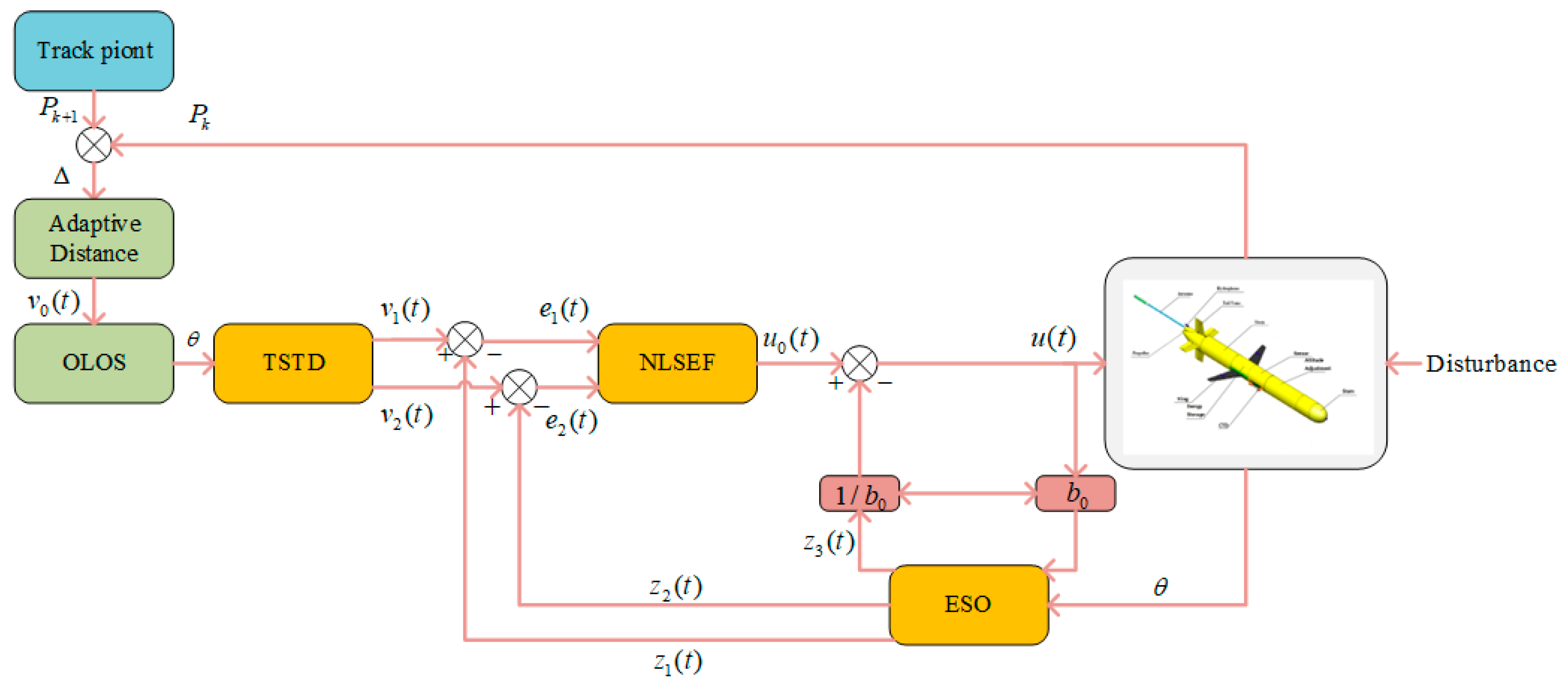
The OLOS-ADRC principle is shown in Figure 8. Where w ( t ) is the disturbance set, z 1 ( t ) and z 2 ( t ) are the state variables of the glider, z 3 ( t ) are the unknown disturbance w ( t ) and the real-time action variables of the uncertain model, b 0 are the compensation coefficients.
Both ADRC and OLOS-ADRC controllers underwent the following identical tuning procedures:
  • Baseline tuning: PID gains ( β 1 , β 2 in Formula (45)) initialized via the Ziegler–Nichols method.
  • ESO optimization: Observer gains ( β 01 , β 02 , β 03 ) adjusted using the Lyapunov stability criterion (Theorem 1), with β 01 = 100 , β 02 = 300 , β 03 = 1000 ensuring λ min ( A e ) > 1 2 .
  • f a l ( · ) calibration: α = 0.5 , δ = 0.05 selected to balance chattering suppression and disturbance sensitivity.
All parameters were fine-tuned via Monte Carlo simulations over 200 trials to guarantee fairness in comparative tests.

5. Comparative Experiment Results

In order to test the control effect of OLOS-ADRC, four sets of comparison tests were conducted on the HUG platform. Two of the groups are control tests for conventional gliding motions, and the remaining two groups are control tests for hybrid-drive motions.
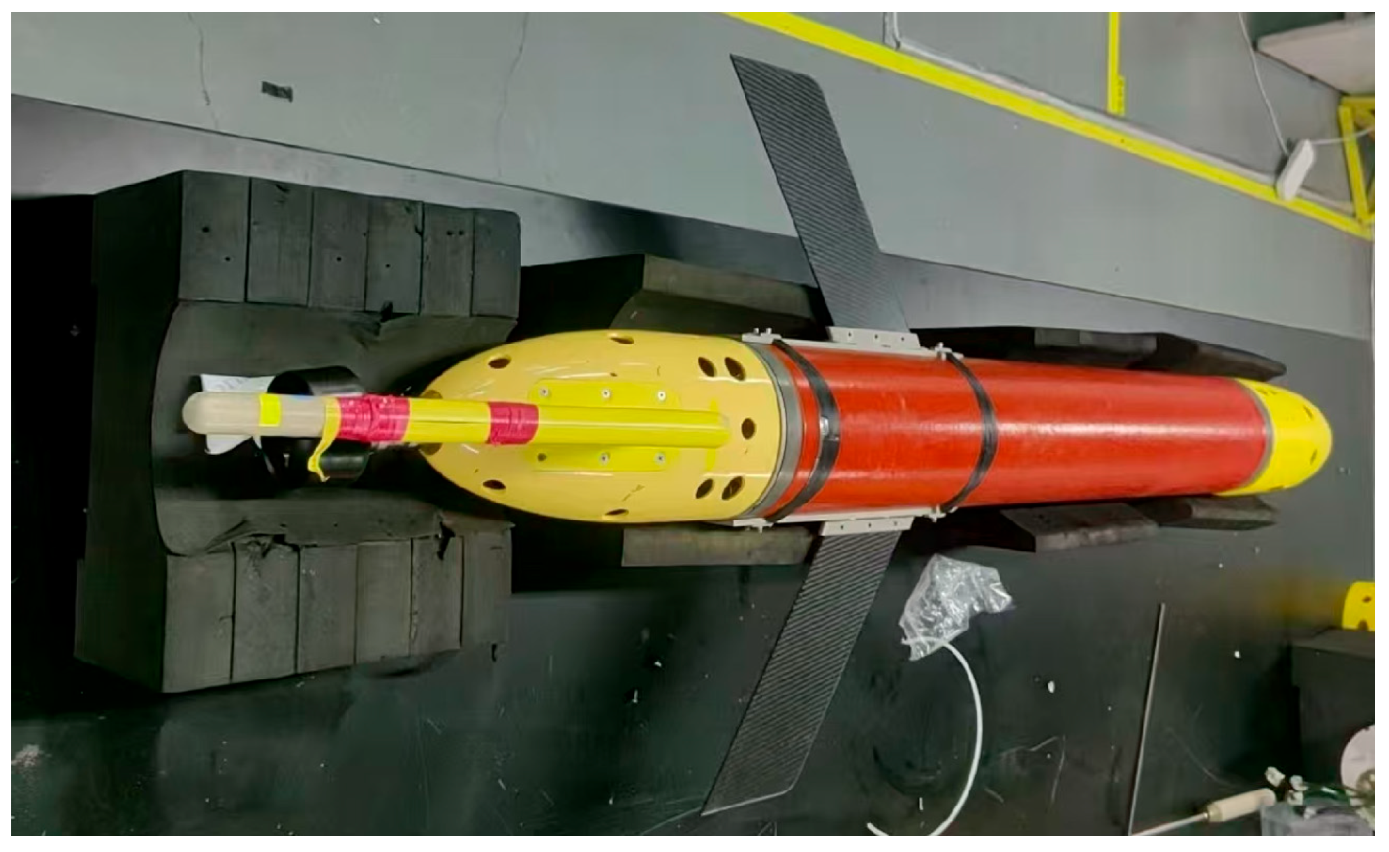
The HUG physical vehicle is shown in Figure 9. The overall structure consists of a watertight compartment, an alloy cabin, and a 3D-printed cabin. The longitudinal plane’s control force is provided by the pitch control system, while the propeller provides the power for maintaining a constant depth during navigation. Most of the electronic components are installed in watertight compartments, such as the depth meter (DMD-210S), global navigation satellite system (GNSS) receiver, portable battery pack, microcomputer, etc. The main technical parameters of HUG are shown in Table 1 below.
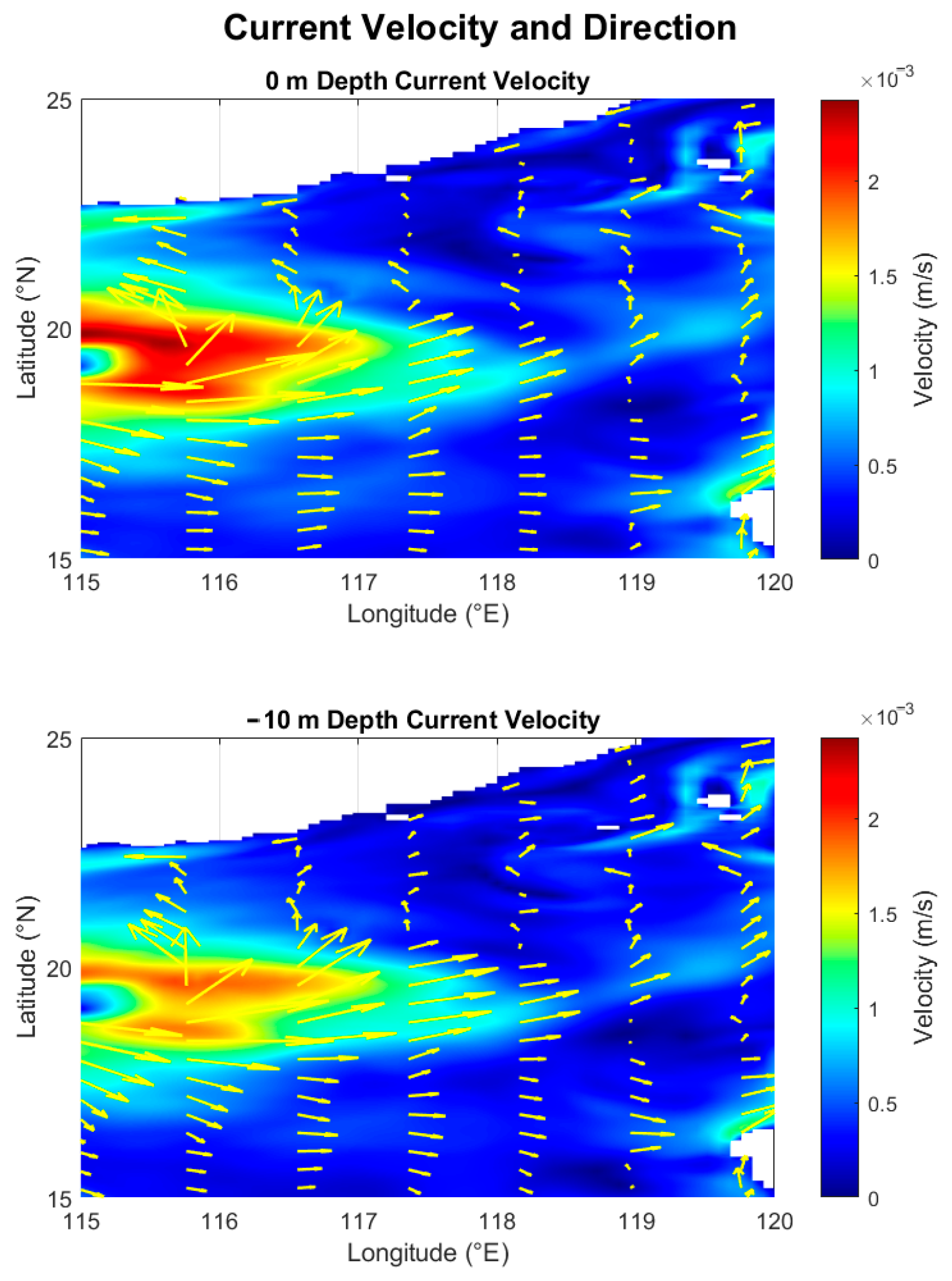
Ocean currents are the main form of water movement in the sea, widely existing in the ocean. The speed and direction of their flow vary with location, and their influence on the movement of underwater gliders cannot be ignored. The real ocean current data used in this article is sourced from HYCOM, specifically the data within the range of 15° N to 25° N and 115° E to 120° E on 1 January 2024. Figure 10 shows the velocity profiles of the ocean currents at different depths at zero moment.
All experiments were conducted in a high-fidelity collaborative simulation environment, built based on MATLAB/Simulink. This platform simulates the complex marine environmental conditions of the South China Sea by integrating realistic time-varying ocean current data from the HYCOM model and the parameters measured by our HUG prototype. The dynamics of the thruster and the response delay of the actuators were also modeled based on bench tests. This simulation framework has been calibrated based on the initial pool tests of our prototype to ensure its credibility in predicting the behavior of the vehicle in disturbed environments.
To verify the performance of the HUG control strategy designed above, the self-developed HUG was subjected to simulation of gliding mode and hybrid drive mode movements. The gliding mode includes descent and ascent, while the hybrid drive mode includes descent, constant-depth navigation, and ascent. The HUG was set to start moving in a periodic manner from approximately 116.9178° east longitude and 20.7141° north latitude, in a direction directly eastward, with a diving depth of 10 m.

5.1. Routine Gliding Exercise Test

The control performance of adaptive dynamic reference control (ADRC) and optimized online dynamic reference control (OLOS-ADRC) was compared through conventional gliding motion tests. Firstly, motion control was carried out under interference-free conditions to observe the depth control during the gliding process and the depth control effect of ESO based on online estimation. Then, real ocean currents were introduced as interference, and the adjustment ability of HUG to the interference was observed.
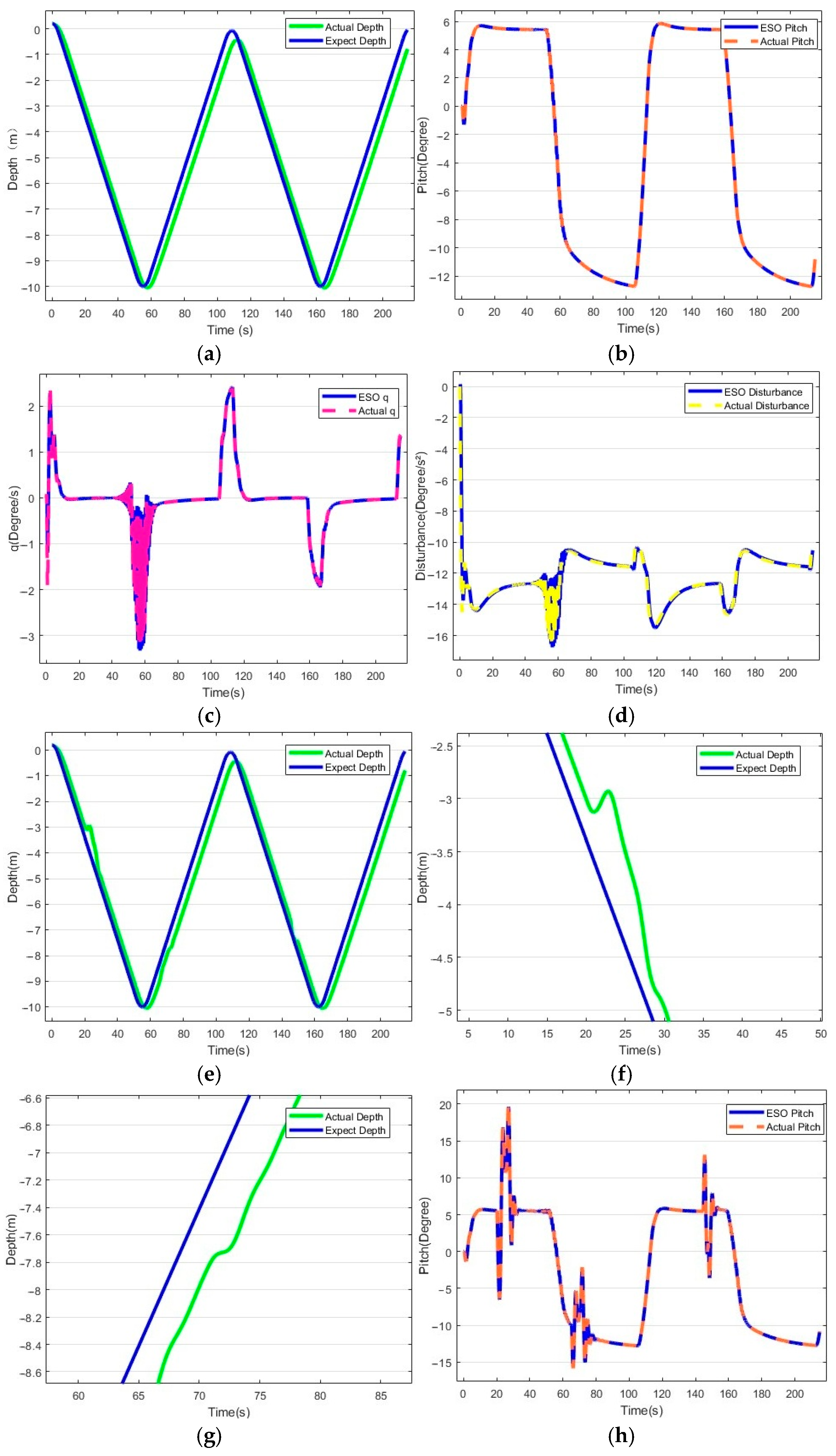
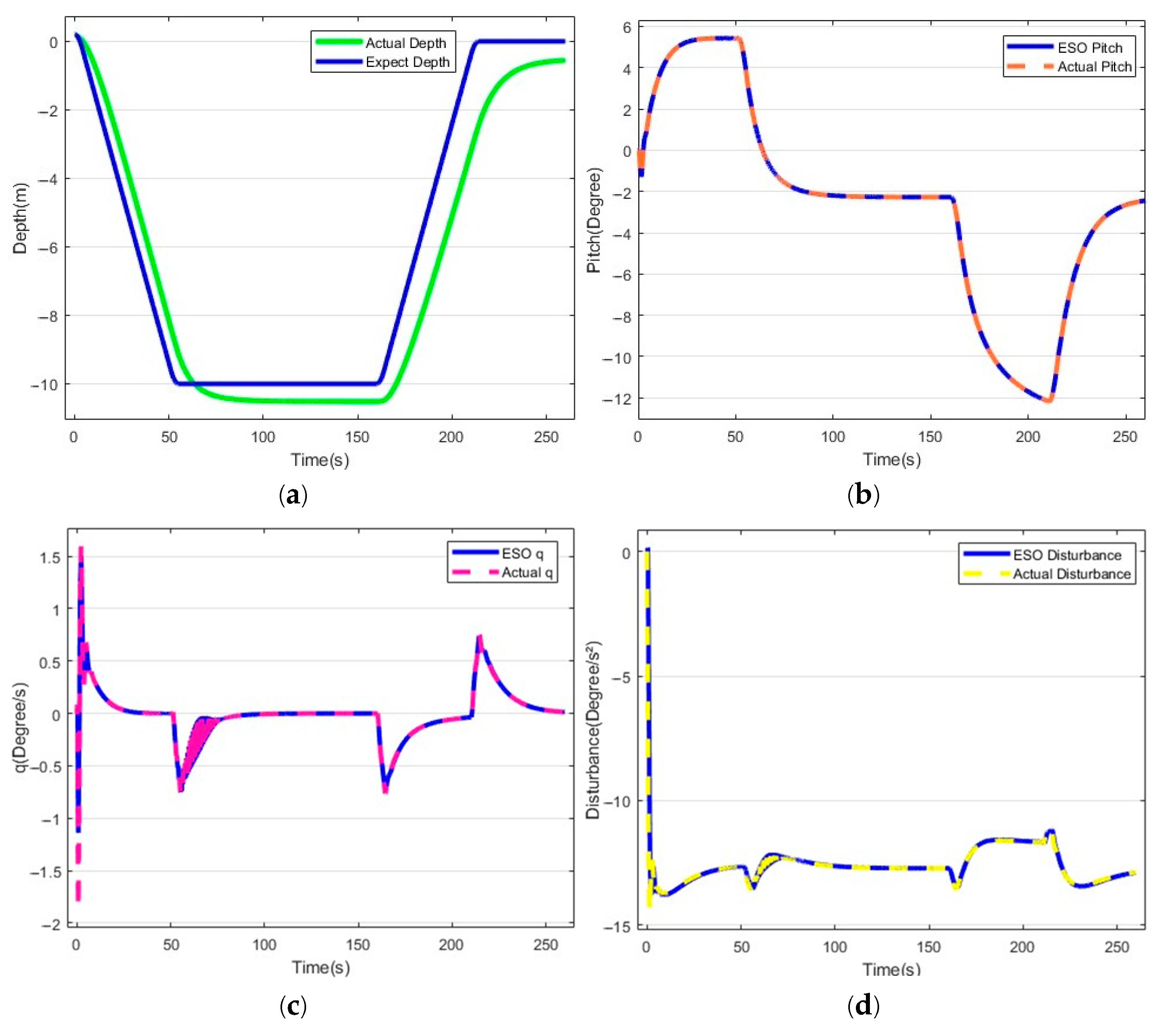
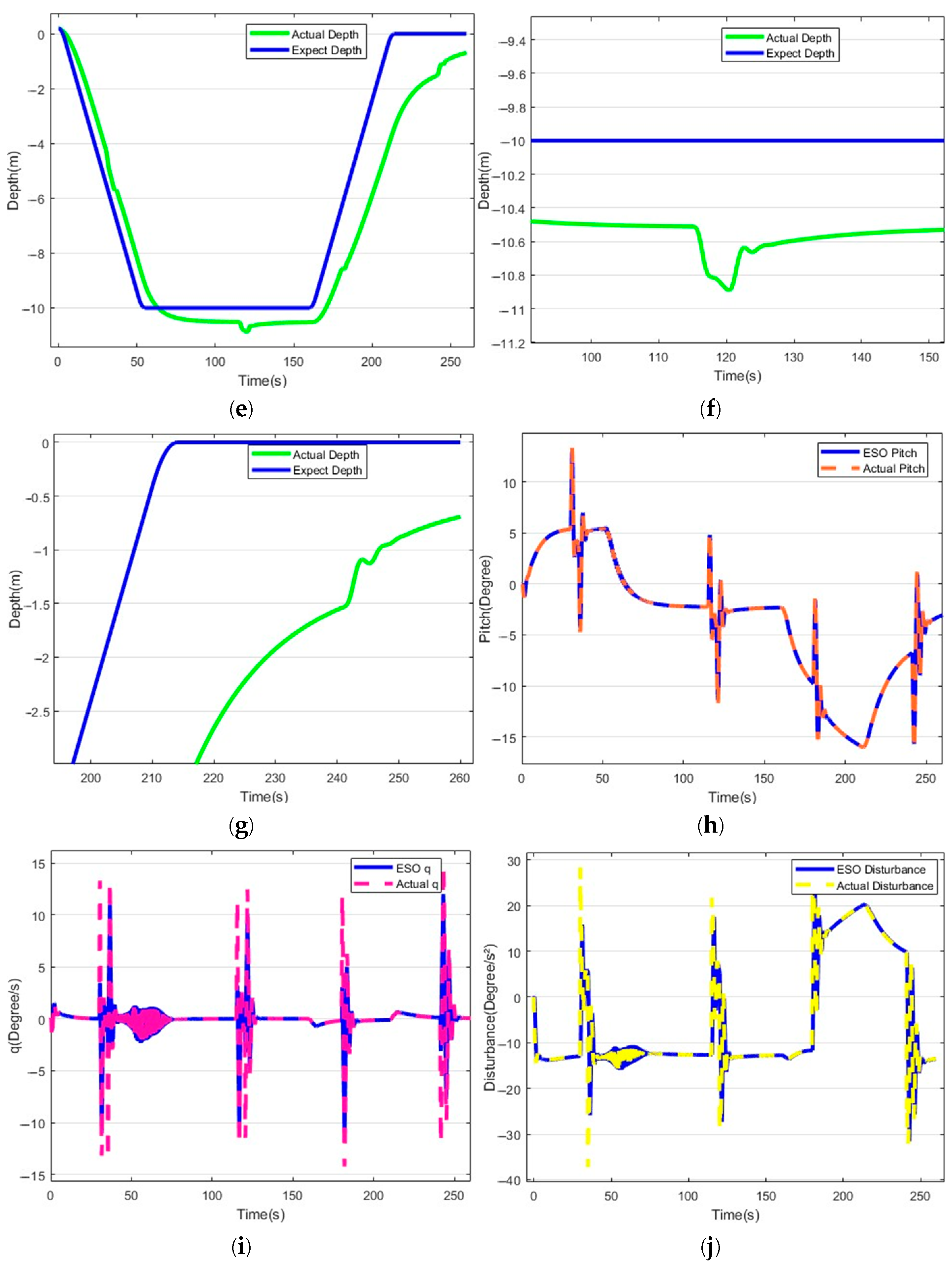
The results of the gliding mode motion test of the ADRC are shown in Figure 11. ADRC was able to reach the set depth in 59 s, with an error of 7 s from the expected requirement. However, during the ascent, the error in reaching the water surface was 0.5 m. This is due to the fact that during the motion of the HUG, the hydrostatic restoring torque and the dynamic restoring torque will increase, and the gradual accumulation of hydrodynamic error leads to the glider performing the next dive motion.
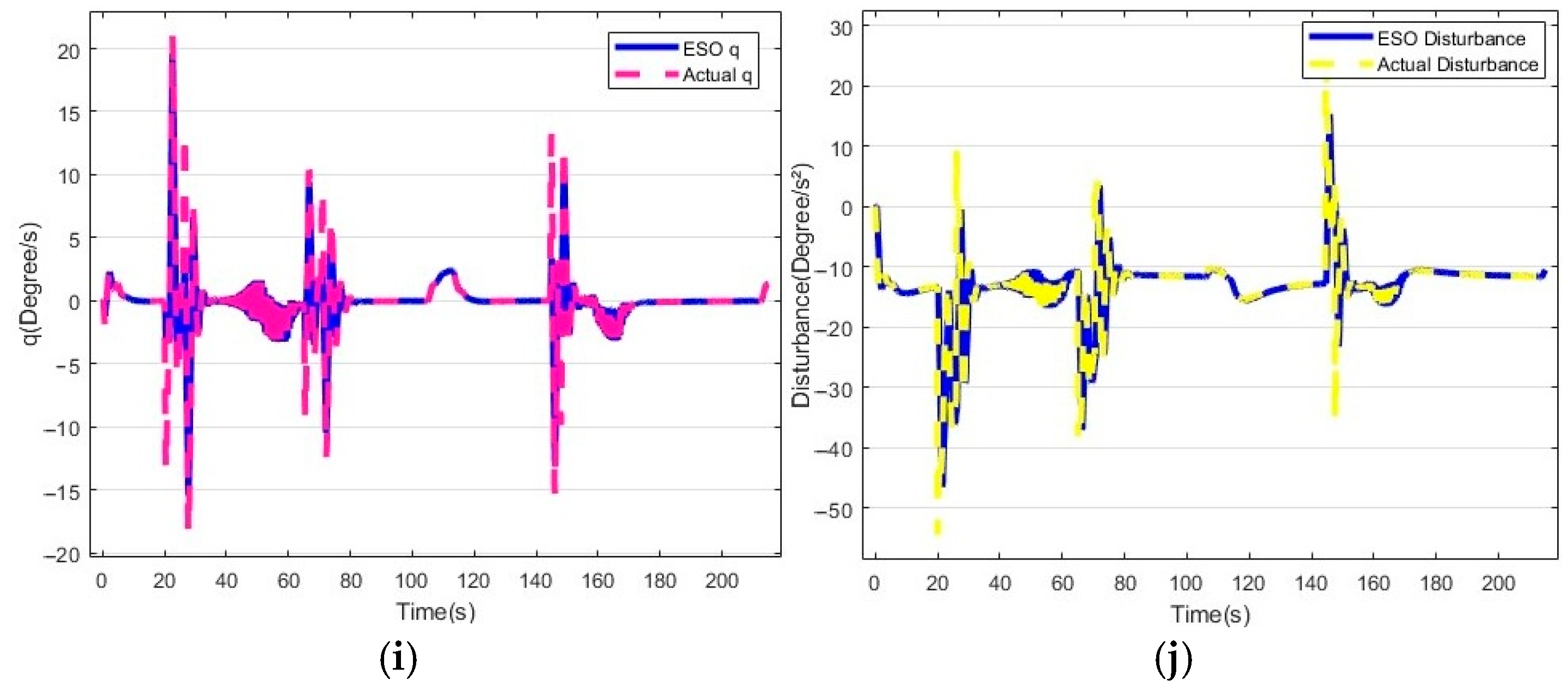
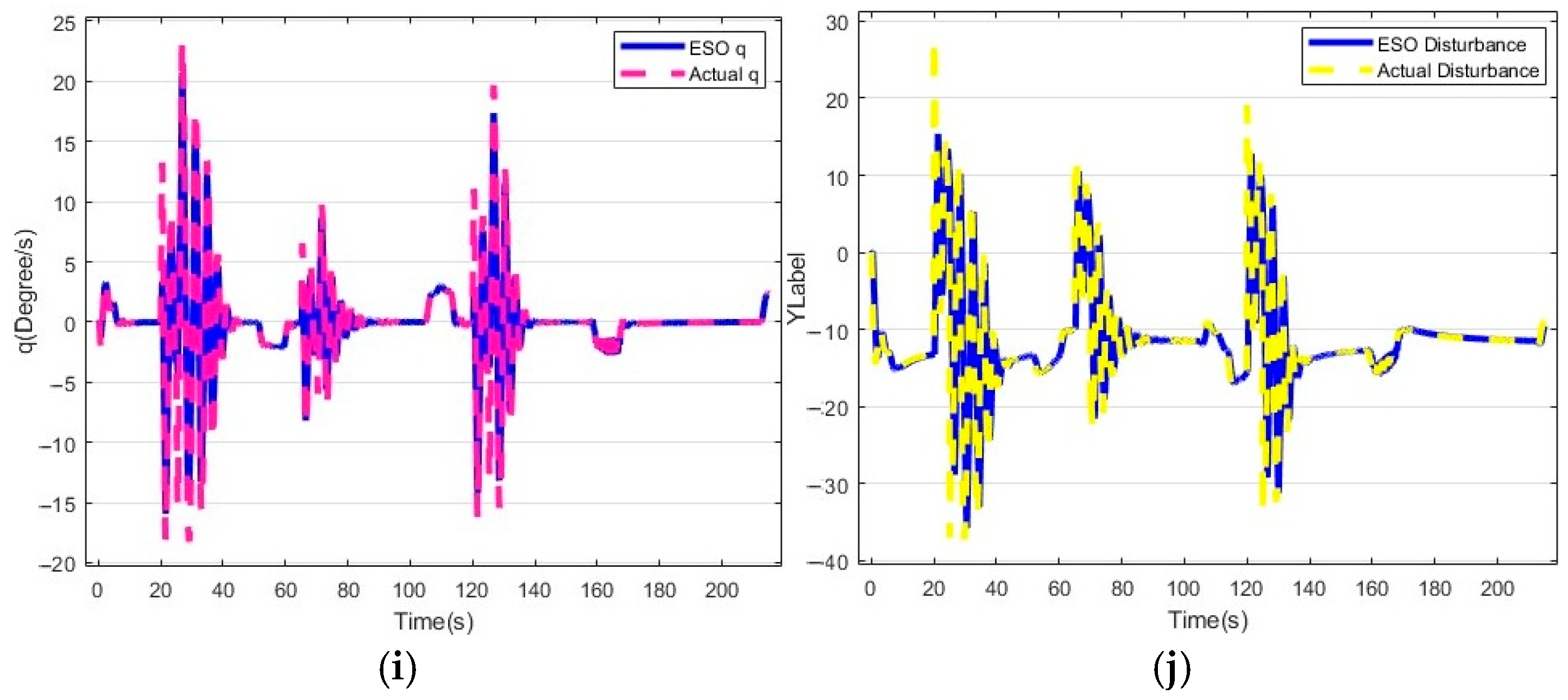
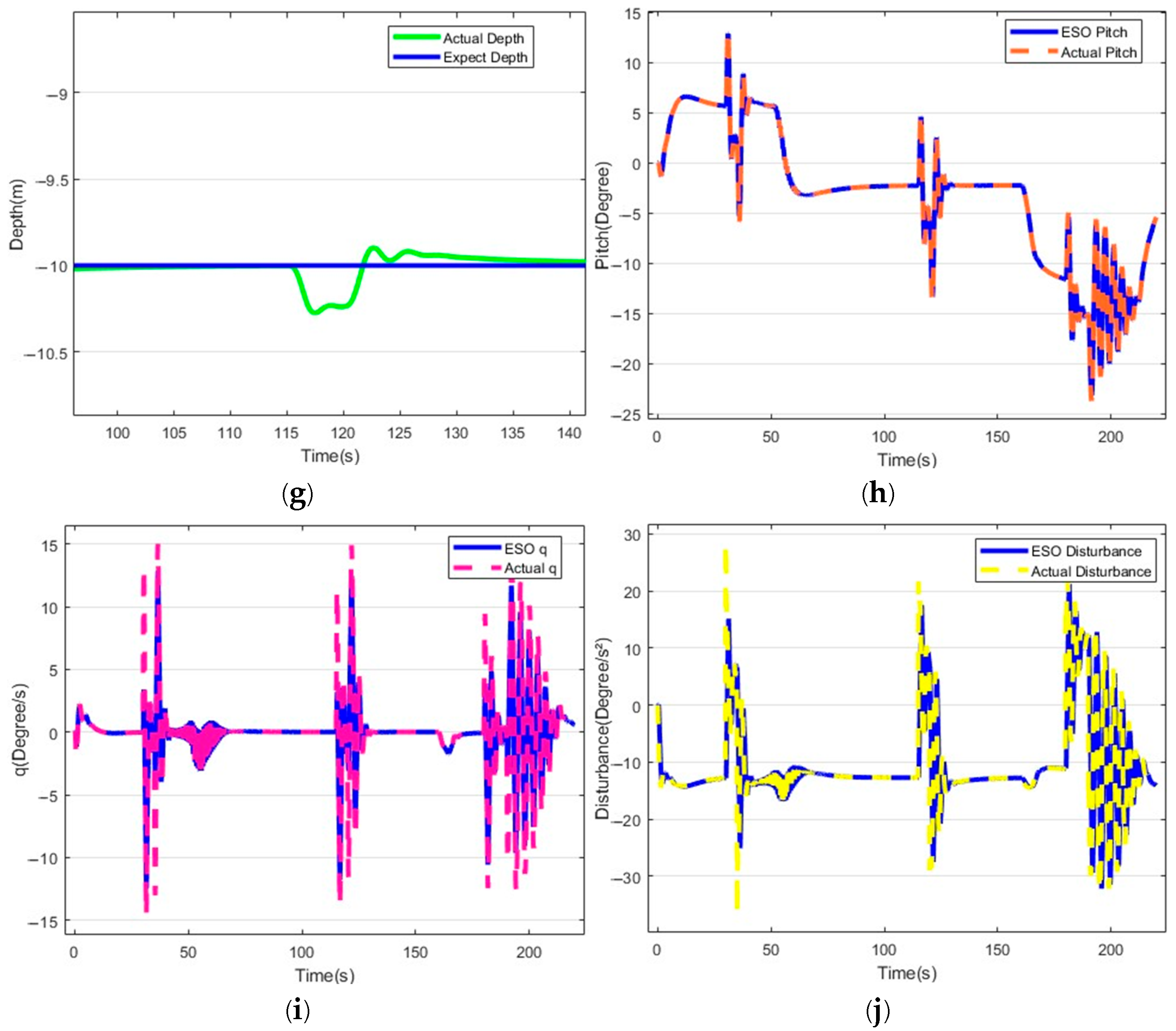
ESO, as the core of ADRC, demonstrates excellent estimation and compensation in the control. z 1 and z 2 estimate and compensate for pitch angle variations in real time, and the outputs agree with the actual θ and q . Gliders experience large attitude changes at the turning points of ascent and descent, and the z 3 can observe the total system perturbation changes in real time. The glider was deflected by the addition of the current perturbation, and z 3 observed changes in the perturbation of the system at 22 s, 66 s, and 143 s, respectively.
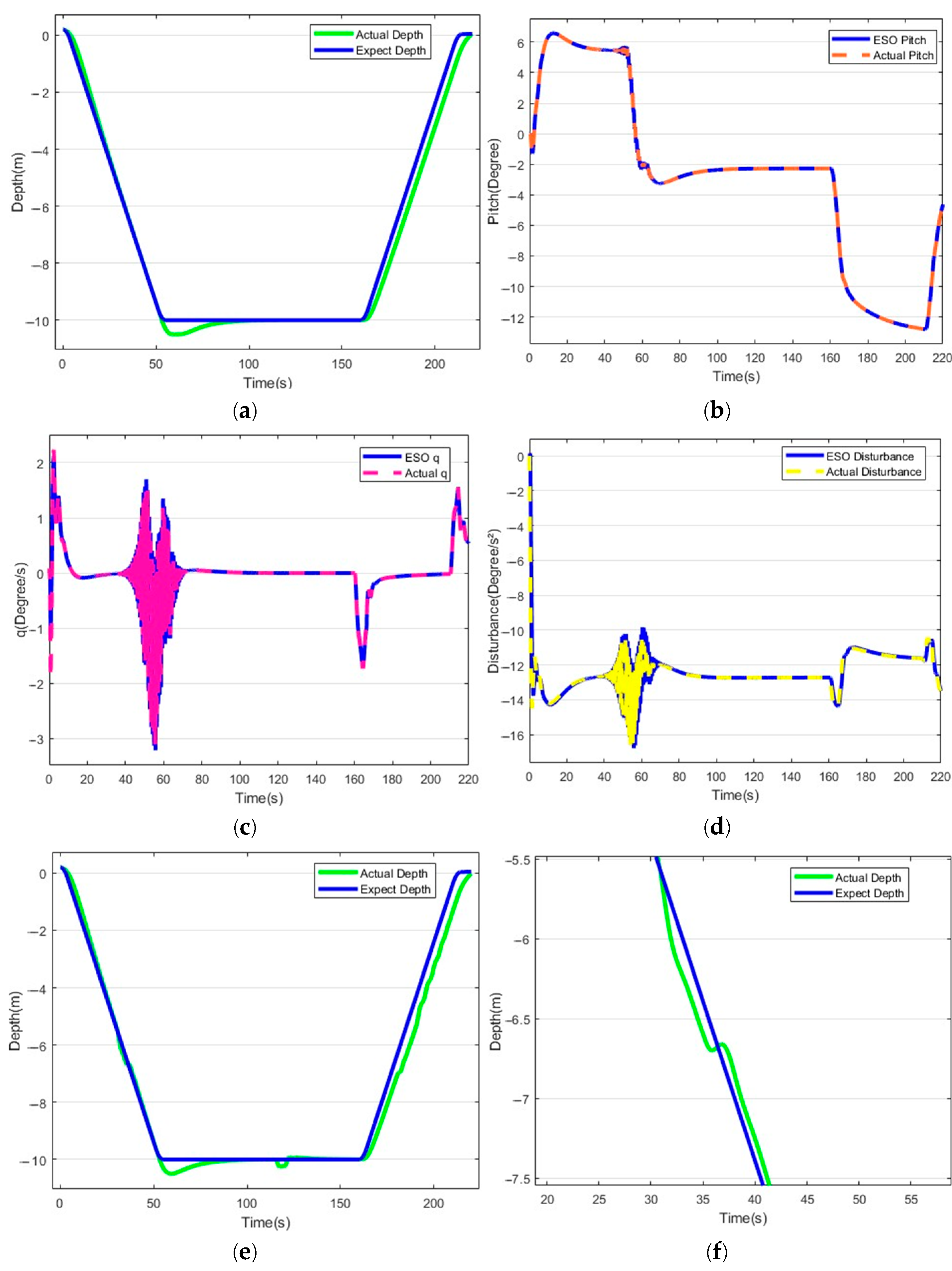
The results of the gliding mode motion test of OLOS-ADRC are shown in Figure 12. OLOS-ADRC is able to reach the set depth in 55 s, with an error of 3 s from the expected requirement. Because of the introduction of OLOS guidance, the whole HUG motion process is basically fitted with the expected depth control requirement, and at the same time, for the gradual accumulation of hydrodynamic error, the correction can be completed to ensure that the HUG can be exposed to the water surface to complete the communication. Meanwhile, z 1 and z 2 are able to estimate and compensate for pitch angle changes in real time in a way that is consistent with θ and q , demonstrating the dynamic convergence capability of the ADRC. HUG has demonstrated a perturbation adjustment capability in OLOS-ADRC that is superior to that of ADRC. z 3 observed the perturbation changes in the system at 20 s, 71 s, and 125 s, respectively, while compensating adjustments were made quickly.
At W = 0.3   m / s , OLOS-ADRC maintains depth errors < 0.1 m despite currents, leveraging the adaptive λ in Formula 17. This outperforms ADRC (errors > 0.4 m), confirming λ ’s role in enhancing low-velocity sensitivity—critical for glider missions in stratified flows.
The comparative analysis shows that ADRC is able to fulfill the control requirements of the specified depth. It is able to make adjustments when there are disturbances, thanks to the excellent anti-disturbance of ADRC. OLOS-ADRC arrives at the specified depth 3 s faster than ADRC, and it is worth noting that OLOS-ADRC not only accomplishes the depth requirement more accurately, but also ensures the return requirement of the HUG. Both in terms of stabilization time, steady state error, and anti-disturbance adjustment, OLOS-ADRC has better control performance than ADRC in both undisturbed and disturbed cases. Table 2 gives the values of ADRC and OLOS-ADRC performance in conventional gliding motion.

5.2. Hybrid Drive Exercise Test

The hybrid drive motion is a HUG that first performs a dive at a specified depth, then sails at a fixed depth at this depth, and eventually returns. The control performance of ADRC and OLOS-ADRC is compared through the hybrid drive motion test. The test conditions are set as follows: HUG completes the dive to a depth of 10 m, sails at a fixed depth for a certain period of time, and then completes the return motion. The same non-disturbance control experiments and experiments with disturbances were conducted.
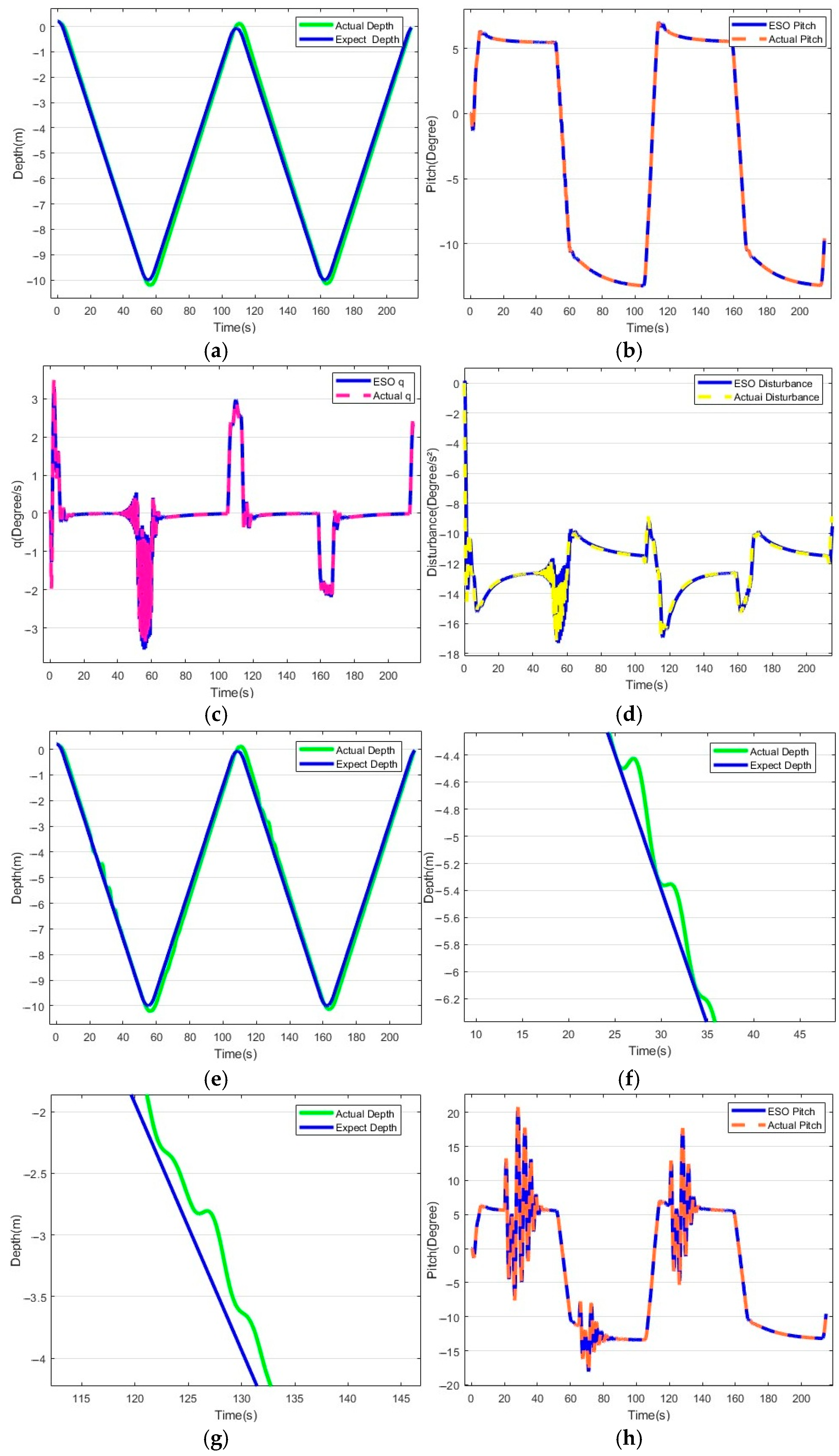
The results of the hybrid drive motion test of the ADRC are shown in Figure 13. The ADRC was able to reach the set depth in 59 s, with an error of 7 s from the expected requirement. Subsequent to the fixed-depth sailing, the HUG kept sailing around 10.6 m water depth, with an error of 0.6 m from the expected depth. This was due to the phenomenon of overshooting when descending to the specified depth, and continued sailing at the depth of the overshooting error after leveling off the attitude of the HUG. As the hydrostatic and dynamic recovery moments increase during the subsequent ascent, the error accumulates, causing the HUG to take a longer time to surface.
Observation of the ESO yields the contribution of the ADRC in accomplishing the desired movement, z 1 and z 2 accurately estimated and compensated for attitude angle control during the HUG transition attitude and were able to complete the dive to leveling to ascent, with z 3 observing system perturbation changes at 59 s and 162 s. When disturbance causes the HUG to shift, z 3 observes the disturbance appearing at 122 s and compensates in real time to bring the HUG back to sailing depth.
The results of the hybrid drive motion test of OLOS-ADRC are shown in Figure 14. OLOS-ADRC was able to reach the set depth in 51 s, and the error with the expected requirement was 1 s. The HUG also showed overshooting phenomenon after reaching the specified depth, and its attitude was adjusted when it dived down to 10.5 m. During the test, OLOS showed fast adjustment ability, and the HUG started to navigate at the set depth with an error of 0.1 m from the expected depth. In the ascent phase, the depth of HUG motion deviates from the expectation, which is due to the fact that when the fixed-depth navigation is converted to the ascent motion, the horizontal plane will have part of the inertial velocity of the forward motion, which leads to the deflection of the HUG. When a disturbance occurs in fixed-depth navigation, z 3 is able to observe and make compensatory adjustments in a timely manner, restoring the navigation depth after a 0.3 m adjustment.
The 10.5 m overshoot stems from inertial velocity coupling during glide-to-level transition. OLOS mitigates this by reducing Δ to 2 L, increasing desired pitch rate for faster correction.
The comparative analysis shows that ADRC is able to fulfill the hybrid drive control requirements. During the HUG attitude transition, the attitude angle can be adjusted in time, thanks to ADRC’s excellent and fast correction ability. The specified sailing depth error of OLOS-ADRC is 83% lower than that of the ADRC, while the adjustment speed is faster when switching to ascending motion, and the return time is shorter. The fixed depth sailing, anti-disturbance adjustment, and the return motion of OLOS-ADRC all show a better performance than ADRC. Table 3 gives the values of ADRC and OLOS-ADR braking performance in the hybrid drive motion.

6. Conclusions

In this paper, a new HUG longitudinal plane control method is proposed, and the superiority of the control method is highlighted by the conventional gliding motion simulation test and the mixed-drive motion simulation test. The method is based on ADRC and introduces the optimized LOS guidance technology, which transforms the depth tracking problem into pitch angle tracking, and obtains the OLOS-ADRC method. The method can automatically evaluate and adjust to the control parameters of ADRC, better adapting to the interference of the sea current.
In the tests of the two motion modes, both ADRC and OLOS-ADRC are able to fulfill the specified requirements, and the depth stabilization error of OLOS-ADRC is 0.2 m, which is significantly lower than that of ADRC. After the introduction of the disturbance of the ocean currents, the ADRC shows an excellent disturbance estimation and compensation adjustment ability, the introduction of the OLOS enhances the accuracy of the control, and the OLOS-ADRC has an excellent control performance and high adaptive capability.
The proposed OLOS-ADRC strategy not only improves depth tracking precision but also enhances energy efficiency during thermocline mapping missions. By reducing depth fluctuations and minimizing unnecessary control actions, the system decreases the frequency of buoyancy adjustments and thruster activations, primarily due to smoother pitch transitions and reduced overshooting. This energy saving translates directly to extended mission duration or increased sensor operational time, particularly valuable for long-term oceanographic observations.
While pool tests provided valuable data for model calibration, they cannot fully replicate open-ocean conditions, such as stratified currents or waves. Future sea trials will be conducted to validate the method in real environments. In the future work, we will establish a more accurate dynamic model of HUG and further improve the stability of the control structure at all levels of OLOS-ADRC. We simulated OLOS-ADRC in 3D waypoint tracking using coupled yaw–pitch dynamics. We replaced LOS with 3D vector guidance and augmented ESO to estimate roll–yaw disturbances.

Author Contributions

Y.Z. (Yan Zhao): Co-first author, Conceptualization, Data curation, Investigation, Software, Validation, Writing—original draft, Writing—review and editing. H.Z.: Co-first author, Visualization, Validation, Software, Methodology, Formal analysis, Conceptualization. P.X.: Validation, Project administration, Conceptualization. Y.J.: Writing—review and editing, Supervision, Resources, Funding acquisition, Conceptualization. Z.T.: Validation, Project administration, Conceptualization. Y.Z. (Yun Zhao): Writing—review and editing, Methodology, Conceptualization. All authors have read and agreed to the published version of the manuscript.

Funding

This work is supported by Innovation Fund Project for Independent Research of National University of Defense Technology (Grant No. 25-ZZCX-JDZ-56), the National Key Research and Development Program of China (Grant No. 2022YFC2805904) and the Science and Technology Innovation Program of Hunan Province (Grant No. 2023ZJ1020, 2024AQ2031).

Data Availability Statement

The original contributions presented in the study are included in the article material. Further inquiries can be directed to the corresponding author.

Conflicts of Interest

The authors declare no conflicts of interest. The funders had no role in the design of the study, data collection, analyses, and interpretation, writing of the manuscript, and decision to publish the results.

References

  1. Li, J.; Li, W.; Liu, Q.; Luo, B.; Cui, W. Current Status and Technical Challenges in the Development of Biomimetic Robotic Fish-Type Submersible. Ocean-Land-Atmos. Res. 2024, 3, 0036. [Google Scholar] [CrossRef]
  2. Webb, D.C.; Simonetti, P.J.; Jones, C.P. SLOCUM: An underwater glider propelled by environmental energy. IEEE J. Ocean. Eng. 2001, 26, 447–452. [Google Scholar] [CrossRef]
  3. Eriksen, C.C.; Osse, T.J.; Light, R.D.; Wen, T.; Lehman, T.W.; Sabin, P.L.; Ballard, J.W.; Chiodi, A.M. Seaglider: A long-range autonomous underwater vehicle for oceanographic research. IEEE J. Ocean. Eng. 2001, 26, 424–436. [Google Scholar] [CrossRef]
  4. Wang, Y.; Wang, C.; Yang, M.; Liang, Y.; Han, W.; Yang, S. Glide performance analysis of underwater glider with sweep wings inspired by swift. Front. Mar. Sci. 2022, 9, 1048328. [Google Scholar] [CrossRef]
  5. Chu, F.S.; Si, Z.S.; Pang, C.G.; Yu, J.C. Thermal Lag Correction From a GLIDER Payload CTD for Poor Temperature Data. Pure Appl. Geophys. 2020, 177, 3039–3051. [Google Scholar]
  6. Liu, Z.; Xu, J.; Yu, J. Real-time quality control of data from Sea-Wing underwater glider installed with Glider Payload CTD sensor. Acta Oceanol. Sin. 2020, 39, 134–144. [Google Scholar]
  7. Zhou, H.; Zeng, Z.; Yu, C.; Yao, B.; Lian, L. Adaptive robust sliding mode control of autonomous underwater glider with input constraints for persistent virtual mooring. Appl. Ocean Res. 2020, 95, 102027. [Google Scholar]
  8. Wang, Y.; Guo, Y.; Yang, S.; Sun, T.; Wang, X.; Zhou, H. Design, Hydrodynamic Analysis, and Testing of a Bio-inspired Movable Bow Mechanism for the Hybrid-driven Underwater Glider. J. Bionic Eng. 2023, 20, 1493–1513. [Google Scholar]
  9. Eichhorn, M. Optimal Routing Strategies for Autonomous Underwater Vehicles in Time-Varying Environment. Robot. Auton. Syst. 2015, 67, 33–43. [Google Scholar] [CrossRef]
  10. Zhou, M.; Bachmayer, R.; Deyoung, B. Surveying a Floating Iceberg with the USV SEADRAGON. Front. Mar. Sci. 2021, 8, 549566. [Google Scholar] [CrossRef]
  11. Zhang, Y.; Hobson, B.W.; Kieft, B.; Godin, M.A.; Ravens, T.; Ulmgren, M. Adaptive Zigzag Mapping of a Patchy Field by a Long-Range Autonomous Underwater Vehicle. IEEE J. Ocean. Eng. 2024, 49, 403–415. [Google Scholar] [CrossRef]
  12. Yang, Y.; Liu, Y.; Wang, Y.; Zhang, H.; Zhang, L. Dynamic modeling and motion control strategy for deep-sea hybrid-driven underwater gliders considering hull deformation and seawater density variation. Ocean Eng. 2017, 143, 66–78. [Google Scholar] [CrossRef]
  13. Yang, C.; Peng, S.; Fan, S. Performance and Stability Analysis for ZJU Glider. Mar. Technol. Soc. J. 2014, 48, 88–103. [Google Scholar] [CrossRef]
  14. Isa, K.; Arshad, M.R.; Ishak, S. A hybrid-driven underwater glider model, hydrodynamics estimation, and an analysis of the motion control. Ocean Eng. 2014, 81, 111–129. [Google Scholar] [CrossRef]
  15. Liu, F.; Lan, T.; Wei, Z.; Sun, X.; Zhang, S.; Sang, H.; Huang, F. Adaptive propeller rudder controller for the wave glider with a propeller-rudder control system. Ocean Eng. 2023, 289, 116129. [Google Scholar] [CrossRef]
  16. Fan, S.S.; Yang, C.J.; Peng, S.L.; Li, K.H.; Xie, Y.; Zhang, S.Y. Underwater glider design based on dynamic model analysis and prototype development. J. Zhejiang Univ. Sci. C 2013, 14, 583–599. [Google Scholar] [CrossRef]
  17. Bhatta, P.; Leonard, N.E. Nonlinear gliding stability and control for vehicles with hydrodynamic forcing. Automatica 2008, 44, 1240–1250. [Google Scholar] [CrossRef]
  18. Su, Z.Q.; Zhou, M.; Han, F.F.; Zhu, Y.W.; Song, D.L.; Guo, T.T. Attitude control of underwater glider combined reinforcement learning with active disturbance rejection control. J. Mar. Sci. Technol. 2019, 24, 686–704. [Google Scholar] [CrossRef]
  19. Zhou, H.; Fu, J.; Zeng, Z.; Yu, C.; Wei, Z.; Yao, B.; Lian, L. Adaptive robust tracking control for underwater gliders with uncertainty and time-varying input delay. Ocean Eng. 2021, 240, 109945. [Google Scholar] [CrossRef]
  20. Caharija, W.; Pettersen, K.Y.; Gravdahl, J.T.; Børhaug, E. Integral LOS guidance for horizontal path following of underactuated autonomous underwater vehicles in the presence of vertical ocean currents. In Proceedings of the American Control Conference (ACC), Maui, HI, USA, 10–13 December 2012. [Google Scholar]
  21. Zhang, H. An Improved ELOS Guidance Law for Path Following of Underactuated Unmanned Surface Vehicles. Sensors 2024, 24, 5384. [Google Scholar]
  22. Xiu, Y.; Li, D.; Zhang, M.; Deng, H.; Law, R.; Huang, Y.; Wu, E.Q.; Xu, X. Finite-Time Sideslip Differentiator-Based LOS Guidance for Robust Path Following of Snake Robots. IEEE/CAA J. Autom. Sin. 2023, 10, 239–253. [Google Scholar] [CrossRef]
  23. Lefeber, E.; Pettersen, K.Y.; Nijmeijer, H. Tracking control of an underactuated ship. IEEE Trans. Control Syst. Technol. 2003, 11, 52–61. [Google Scholar] [CrossRef]
  24. Fossen, T.I.; Lekkas, A.M. Direct and indirect adaptive integral line-of-sight path-following controllers for marine craft exposed to ocean currents. Int. J. Adapt. Control Signal Process. 2017, 31, 445–463. [Google Scholar] [CrossRef]
  25. Leonard, N.E. Model-Based Feedback Control of Autonomous Underwater Gliders. IEEE J. Ocean. Eng. 2001, 26, 633–645. [Google Scholar] [CrossRef]
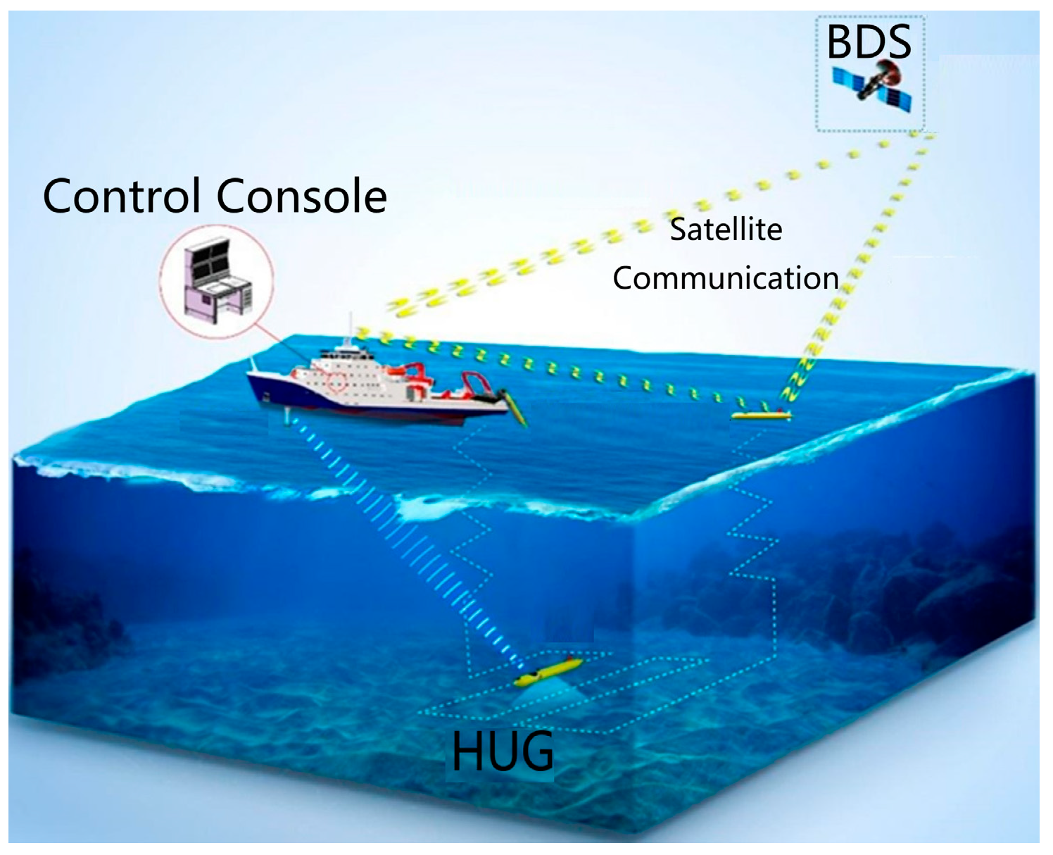
Figure 1. Hybrid-driven underwater glider motion form.
Jmse 13 01835 g001
Figure 2. HUG structure layout.
Jmse 13 01835 g002
Figure 3. Hybrid-driven underwater glider mass plot.
Jmse 13 01835 g003
Figure 4. Definition of coordinate system and force analysis.
Jmse 13 01835 g004
Figure 5. Principle of LOS guidance.
Jmse 13 01835 g005
Figure 6. Sensitivity Analysis.
Jmse 13 01835 g006
Figure 7. Comparison of signal tracking characteristics between TD and TSTD.
Jmse 13 01835 g007
Figure 8. Principle of OLOS-ADRC.
Jmse 13 01835 g008
Figure 9. HUG physical vehicle.
Jmse 13 01835 g009
Figure 10. The actual ocean currents at different depths.
Jmse 13 01835 g010
Figure 11. ADRC conventional gliding motion. (a) Non-disturbance gliding depth tracking, (bd) Non-disturbance ESO observed result, (eg) Deep tracking under disturbance, (hj) ESO observed result under disturbance. (a) For unperturbed depth tracking, (e) for depth tracking under perturbation, (f,g) for perturbation adjustment, and (bd,hj) for ESO observation comparisons.
Jmse 13 01835 g011aJmse 13 01835 g011b
Figure 12. Conventional gliding motion of OLOS-ADRC. (a) Non-disturbance gliding depth tracking, (bd) Non-disturbance ESO observed result, (eg) Deep tracking under disturbance, (hj) ESO observed result under disturbance.
Jmse 13 01835 g012aJmse 13 01835 g012b
Figure 13. ADRC hybrid drive movement. (a) Non-disturbance gliding depth tracking, (bd) Non-disturbance ESO observed result, (eg) Deep tracking under disturbance, (hj) ESO observed result under disturbance.
Jmse 13 01835 g013aJmse 13 01835 g013b
Figure 14. OLOS-ADRC hybrid drive movement. (a) Non-disturbance gliding depth tracking, (bd) Non-disturbance ESO observed result, (eg) Deep tracking under disturbance, (hj) ESO observed result under disturbance.
Jmse 13 01835 g014aJmse 13 01835 g014b
Table 1. HUG parameters.
NameNumerical
length1.8 m
m h 45 kg
m f 1 15 kg
m f 3 20 kg
ρ 1025 kg/m3
Δ min 3.6 m
Δ max 10.8 m
Table 2. Comparison of ADRC and OLOS-ADRC performance for conventional gliding sports.
Performance IndexADRCOLOS-ADRC
TimeError7 s3 s
DepthError−0.5 m0.2 m
Attitude Angle errorUndisturbed3.1°2.1°
Disturbed4.5°3.3°
Table 3. Comparison of ADRC and OLOS-ADRC performance for hybrid drive motion.
Performance IndexADRCOLOS-ADRC
TimeError7 s1 s
Depth keepingError0.6 m0.1 m
Disturbed adjustment Length0.5 m0.3 m
Disclaimer/Publisher’s Note: The statements, opinions and data contained in all publications are solely those of the individual author(s) and contributor(s) and not of MDPI and/or the editor(s). MDPI and/or the editor(s) disclaim responsibility for any injury to people or property resulting from any ideas, methods, instructions or products referred to in the content.