Article

Investigation on Low-Frequency and Broadband Sound Absorption of the Compact Anechoic Coating Considering Hydrostatic Pressure

1
National Key Laboratory on Ship Vibration and Noise, China Ship Scientific Research Center, Wuxi 214082, China
2
Department of Basic Science and Technology Research, Taihu Laboratory of Deepsea Technological Science, Wuxi 214082, China
3
School of Aerospace Engineering and Applied Mechanics, Tongji University, Shanghai 200092, China
4
Shanghai Key Laboratory of Intelligent Sensing and Detection Technology, School of Mechanical and Power Engineering, East China University of Science and Technology, Shanghai 200237, China
*
Authors to whom correspondence should be addressed.
These authors contributed equally to this work.
J. Mar. Sci. Eng. 2024, 12(4), 543; https://doi.org/10.3390/jmse12040543
Submission received: 21 February 2024 / Revised: 20 March 2024 / Accepted: 22 March 2024 / Published: 25 March 2024
(This article belongs to the Section Ocean Engineering)

Abstract

:
The anechoic coating capable of absorbing sound energy in low frequencies within broadband is essential to conceal underwater vehicles. However, the geometric deformation and modification of mechanical parameters under hydrostatic pressure affect the prediction of absorption performance in deep water environments. An anechoic coating embedded with tandem resonant voids is proposed in this work to achieve quasi-perfect low-frequency and broadband absorption. The analytical method based on the effective medium approach and numerical simulation are performed to estimate the effects of hydrostatic pressure on sound absorption. When additionally considering the dynamic mechanical parameters of the compressed viscoelastic medium, the original absorption humps in low frequencies are inclined to higher band, accompanied by the expanded absorption bandwidth. Then, the tandem coating specimen is measured in a water-filled impedance tube. The experimental spectra are consistent with the analytical and numerical results under various hydrostatic pressures, demonstrating the efficient absorption (α > 0.7) in broadband low frequencies via ordinary pressure. At the same time, the absorption spectrum under higher hydrostatic pressures is also verified in the tube. Consequently, this work paves the way for a broadband low-frequency underwater absorber design and provides an efficient method to characterize the low-frequency and broadband absorption from the coupled resonant coatings in deep water environments.

1. Introduction

As a crucial scheme to shield the active sonar detection signal and to suppress the echo from hulls, anechoic coatings have significantly improved the comprehensive stealth performance of underwater vehicles [1,2,3]. The traditional layer was made of viscoelastic material as the host medium to match their surface impedance with the background, and sundry embedded cavities were introduced to improve the underwater absorption in low frequencies [4,5,6]. Such configuration enhanced the wave-type conversion from scattering waves inside coatings [7] as the incident wave approached the embedded voids’ resonant frequency. Thus, the energy dissipation in low frequencies occurred based on viscous friction, heat conduction, and the substrate relaxation [4,8]. At present, viscoelastic medium embedded with periodic voids is still the efficient type of anechoic coatings laid on vehicles. Among previous studies, an analytical solution based on the viscoelastic Kelvin–Voigt theory [1] was proposed, which accounted for the dispersion curves and attenuation of the axisymmetric viscoelastic waves in perforated neoprene [9,10]. Then, the effective medium approach (EMA) for the anechoic coatings embedded with penetrating voids was proposed based on the monopole resonance effect [6,9]. In such an artificial microstructure, the insulation bandwidth could be tuned precisely associated with the geometric parameters of the periodic voids [10].
The anechoic coating affixed to submarine surface is expected to play an efficient role in absorbing soundwaves in tens or even hundreds of meters in water, guaranteeing underwater vehicles’ fighting power and vitality. Nevertheless, dramatic changes behind the geometry of embedded voids and the mechanical parameters would occur associated with the hydrostatic pressures, resulting in a surprising discrepancy in the surface impedance compared with the atmosphere [7,11,12,13,14,15]. Previous researchers have revealed experimental effects of hydrostatic pressure on coating’s behavior [11,15], but theoretical prediction and physical mechanisms have not been investigated sufficiently. For the anechoic layer embedded with air-filled voids, configuration deformation of the single-layer cavities in various submerged depth [16,17] was calculated numerically in finite element (FE) simulation. Determining how to reduce the modeling error for the tandem coating embedded with coupling resonant voids needs further research because the voids deformation is irregular after extrusion [18]. This work will introduce the analytical model of tandem-voids resonant coatings based on EMA, then it will propose an optimized underwater absorber in broadband and low frequencies. The acoustic performance variation considering hydrostatic pressures will be discussed by considering the irregular geometric deformation and the incremental mechanical parameters of the host medium. In addition, the experiment will be conducted in an impedance tube filled with water, to verify the absorption performance in wide, low frequencies and the corresponding evolution of this tandem coating under hydrostatic pressures.

2. Method and Model

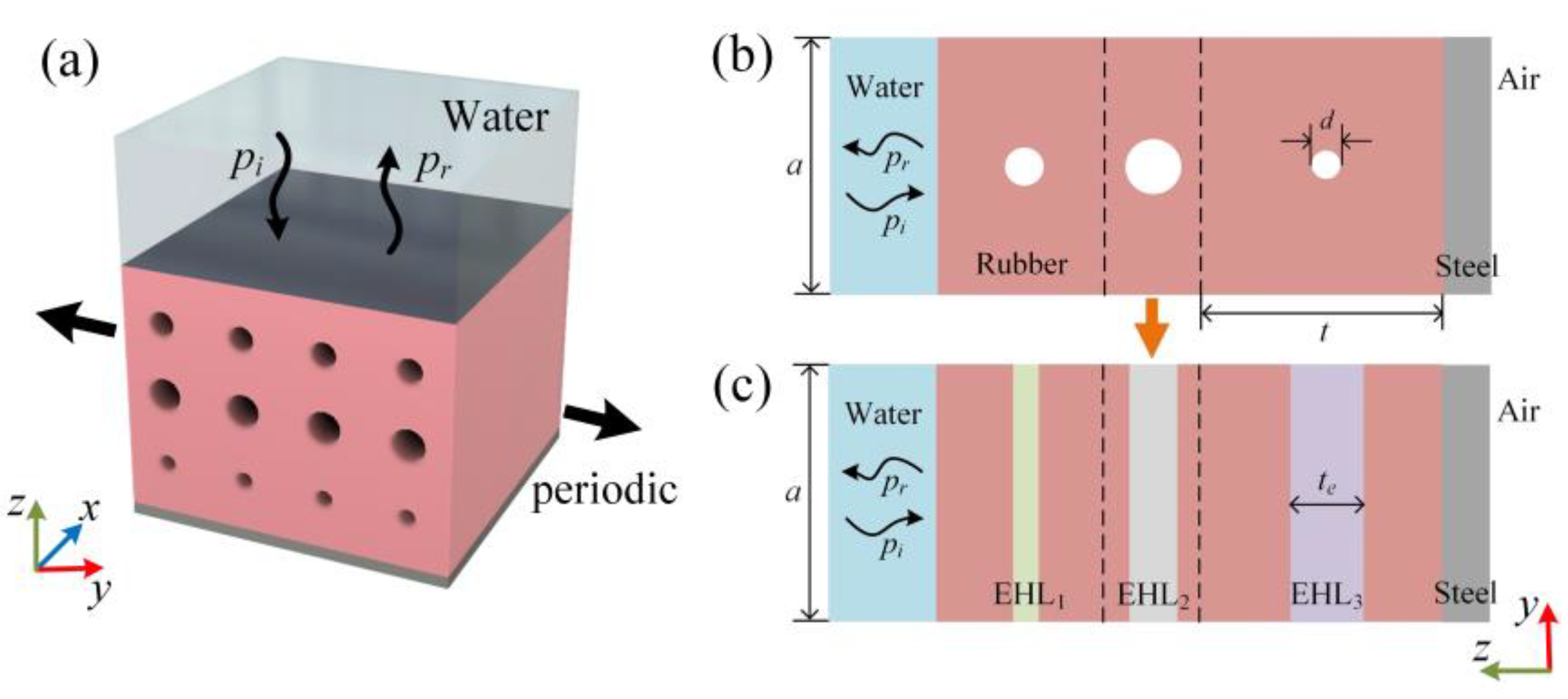
2.1. Model of the Compact Anechoic Coating

The schematic diagram of the proposed anechoic coating, which consists of multilayer perforative cylindrical voids, is presented in Figure 1a. Such scatters periodically disperse in the host medium in the y-direction while extending infinitely in the x-direction. When the sound waves incident into the surface perpendicularly, they travel through the water domain, host medium embedded with tandem voids, steel backing, and air domain successively. Viscoelastic material such as rubber was generally adopted as the host medium for the impedance matching with the water domain and the resultful shear losses [19,20]. The cross-section diagram of the multilayer coating is shown in Figure 1b, in which the different diameters of tandem perforative voids and heights of rubber layers determine the surface impedance precisely [21]. Water density and sound speed are ρ w = 1000   k g / m 3 ,   c w = 1500   m / s , while those of air are ρ a = 1.2   k g / m 3 ,     c a = 340   m / s . The mechanical parameters of the solid material are listed in Table 1.
The heterogeneous viscoelastic material, such as the rubber embedded with the tandem resonant voids, could be simplified into several homogeneous media associated with various effective impedance Z e = ρ e c e [22], as shown in Figure 1c. ρ e and c e are the effective density and velocity in each layer, respectively. The representation of ρ e was obtained as ρ e = ρ 1 α t t e [9,23], which is derived from the global homogenization of the voided medium as the global effective density ρ o = ρ 1 α , while ρ is the density of the host medium, α = π d 2 4 a 2 refers to the filling factor of the voids in each layer, d and a represent the diameter and distribution period of the inside voids, and t is the height of each layer. For the viscoelastic medium embedded with penetrating cylindrical cavities, the equivalent thickness of EHL is t e = 2 a π l n δ 2 + 1 2 δ , and δ = t a n π a d 4 a [9,24]. The equivalent longitudinal modulus could be simplified as κ e = κ o κ t e / κ t t t e κ o [9]; here, κ is the longitudinal modulus of rubber and κ o = κ 1 α 1 + α κ / μ 1 ω / Ω 0 2 1 [25,26]. μ refers to the value of shear modulus. In order for the longitudinal modulus to be determined by the coating configuration and the resonant frequency Ω 0 of the perforative void array, as the shear wave speed is much smaller than the longitudinal speed, Ω 0 = ω 0 1 d / a 2 0.03 l n a / d could be represented in the viscoelastic medium [10,27], i.e., the rubber mentioned in Table 1. ω 0 refers to the resonant frequency of the independent cavity in the infinite rubber substrate. Moreover, it could be expressed as ω 0 = 4 d μ / ρ l n 4 κ / μ / q 2 when the longitudinal wavelength k l   satisfies k l d / 2 1 [23]. Here, μ = μ + i μ is the complex shear modulus in rubber, and q 1.78 is the Euler’s constant.
The equivalent velocity c e in the effective homogeneous layer (EHL) could then be calculated logically upon the above homogenization. Following the transfer matrix method [21,28,29,30], the transitive relation between complex pressure and normal velocity satisfies P A ; V A = T P B ; V B , and the subscripts A and B indicate the incident (water) and transmitted (air) domain, respectively. T is the transfer matrix, represented as
T = T 11 T 12 T 21 T 22 = c o s k 1 t 1 j Z 1 s i n k 1 t 1 j Z 1 s i n k 1 t 1 c o s k 1 t 1   · c o s k 2 t 2 j Z 1 s i n k 2 t 2 j Z 2 s i n k 2 t 2 c o s k 2 t 2 c o s k 3 t 3 j Z 1 s i n k 3 t 3 j Z 3 s i n k 3 t 3 c o s k 3 t 3 .
Here, k n ,     t n ,   Z n   n = 1,2 , 3 refer to the equivalent wavelength, thickness, and impedance in each EHL, respectively.
Owing to the impedance mismatching between steel backing and air, the surface impedance of the tandem coating can be expressed as Z s = P A / V A = T 12 / T 22 . Then, the absorption coefficient can be obtained as
α = 1 Z s Z w Z s + Z w 2 ,
where Z w = ρ w c w is the characteristic impedance of water.
The absorption spectrum can be deduced from Equation (2) with the determined geometric and mechanical parameters of layers. In order to propose the underwater absorber suitable for the target low frequencies, a genetic algorithm (GA) in concert with the above method is utilized here. As an optimization algorithm inspired by biological evolution and natural selection, the flowchart of the GA is depicted in Figure 2. In the optimization, the crossover and mutation probability constant, population size, and maximum iteration generation were set as 0.2, 0.2, 100, and 10,000, respectively. Because the broadband absorption for sonar signals at low frequencies is important to improve the stealth performance of underwater vehicles, the tandem coating embedded with multilayer voids would be further designed via GA, so that the objective function is set as O b j e c t i v e = 1 N n = 1 N 1 α f n with the working frequency f n n = 1 , , N . Here, N is equal to the layer number of the tandem coating. The global optimized geometric parameters, including a, d, and t, can then be pinpointed when the termination condition is satisfied. The total number of variables to be optimized is 3*N. Note that d < t and d < a are set to guarantee the reality in geometry. In addition, π d > a should be included in the search-bounded constraints to ensure the resonant frequency Ω 0 limited in the EMA method [23]. In the GA optimization, there are two types of the termination conditions. One is reaching the maximum iteration generation. The other is solution convergence, which means no significant individual improvement over the past few generations. Here, the objective function is regarded as the screening criterion for individual fitness, as represented in Figure 2. We compare the current best fitness value with the mean fitness value from the past few generations, and if the difference is less than the threshold ( 1   ×   10 5 set in the algorithm), the solution is considered to be convergent. Based on this, we could come up with quasi-perfect waterborne absorbers pertinently on the low frequencies and broadband via compact sizes.

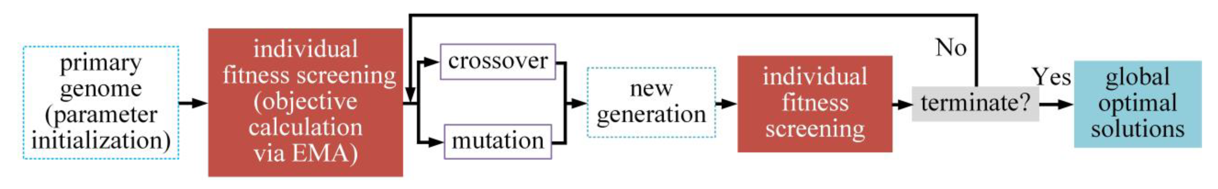
2.2. Analysis Procedure about the Geometric Deformation

To mimic the affected absorption performance of the anechoic coating under hydrostatic pressures, the resonant voids’ deformation in the host medium will be analyzed in this paper, as follows. Figure 3 represents the flow chart for absorption performance estimation via hydrostatic pressure. The finite element simulation is performed to calculate the steady irregular deformation of the anechoic coating, in which the modeling details are shown in the Section 2.3. Then, we substitute the equivalent void diameters and coating thickness into the EMA solution to obtain the analytical absorption spectrum affected by the hydrostatic pressures. Note that the equivalent diameter of the cylindrical cavities after compression was calculated by converting the surface integral into a line integral based on Stokes formula · ζ d S = ζ · d l . is the gradient operator, ζ is a specific function, and l represents the boundary surface of the domain to be integrated. As for the cross-section of anechoic coating, the Stokes formula should be expressed as S c y l i n d e r = 1 d S c y l i n d e r = · 0 y / 2 z / 2 d S c y l i n d e r = y 2 · n y z 2 · n z d l c y l i n d e r . Here, S c y l i n d e r represents the surface integral of the cylindrical void section. n y and n z are the normal vectors on y- and z-coordinates in Figure 1b. l c y l i n d e r refers to the curvilinear integral in the cross-section. Then, the equivalent diameter after compression could be expressed as d = 2 S c y l i n d e r / π .
After acquiring the equivalent diameter of the deformed voids with Stokes formula, we would substitute the thickness and the equivalent diameter of the compressed coating into EMA theory to solve the absorption coefficient analytically, and the corresponding numerical results could be calculated by importing the deformed geometric mesh into the acoustic-structure coupling module in FE simulation.

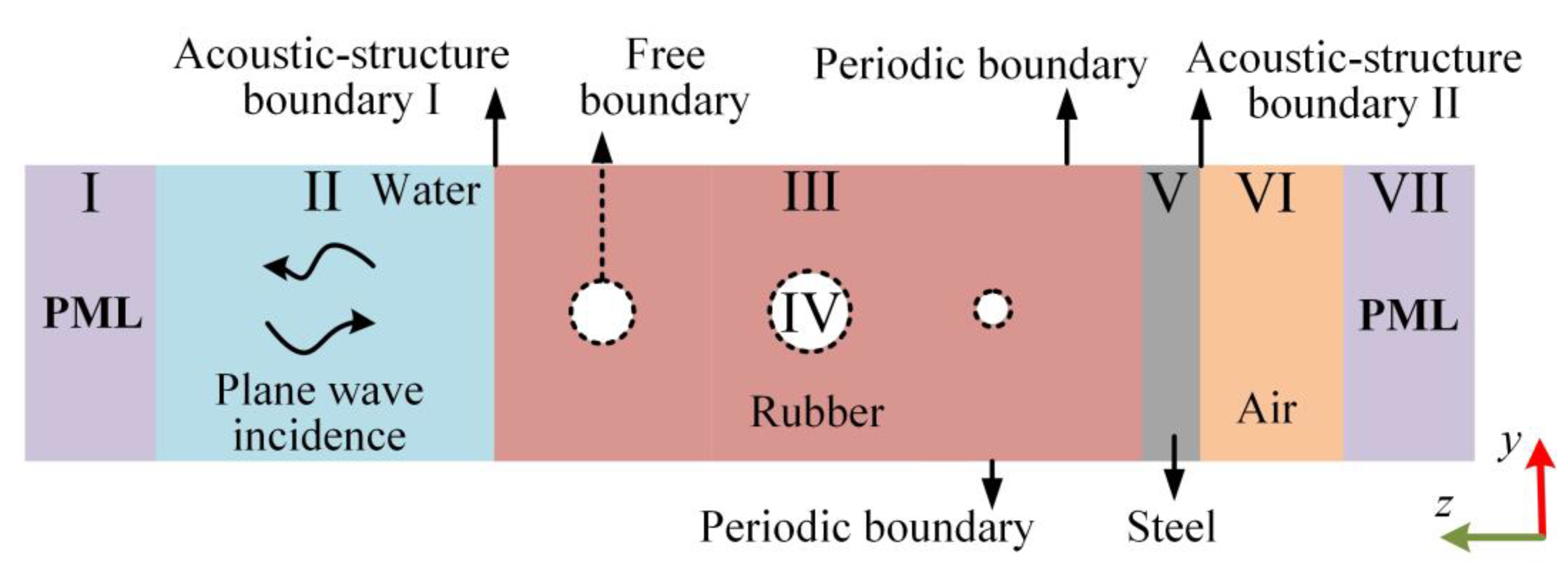
2.3. Modeling Settings for the Finite Element Simulation

Numerical simulation is performed in this paper with the finite-element analysis software COMSOL Multiphysics. After calculating the nonlinear geometric deformation via hydrostatic pressures, the deformable mesh under hydrostatic pressures will be directly imported into the acoustic-structure coupling module in simulation, avoiding discontinuous double modeling. Since the voids embedded into the tandem coating in Figure 1 are arranged periodically and extend infinitely in the x-direction, we could simplify such a model into a two-dimensional lattice to improve computational efficiency. The boundary condition and material settings in each region are shown in Figure 4. The acoustic pressure domain is labeled at Region II, IV, and VI. III, V marks the solid part, and I, VII refer to the perfect matching layer (PML) to mimic the nonreflecting boundary. The viscoelastic module is applied to the rubber domain. Floquet periods are applied to the upper and lower rubber boundaries, and the free boundary condition is set around the embedded voids. The acoustic-structure coupling border is paved between the solid domain and the water (air). Hydrostatic pressures are quantified as the boundary load inflicted on the acoustic-structure boundary I, while the displacement in the y-direction of the periodic border, i.e., the radial removal of the coating, should be specified as u y = 0 . In addition, the displacement in both y- and z-directions should also be restricted as u y = 0 ,   u z = 0 on acoustic-structure boundary II, which mimics the braced surface of the hull under hydrostatic pressures. The background pressure provides plane wave excitation existing in Region II. To solve the absorption coefficient numerically, we define the average operators in acoustic-structure boundaries I and II, from which the mean values for background and scattering pressure around the coating surfaces could be extracted.

3. Results

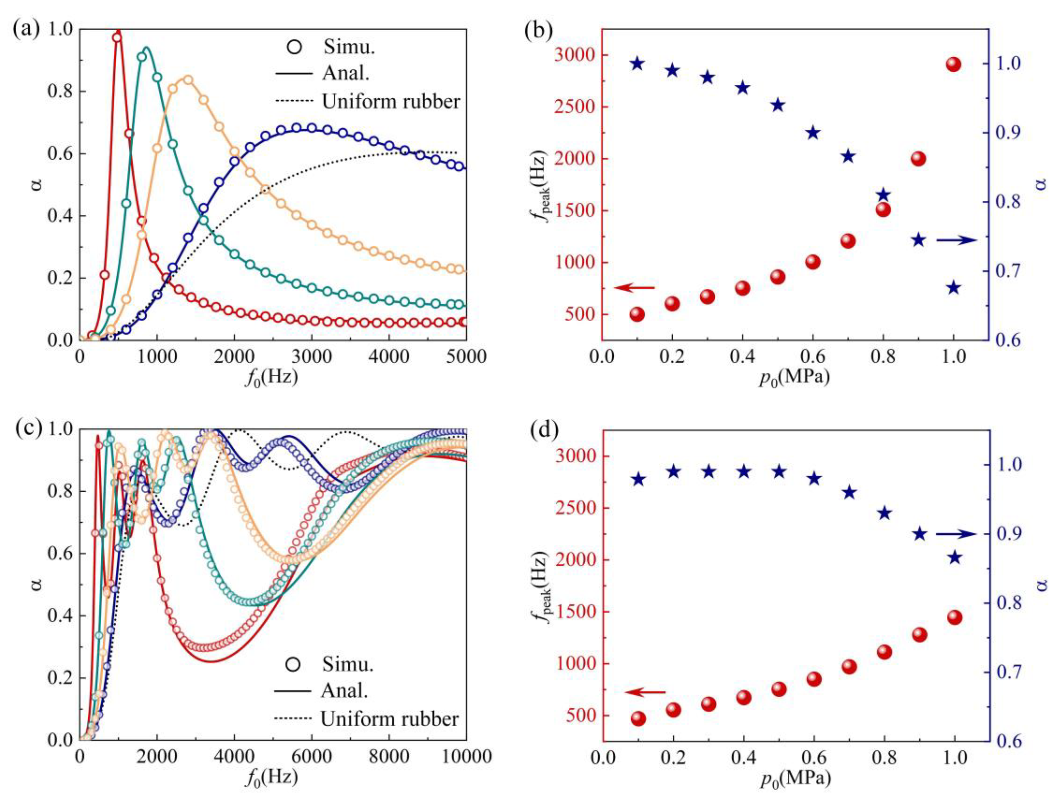
3.1. Effect of the Geometric Deformation on Absorption Performance under Hydrostatic Pressures

To elaborate on the absorption performance affected by hydrostatic pressures, we first analyzed deformation in the host medium embedded with resonant voids. Here, the single-layer void-resonant coating and multilayer coating are taken as examples to explore the geometric deformation. Following the aforementioned EMA model implanted with GA, the optimized parameters are listed in Table 2 and Table 3, for which quasi-perfect absorption α 0.8 bandwidths distribute among the single absorption peak 440~590 Hz and the triple peaks 420~540 Hz, 960~1100 Hz, and 1470~1760 Hz, respectively. The analysis procedure, including the solution of equivalent diameter of deformed voids, is exposited in Section 2.2, while the modeling details regarding finite element simulation are shown in Section 2.3.
The absorption performance of the single-layer void-resonant coating is stated in Figure 5a. The analytical and numerical data are represented by the solid lines and circles, while the crimson, olive, orange, and blue data refer to the ordinary pressure, 0.5 MPa, 0.75 MPa, and 1 MPa, respectively. The black dotted line shows the absorption performance from the homogeneous rubber without voids. Due to the monopole resonance of the single-layer void array [2,23,31,32], the hump absorption will occur at 500 Hz under ordinary pressure (0.1 MPa). Affected absorption performance is shown in detail in Figure 5b; here, the red globes correspond to the located frequency of the first absorption crest value, while the navy blue pentagrams refer to the absorption amplitude. As hydrostatic pressure increases, it is obvious that the formant shifts to higher frequencies and the absorption peak declines. When neglecting the change of mechanical parameters under hydrostatic pressures, the analytical absorption coefficients are in good agreement with the numerical data. By analogy with the analysis for single-layer coating, the analytical and numerical absorption coefficients from the tandem coating are illustrated in Figure 5c. Benefiting from the increment of resonant modes and the coupling effect between multilayer voids [21,33,34], quasi-perfect absorption from 420 Hz to 1720 Hz could be approached via this compact broadband absorber under ordinary pressures. The three resonance peaks would skew toward the higher frequencies, accompanied by the reduced amplitude and broader bandwidth, as shown in Figure 5c,d, which enhances the absorption efficiency in the middle-frequency band (2.5~5 kHz) at 1 MPa.
To clarify the affected mechanism via hydrostatic pressure, the stress distribution within the unit cell was performed in FE simulation as follows. Figure 6a,b represent the stress distribution of the single-layer coating at 0.5 MPa and 1 MPa. The black frame identifies the original outline under ordinary pressure. With the increase in hydrostatic pressure, the cross-section of the embedded void is squeezed into an irregular ellipse while the stress around the cavity increases significantly. The overall coating thickness decreases mildly at 1 MPa, which attributes to the reduction in the wave transmission path. Such compressed configuration would result in the altering of the resonance frequency and being close to the homogeneous medium, as represented by the black dotted line in Figure 5a. For the tandem anechoic coating, the deformed geometries consisting of multilayer voids are displayed in Figure 6c,d. The hydrostatic load perturbs the coupling effects between multilayer voids and changing the hump resonance at low frequencies. Therefore, the surface impedance originally adapted to the low-frequency incidence would fail and approach the performance of the uniform rubber without embedded voids. This provides an efficient approach to predict geometric deformation and the corresponding affected absorption performance via different hydrostatic pressures.

3.2. Effect of the Mechanical Parameters on Absorption Performance under Hydrostatic Load

Following the previous research [7,35], the viscoelastic medium’s shear modulus μ determines the underwater absorption performance in low frequencies and broadband. Nevertheless, μ would be enlarged and significantly affected by external hydrostatic load, while the corresponding loss factor μ decreases slightly [36]. Such envelope is consistent with the knowledge that the viscoelastic medium would be “hardened” under hydrostatic pressures. Herein, to precisely predict the absorption performance of the anechoic coating in the engineering environment, it is necessary to analyze the influence of the dynamic mechanical parameters of rubber on the absorption coefficient. Note that the first Lame constant λ of rubber is not sensitive to the hydrostatic pressures [36], so the modification of longitudinal modulus κ = λ + 2 μ under hydrostatic load was ignored in this work due to λ μ in elastically soft medium [23]. Figure 7 illustrates the complex plane diagram [37] for the absorption spectrum from the tandem coating in Table 3, where τ 1 and τ 2 refer to the scaling factors of the real and imaginary parts μ , μ of the shear modulus, respectively. A light-colored region means the tandem coating achieves quasi-perfect absorption at the specific frequency band when possessing the corresponding shear modulus. The absorption efficiency in low frequencies will be limited as the real part of shear modulus τ 1 μ increases, while the hump absorption is inclined to higher frequencies and the quasi-perfect absorption bandwidth is widened. In addition, each resonance hump’s bandwidth at low frequencies becomes constrictive when the shear loss factor τ 2 μ 0 . In other words, the variation of mechanical parameters via external hydrostatic load would also contribute to the disabled coating immediately, whose surface impedance had been precisely engineered to match the target frequencies under ordinary pressure. Above all, from the perspective of engineering applications, if the anechoic coating is just required to maintain impedance matching with the specific frequency band at the ordinary pressure, the anticipative absorption performance would not be approached under deeply submerged distances.

3.3. Experimental Validation

In this section, we conduct the experiment in an impedance tube filled with water to demonstrate the absorption dependence around hydrostatic pressures. Note that the tandem coating adopted in the investigation here was constructed with different void periods in each layer (Table 4) to improve the coupling effect between themselves [21]. Because a viscoelastic medium with arbitrary mechanical parameters is difficult to prepare in engineering, and for the sake of the manufacturing reliability for raw material, polyurethane (PU) was chosen for the host medium of a specimen. The longitudinal modulus and shear modulus of PU were measured by the dynamic thermomechanical analysis (TA Instrument Co., Ltd., New Castle, DE, USA, DMA 850), as κ = 1 + 0.3 i   G P a , μ = 0.4 + 0.36 i   M P a , and the static density ρ r = 1000   k g / m 3 . The properties of the elastic medium are assumed to be independent of the frequency. An experimental setup for underwater absorption measurement under hydrostatic pressures is shown in Figure 8a, which is composed of a hydroacoustic tube, pressurization system, sealing device, signal generation, and measurement system. The inner diameter of the pipe is 120 mm, corresponding to the reasonable measuring frequency band 500 Hz~10 kHz. As for the nitrogen pressurizing device, an accumulator chamber could precisely control the hydrostatic pressure loaded on the sample surface. The sealing device on the top part of the acoustic tube includes the sealing ring, vessel head structure, and fixture blocks. The acoustic specimen is assembled from PU embedded with multilayer voids and steel backing (Figure 8b,c), fed with sound waves generated by a transducer controlled by the power amplifier. Pressure signals are collected by the hydrophones , amplified, and sent to the data-acquisition hardware. Then, we can obtain the complex reflection coefficient and the absorption efficiency from the specimen surface.
Note that a three-dimensional numerical model imitating the experiment setup was built since the specimen is not an infinite extended periodic sample. The diameter is 118 mm; sample configuration and boundary condition are presented in Figure 8b,c. Different from the simulation settings in the Section 2.3, a rubber loop, i.e., a waterproof coating, must be wrapped around the sample to prevent water embedment through the internal voids. Dynamic mechanical parameters of viscoelastic materials, including the complex longitudinal and shear modulus under hydrostatic pressures, refer to the evolution law given in reference [36] and are then substituted into the analytical method and numerical simulation. Figure 9 illustrates the absorption coefficients compared to the measured results and indicates good agreement with each other. Black dotted lines, red circles, and olive pentagrams represent the analytical, numerical, and measured results. Figure 9a refers to the comparison under ordinary pressure. The quasi-perfect absorption α > 0.7 in a wide and low-frequency band (600~4000 Hz, the faint yellow region marked in Figure 9a) was realized with the tandem coating, whose thickness is λ / 16.7 at 600 Hz. Figure 9b–d show the absorption spectrum under hydrostatic pressures of 0.5 MPa, 1 MPa, and 2 MPa, successively. Affected by compression deformation and mechanical parameter changes, the humps absorption at low frequencies significantly decreases and moves to a higher band. Meanwhile, the absorption efficiency above 4 kHz was improved observably, consistent with Figure 5c and Figure 7a. The analytical and numerical spectra coincide with the measured data at each pressure, proving the EMA theory’s accuracy and the FE simulation within 2 MPa. However, there is slight skewing in the low-frequency band because the derivation of the EMA method was restricted to the boundary condition that the coating extends periodically and indefinitely, which is different from the specimen in simulation and experiment.

4. Discussion

This work contributes to predicting the low-frequency and broadband absorption performance via tandem coupled coatings within 2 MPa (the submerged depth of 200 m). Nevertheless, the mechanical parameters of the host medium were assumed to be constant among the working frequencies for simplicity. The spectrum of mechanical parameters under hydrostatic pressures needs quantification in the subsequent research. On the other hand, based on the absorption degeneration investigated in this paper, it is feasible to design the quasi-perfect absorption coatings working at sub-kilohertz under hydrostatic pressures. This can be expected, as GA optimization is invoking the numerical deformed model to calculate the absorption performance repeatedly with the determined mechanical parameters, then judging the individual fitness until the global optimal configuration is obtained under specific pressures. This is crucial for low-frequency noise reduction and improvement of the comprehensive stealth performance of underwater vehicles at considerable diving depth.

5. Conclusions

In summary, we theoretically, numerically, and experimentally investigated the anechoic coatings embedded with perforative voids, illustrating the variation of absorption performance under hydrostatic pressures. To elucidate the physical mechanism inside this tandem resonant coating, the steady-state deformation was analyzed numerically. Then, the relation between deformed geometry, the dynamic mechanical parameters of the host medium, and the corresponding underwater absorption degeneration were characterized in this paper. In addition, we carried out the experimental verification in the underwater impedance tube, indicating that the hump resonance at low frequencies would incline to a higher band. The absorption performance in middle and high bands were improved due to the widening of the absorption bandwidth under hydrostatic pressures.
For all this, our design paves the way for underwater acoustic impedance engineering via artificial functional devices in low frequency and broadband, and suggests an accurate prediction for extreme wave manipulation at different diving depths.

Author Contributions

Conceptualization, X.F. and W.W. (Wenwei Wu); data curation, X.Z.; investigation, X.P.; methodology, X.F., X.P., D.L., X.Y. and Y.J.; software, X.F.; supervision, D.L., Y.J., W.W. (Weibo Wang) and W.W. (Wenwei Wu); validation, X.F. and W.W. (Weibo Wang); writing—original draft, X.F., Y.J. and W.W. (Weibo Wang); writing—review and editing, X.F., X.P., D.L., X.Y., Y.J., W.W. (Weibo Wang) and W.W. (Wenwei Wu). All authors have read and agreed to the published version of the manuscript.

Funding

This work is supported by the National Natural Science Foundation of China (No. U2241243, 12272267), the Jiangsu Science and Technology Agency (Grants No. BK20230182), the Shanghai Science and Technology Committee (Grant No. 22JC1404100, 21JC1405600), the Jiangsu Funding Program for Excellent Postdoctoral Talent (No. 2023ZB572), and the Young Elite Scientists Sponsorship Program by CAST (Grant No. 2021QNRC001).

Institutional Review Board Statement

Not applicable.

Informed Consent Statement

Not applicable.

Data Availability Statement

Data will be made available on request.

Conflicts of Interest

The authors declare that they have no known competing financial interests or personal relationships that could have appeared to influence the work reported in this paper.

References

  1. Gaunaurd, G. One-dimensional model for acoustic absorption in a viscoelastic medium containing short cylindrical cavities. J. Acoust. Soc. Am. 1977, 62, 298–307. [Google Scholar] [CrossRef]
  2. Lane, R. Absorption mechanisms for waterborne sound in Alberich anechoic layers. Ultrasonics 1981, 19, 28–30. [Google Scholar] [CrossRef]
  3. Bai, H.; Zhan, Z.; Liu, J.; Ren, Z. From local structure to overall performance: An overview on the design of an acoustic coating. Materials 2019, 12, 2509. [Google Scholar] [CrossRef] [PubMed]
  4. Fu, Y.; Kabir, I.I.; Yeoh, G.H.; Peng, Z. A review on polymer-based materials for underwater sound absorption. Polym. Test. 2021, 96, 107115. [Google Scholar] [CrossRef]
  5. Ivansson, S.M. Numerical design of Alberich anechoic coatings with superellipsoidal cavities of mixed sizes. J. Acoust. Soc. Am. 2008, 124, 1974–1984. [Google Scholar] [CrossRef]
  6. Meyer, E.; Brendel, K.; Tamm, K. Pulsation oscillations of cavities in rubber. J. Acoust. Soc. Am. 1958, 30, 1116–1124. [Google Scholar] [CrossRef]
  7. Yang, H.; Zhao, H.; Wen, J. Theory and numerical method for the effects of hydrostatic pressure on sound absorption of underwater acoustic coatings with air cavities. J. Sound Vib. 2022, 533, 116985. [Google Scholar] [CrossRef]
  8. Li, H.; Zhu, X.; Yang, G. Discussion on System of Polyurethane Underwater Anechoic Material and Research Progress in Polyurethane Anechoic Structure. Polyurethane Ind. 2009, 5. [Google Scholar] [CrossRef]
  9. Sharma, G.S.; Skvortsov, A.; MacGillivray, I.; Kessissoglou, N. Sound transmission through a periodically voided soft elastic medium submerged in water. Wave Motion 2017, 70, 101–112. [Google Scholar] [CrossRef]
  10. Sharma, G.S.; Faverjon, B.; Dureisseix, D.; Skvortsov, A.; Kessissoglou, N. Acoustic Performance of a Periodically Voided Viscoelastic Medium With Uncertainty in Design Parameters. J. Vib. Acoust. 2020, 142, 061002. [Google Scholar] [CrossRef]
  11. Gu, Y.; Zhong, H.; Bao, B.; Wang, Q.; Wu, J. Experimental investigation of underwater locally multi-resonant metamaterials under high hydrostatic pressure for low frequency sound absorption. Appl. Acoust. 2021, 172, 107605. [Google Scholar] [CrossRef]
  12. Fu, Y.; Wang, H.; Cao, P. Numerical design and optimization of metamaterials for underwater sound absorption at various hydrostatic pressures. J. Low Freq. Noise Vib. Act. Control 2023, 42, 1434–1450. [Google Scholar] [CrossRef]
  13. Zhong, H.; Tian, Y.; Gao, N.; Lu, K.; Wu, J. Ultra-thin composite underwater honeycomb-type acoustic metamaterial with broadband sound insulation and high hydrostatic pressure resistance. Compos. Struct. 2021, 277, 114603. [Google Scholar] [CrossRef]
  14. Gu, Y.; Long, H.; Cheng, Y.; Deng, M.; Liu, X. Ultrathin composite metasurface for absorbing subkilohertz low-frequency underwater sound. Phys. Rev. Appl. 2021, 16, 014021. [Google Scholar] [CrossRef]
  15. Feng, J.; Liang, Q.; Dou, Y.; He, J.; He, J.; Chen, T. Ultrathin Underwater Sound-Absorbing Metasurface by Coupling Local Resonance with Cavity Resonance. Phys. Rev. Appl. 2022, 18, 034054. [Google Scholar] [CrossRef]
  16. Zou, M.; Wu, W.; Yu, X.; Liao, B. Calculation of acoustic coating’s Impedance under hydrostatic pressure. Ship Sci. Technol. 2013, 35, 57–60. [Google Scholar]
  17. Tao, M.; Zhuo, L. Effect of Hydrostatic Pressure on Acoustic Performance of Sound Absorption Coating. J. Shanghai Jiaotong Univ. 2011, 45, 6. [Google Scholar]
  18. Dong, W.; Chen, M. Sound absorption performance analysis of anechoic coating under hydrostatic pressure considering cavity pressure. Chin. J. Ship Res. 2022, 17, 9. [Google Scholar]
  19. Zhao, H.; Wen, J.; Yang, H.; Lv, L.; Wen, X. Backing effects on the underwater acoustic absorption of a viscoelastic slab with locally resonant scatterers. Appl. Acoust. 2014, 76, 48–51. [Google Scholar] [CrossRef]
  20. Wen, J.; Zhao, H.; Lv, L.; Yuan, B.; Wang, G.; Wen, X. Effects of locally resonant modes on underwater sound absorption in viscoelastic materials. J. Acoust. Soc. Am. 2011, 130, 1201–1208. [Google Scholar] [CrossRef]
  21. Fang, X.; Yin, X.; Wu, J.; Li, Y.; Li, H.; Wang, W.; Li, Y.; Wu, W. Underwater metagratings for sub-kilohertz low frequency and broadband sound absorption. Int. J. Mech. Sci. 2023, 260, 108630. [Google Scholar] [CrossRef]
  22. Leroy, V.; Bretagne, A.; Fink, M.; Willaime, H.; Tabeling, P.; Tourin, A. Design and characterization of bubble phononic crystals. Appl. Phys. Lett. 2009, 95, 171904. [Google Scholar] [CrossRef]
  23. Sharma, G.S.; Skvortsov, A.; MacGillivray, I.; Kessissoglou, N. Acoustic performance of gratings of cylindrical voids in a soft elastic medium with a steel backing. J. Acoust. Soc. Am. 2017, 141, 4694–4704. [Google Scholar] [CrossRef]
  24. Morse, P.M.; Ingard, K.U. Theoretical Acoustics; Princeton University Press: Princeton, NJ, USA, 1986. [Google Scholar]
  25. Rybak, S.A.; Zozulya, O.M. One-dimensional modulation instability of wave packets in media with resonant dispersion. Phys. A 1997, 241, 128–132. [Google Scholar] [CrossRef]
  26. Wu, Y. Effective medium theory for elastic metamaterials in two dimensions. Phys. Rev. B 2007, 76, 205313. [Google Scholar] [CrossRef]
  27. Leroy, V.; Strybulevych, A.; Scanlon, M.; Page, J. Transmission of ultrasound through a single layer of bubbles. Eur. Phys. J. E 2009, 29, 123–130. [Google Scholar] [CrossRef] [PubMed]
  28. Ingard, U. On the Theory and Design of Acoustic Resonators. J. Acoust. Soc. Am. 2005, 25, 1037–1061. [Google Scholar] [CrossRef]
  29. Stinson, M.R. The propagation of plane sound waves in narrow and wide circular tubes, and generalization to uniform tubes of arbitrary cross-sectional shape. J. Acoust. Soc. Am. 1991, 89, 550–558. [Google Scholar] [CrossRef]
  30. Li, D.T.; Huang, S.B.; Cheng, Y.; Li, Y. Compact asymmetric sound absorber at the exceptional point. Sci. China Phys. Mech. 2021, 64, 24430. [Google Scholar] [CrossRef]
  31. Liu, B.; Huang, S.; Zheng, B.; Chen, X.; Zhao, J.; Qi, X.; Li, Y.; Liu, S. Tunable composite lattice structure for low-frequency and ultra-broadband underwater sound absorption. J. Acoust. Soc. Am. 2023, 153, 415–422. [Google Scholar] [CrossRef] [PubMed]
  32. Tjutekin, V.V. Scattering of plane waves by a cylindrical cavity in an isotropic elastic medium. Sov. Phys.-Acoust. 1959, 17, 125. [Google Scholar]
  33. Zhou, Z.; Huang, S.; Li, D.; Zhu, J.; Li, Y. Broadband impedance modulation via non-local acoustic metamaterials. Natl. Sci. Rev. 2022, 9, nwab171. [Google Scholar] [CrossRef]
  34. Huang, S.; Zhou, Z.; Li, D.; Liu, T.; Wang, X.; Zhu, J.; Li, Y. Compact broadband acoustic sink with coherently coupled weak resonances. Sci. Bull. 2020, 65, 373–379. [Google Scholar] [CrossRef]
  35. Beili, Z.; Keming, R. Acoustic Properties Analysis of Elastomer with Cylindrical Bores Using Equivalent Parametric Method. J. Shanghai Jiaotong Univ. 1997, 31, 20–25. [Google Scholar]
  36. Huang, X.; Zhu, B.; Hu, P.; Hua, H. Measurement of Dynamic Properties of Rubber under Hydrostatic Pressure by Water-filled Acoustic Tube. J. Shanghai Jiaotong Univ. 2013, 47, 1503–1508+1519. [Google Scholar]
  37. Romero-García, V.; Theocharis, G.; Richoux, O.; Pagneux, V. Use of complex frequency plane to design broadband and sub-wavelength absorbers. J. Acoust. Soc. Am. 2016, 139, 3395. [Google Scholar] [CrossRef] [PubMed]
Figure 1. Schematic of the proposed tandem coupling coating. (a) The multilayer coating consists of rubber embedded with periodic voids and steel backing. The incident waves along the -z-direction are perpendicular to the coating surface. (b) Cross-section of the multilayer coating. p i and p r represent the complex incident and reflection pressure, respectively. a, d, and t are the voids’ period, diameter, and thickness of one layer. (c) An equivalent model including effective homogeneous layers (EHLs). t e refers to the approximate height of EHL.
Jmse 12 00543 g001
Figure 2. The flowchart of the genetic algorithm (GA).
Jmse 12 00543 g002
Figure 3. The flow chart for absorption performance estimation of the anechoic coatings considering hydrostatic pressure.
Jmse 12 00543 g003
Figure 4. Simulation settings for the tandem coupling coating in COMSOL Multiphysics.
Jmse 12 00543 g004
Figure 5. The absorption spectra of the single-layer (a) and tandem (c) anechoic coatings under compression. The analytical and numerical solutions are represented by the colored curves and circles, respectively. The crimson, olive, orange, and blue data correspond to the ordinary pressure, 0.5 MPa, 0.75 MPa, and 1 MPa, respectively. The black dotted line represents the spectra of the uniform rubber. Panels (b,d) show the variation trend of the 1st absorption peak from the single-layer and tandem coatings, in which the red globe and navy blue pentagram refer to the located frequency and amplitude of the 1st absorption peak.
Jmse 12 00543 g005
Figure 6. The schematic diagram of the unit cell deformation and stress distribution under hydrostatic load. (a) Single-layer coating at 0.5 MPa; (b) single-layer coating at 1 MPa; (c) tandem coating at 0.5 MPa; (d) tandem coating at 1 MPa. The original outline of unit cell under ordinary pressure is depicted by the black frame. And red arrows indicate the pressure direction.
Jmse 12 00543 g006
Figure 7. The evolution of absorption spectra of tandem coupled coating via shear modulus μ . The color bar represents the absorption coefficients α , and the light regions refer to quasi-perfect absorption. The change of α with real part scaling factor τ 1 and imaginary part τ 2 of shear modulus are shown in (a,b), respectively.
Jmse 12 00543 g007
Figure 8. (a) Experimental setup for sound absorption measurement under different hydrostatic pressures. (b) Sample image and the installation diagram. (c) Three-dimensional FE simulation settings, cross-section drawn, and the internal configuration of the tandem coating.
Jmse 12 00543 g008
Figure 9. Comparison of sound absorption coefficients of the coating sample under ordinary pressure (a), 0.5 MPa (b), 1 MPa (c), and 2 MPa (d). Black dotted curves, red circles, and olive pentagrams refer to the data from the analytical solutions, simulation, and experimental results. The faint yellow region in (a) refers to the quasi-perfect absorption in low frequencies at ordinary pressure.
Jmse 12 00543 g009
Table 1. Mechanical parameters of solid materials.
Density   ρ k g / m 3 Young s   Modulus   E M P a Poisson s   Ratio   σ Loss   Factor   η
Rubber10001.80.4990.3
Steel7890 2.1 × 10 5 0.30
Table 2. Geometric parameters of the single-layer coating.
Void   Diameter   d n m m Coating   Thickness   t n m m Void   Period   a m m Steel   Thickness   t s t m m
3.421.321.817.3
Table 3. Geometric parameters of the tandem coating.
Layer Sequence Void   Diameter   d n m m Layer   Thickness   t n m m Void   Period   a m m Steel   Thickness   t s t m m
12.358.437.94
23.764.5
35.546.1
Table 4. Geometric parameters of the specimen.
Layer Sequence Void   Diameter   d n m m Layer   Thickness   t n m m Void   Period   a m m Steel   Thickness   t s t m m
11.526.024.44.8
23.287.880.1
34.232.430.1
Disclaimer/Publisher’s Note: The statements, opinions and data contained in all publications are solely those of the individual author(s) and contributor(s) and not of MDPI and/or the editor(s). MDPI and/or the editor(s) disclaim responsibility for any injury to people or property resulting from any ideas, methods, instructions or products referred to in the content.

