Article

An Equivalent Linear Method to Predict Nonlinear Bending Mechanics of Dredging Floating Hose String

1
State Key Laboratory of Ocean Engineering, School of Naval Architecture, Ocean and Civil Engineering, Shanghai Jiao Tong University, Shanghai 200240, China
2
School of Naval Architecture, Ocean and Civil Engineering, Shanghai Jiao Tong University, Shanghai 200240, China
3
CCCC Guangzhou Dredging Co., Ltd., Guangzhou 510220, China
*
Author to whom correspondence should be addressed.
J. Mar. Sci. Eng. 2024, 12(3), 421; https://doi.org/10.3390/jmse12030421
Submission received: 2 February 2024 / Revised: 20 February 2024 / Accepted: 24 February 2024 / Published: 27 February 2024
(This article belongs to the Special Issue Advances in Ships and Marine Structures)

Abstract

:
Dredging hoses are flexible and are particularly suitable for slurry transportations for mud or sand in dredging projects. To achieve sufficient bending stiffness and to prevent the pipe body from collapsing, this type of hose segment is a composite structure that is embedded with several cord reinforcement layers and steel wires in its rubber layer. To quickly evaluate the nonlinear bending mechanical properties of rubber hoses, this study proposes the equivalent stiffness method of linear superposition, which is verified by test data and numerical results. The results show that the equivalent bending stiffness method proposed in this study is in good agreement with numerical and experimental results. Then, by comparing the calculation results of the hose string, it was demonstrated that the linear stiffness superposition method proposed in this study can also accurately predict the bending mechanical behavior characteristics of string hose, and provide reliable guidance for hose design in practice.

1. Introduction

A dredging floating hose is a specialized type of hose that connects the dredge vessel to the dredge head, facilitating the transport of materials such as silt, sand, coral, and small stones from the dredging site to the designated location, as shown in Figure 1. These hoses are typically made from a combination of rubber matrix and other reinforced materials, such as steel wires and cords, to ensure durability and flexibility. Attributed to the huge demand in the dredging market, the global floating dredging hose market is expected to grow at an annual growth rate of nearly 3.3% during the forecast period [1]. Currently, many companies have the ability to produce various types of dredging hoses, for example, Goodyear’s SEAWING series of hoses, Dunlop’s double-layered reinforced structure hoses, Kleber’s large-diameter series of hoses, and Uniroyal Manuli’s sealing series hoses. Based on almost 60 years of production and application experience, a number of specifications have been developed for the design, testing, and application of dredging hoses, such as JIS F 3995:2000 [2], GMPHOM [3], API 17K [4], ISO 28017:2018 [5], etc. These standards and guides are quite beneficial for design specifications and structural details in product development; however, it is important to note that a gap still exists between academic research and industrial application. Because of the expertise required for hoses, there are very few research facilities and institutes that work on them [6].
The engineering application characteristics of dredging floating hoses require a high level of system safety due to their multi-layer composite structure and special mechanical properties. Considering the working conditions of floating hoses at sea, they are subjected to various forces such as gravity, buoyancy, wave loads, and ocean currents. As a result, hoses may experience twisting, bending, and stretching, which can lead to misalignment, cracking, loose joints, and even breakage. The analysis and design of offshore floating hose systems are extremely challenging due to the combined stress caused by the movement of ships and buoys, and the inherent stress of the piping system. Additionally, the deformation and load solution of hoses also involves nonlinear analysis, including geometric nonlinearity, material nonlinearity, and contact nonlinearity. Geometric nonlinearity refers to the large deformation of hoses due to sufficient flexibility. Material nonlinearity refers to the hyperelastic mechanical behavior of the main component of a hose, rubber, and the internal embedded cords with different orientation angles. Contact nonlinearity refers to the incomplete adhesion between layers and steel wires, as well as the asymmetry of the hose structure. In this study, material nonlinearity was emphasized. Therefore, during the preliminary design stage of hoses, it is crucial to establish an overall mathematical model of the floating hose group to obtain inherent mechanical characteristics. This will lay a foundation for further dynamic analysis.
Many scholars have conducted research on the principles and applications of marine hoses. Tonato et al. [7] studied the nonlinear mechanical behavior of aramid/polyamide hybrid reinforced cord hoses using both macroscopic and microscopic analysis methods. Zhou et al. [8] established a unified mathematical method based on the anisotropic laminated composite theory to provide analytical results for flexible hoses with any multi-layer reinforcement layer under internal pressure, and further conducted failure analysis. Amaechi et al. [6] comprehensively reviewed the technologies on bonded hoses for marine applications in the offshore industry. Gao et al. [9] proposed a simplified theoretical method to predict the response of an offshore bonded composite hose to lateral crush load.
Many of the above studies on floating hoses have mainly focused on a single hose segment, with greater emphasis on the tensile mechanical properties. In fact, due to wave loads, floating hoses on the sea are in a bent state. Providing a method that can quickly predict the bending load of hoses is of great practical engineering significance. This study investigates the bending characteristics of a dredging floating hose from three perspectives: theoretical, numerical, and experimental. Firstly, this study proposes a theoretical solution method for hose bending based on beam theory. The bending of rubber hoses is decomposed into pure bending and compression processes. The relationship between these two processes can be determined by using the pure bending installation angle as a bridge. The problem can be transformed by solving the total stiffness matrix. Based on the hyperelastic model, spring principle, and laminated theory, constitutive models for the three main components of the hose, including the rubber matrix, steel wire, and composite reinforcement layer, have been established. Afterwards, a simplified finite element model of the structure is then constructed based on embedded element technology. By comparing theoretical solutions, finite element method (FEM) results, and bending test results, the feasibility and accuracy of the proposed theoretical solution method are verified. Finally, bending performances of hose string are predicted and compared with the finite element results. The research approach is illustrated in Figure 2.

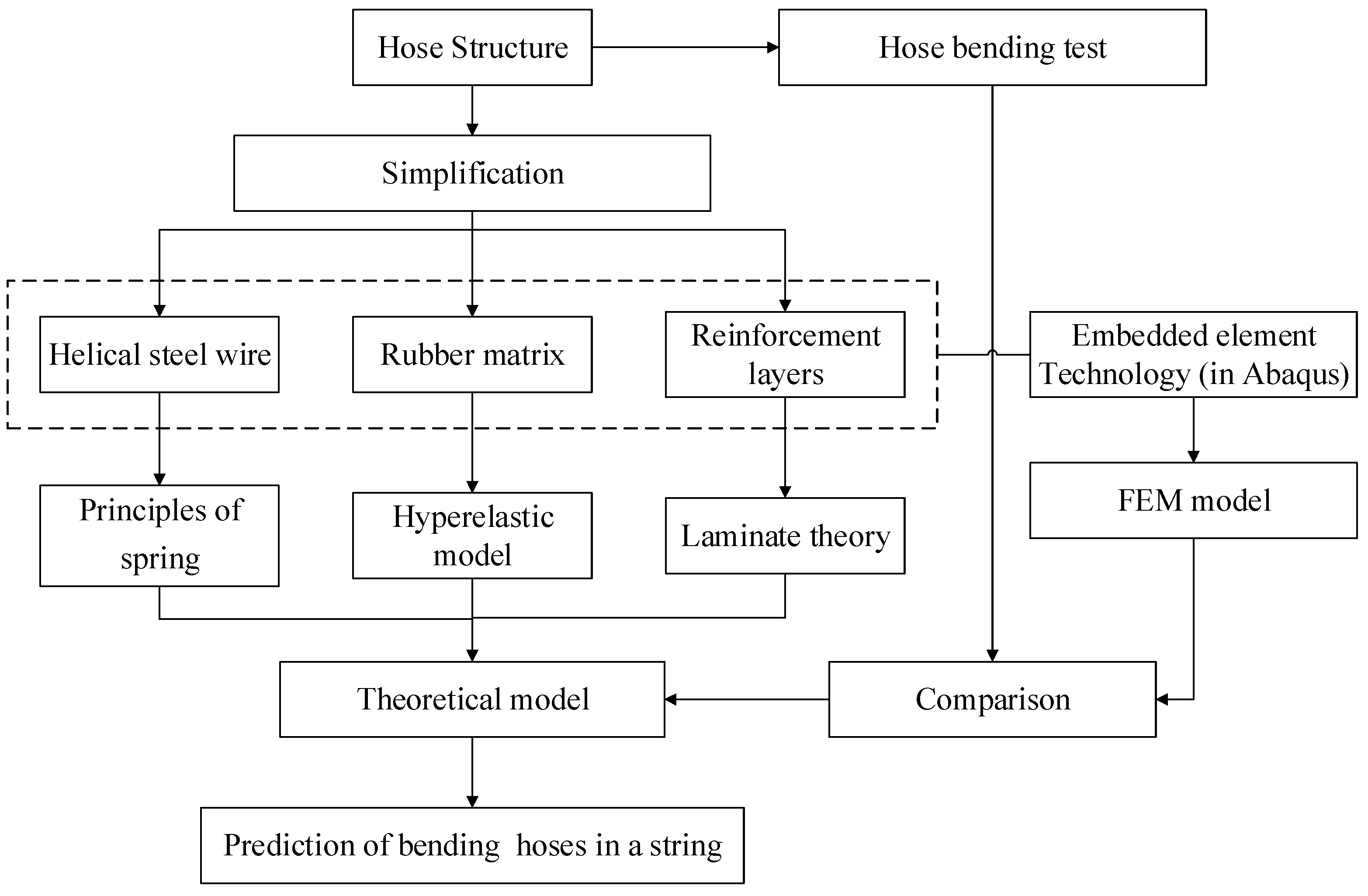
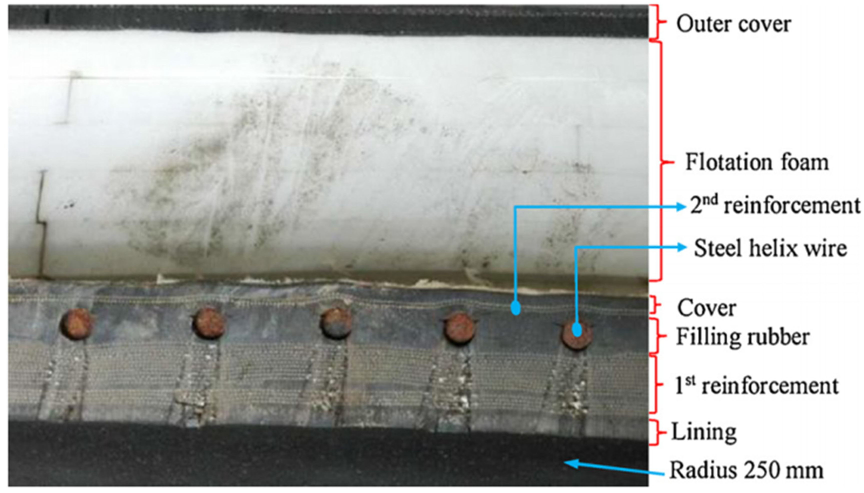
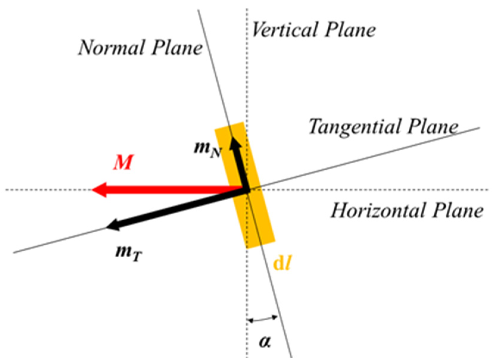
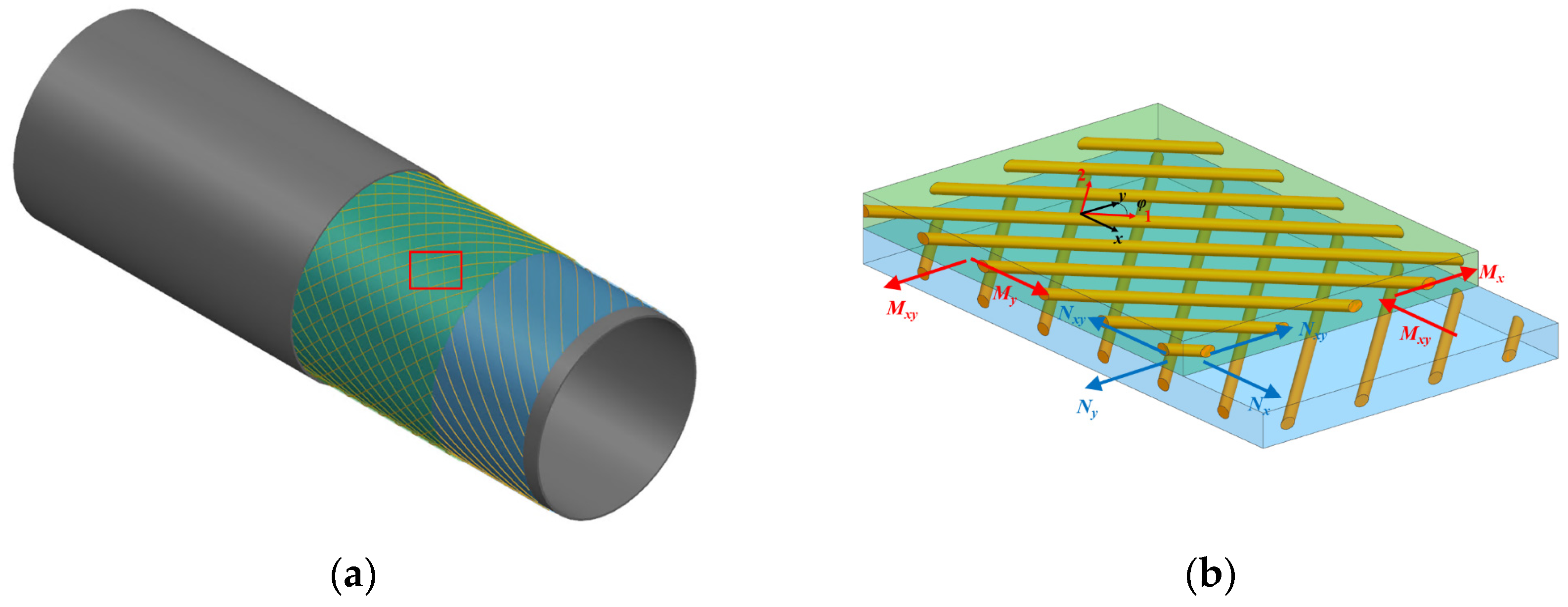
2. Hose Structure and Assumption

The dredging floating hose is an approximate cylinder duct filled with water composed of multiple layers (see Figure 3 and Figure 4). The middle floating foam is primarily composed of pure rubber with low density, which serves to provide buoyancy and to seal the high-pressure liquid transported in the pipeline made of synthetic tire cord fabric, serving as a reinforcing layer that maintains the pressure of the compressed air like an airbag. In addition to the composite reinforcement layer, the hose is also embedded with helical steel wires.
As can be seen in Figure 4, the processing technology of the floating hose used in engineering practice is the essential complex, so it is impossible to describe all the details in theoretical or finite element calculations, and the model has to be simplified. Therefore, the following assumptions are made:
(a)
The whole hose is divided into three main components based on the structure and material characteristics of the floating hose, including the rubber matrix, cord reinforcement layer, and helical steel wire. There are no material defects in any group of structures. The floating body and other outer structures do not bear loads when the hose bends.
(b)
The adhesion assumption, wherein each layer maintains adhesion without separation under external forces.
(c)
The cord layer is considered a linear elastic material within a small deformation range.

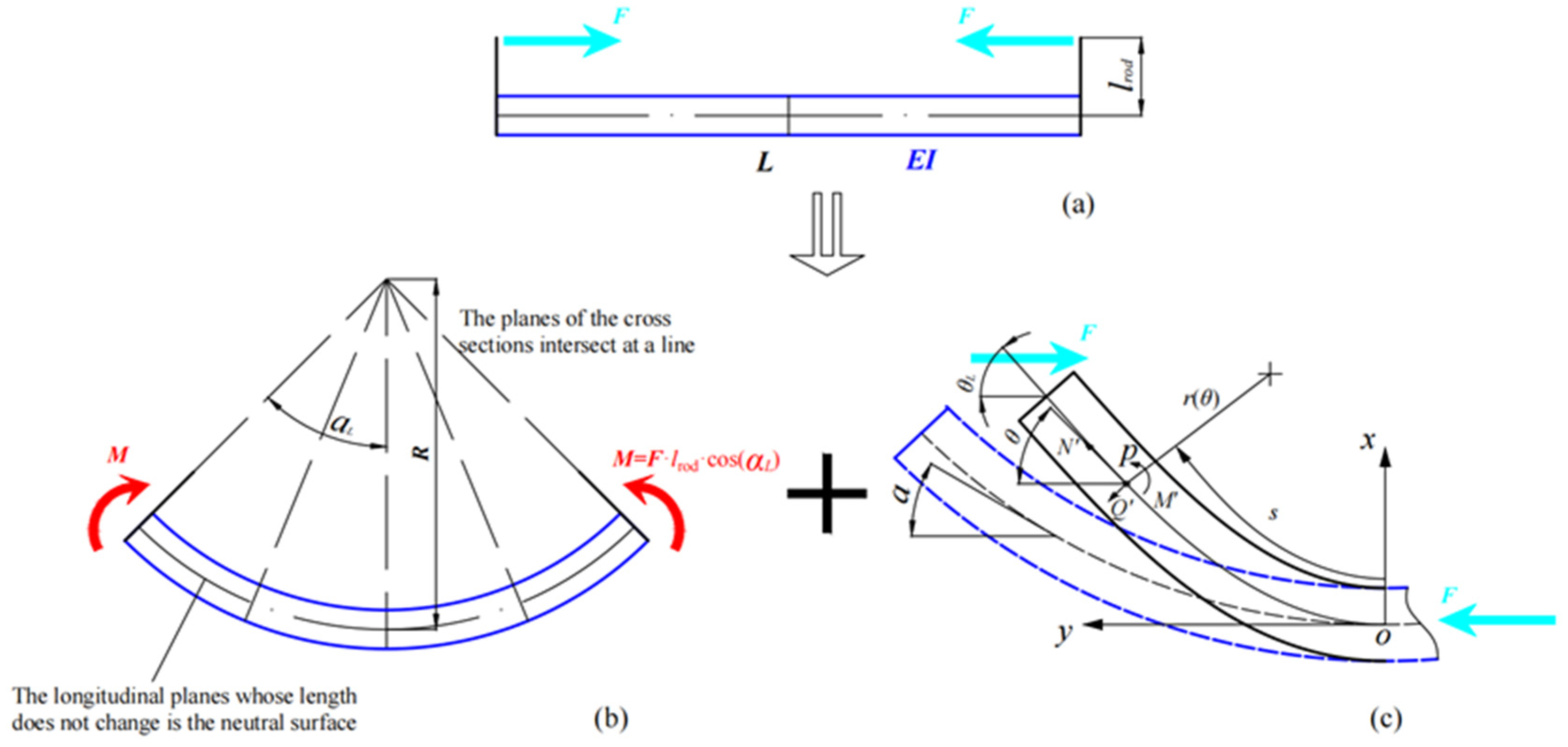
3. Theoretical Analysis Solution

Given that the length of the hose is much larger than the diameter, the bent hose operating in marine engineering can be seen as a free beam. Figure 5a illustrates the bending process of a beam connected with rigid bending rods driven by tension force F. Following the principle of force transmissibility, this process can be decomposed into two parts: (1) the pure bending process of a straight beam only under bending moments, and (2) the bending process of a curved beam under external forces.
(1) Straight beam pure bending
According to the basic beam theory, as shown in Figure 5b [11], the relationship between the curvature radius of a beam after bending and the bending moment at both ends can be expressed as
1 R = M E I = F l r o d cos α L E I
Based on the relevant assumptions in Section 2, the total bending stiffness of the rubber hose is divided into three parts: pure rubber, helical steel wire, and a reinforcement layer. Consider the geometric relationship after bending:
R 2 α L = L
F = 1 l r o d cos α L 2 α L L E I total = 1 l r o d cos α L 2 α L L E I rubber + E I wire + E I reinforcement
Therefore, the most important step for solving hose bending is determining the equivalent bending stiffness of different components by establishing material constitutive relations. Then, the total bending stiffness, (EI)total, can be obtained by linearly superimposing them.
(2) Curved beam bending
Figure 5c shows the establishment of a coordinate system xoy at the midpoint of the beam. The curve coordinates of any point p on the axis of the curved beam are expressed as s, and the section angles before and after deformation are expressed as α ∈ (0, αL) and θ ∈ (0, θL), respectively. Then, the rotation angle of the cross-section at point p can be expressed as
φ = θ α
According to the Euler–Bernoulli beam theory, the microelement of a curved beam at point p can be expressed as follows, ignoring the axial elongation:
d s = R α d α = r θ d θ
where R and r represent the curvature radius before and after deformation of the curved beam.
The equilibrium equation at point p is
Q = F sin θ = d M d s N = F cos θ M = E I d φ d s
The deformation control equation can be expressed as
d 2 θ d α 2 = d 2 φ d α 2 = F R 2 E I sin θ = η 2 sin θ
Equation (7) has a general solution:
1 2 d θ d α 2 = η 2 cos θ + D
where D is the integral constant.
For a curved beam that is simply supported, the bending moment at the end is always zero. Therefore, the following are the boundary conditions:
θ α L = θ L d θ d α α = α L = 1
Combining Equation (8) and boundary condition (9), Equations (10) and (11) can be obtained.
d θ d α = 1 + 2 η 2 cos θ cos θ L
0 θ L d θ 1 + 2 η 2 cos θ cos θ L = α L
Given a series of curved beam end installation angles αL, the corresponding external force term F (or η) can be determined through Formula (3). The shooting method can then be employed to solve integral Equation (11) and obtain the numerical solution for the large deformation of the free beam driven by bending rods.

3.1. The Constitutive of Rubber Matrix

For rubber-like material at finite strain, the hyperelastic model provides a general strain-energy potential to describe the material behavior for nearly incompressible elastomers [12].
W = f I 1 ,   I 2 ,   I 3
where W is the strain-energy density, and I1, I2, and I3 are the three invariants of each of the two Cauchy–Green deformation tensors.
Rivlin [13] specified the form of Equation (12) with the power series.
W = i + j + k = 1 C i j k I 1 3 i I 2 3 j I 3 1 k
where the numbers of 3 and 1 are included in the formulation to force W = 0 without deformation. For incompressible materials, I3 = 1.
The primary, and probably best known and most widely employed, strain-energy function formulation is the Mooney–Rivlin model [13,14], which reduces to the widely known neo-Hookean model. Other models that have been demonstrated to be quite appropriate and desirable for modeling rubber-like materials are the Yeoh [15], Ogden [16], Arruda–Boyce (statistically-based) [17], and Gent models [18].
Yeoh [15] proposed the following three-term strain-energy function, where only the first strain invariant I1 appears. It has the specific form of
W = C 10 I 1 3 + C 20 I 1 3 2 + C 30 I 1 3 3
Given the nonlinearity of the material and the degree of agreement with the test results, the authors of this study ultimately applied the Yeoh model to describe the hyperelastic mechanical property of the rubber in the hose.
The equivalent bending stiffness of rubber pipes can be expressed as
E I rubber = E λ I rubber = σ λ ε I rubber = σ λ λ λ ε I rubber   = λ 2 λ λ 2 W I 1 + λ 1 W I 2 I rubber     = λ 2 λ λ 2 W I 1 π 64 D rubber 4 d rubber 4
where λ is the elongation rate for uniaxial stretching, λ = 1 + ε and I1 = λ2 + 2λ−1; Irubber is the equivalent moment of inertia of the rubber pipe’s cross-sectional area; Drubber is the outer diameter of rubber pipe; and drubber is the inner diameter of rubber pipe.

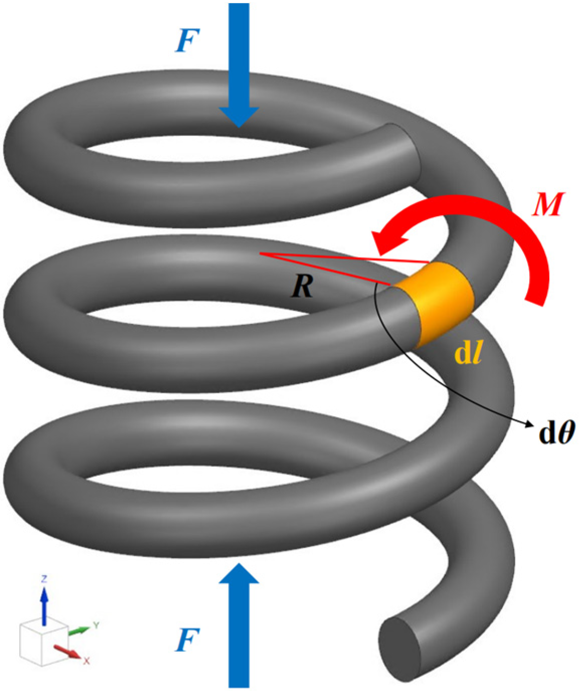
3.2. The Constitutive of Helical Steel Wire

As the radius of the cross-section of helical steel wire is much smaller than the radius of coil, the helical steel wire can be equivalent to a helical spring, and the elastic coefficient can be determined using the energy method [19]. Figure 6 shows a schematic diagram of the force acting on the spring during compression.
The couple M acting in the vertical plane is shown as a vector. The couple is equal to the product of the axial force F with the arm R to the force of a couple:
M = F R = F D 2
where D is the mean coil diameter of the spring.
As shown in Figure 7, the couple M resolves into two components lied in planes, which are tangential and normal to the helix, respectively.
m N = M sin α m T = M cos α
where α designates the inclination of the helix with any plane perpendicular to the axis of the coil (namely the pitch angle or lead angle). The couple mN tends to cause bending of the spring wire in the normal plane, and the couple mT causes twisting along the tangential to helix curve.
The length of the spring element can be described by the following expression:
d l = D 2 cos α d θ
The total length of the wire Lw is
L W = 0 2 π n d l = 0 2 π n D 2 cos α d θ = D π n cos α
where n is the number of coil turns.
The stored elastic energy of the linear spring ignoring the effect of torsion is as follows:
U e = F 2 2 k
where k is the compression or tensile spring rate.
The elastic energy stored in the spring is the integral of twist and bending energy of wire over its length LW.
U e = 1 2 L W m T 2 G I T + m N 2 E I d l
According to Castigliano’s method [20], the second derivatives of the stored energy Ue with respect to F provide the spring rates.
1 k = 2 U e F 2 = L W D 2 4 cos 2 α G I T + sin 2 α E I d l
The equivalent elastic modulus of the helical steel wire is
E I wire = k L A wire I wire = 4 k L π d wire 2 π 64 D + d wire 4 D d wire 4
where Awire represents the equivalent cross-sectional area of the helical steel wire; Iwire is the equivalent moment of inertia of the spring beam’s cross-sectional area; and dwire is the diameter of the cross-section of the helical steel wire.

3.3. Composite Reinforced Layers

The composite reinforcement layers in the floating hose are composed of rubber and cords (see Figure 8), and their thickness is very small compared to the other dimensions. Therefore, the following conditions can be assumed:
σ 3 = τ 23 = τ 31 = 0
In addition to the assumption of macroscopic homogeneity and plane stress state, the deformation of a single-layer plate is small and conforms to the linear elastic law. Therefore, a relationship between on-axis (fiber direction) stress–strain is given as
ε 1 ε 2 γ 12 = S σ 1 σ 2 τ 12 = 1 / E 1 μ 12 / E 1 0 μ 21 / E 2 1 / E 2 0 0 0 1 / G 12 σ 1 σ 2 τ 12
Q = S 1 = Q 11 Q 12 0 Q 21 Q 22 0 0 0 Q 66
μ 12 / E 1 = μ 21 / E 2
where Q represents the on-axis stiffness matrix. The elastic constants can then be predicted using traditional micromechanics approximations based on the rule of mixtures, and the Halpin–Tsai [21] semi-empirical relations for Ec >> Er are given by
E 1 = E c V c + E r 1 V c μ 12 = ν c V c + ν r 1 V c E 2 = E r 1 + 2 V c 1 V c G 12 = G r 1 + V c 1 V c
where Ec and Er are the initial Young’s moduli of the reinforced cord and rubber, respectively; νc and νr are the Poisson’s ratios of the reinforced fiber and rubber, respectively; Gr is the initial shear modulus of rubber; and Vc is the reinforced fiber volume ratio.
The off-axis stiffness of a laminate along the direction forming an angle φ with the fiber direction can be expressed by the matrix Q:
Q ¯ = Q ¯ 11 Q ¯ 12 Q ¯ 13 Q ¯ 22 Q ¯ 23 sym . Q ¯ 66 = T e T Q T e
T e = cos 2 φ sin 2 φ cos φ sin φ sin 2 φ cos 2 φ cos φ sin φ 2 cos φ sin φ 2 cos φ sin φ cos 2 φ sin 2 φ
According to the stress–strain relationship of a single-layer laminate, the stress of the k layer in the laminated plate can be obtained as follows [22]:
σ x σ y τ x y k = Q ¯ 11 Q ¯ 12 Q ¯ 13 Q ¯ 22 Q ¯ 23 sym . Q ¯ 66 k ε x 0 ε y 0 γ x y 0 + z K x K y K x y
where ε x 0 , ε y 0 , γ x y 0 are the normal or shear strains in the laminate midplane, and Kx, Ky, Kxy are the bending deflections in the midplane.
ε x 0 ε y 0 γ x y 0 = u 0 x v 0 y u 0 y + v 0 x K x K y K x y = 2 w 0 x 2 2 w 0 y 2 2 2 w 0 x y
The force and moment are obtained by integrating the stresses of each single layer along the thickness of the laminated plate.
N = N x ,   N y ,   N x y T = h / 2 h / 2 σ x ,   σ y ,   σ x y T d z M = M x ,   M y ,   M x y T = h / 2 h / 2 σ x ,   σ y ,   σ x y T z d z
The physical equation of laminate can be expressed as
N M = A B B D ε 0 K
where A denotes the tensile stiffness matrix; B denotes the coupling stiffness matrix, which illustrates the coupling relationship between tension and bending; and D denotes the bending stiffness matrix.
A i j = h / 2 h / 2 Q ¯ i j k d z B i j = h / 2 h / 2 Q ¯ i j k z d z D i j = h / 2 h / 2 Q ¯ i j k z 2 d z
For the thin-walled beam illustrated in Figure 8, the laminated element experiences only in-plane tensile or compressive forces. In the case of symmetric laminated plates subjected solely to in-plane tensile force Nx, the inverse matrix of A is denoted as a, and ε0 is obtained from Equation (33) by unfolding aN.
ε x 0 = a 11 N x ε y 0 = a 12 N x γ x y 0 = a 13 N x
The engineering elastic modulus in the x direction is
E x = σ x / ε x 0 = 1 / t a 11
where t is total thickness of the laminate. The equivalent bending stiffness of the reinforcement layer can be expressed as
E I reinforcement = E x I laminate   = E x π 64 D laminate 4 d laminate 4
where Ilaminate represents the equivalent moment of inertia of the thin-walled beam’s cross-sectional area; Dlaminate is the outer diameter of composite laminate pipe; and dlaminate is the inner diameter of composite laminates pipe.

3.4. Material Parameters

To establish the basic mechanical model of the hose, it is necessary to test the main components that make up the hose, including the cord and rubber. For cord materials (Figure 9), due to their small diameter, they can only withstand forces along the length direction. The testing of their modulus can refer to the determination of the modulus of steel wires, which will not be repeated here. This section will provide a detailed explanation of the uniaxial tensile testing process for rubber matrix and composite film materials.
Uniaxial tensile testing is a common experimental method for hyperelastic materials. To achieve a pure uniaxial tensile state, the length of the sample must be much greater than its width and thickness [23]. Relevant finite element analysis has also been conducted by some researchers, who concluded that the length of the sample should be 10 times greater than its width and thickness. Therefore, many standards have traditionally used dumbbell-shaped samples to measure the stress–strain curve of pure uniaxial tension. To ensure accurate measurements, the testing position should be located far from the clamping part. The main component of the uniaxial tensile specimen is ethylene-propylene-diene mischpolymer (EPDM) rubber, which is a copolymer of ethylene, propylene, and a small amount of nonconjugated olefins, and is widely applied in the fields of automotive and marine engineering. The thickness range of the tensile test sample is determined to be 2.0 mm ± 0.2 mm according to the provisions of ISO 23529:2016 [24] and GB/T528-2009 [25] for the tensile test. The specific dimensions of the uniaxial tensile test sample are shown in Figure 10. The center of the uniaxial tensile test sample is 33 mm × 6 mm × 2 mm.
The fixture is shown in Figure 11. The fixture is made of metal material and can be freely opened and closed by manually operating the two operating clamps at both ends of the fixture. When pinched in by hand, the fixture is in an open state. After releasing the grip, the fixture returns to its previous closed state. The contact between the fixture and the rubber is not smooth, with many neat small teeth. Its function is to increase its friction coefficient so that during the stretching process of the specimen, the tensile force is not too strong, and the mutual sliding between the specimen and the fixture is not affected. The connection between the fixture and the stretching machine is connected with a pin.
The movement speed of the upper clamp of the stretching machine is controlled at 200 mm/min ± 20 mm/min. Based on the recorded tensile force and displacement, and combined with the specimen size, the stress–strain relationship of rubber under uniaxial tension can be obtained, as shown in Figure 12. To better describe the material properties in FEM calculation, this study adopts the Yeoh hyperelastic constitutive model to fit the stress–strain relationship, which has been introduced in Section 3.1. Table 1 summarizes the material properties used in all cases in this study.

4. Case Study

4.1. Numerical Model

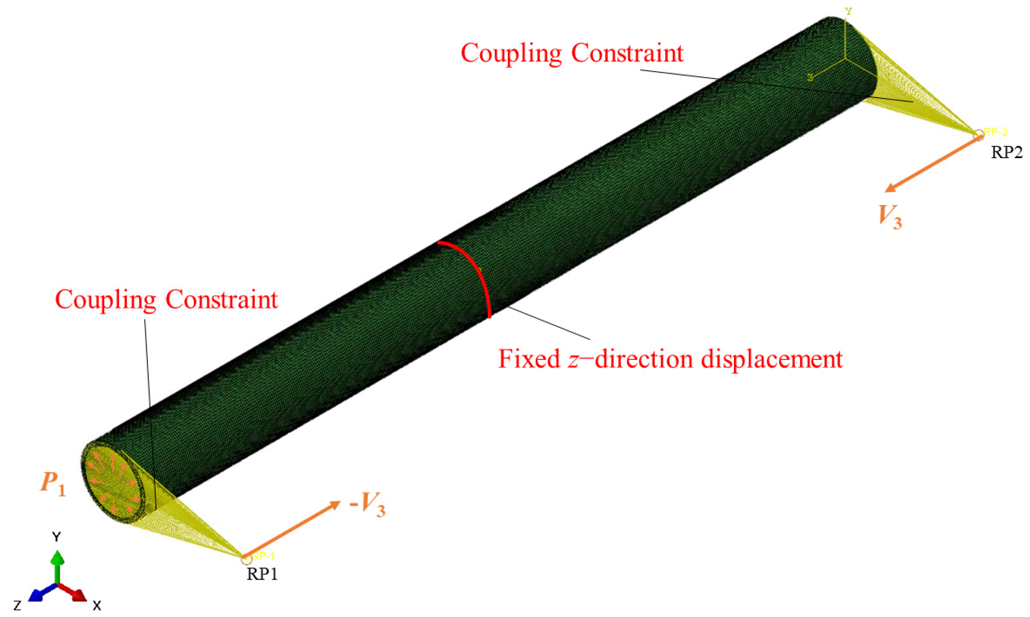
4.1.1. Finite Element Modeling Setup

The finite element model has been suitably simplified according to the assumptions in Section 2 to reduce the computational cost. Table 2 provides the geometric parameters of simplified hose structural components. Other structures, such as the floating body of foam and the outer jacket, have little contribution to the strength of the hose and are, therefore, ignored. The modeling method for self-floating hoses refers to the work of other researchers in modeling flexible pipelines [7,10,26].
The hose with a 900 mm inner diameter and 68 mm wall thickness was modeled using solid elements. Due to its cross-sectional properties as a hyperelastic material, a hybrid formulation mesh (C3D8H) was used for discretization. Reinforcement layers were defined by shell elements (S4R), and embedded cords were simulated by rebar layers. The reinforcement shell was uniformly divided into rebar layers defined along the thickness direction. The following data are required to model the performance of flexible hoses using the steel reinforcement method: layer name, area per bar, spacing (distance between the centers of two cords), material properties, orientation angle, and position of cord layers. The winding diameter of the helical steel wire was 960 mm, the pitch was 100 mm, and the cross-sectional diameter was 12 mm. Given that the cross-sectional scale of the steel wire was much smaller than the axial scale, a very small mesh size was required to discretize a three-dimensional solid model, which greatly increased the number of meshes and the difficulty of convergence. Therefore, the helical steel wire was modeled as a spatial beam element model and discretized using B31 elements. Table 3 summarizes the types of discrete elements with different structures and the number of meshes and nodes. After these components were suitably assembled, the reinforcement layer shell elements and helical steel wire beam elements were embedded into the rubber matrix by embedded element technology in Abaqus, and the simplified model is shown in Figure 13.

4.1.2. Loads and Boundary Conditions

To reduce computational costs, this study used coupling constraints instead of modeling the bending rod, as its stiffness was much greater than that of the rubber hose. As shown in Figure 14, two reference points, RP1 and RP2, were set at both ends of the hose, offset by 2.15 m (initial bending rod arm length) from the centerline of the hose along the x direction. The six degrees of freedom of nodes on the end of the hose were coupled with reference points. A velocity of V3 = 0.1 m/s towards the middle was applied at the reference point, thereby causing the two end section of the rubber hose to bend. To avoid rigid body displacement leading to nonconvergence, the z direction (axial direction) displacement of nodes in the middle section was constrained. To simulate the internal water pressure in the test, a uniformly distributed pressure load of P1 = 0.1 MPa was applied to the inner wall of the hose to prevent potential local buckling.

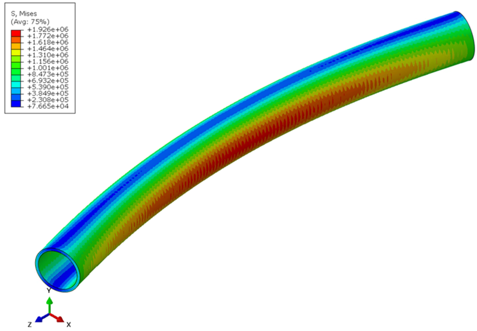
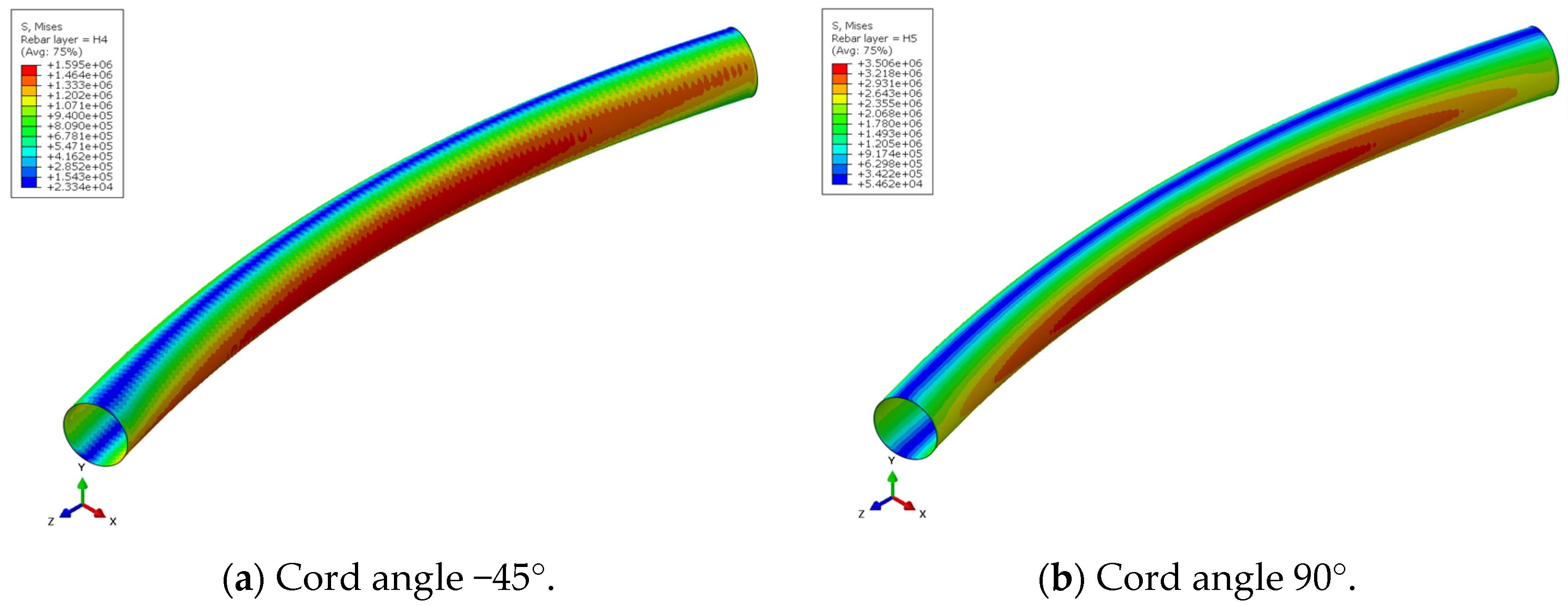
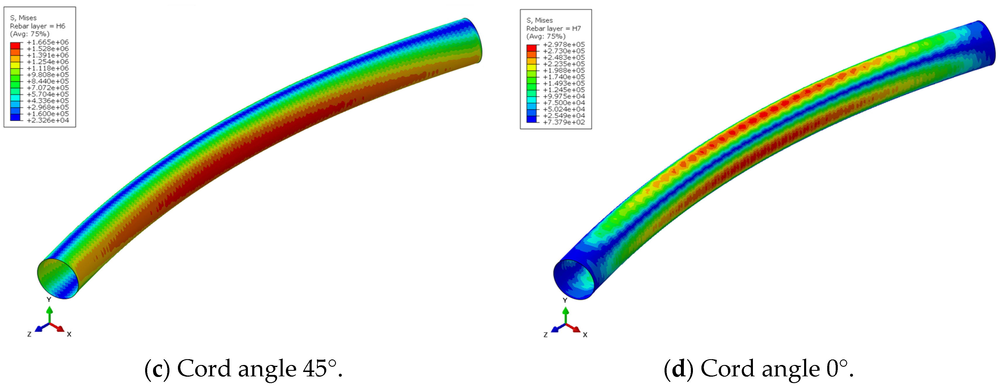
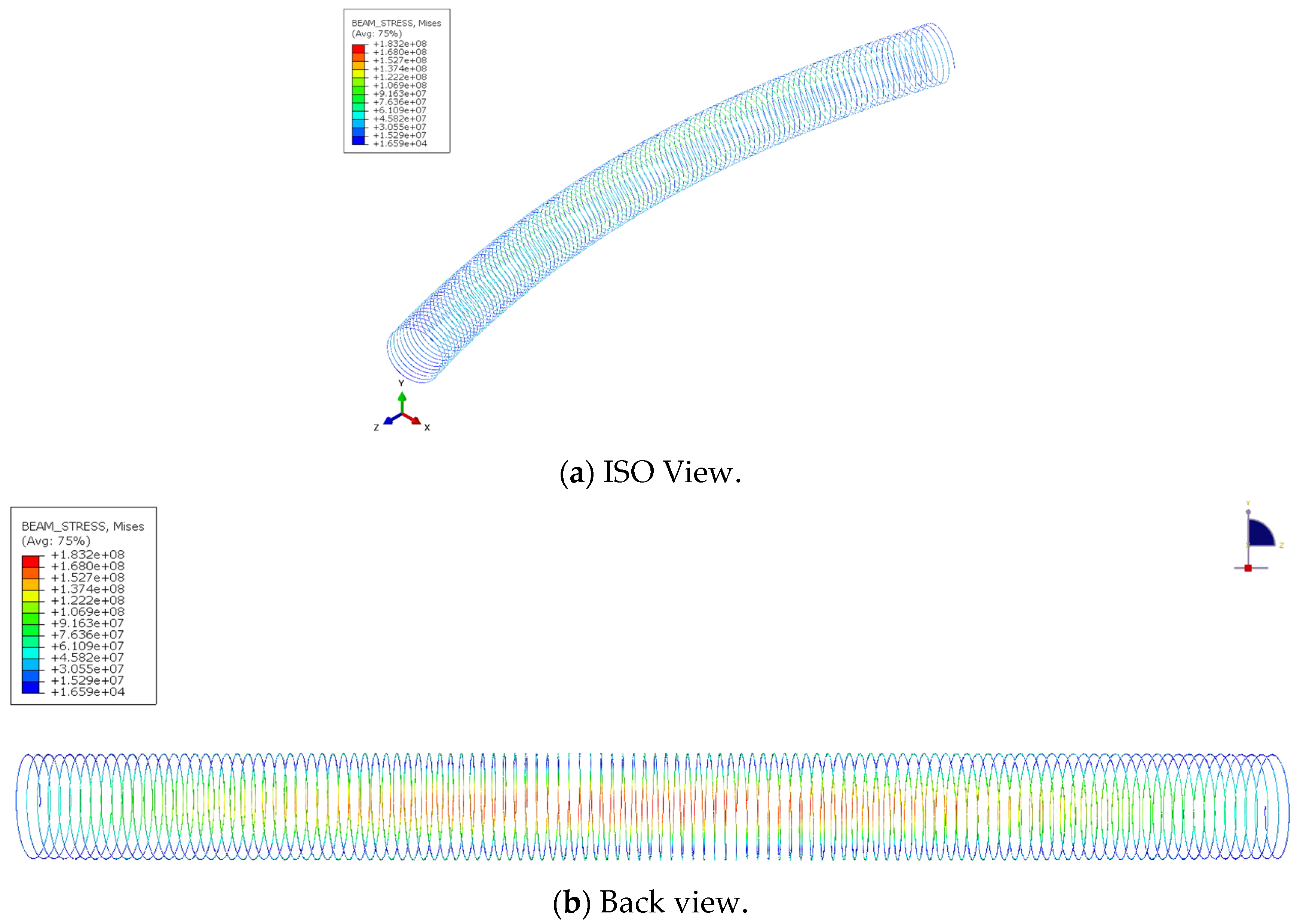
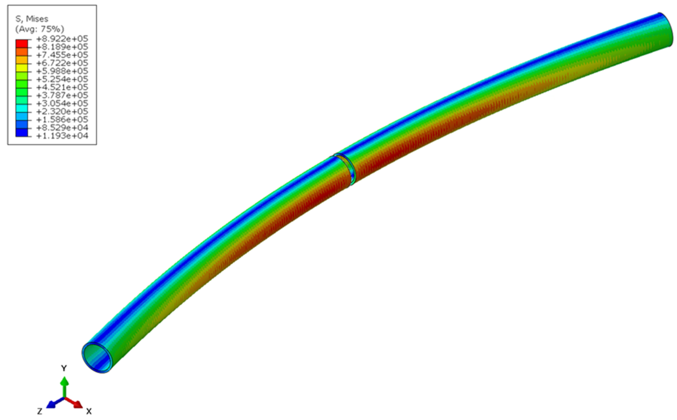
4.1.3. Stress and Deformation

Figure 15, Figure 16 and Figure 17 show the stress contours of the rubber base, cord reinforcement layers, and helical steel wire at a bending angle of 30°. The maximum stress on the rubber matrix was 1.926 MPa, which occurred in the middle of the rubber pipe. The maximum stress values for the four typical cord angle (−45°, 90°, 45°, 0°) ply layers were 1.595 MPa, 3.506 MPa, 1.665 MPa, and 0.2978 MPa, respectively. When the cord angle was close to 0°, the direction of the cord was parallel to the circumferential direction of the pipeline, and the cords could not withstand less bending normal stress loads. To increase the bending stiffness of the hose, it is recommended to align as many cord layers along the pipeline axial direction (cord angle of 90°) as possible.
The maximum stress on the steel wire was 183.2 MPa, which is almost 100 times the maximum value of other structures. However, the high stress on the steel wire is not caused by large bending loads, but mainly to resist cross-sectional deformation and internal pressure during the bending process. To further illustrate this point, Table 4 shows bending stiffness and proportions of different compositions. It can be seen that the rubber matrix and composite reinforcement layers contribute significantly to the total stiffness. Although the modulus of the steel wire is relatively large, its cross-sectional area is very small, so its contribution is relatively small. However, it is not the case that steel wires should be out of the calculation equation. The steel wire is the main component that withstands radial pressure and limits the radial deformation (flattening) of the hose cross-section, which prevents stiffness reduction during large bending deformation. Figure 18 compares the cross-sectional deformation of embedded steel wire hose and non-wire hose during bending. It can be seen that when the steel wire is not embedded, the cross-section of the hose will undergo significant deformation, changing from a circular shape to an approximate elliptical shape, which will result in much smaller bending or buckling loads than the actual values.

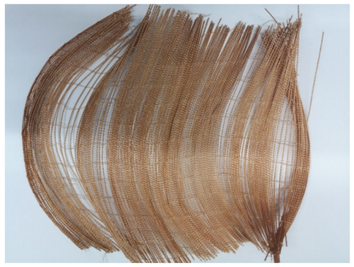
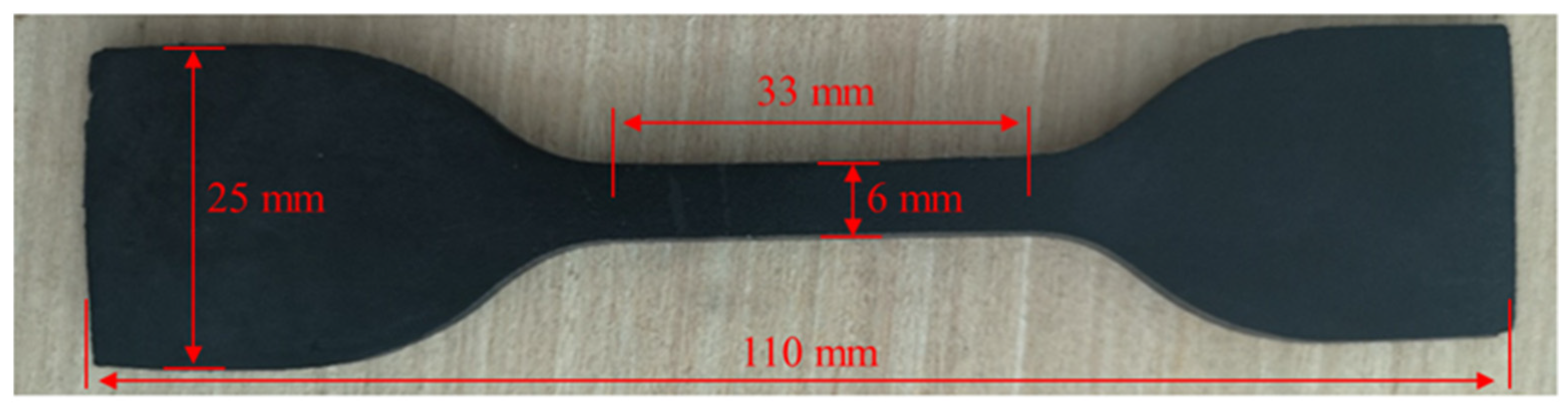
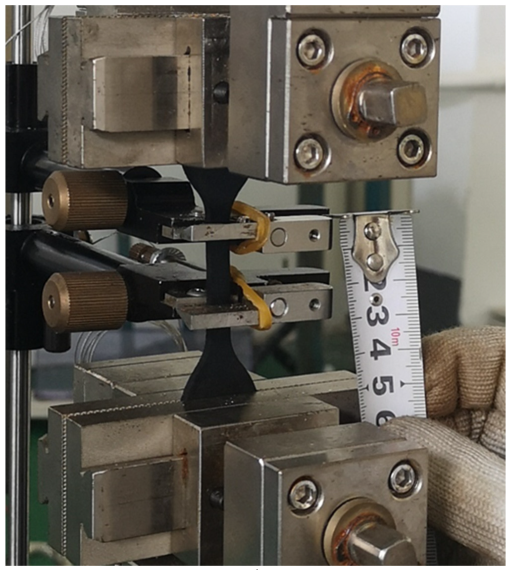
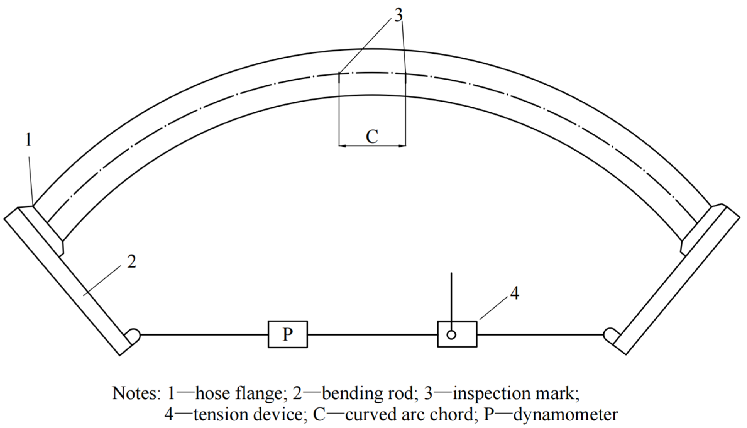
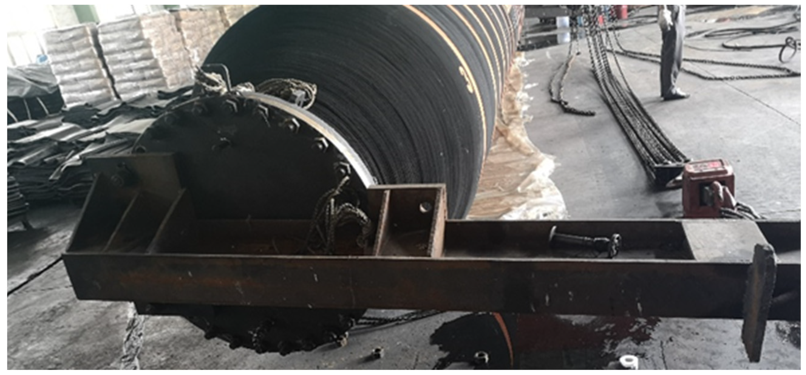
4.2. Hose Bending Test Setup

For finished hoses, their relevant mechanical properties must be measured before leaving the factory to provide a reference for practical applications, and one of the most common test methods is the bending test. According to GB/T 37221-2018 [27], a bending test was performed on a 900 mm × 11,900 mm self-floating hose weighing 7.4 tons using the method shown in Figure 19. The bending condition, minimum bending radius, and bending stiffness of the hose were measured.
The hose to be tested was placed on a relatively smooth base with hose bending rods connected at both ends to facilitate the application of tension by the tensioner to bend the hose. By bending the hose at different angles, mechanical characteristics, such as the bend radius, tension, and torque of the hose, were obtained. Considering the friction between the rubber hose and the ground, the test was divided into two processes: tension and relaxation, with the tension forces recorded, respectively.
Figure 20 and Figure 21 show the test setup at the test site of Jiangsu Huashen Special Rubber Products Co., Ltd. in Danyang, China, for the bending testing of the self-floating hose.

4.3. Comparison

The tensile forces at both ends of the hose are presented in Figure 22, which includes theoretical calculations, FEM calculations, and experimental testing results. Table 5 displays the relative errors. Except for a small bending angle (10°), the theoretical calculation error is less than 8%. The largest calculation error in the first group, −19.47%, is mainly attributed to friction. Although a lubricating film was laid in the testing to reduce the friction between the hose and the ground, due to the heavy weight of the hose, the difference between the friction force and the small angle bending load was not significant, which led to significant calculation errors. In general, test results show a good agreement with theoretical analysis solutions, which also proves the feasibility and credibility of the theoretical model proposed in this study for evaluating the engineering application of offshore hoses. FEM results are generally 20% higher than testing results, indicating that the FE model is biased towards rigidity and conservative in predicting the bending behavior of hoses.

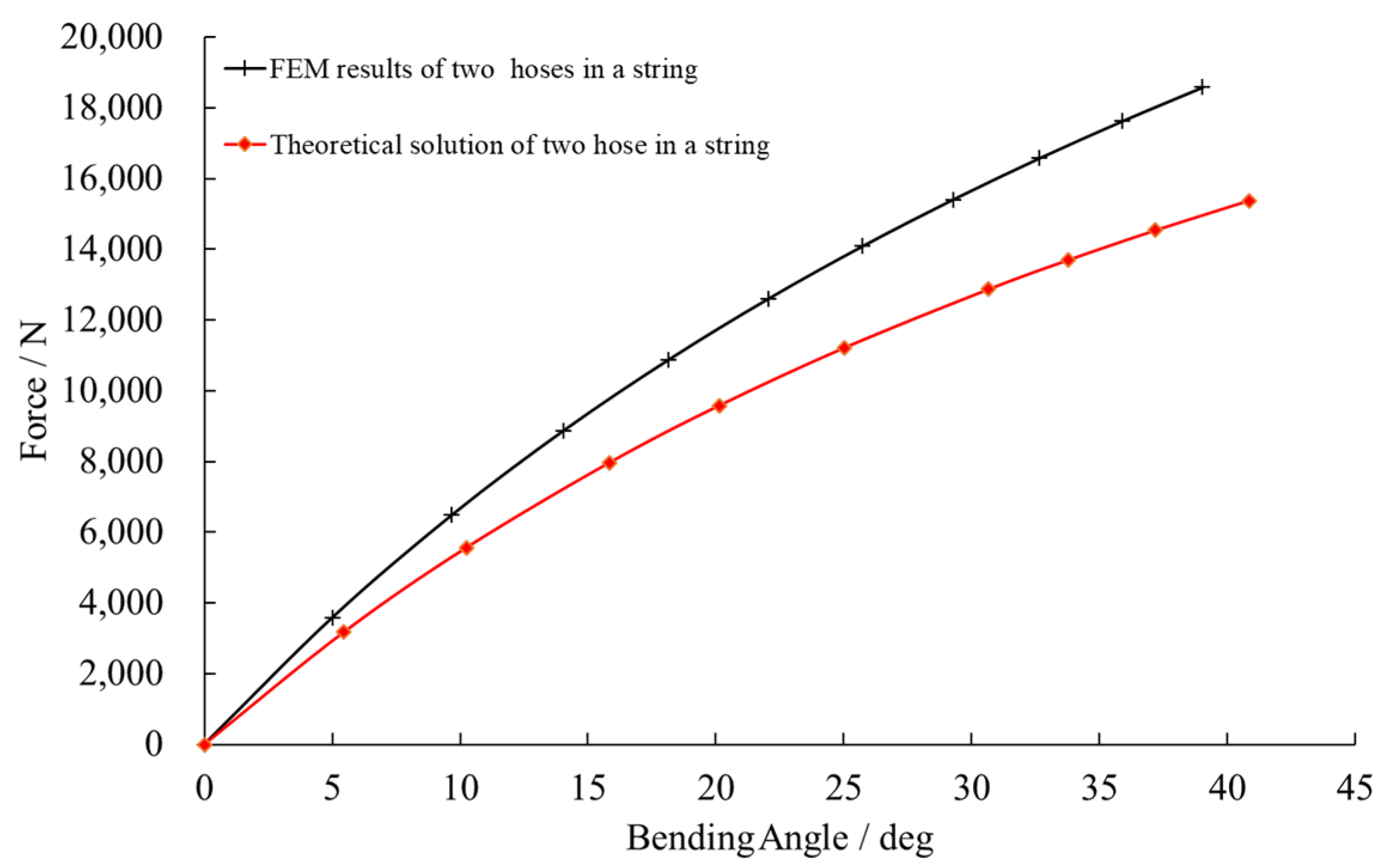
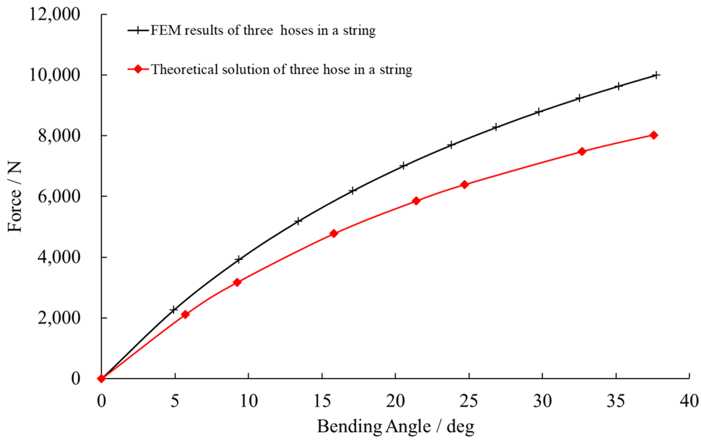
4.4. Hose String Bending

4.4.1. Flange Connection

In Figure 1, it can be seen that the dredging floating hose is typically connected in series using flanges. In Section 4.1, only the bending of a single pipeline was considered, and the stiffness of the flange was assumed to be much greater than that of the rubber hose. Therefore, the flange was not included in the model. When considering the string bending of self-floating rubber hoses, the influence of flanges on the bending stiffness of the pipeline cannot be ignored. Figure 23 illustrates the discretization of the flange using the C3D8R element type and tie constraints of contact surfaces between the flange and the rubber hose to prevent relative slip. To investigate the influence of the number of connected hoses on bending calculation, this study investigated the cases of two hoses in a string and three hoses in a string.

4.4.2. Results

Figure 24 and Figure 25 show the stress results at a 30° bending angle of the hose string. The more connected the pipe sections are, the less bending curvature each rubber hose shares. In addition, it can be concluded that although the rigid flange, to some extent, hinders the deformation of the hose end face, the bent hoses in a string still show an approximate circular arc shape, which also indirectly proves that the beam theory can be used for the calculation of the hose string.
Figure 26 and Figure 27, respectively, show the theoretical and numerical calculation results for the cases of two hoses in a string and three hoses in a string It can be seen that the theoretical solution based on equivalent bending stiffness is still applicable to the case of bending string. The load variation trend between two calculation results is very similar, with a difference of less than 20%, and FEM results are more conservative. This verifies the feasibility of the theoretical method proposed in this study and provides a solution for solving the problem of floating hose string alignment in new products.

5. Conclusions

This study presents general theoretical, numerical, and experimental analyses of the nonlinear bending mechanical behavior of dredging floating hoses. A theoretical solution based on the basic beam theory and equivalent bending stiffness was established, in which the final theoretical bending stiffness was obtained by superimposing the linearly equivalent results of the three main components. The mechanical model proposed in this study can be applied to general marine hose structures, and therefore, it can analytically solve the bending results in hoses with nonlinear reinforcement structures. Through comparative research with relevant testing and FEM results, the basic beam bending theory of flexible hoses that meets engineering requirements has been verified.
Although the results presented in this study can provide effective references for the actual production design of floating hoses, there are still some uncertain engineering factors. Further research is going to consider the changes in the cross-sectional shape of large-diameter hoses without dense steel wire arrangement during bending deformation, which is also important in correcting the bending stiffness. More boundary conditions should be included, such as instantaneous changes in internal fluid pressure under higher pressure. The factors mentioned above will definitely provide more refined predictive modes and more reliable guidance for further designing and verifying the global performance of marine hoses.

Author Contributions

Conceptualization, J.L. (Jingjing Liu) and L.Y.; methodology, J.L. (Jingjing Liu); software, J.L. (Jingjing Liu); validation, J.L. (Jingjing Liu) and L.Y.; investigation, X.L. (Xiaoyan Li) and L.Y; writing—original draft preparation, J.L. (Jingjing Liu) and L.Y.; writing—review and editing, J.L. (Jingjing Liu); supervision, J.L. (Jing Liu); project administration, X.L. (Xiaoyan Li); funding acquisition, L.Y. (Jing Liu). All authors have read and agreed to the published version of the manuscript.

Funding

This work was funded by the Fundamental Research Funds for the Central Universities from the People’s Republic of China.

Data Availability Statement

The raw data supporting the conclusions of this article will be made available by the authors on request.

Acknowledgments

The authors thank Jiangsu Huashen Special Rubber Products Co., Ltd., who have contributed substantially to the completion of this study, for their encouragement and experiment support.

Conflicts of Interest

Authors Xiaoyan Li and Jing Liu were employed by CCCC Guangzhou Dredging Co., Ltd. The remaining authors declare that the research was conducted in the absence of any commercial or financial relationships that could be construed as a potential conflict of interest.

References

  1. Orion Market Research. Global Dredging Hose Market Size, Share and Trends Analysis Report, by Type (Floating Dredge Hose and Non-Floating Dredge Hose) and Forecast, 2020–2026; 2020. Available online: https://www.omrglobal.com/industry-reports/floating-dredging-hose-market (accessed on 24 January 2024).
  2. JSA. JIS F 3995. Rubber Sleeves for Dredge Discharge Pipes; Japanese Standards Association (JSA): Tokyo, Japan, 2000. [Google Scholar]
  3. OCIMF. Guide to Manufacturing and Purchasing Hoses for Offshore Moorings (GMPHOM), 5th ed.; Oil Companies International Marine Forum (OCIMF), Witherby Seamanship International Ltd.: Livingstone, UK, 2009. [Google Scholar]
  4. API. API 17K. Specification for Bonded Flexible Pipe, 3rd ed.; American Petroleum Institute (API): Houston, TX, USA, 2017. [Google Scholar]
  5. ISO 28017:2018; Rubber Hoses and Hose Assemblies, Wire or Textile Reinforced, for Dredging Applications. International Organization for Standardization (ISO): Geneva, Switzerland, 2018.
  6. Amaechi, C.V.; Wang, F.C.; Jae, I.A.; Aboshio, A.; Odijie, A.C.; Ye, J.Q. A literature review on the technologies of bonded hoses for marine applications. Ships Offshore Struct. 2022, 17, 2819–2850. [Google Scholar] [CrossRef]
  7. Tonatto, M.L.P.; Tita, V.; Forte, M.M.C.; Amico, S.C. Multi-scale analyses of a floating marine hose with hybrid polyaramid/polyamide reinforcement cords. Mar. Struct. 2018, 60, 279–292. [Google Scholar] [CrossRef]
  8. Zhou, Y.; Duan, M.L.; Ma, J.M.; Sun, G.M. Theoretical analysis of reinforcement layers in bonded flexible marine hose under internal pressure. Eng. Struct. 2018, 168, 384–398. [Google Scholar] [CrossRef]
  9. Gao, P.; Li, C.C.; Wang, H.; Gao, Q.; Li, Y. A simplified method to predict the crush behavior of offshore bonded rubber hose. J. Mar. Sci. Eng. 2023, 11, 406. [Google Scholar] [CrossRef]
  10. Gao, Q.; Zhang, P.; Duan, M.; Yang, X.B.; Shi, W.; An, C.; Li, Z. Investigation on structural behavior of ring-stiffened composite offshore rubber hose under internal pressure. Appl. Ocean Res. 2018, 79, 7–19. [Google Scholar] [CrossRef]
  11. Bedford, A.; Liechti, K.M. Mechanics of Materials, 2nd ed.; Springer: Cham, Switzerland, 2020; pp. 361–367. [Google Scholar]
  12. Hackett, R.M. Strain-Energy Functions. In Hyperelasticity Primer, 1st ed.; Springer: Cham, Switzerland, 2016; pp. 19–25. [Google Scholar]
  13. Rivlin, R.S. Large elastic deformations of isotropic materials IV. further developments of the general theory. Philos. Trans. R. Soc. Lond. Ser. A Math. Phys. Sci. 1948, 241, 379–397. [Google Scholar]
  14. Mooney, M. A theory of large elastic deformations. J. Appl. Phys. 1940, 11, 582–592. [Google Scholar] [CrossRef]
  15. Yeoh, O.H. Characterization of elastic properties of carbon-black-filled rubber vulcanizates. Rubber Chem. Technol. 1990, 63, 792–805. [Google Scholar] [CrossRef]
  16. Ogden, R.W. Large deformation isotropic elasticity: On the correlation of theory and experiment for incompressible rubberlike solids. Proc. R. Soc. Lond. Ser. A 1972, 328, 567–583. [Google Scholar] [CrossRef]
  17. Arruda, E.M.; Boyce, M.C. A three-dimensional constitutive model for the large stretch behavior of rubber elastic materials. J Mech. Phys. Solids 1993, 41, 389–412. [Google Scholar] [CrossRef]
  18. Gent, A.N. A new constitutive relation for rubber. Rubber Chem. Technol. 1996, 69, 59–61. [Google Scholar] [CrossRef]
  19. Kobelev, V. Principles of Spring Design. In Durability of Springs, 2nd ed.; Springer: Cham, Switzerland, 2021; pp. 1–9. [Google Scholar]
  20. Teodorescu, P.P. Mathematical Models in Mechanics of Deformable Solids. In Treatise on Classical Elasticity. Springer, Theory and Related Problems, 1st ed.; Springer: Dordrecht, London, UK, 2013; pp. 138–155. [Google Scholar]
  21. Halpin, J.C.; Tsai, S.W.; Halpin, J.C.; Tsai, S.W. Effect of Environmental Factors on Composite Materials; Air Force Technical Report AFML-TR 67-423; 1967. Available online: https://www.semanticscholar.org/paper/Effects-of-Environmental-Factors-on-Composite-Halpin/1a8502fad082b55755965085de1b6dad8edcbca2 (accessed on 24 January 2024).
  22. Yi, X.S.; Du, S.; Zhang, L.T. Composite Structure Design and Analysis. In Composite Materials Engineering, Volume 1: Fundamentals of Composite Materials, 1st ed.; Chemical Industry Press: Beijing, China, 2018; pp. 383–395. [Google Scholar]
  23. Yu, L.; Li, Y.; Xia, L.J.; Ding, J.H.; Yang, Q. Research on mechanics of ship-launching airbags I-material constitutive relations by numerical and experimental approaches. Appl. Ocean Res. 2015, 52, 222–233. [Google Scholar] [CrossRef]
  24. ISO 23529:2016; Rubber–General Procedures for Preparing and Conditioning Test Pieces for Physical Test Methods. Physical tests. International Organization for Standardization: Geneva, Switzerland, 2016.
  25. GB/T 528-2009; Rubber, Vulcanized or Thermoplastic—Determination of Tensile Stress-Strain Properties. National Standard Committee Rubber Rubber Physical and Chemical Test Methods Technical Committee: Shenyang, China, 2009.
  26. Amaechi, C.V.; Chesterton, C.; Butler, H.O.; Gu, Z.; Odijie, A.C.; Wang, F.; Hou, X.; Ye, J. Finite element modelling on the mechanical behaviour of marine bonded composite hose (MBCH) under burst and bollapse. J. Mar. Sci. Eng. 2022, 10, 151. [Google Scholar] [CrossRef]
  27. GB/T 37221-2018; Self-Floating Rubber Hoses and Hose Assemblies for Dredging Applications and Rubber and Plastics Hoses and Tubing—Measurement of Flexibility and Stiffness—Part 1: Bending Tests at Ambient Temperatures. China Petroleum and Chemical Industry Federation: Beijing, China, 2018.
Figure 1. Engineering application of dredging hoses (from http://www.hlrubber.net/about/10.html (accessed on 24 January 2024)).
Jmse 12 00421 g001
Figure 2. The theoretical, numerical, and experiment analysis flowchart of hose bending.
Jmse 12 00421 g002
Figure 3. Outward appearance of floating hose.
Jmse 12 00421 g003
Figure 4. Layout of composite hose body (longitudinal profile) [10].
Jmse 12 00421 g004
Figure 5. Bending deformation of hose beam. (a) Hose beam and pulling load. (b) Bending of a straight beam under moment only (c) Curved beam bending.
Jmse 12 00421 g005
Figure 6. Force loading on helical cylindrical spring.
Jmse 12 00421 g006
Figure 7. Resolution of moments into normal and tangential components.
Jmse 12 00421 g007
Figure 8. Cord-rubber composite reinforcement layer. (a) Composite layers. (b) Coordinate system transformation.
Jmse 12 00421 g008
Figure 9. Synthetic tire cord fabrics forming the middle layer that reinforces the hose.
Jmse 12 00421 g009
Figure 10. Rubber uniaxial tensile sample.
Jmse 12 00421 g010
Figure 11. Rubber specimens clamped on uniaxial tensile testing machine.
Jmse 12 00421 g011
Figure 12. Rubber stress–strain relationship.
Jmse 12 00421 g012
Figure 13. Simplified hose FE model.
Jmse 12 00421 g013
Figure 14. Loads and boundary conditions.
Jmse 12 00421 g014
Figure 15. Stress contour of rubber matrix.
Jmse 12 00421 g015
Figure 16. Stress contours of cord reinforcement layers.
Jmse 12 00421 g016aJmse 12 00421 g016b
Figure 17. Stress contours of helical steel wire.
Jmse 12 00421 g017
Figure 18. Cross−section deformation at the midpoint of the hose (bending angle of 30°).
Jmse 12 00421 g018
Figure 19. Bending test method.
Jmse 12 00421 g019
Figure 20. Floating hose for testing.
Jmse 12 00421 g020
Figure 21. Connection between bending rod and floating hose.
Jmse 12 00421 g021
Figure 22. Comparison of bending tension of rubber hoses.
Jmse 12 00421 g022
Figure 23. Flange connection.
Jmse 12 00421 g023
Figure 24. Stress contour of two hoses in a string.
Jmse 12 00421 g024
Figure 25. Stress contour of three hoses in a string.
Jmse 12 00421 g025
Figure 26. Comparison of FEM results and theoretical solutions for two hoses in a string.
Jmse 12 00421 g026
Figure 27. Comparison of FEM results and theoretical solutions for three hoses in a string.
Jmse 12 00421 g027
Table 1. Material parameters.
MaterialParameters
RubberC10 = 9.68 MPa; C20 = 0.46 MPa; C30 = 0.21 MPa
Steel (Helical wire)Young’s modulus = 140 GPa; Poisson’s ratio = 0.3
Steel (Flange)Young’s modulus = 206 GPa; Poisson’s ratio = 0.3
CordTensile modulus = 1313 MPa; Poisson’s ratio = 0.3
Table 2. Geometric parameters of the analyzed hose.
ParameterValue
Nominal inner radius/mm450
Outer radius/mm518
Winding angle of 1st reinforcement layer[90°/45°/0°/−45°/90°/45°/0°]
Winding angle of 2nd reinforcement layer[45°/−45°]
Mean helix radius/mm480
Helix wire diameter/mm12
Pitch of helix/mm100
Length of the model/mm11,900
Table 3. Mesh details.
ComponentElement TypeNo. of ElementsNo. of Nodes
Rubber matrixC3D8H77,224116,130
Reinforcement (2 layers)S4R42,55242,660
Reinforcement (14 layers)S4R37,82437,920
Helical steel wireB3111,86711,868
Flange (string bending)C3D8R14562496
Table 4. Contribution of the bending stiffness of compositions.
Composition(EI)rubber(EI)reinforcement(EI)wire(EI)total
Value/N·m2953,632903,6525841,857,868
Proportion51.33%48.64%0.03%-
Table 5. Calculation error.
AngleForce by TheoryForce by FEMAverage Force by TestError 1Error 2
(1)(2)(3)((1)–(3))/(3)((2)–(3))/(3)
10°11,758 14,35814,602−19.47%−1.67%
25°26,597 32,31627,578−3.56%17.18%
35°35,070 42,27535,467−1.12%19.20%
45°42,639 50,72443,927−2.93%15.47%
50°46,138 54,36745,2232.02%20.22%
55°49,460 58,41247,8563.35%22.06%
60°52,631 62,94757,200−7.99%10.05%
Disclaimer/Publisher’s Note: The statements, opinions and data contained in all publications are solely those of the individual author(s) and contributor(s) and not of MDPI and/or the editor(s). MDPI and/or the editor(s) disclaim responsibility for any injury to people or property resulting from any ideas, methods, instructions or products referred to in the content.

