Article

Numerical Simulation of Offshore Suction Bucket Foundation Pullout Characteristics under Undrained Conditions

1
Ocean College, Zhejiang University, Zhoushan 316021, China
2
Yangjiang Offshore Wind Power Laboratory, Yangjiang 529500, China
*
Author to whom correspondence should be addressed.
J. Mar. Sci. Eng. 2024, 12(3), 419; https://doi.org/10.3390/jmse12030419
Submission received: 22 January 2024 / Revised: 21 February 2024 / Accepted: 23 February 2024 / Published: 27 February 2024
(This article belongs to the Section Ocean Engineering)

Abstract

:
The suction bucket jacket foundation is widely regarded as a crucial solution for constructing offshore wind farms in water depths ranging from 30 m to 50 m. When subjected to complex loads, the bucket primarily relies on vertical movement to withstand the corresponding loads. This paper investigates the undrained pullout characteristics of the bucket foundation through numerical simulation while keeping its weight constant. This study examined how the pullout capacity of the suction bucket jacket foundation is affected by the aspect ratio and soil conditions. It revealed the changing patterns of bucket–soil frictional resistance and suction during the undrained pullout process, along with their contributions to the pullout capacity of the foundation. The results indicate that the peak pullout load of the bucket increases with decreasing L/D, and the response is more pronounced in soft clay. The frictional resistance changes from upward to downward with increasing displacement, with the maximum frictional resistance occurring at the base of the foundation. The lower part of the footing has a faster response. The suction force increases with displacement, and the proportion of suction force to peak pullout tends to increase as L/D decreases. The soil failure displacement corresponding to the occurrence of the peak pullout load of the foundation lags behind the displacement at which the frictional resistance of the bucket wall stabilizes.

1. Introduction

Energy is a crucial driving force for advancing human society. Currently, countries worldwide are gradually shifting towards a modern energy system that relies more on clean and renewable energy sources like wind and solar power.
Offshore wind power has become a focal point in the energy transition for coastal nations due to its high operational efficiency, proximity to load centers, minimal land resource utilization, and suitability for large-scale development. According to data released by the Global Wind Energy Council [1], the global installed capacity of offshore wind turbines reached 64.3 GW at the end of 2022 and continues to show a trend of rapid and sustained growth.
The foundation of offshore wind turbines can account for up to 35% of the installation cost. Therefore, the design of the foundation plays a crucial role in the economics of the project [2]. It is important to select the appropriate form of foundation for the development of offshore wind farms. The suction bucket jacket foundation has numerous advantages for offshore wind energy. It is characterized by high vertical stiffness, excellent stability, strong environmental adaptability, ease of installation, and an absence of noise pollution. Its application in the offshore wind energy sector is becoming increasingly widespread [3,4,5,6,7,8]. The suction bucket jacket foundation is considered a significant alternative to traditional single pile foundations and pile-supported jacket foundations for constructing offshore wind farms in water depths ranging from 30 m to 50 m [9]. Figure 1 shows successful applications of the foundation in Chinese offshore wind farms.
According to reference [10], the foundation relies mainly on the vertical displacement of the bucket to withstand complex loads. Houlsby et al. [11] confirmed this finding in their study. Kim et al. [12] conducted centrifuge model experiments and found that the tripod suction bucket foundation exhibits minimal rotational response, confirming that its failure mode is uplift rather than overturning. Therefore, studying the pullout capacity of suction bucket foundations is crucial to ensuring the safe service of offshore wind turbine suction bucket jacket foundations.
Hung et al. [13] found that the pullout capacity of a bucket in saturated sand is higher than in dry sand. Their study revealed that suction is generated within the bucket in saturated sand, leading to an increase in the foundation’s pullout capacity. Based on this, they proposed an equation to assess the pullout capacity of the bucket under suction and non-suction conditions. In their study, Hong et al. [14] investigated the influence of drainage conditions on the pullout characteristics of buckets in sand through physical model experiments under constant gravity conditions. They introduced the concept of a drainage factor and classified the drainage conditions of suction bucket foundations under peak pullout loads based on different drainage factors. Vincent et al. [15] conducted model experiments to investigate the effect of pullout rate on the pullout capacity of buckets in sand. They proposed calculation formulas for the pullout capacity of buckets under drained and undrained conditions based on the experimental results. In their study, Ssenyondo et al. [16] examined how the pullout capacity of a bucket in sand is affected by embedment depth. They achieved this by altering the bucket length while keeping the diameter constant. They developed a simplified method that accurately predicts the pullout capacity of a bucket with varying L/D ratios. In numerical simulations, scholars often model soil as elastic–plastic materials, such as Duncan-Chang, Tresca, or Mises, and conduct load analysis for suction bucket foundations [17,18]. In their study, Shen et al. [19] used a bounding surface model to analyze the response of buckets to vertical pullout loads. They conducted a parameter study to investigate the influence of the pullout rate on the tension load–displacement curve. Asakereh et al. [20] studied how soil cohesion, relative density, and soil Young’s modulus affect the pullout capacity of cylindrical foundations. The study found that the pullout capacity of cylindrical foundations increases with an increase in these variables. They proposed an equation for assessing the pullout capacity of the bucket based on these findings.
In summary, there is currently limited research on the pullout capacity of suction bucket jacket foundations. Further studies are needed to evaluate this capacity. This study kept the suction bucket foundation mass constant while varying the length and diameter of the bucket to achieve changes in the aspect ratio, representing full-scale alterations of the suction bucket foundation. This approach aims to achieve optimal results within the analyzed range while evaluating the load-bearing capacity of the bucket. The analysis includes investigating the ultimate pullout capacity, frictional resistance, and suction variations during the uplift process of the bucket.

2. Numerical Simulation

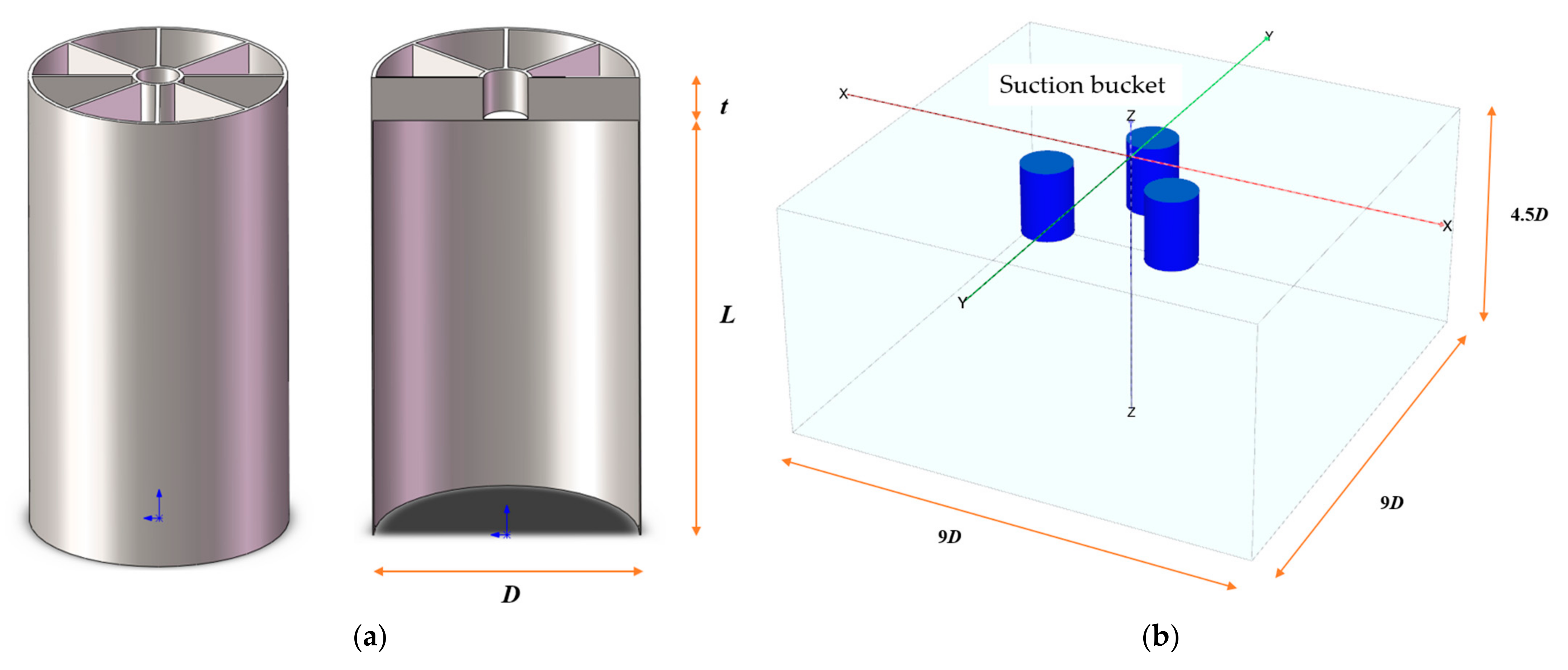
2.1. Finite Element Model

The prototype bucket design model of the suction bucket foundation used in real engineering is shown in Figure 2a. The suction bucket foundation is a steel structure with stiffeners at the top. Plate elements are used to simulate the bucket in the finite element model. The Von Mises yield criterion was applied, with a Young’s modulus of 210 GPa, a Poisson’s ratio of 0.3, and a density of 7850 kg/m3 for the material. The computational analysis of the finite element model is shown in Figure 2b. To simulate the enhanced stiffness of the top of the suction bucket by the reinforced plate in the prototype bucket and to simplify the model, the finite element model used a top plate with increased thickness instead of the top of the prototype bucket. A thorough analysis of the boundary effects on the results was conducted to establish simple and rational boundary conditions [21], while ensuring computational accuracy. First, the radial boundaries are set to 10D, 9D, 8D, 7D, and 6D, respectively, for calculation. The analysis revealed that changes in the radial boundary had minimal impact on the results, with results nearly identical for radial boundaries set at 9D and 10D, leading to the determination of the radial boundary as 9D. Subsequently, the depth direction boundary was adjusted to 5.5D, 5D, 4.5D, 4D, 3.5D, and 3D for calculations. The results indicated that the calculation results started to deviate when the depth direction boundary was less than 4D. As a result, the depth boundary was determined to be 4.5D. To simulate the soil plug of the undrained pullout process, the inner side of the suction bucket foundation was bound to the foundation soil [15], while the outer side was modeled with frictional contact that cannot detach in the normal direction [22]. The soil’s upper surface was free, and a 30 m head was applied. Only vertical displacement was permitted on the side surfaces, and the bottom was entirely fixed. The spacing between the buckets was set to 2.2 times the diameter of the bucket in order to disregard the combined impact of the grouped buckets [21].
The study kept the weight of the bucket constant while varying L/D by changing the length and diameter of the bucket. The objective was to investigate how changes in D and L impact the foundation’s pullout capacity. Table 1 presents the specific dimensions of five numerical models with different L/D ratios.

2.2. Soil Material Model

To investigate the pullout characteristics of a suction bucket foundation under different soil conditions, this study considers two types of soils: medium-dense saturated sand and soft clay. The mechanical properties of sand are simulated using the Mohr–Coulomb model. The undrained shear strength of saturated sand is modeled using the cohesive strength parameter. The internal friction angle of the sand can be estimated using the equation [16]:
φ = 26 ° + 10 D r + 0.4 C u + 1.6 l o g   ( D 50 )
where Dr is the relative density, Cu is the uniformity coefficient, and D50 is the mean particle size of the sand. The main parameters of the sand material are shown in Table 2.
For the soft clay foundation, the hardening soil model is used to simulate its mechanical properties. This model is a second-order constitutive model that belongs to the hyperbolic elastic model. It takes into account shear hardening, compression hardening, and stress-dependent stiffness, which allows the simulation of irreversible strain caused by principal deviatoric loading and irreversible compressive deformation under principal compression conditions. The main parameters of the soft clay material are shown in Table 3.

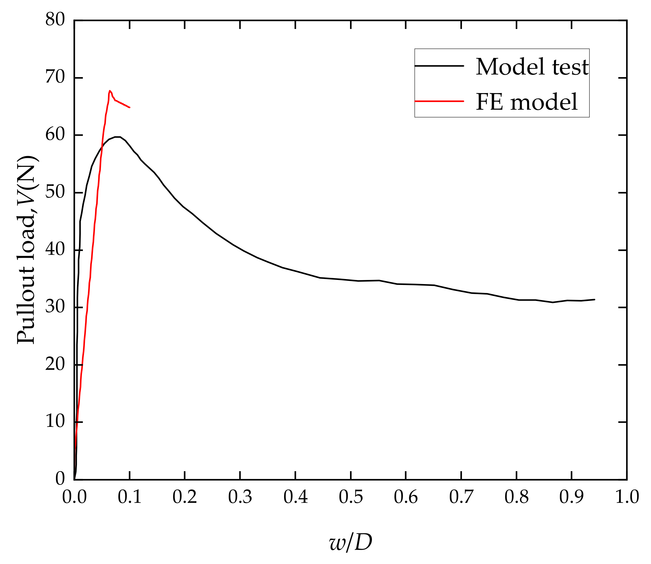
2.3. Validation of the Numerical Model

Numerical analysis employs a three-step approach to simulate the pullout behavior of the suction bucket. First, an initial soil stress field is generated. Next, the bucket is installed at the specified location. The installation process neglects undrained behavior to consider long-term effects while activating the bucket and the bucket–soil contact. Finally, a uniform force or displacement is applied to the bucket foundation to simulate bucket foundation pullout [13].
To verify the accuracy of the numerical model, we conducted a comparative analysis with the physical model test performed by Hong et al. [14]. Hong’s experiment was conducted on loose sandy soil with a bucket diameter of 150 mm, a length of 150 mm, a side wall thickness of 1 mm, and a top wall thickness of 5 mm. The bucket was uniformly lifted at a speed of 2.5 mm/s. As shown in Figure 3, the finite element simulation modeled the uplift process of 0.1D for this setup. The results show a peak pullout load error within 10%, which occurs around 0.08D. The results of the physical model test indicate that the finite element estimation of the pullout capacity is accurate, supporting further research.

3. Results and Discussion

3.1. Study on the Pullout Capacity of the Bucket

By applying the same uplift velocity displacement to buckets with different L/D ratios, load–displacement curves are obtained that allow for analysis of their pullout characteristics. The required pullout rate can be determined by the drainage factor. According to the study by Hong et al. [14], to simulate the uplift of a bucket under undrained conditions, the drainage factor (Fd) must be equal to or greater than 1. The drainage factor is calculated using the following equation:
F d = V p V w
V w = k × u s o ( l i d ) u s o ( t i p ) γ w × L d
where Vp is the pullout rate of the bucket; Vw is the inflow velocity; k is the soil permeability coefficient; γw is the unit weight of water; Ld is the drainage length; uso(lid) is the peak suction pressure under the lid of the suction bucket; and uso(tip) is the peak suction pressure at the tip of the bucket.
This study analyzes the pullout capacity of the suction bucket jacket foundation under undrained conditions with a pullout rate of 0.25 m/s, satisfying the condition Fd ≥ 1. Figure 4 shows the uplift load–displacement curves in medium-dense sand for buckets with different L/D ratios. The pullout displacement (w) is normalized to the suction bucket foundation diameter (D). The pullout load–displacement curves for different L/D ratios show similar trends. In the initial stage, the pullout resistance increases rapidly with displacement and then gradually decreases after reaching its peak. This is consistent with previous research [23,24,25]. The phase before the appearance of the maximum pullout force is considered the pre-failure phase, and the phase after the appearance of the maximum pullout force is considered the post-failure phase. The displacement at which the maximum pullout force occurs is referred to as the failure displacement. The maximum pullout force and failure displacement for each bucket foundation are shown in Table 4.
Combining Figure 4 and Table 4, it can be observed that under the condition of constant bucket mass, smaller L/D results in a larger peak pullout load and a higher initial stiffness. From L/D = 1.4 to L/D = 0.6, the increase in peak pullout load is 4.4%. This is due to the fact that during the undrained pullout process, the failure mode of the foundation soil is overall failure. The influence of the soil below the bottom of the bucket on the pullout response is significant. As L/D decreases, the area of soil below the bottom of the foundation increases, resulting in a larger peak pullout load at the point of soil failure. In addition, at larger L/D ratios, the undrained shear strength of the soil below the suction bucket foundation is higher, making it less susceptible to yielding in the simulation, resulting in larger vertical displacements at the point where the peak pullout load is reached.
In soft clay, the bucket foundation pullout load–displacement curves for various L/D ratios are shown in Figure 5. The maximum pullout load and soil failure displacement for each suction bucket foundation are shown in Table 5.
Combining Figure 5 and Table 5, it can be observed that in soft clay, the pullout load–displacement curves of the suction bucket foundation show a similar trend to those in sandy soil. The patterns of peak pullout loads and soil failure displacements are also similar to those in sandy soil. However, under identical conditions except for soil type, the bucket’s pullout capacity is greater in soft clay than in sandy soil. This finding is consistent with practical engineering experience [26]. From L/D = 1.4 to L/D = 0.6, the ultimate pullout capacity of the bucket shows a significant increase of 29.6%, which is much larger than the increase observed in sandy soil. Therefore, in soft clay, maintaining the same mass of the suction bucket foundation while reducing its L/D has a significant impact on increasing the pullout capacity of the foundation in suction bucket jacket foundation applications.

3.2. Study of the Frictional Resistance of the Bucket

This section investigates the frictional resistance experienced by the bucket foundation during the pullout process under different L/D ratios. Due to setting the inner side of the suction bucket foundation in contact with the soil to simulate the soil plug during the undrained uplift process, the internal soil and the bucket can be considered as a whole [15]. Therefore, this study specifically analyzes the distribution of frictional resistance on the outer wall of the bucket. The distribution of frictional resistance on the outer wall of the bucket under different L/D ratios in sandy soil is shown in Figure 6. The elevation (h) is normalized based on the length of the bucket (L), with the top of the bucket foundation defined as 0 m. The direction of frictional resistance is considered positive if it is upward.
In sandy soil, the distribution of frictional resistance on the outer wall of the bucket foundation under different L/D ratios shows a similar trend. In the initial stage of the pullout, the frictional resistance acting on the bucket foundation is upward, and the maximum frictional resistance occurs at the base of the foundation. As the upward displacement of the foundation increases, the frictional resistance acting on the outer wall of the bucket gradually changes from upward to downward. During this process, the lower part of the foundation exhibits a faster response speed. This is because the lower part of the foundation experiences greater soil pressure, resulting in more significant changes in frictional resistance per unit displacement. During the pullout process from 0.01D to 0.02D, there is a situation where the upper frictional resistance of the bucket foundation is directed upward while the lower frictional resistance is directed downward. This is because the stiffness of the upper soil is less than that of the lower soil. When only gravity is acting, the upper soil experiences greater settlement deformation due to the frictional force between the bucket and the soil. When the lower soil returns to a neutral position without friction, the upper soil still maintains a certain amount of settlement deformation, similar to previous research findings [27].
After a certain displacement, the distribution curve of frictional resistance on the outer wall of the bucket changes from a “C” shape to a straight line that gradually increases from top to bottom and tends to stabilize. After the soil is destroyed, the soil surrounding the suction bucket foundation loses its ability to provide vertical support. Frictional force changes from static to dynamic, and at this point, the frictional force mainly depends on the effective soil pressure at the location. The uplift displacements when the frictional resistance on the outer wall of the bucket stabilizes for different L/D values are shown in Table 6. This is different from the soil failure displacement at the occurrence of the maximum uplift load discussed in Section 3.1, which shows a lagging trend. This is due to the influence of suction, which will be further analyzed in Section 3.3.
In soft clay, the distribution of frictional resistance on the outer wall of the bucket foundation at different L/D ratios is shown in Figure 7. The elevation (h) is normalized based on the length of the bucket (L). In soft clay, the distribution of frictional resistance on the outer wall of the bucket follows a similar trend to that in sandy soil. However, in soft clay, the maximum frictional resistance is significantly higher than in sandy soil, and the distribution curve fluctuates more as the frictional resistance tends to stabilize. This difference is due to the use of distinct soil material models for sandy and soft clay soils.

3.3. Suction Pressure Study of a Bucket

Using the example of the pullout of a bucket in soft clay under undrained conditions, the variation in the suction pressure during the pullout process is studied for different L/D ratios. Figure 8 shows the changes in pore water pressure at the lower part of the bucket lid for various L/D ratios. The variations in pore water pressure characterize the variations in suction pressure. It can be observed that the suction pressure gradually increases during the pullout process of the suction bucket foundation until soil failure. Combining the changes in resistance to pullout, including the weight of the suction bucket, the internal weight of the soil plug, the frictional force along the bucket wall, and the suction force, reveals their contributions to resistance to pullout during the pullout process. Among these factors, the suction force at the lower part of the bucket lid is a major influencing factor, which is influenced by factors such as drawdown rate, drainage length, and hydraulic conductivity [28].
When the bucket is pulled out, shear failure occurs in the soil surrounding the bucket wall, but at this point, the suction pressure has not reached yield [29]. As a result of the shear failure and the reduction in contact area, the frictional force decreases, while the suction force continues to increase until tensile failure occurs. Table 7 shows the vertical displacement and suction pressure corresponding to tensile failure. The data shows that the vertical displacement of the suction bucket during tensile failure is equivalent to the soil failure displacement observed when the bucket foundation reaches its maximum pullout load in Section 3.1. This also explains the phenomenon observed in Section 3.2: the soil failure displacement at the peak pullout load lags behind the displacement as the bucket wall frictional resistance stabilizes.
The suction force is generated by converting the pore water pressure at the bottom of the suction bucket’s lid. The suction force can be estimated by multiplying the pore water pressure by the cross-sectional area of the suction bucket lid [14]. Figure 9 shows a comparison between the peak pullout load and the corresponding suction force for the suction bucket at different L/D ratios. The data visually demonstrate the impact of the suction force at the bottom of the suction bucket lid on the peak pullout load. At L/D = 1.4, suction force accounts for 38.3% of the peak pullout load, and this proportion increases as L/D decreases. At L/D = 0.6, suction force accounts for over 50% of the peak pullout load. The reason for this is that reducing the L/D ratio decreases the frictional resistance between the suction bucket and the soil, resulting in a higher proportion of suction force in the peak pullout load.

4. Conclusions

This study examines the pullout capacity of a bucket under undrained conditions through numerical simulation. The study analyzed the impact of the aspect ratio (L/D) and soil conditions on the pullout capacity of bucket foundations while maintaining constant foundation mass. The study analyzed the variations in bucket–soil frictional resistance and suction force during the foundation pullout process, as well as their contributions to the foundation’s pullout capacity. The main conclusions are:
(1)
The behavior of the suction bucket during pullout in both sand and clay shows a similar trend. Initially, the pullout resistance rapidly increases with displacement, reaching a maximum value before gradually decreasing with further displacement. This behavior is characterized by a peak pullout load.
(2)
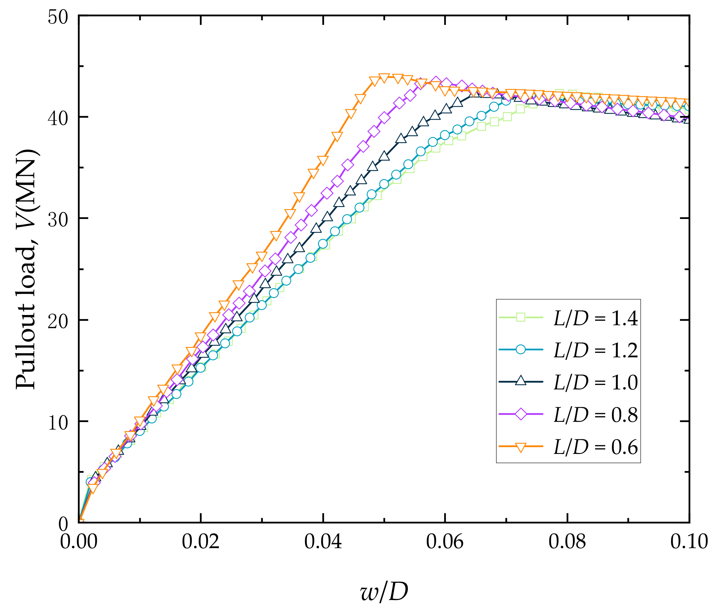
A smaller L/D ratio leads to a larger peak pullout load and higher initial stiffness. There is a 4.4% increase in peak pullout load in sand and a 29.6% increase in peak pullout load in soft clay when the L/D ratio decreases from 1.4 to 0.6. The soil failure displacement at the time of reaching the peak pullout load decreases with a reduction in L/D.
(3)
During the initial stage of pullout, the suction bucket foundation experiences upward-directed frictional resistance, with the highest amount of frictional resistance located at the foundation’s base. As the foundation moves upward, the frictional resistance on the outer wall of the bucket gradually changes from upward to downward. This change is observed more quickly in the lower part of the foundation. During the pullout process of 0.01D~0.02D, there is a situation where the upper frictional resistance on the bucket foundation is upward and the lower frictional resistance is downward.
(4)
During the process of removing the suction bucket, the suction pressure gradually increases until the soil fails. The suction force at the lower part of the bucket lid is one of the main factors affecting its pullout resistance. At L/D = 1.4, the suction force accounts for 38.3% of the peak pullout load, and this proportion increases as L/D decreases. At L/D = 0.6, the suction force constitutes more than 50% of the peak pullout load.
(5)
The displacement of soil failure at the ultimate pullout load exhibits a lagging trend compared to the displacement when the frictional resistance of the bucket wall begins to stabilize. This lag is due to the sustained increase in suction even as the frictional resistance stabilizes.

Author Contributions

Conceptualization, P.C.; methodology, R.Z.; software, P.C.; validation, H.L., P.C. and Y.C.; writing—original draft preparation, P.C., Y.C. and Z.L.; writing—review and editing, H.L. and R.Z.; visualization, Y.C. and Z.L.; supervision, H.L.; project administration, P.C.; funding acquisition, R.Z. All authors have read and agreed to the published version of the manuscript.

Funding

This research was funded by the Special Fund Project for the Development of Marine Economy in Guangdong Province (Six Major Marine Industries) (Grant No. GDNRC [2022]24) and the Key-Area and Development Program of Guangdong Province (Grant No. 2021B0707030001).

Institutional Review Board Statement

Not applicable.

Informed Consent Statement

Not applicable.

Data Availability Statement

The data presented in this study are available upon request.

Conflicts of Interest

The authors declare no conflicts of interest.

References

  1. Global Wind Energy Council. GWECs Global Offshore Wind Report 2022. Available online: https://gwec.net/gwecs-global-offshore-wind-report/ (accessed on 5 January 2024).
  2. Byrne, B.W.; Houlsby, G.T. Foundations for offshore wind turbines. Philos. Trans. R. Soc. Lond. Ser. A Math. Phys. Eng. Sci. 2003, 361, 2909–2930. [Google Scholar] [CrossRef]
  3. Xiaochun, S.; Riqing, X.; Xiaonan, G.; Guoxiang, C.; Zhongli, Y. Development of bucket foundation. China Civ. Eng. J. 2000, 33, 68–92. [Google Scholar] [CrossRef]
  4. Feld, T.; Rasmussen, J.L.; Sørensen, P.H. Structural and Economic Optimization of Offshore Wind Turbine Support Structure and Foundation In AAU Geotechnical Engineering Papers: Foundation Engineering Paper; Geotechnical Engineering Group: Aalborg, Denmark, 1999; Volume R 9904. [Google Scholar]
  5. Wang, Y.; Zhu, X.; Lv, Y.; Yang, Q. Large deformation finite element analysis of the installation of suction caisson in clay. Mar. Georesources Geotechnol. 2018, 36, 883–894. [Google Scholar] [CrossRef]
  6. Shen, K.; Guo, Z.; Wang, L.; Rui, S.; He, B. Investigation on seepage erosion and safety mechanism of suction caisson installation. In Proceedings of the 1st Vietnam Symposium on Advances in Offshore Engineering: Energy and Geotechnics; Springer: Singapore, 2018. [Google Scholar] [CrossRef]
  7. Guo, W.; Chu, J.; Kou, H. Model tests of soil heave plug formation in suction caisson. Proc. Inst. Civ. Eng. Geotech. Eng. 2016, 169, 214–223. [Google Scholar] [CrossRef]
  8. Byrne, B.W.; Houlsby, G.T. Assessing novel foundation options for offshore wind turbines. In Proceedings of the World Maritime Technology Conference, London, UK, 6–10 March 2016. [Google Scholar]
  9. Byrne, B.; Houlsby, G.; Martin, C.; Fish, P. Suction caisson foundations for offshore wind turbines. Wind Eng. 2002, 26, 145–155. [Google Scholar] [CrossRef]
  10. Houlsby, G.T.; Kelly, R.B.; Huxtable, J.; Byrne, B.W. Field trials of suction caissons in clay for offshore wind turbine foundations. Géotechnique 2005, 55, 287–296. [Google Scholar] [CrossRef]
  11. Houlsby, G.T.; Ibsen, L.B.; Byrne, B.W. Suction caissons for wind turbines In Frontiers in Offshore Geotechnics: ISFOG; CRC Press: Boca Raton, FL, USA, 2005; pp. 75–93. [Google Scholar]
  12. Kim, D.J.; Choo, Y.W.; Kim, J.H.; Kim, S.; Kim, D.S. Investigation of monotonic and cyclic behavior of tripod suction bucket foundations for offshore wind towers using centrifuge modeling. J. Geotech. Geoenviron. Eng. 2014, 140, 04014008. [Google Scholar] [CrossRef]
  13. Hung, L.C.; Lee, S.; Tran, N.X.; Kim, S.R. Experimental investigation of the vertical pullout cyclic response of bucket foundations in sand. Appl. Ocean Res. 2017, 68, 325–335. [Google Scholar] [CrossRef]
  14. Hong, S.; Vicent, S.; Gu, K.Y.; Kim, S.R. Effect of drainage condition on the pullout characteristics of bucket foundations in sand. Ocean Eng. 2022, 260, 111994. [Google Scholar] [CrossRef]
  15. Vicent, S.; Kim, S.R.; Bong, T. Effect of loading rate on the pullout capacity of offshore bucket foundations in sand. Ocean Eng. 2020, 210, 107427. [Google Scholar] [CrossRef]
  16. Ssenyondo, V.; Hong, S.; Bong, T.; Kim, S.R. Effects of embedment depth on the pullout capacity of bucket foundations in sand. Ocean Eng. 2021, 237, 109643. [Google Scholar] [CrossRef]
  17. Zhang, Y.; Wang, M.; Lou, Z. A study on the mechanism of interaction between bucket foundation and soil under vertical loadings. China Civ. Eng. J. 2005, 38, 97–101. [Google Scholar]
  18. Sun, X.; Luan, M.; Tang, X. Study of horizontal bearing capacity of bucket foundation on saturated soft clay ground. Rock Soil Mech. 2010, 31, 667–672. [Google Scholar] [CrossRef]
  19. Shen, K.; Zhang, Y.; Klinkvort, R.T.; Sturm, H.; Jostad, H.P.; Sivasithamparam, N.; Gou, Z. Numerical simulation of suction bucket under vertical tension loading. In Proceedings of the 8th International Conference on Offshore Site Investigation and Geotechnics, London, UK, 12–14 September 2017. [Google Scholar]
  20. Asakereh, A.; Kamali, A.H. Evaluation of Influencing Factors on the Pull-out Behavior of Suction Caissons. J. Struct. Eng. Geo-Tech. 2018, 8, 11–18. [Google Scholar]
  21. Dai, J.L. Centrifugal and Numerical Study on Uplift Behaviour of Suction Caissons in Soft Clay; Zhejiang University: Hangzhou, China, 2020. [Google Scholar] [CrossRef]
  22. Kim, S.R.; Oh, M. Group effect on bearing capacities of tripod bucket foundations in undrained clay. Ocean Eng. 2014, 79, 1–9. [Google Scholar] [CrossRef]
  23. Senders, M. Suction Caissons in Sand as Tripod Foundations for Offshore Wind Turbines; University of Western Australia: Perth, Australia, 2009. [Google Scholar] [CrossRef]
  24. Vaitkunaite, E.; Nielsen, B.N.; Ibsen, L.B. Bucket foundation response under various displacement rates. Int. J. Offshore Polar Eng. 2016, 26, 116–124. [Google Scholar] [CrossRef]
  25. Kulczykowski, M. Experimental investigation of skirted foundation in sand subjected to rapid uplift. Arch. Hydro-Eng. Environ. Mech. 2020, 67, 17–34. [Google Scholar] [CrossRef]
  26. Liu, B.; Zhang, Y.; Ma, Z.; Andersen, K.H.; Jostad, H.P. Design considerations of suction caisson foundations for offshore wind turbines in Southern China. Appl. Ocean Res. 2020, 104, 102358. [Google Scholar] [CrossRef]
  27. Puyang, Z.; Lianshuo, X.; Conghuan, L. Pull-Up Resistance Characteristics of Three-Bucket Jacket Foundation in Clay. Adv. New Renew. Energy 2023, 11, 506–511. [Google Scholar]
  28. Iskander, M.; El-Gharbawy, S.; Olson, R. Performance of suction caissons in sand and clay. Can. Geotech. J. 2002, 39, 576–584. [Google Scholar] [CrossRef]
  29. Nabipour, M.; Matin, N.H. An investigation into the pull-out failure mechanisms of suction caissons. Int. J. Marit. Technol. 2015, 4, 21–35. Available online: http://ijmt.ir/article-1-327-en.html (accessed on 11 January 2024).
Figure 1. Application cases of suction bucket jacket foundations in Chinese offshore wind farms.
Jmse 12 00419 g001
Figure 2. Finite element model for analyzing the pullout capacity characteristics of a suction bucket foundation. (a) Prototype bucket for the suction bucket foundation. (b) Finite element model using PLAXIS.
Jmse 12 00419 g002
Figure 3. Comparison of results from physical model tests and finite element simulations.
Jmse 12 00419 g003
Figure 4. The pullout load–displacement curves of suction bucket foundations in sand for different L/D ratios.
Jmse 12 00419 g004
Figure 5. The pullout load–displacement curves of the bucket for different L/D ratios in soft clay.
Jmse 12 00419 g005
Figure 6. Distribution of frictional resistance on the outer wall of the bucket foundation at different L/D ratios in sandy soil. (a) L/D = 1.4; (b) L/D = 1.2; (c) L/D = 1.0; (d) L/D = 0.8; (e) L/D = 0.6.
Jmse 12 00419 g006
Figure 7. Distribution of frictional resistance on the outer wall of the bucket foundation at different L/D ratios in soft clay. (a) L/D = 1.4; (b) L/D = 1.2; (c) L/D = 1.0; (d) L/D = 0.8; (e) L/D = 0.6.
Jmse 12 00419 g007
Figure 8. The variation in pore water pressure at the bottom of the bucket lid in soft clay under different L/D ratios.
Jmse 12 00419 g008
Figure 9. Comparison of peak pullout loads and corresponding suction forces for suction bucket foundations under different L/D ratios during soil failure.
Jmse 12 00419 g009
Table 1. Dimensional values of suction bucket foundations.
Bucket Parameters12345
Skirt length, L (m)16.7515.0013.5011.809.75
Diameter, D (m)11.4512.5013.514.7516.25
Side wall thickness, t1 (mm)5050505050
Head wall thickness, t2 (mm)500500500500500
Aspect ratio, L/D1.41.21.00.80.6
Table 2. Main parameters of the sand material.
Sand Material ParametersValue
Saturated unit weight, γsat (kN/m3)20
Poisson’s ratio, v0.35
Initial elastic modulus, E (kPa)1000
Stiffness increment, Einc (kPa/m)1000
Initial undrained shear strength, Su (kPa)1
Strength increment, Su,inc (kPa/m)4
Table 3. Main parameters of the soft clay material.
Clay Material ParametersValue
Natural unit weight, γunsat (kN/m3)16
Saturated unit weight, γsat (kN/m3)17
Shear modulus in drained triaxial test, E50ref (kPa)2000
Shear modulus in consolidation test, Eoedref (kPa)2000
Unload/Reload modulus, Eurref (kPa)10,000
Unload Poisson’s ratio, v0.2
Stress exponent, m0.5
Cohesion, c′ (kPa)5
Friction angle, φ′ (°)25
Dilatancy angle, Ψ′ (°)0
Overconsolidation ratio, OCR1.5
Preconsolidation stress, POP1
Permeability, k (m/s)6.944 × 10−6
Table 4. The maximum pullout load and soil failure displacement of suction bucket foundations in sand for various L/D ratios.
Maximum Pullout Load, V (MN)Failure Displacement, w/D
Foundation 1 (L/D = 1.4)42.0790.078
Foundation 2 (L/D = 1.2)42.1640.072
Foundation 3 (L/D = 1.0)42.2610.064
Foundation 4 (L/D = 0.8)43.4460.057
Foundation 5 (L/D = 0.6)43.9550.049
Table 5. Maximum pullout loads and soil failure displacements of the bucket for different L/D ratios in soft clay.
Maximum Pullout Load, V (MN)Failure Displacement, w/D
Foundation 1 (L/D = 1.4)68.8830.047
Foundation 2 (L/D = 1.2)74.1220.045
Foundation 3 (L/D = 1.0)74.3340.041
Foundation 4 (L/D = 0.8)78.9440.037
Foundation 5 (L/D = 0.6)89.2660.033
Table 6. Pullout displacement when frictional resistance on the outer wall of the bucket tends to stabilize.
Displacement, w/D
Foundation 1 (L/D = 1.4)0.024
Foundation 2 (L/D = 1.2)0.022
Foundation 3 (L/D = 1.0)0.019
Foundation 4 (L/D = 0.8)0.018
Foundation 5 (L/D = 0.6)0.017
Table 7. The vertical displacement and suction pressure of the bucket corresponding to the tensile failure of the soil.
Displacement, w/DSuction Pressure (kPa)
Foundation 1 (L/D = 1.4)0.047−240.22
Foundation 2 (L/D = 1.2)0.045−247.88
Foundation 3 (L/D = 1.0)0.041−248.50
Foundation 4 (L/D = 0.8)0.037−242.67
Foundation 5 (L/D = 0.6)0.033−227.59
Disclaimer/Publisher’s Note: The statements, opinions and data contained in all publications are solely those of the individual author(s) and contributor(s) and not of MDPI and/or the editor(s). MDPI and/or the editor(s) disclaim responsibility for any injury to people or property resulting from any ideas, methods, instructions or products referred to in the content.

