
Failure Behavior of Corrugated Pressure Cylindrical Shells with Variable Wall Thickness under Uniform External Pressure

Abstract
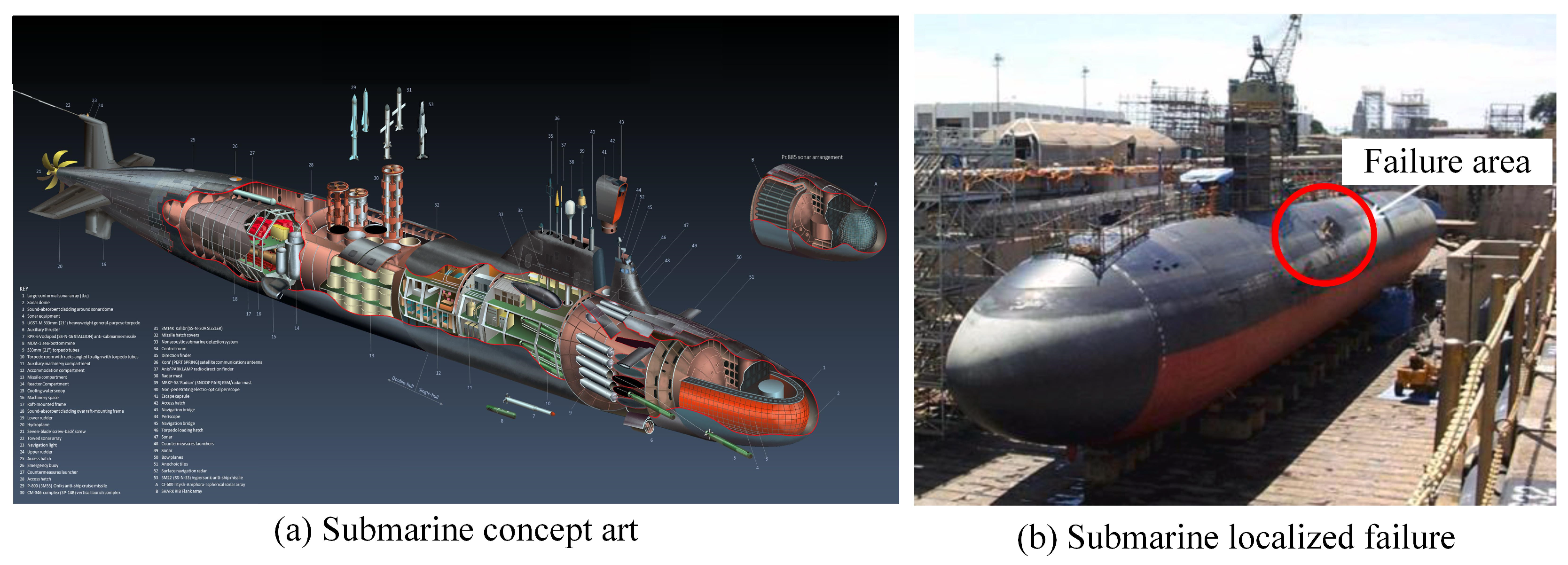
1. Introduction
2. Specimen Design and Measurement Methods
2.1. Specimen Design
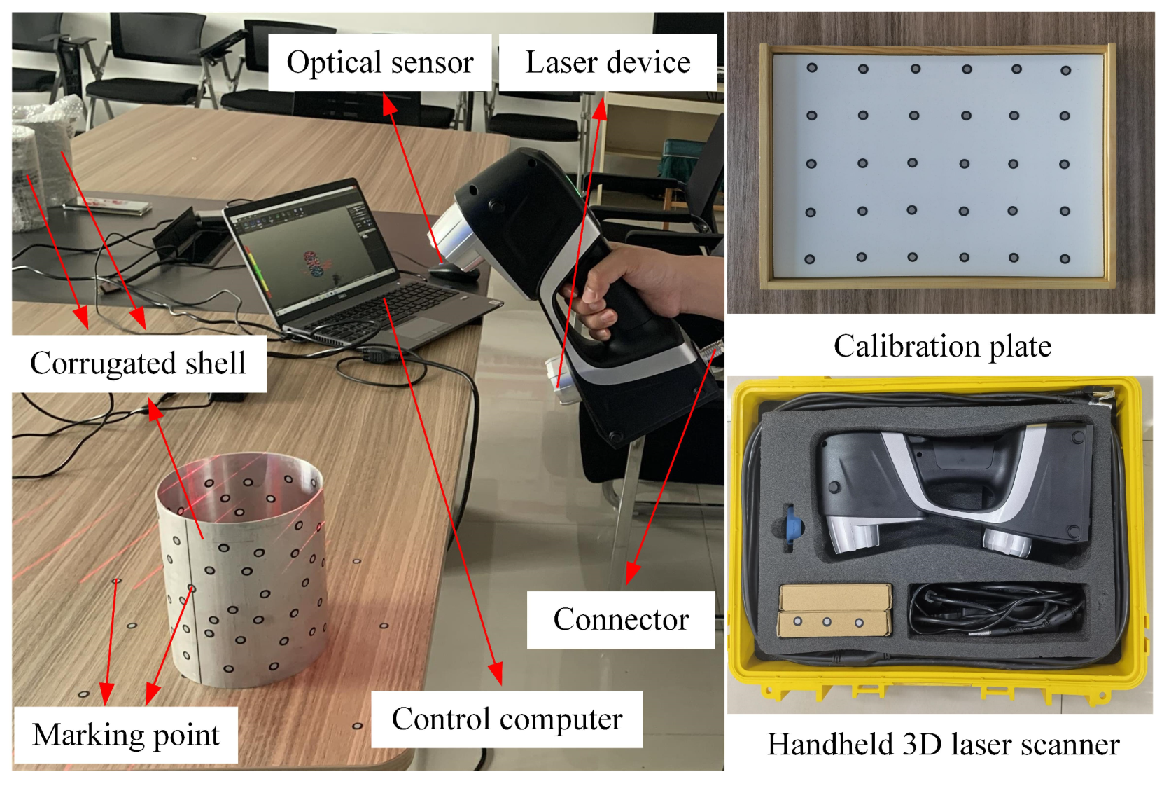
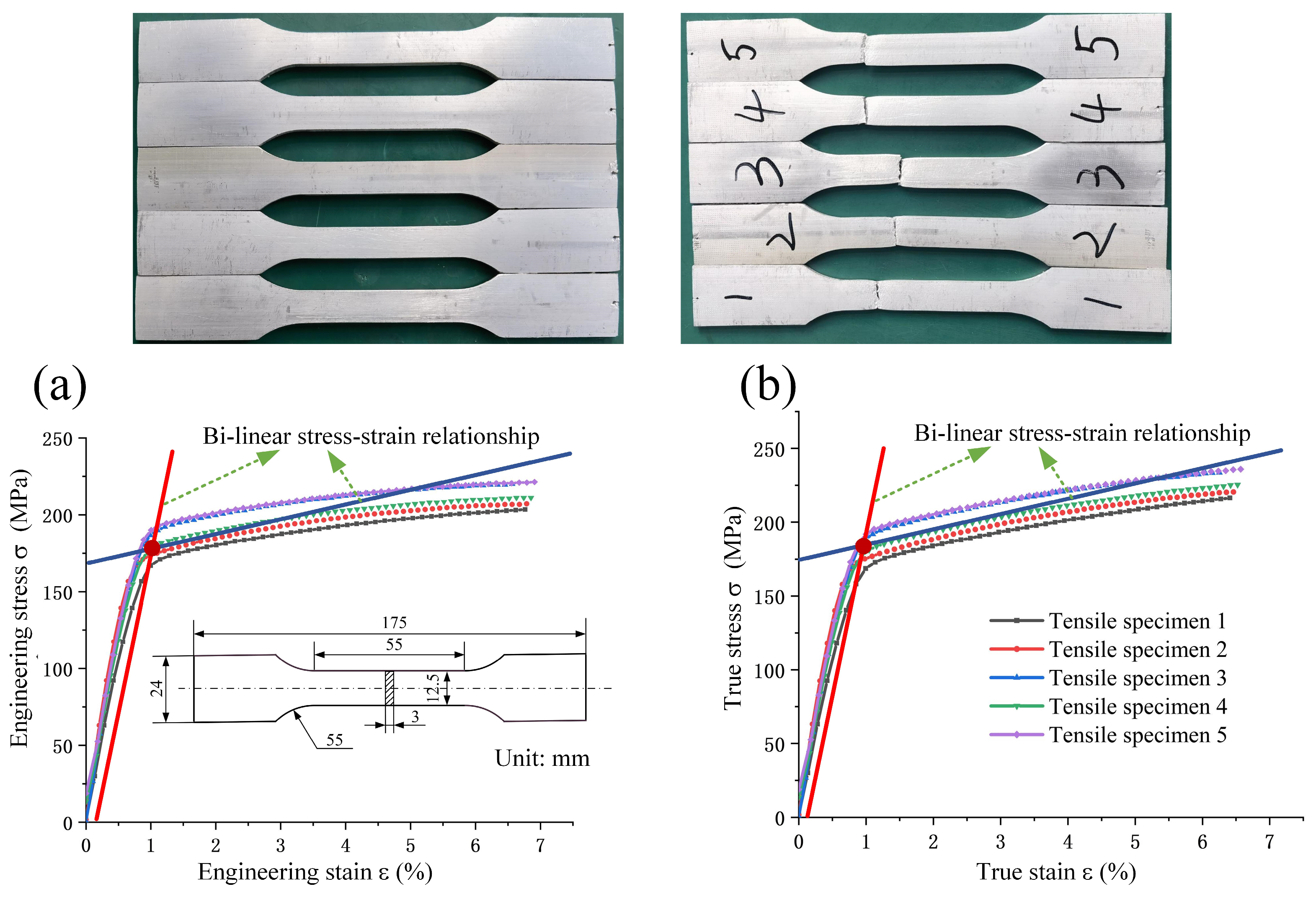
2.2. Geometric Parameter Measurements
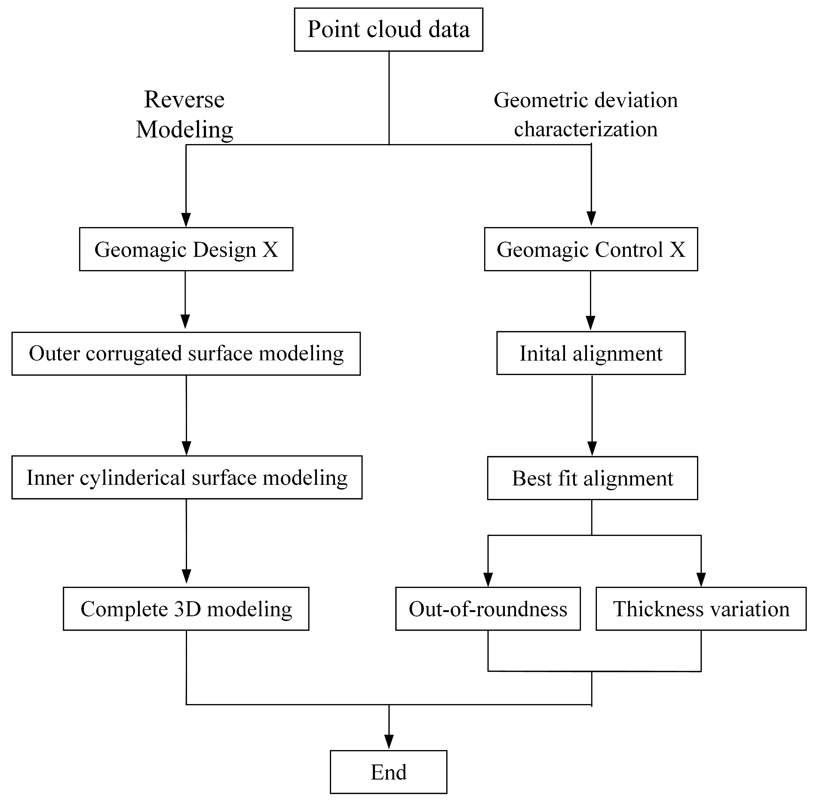
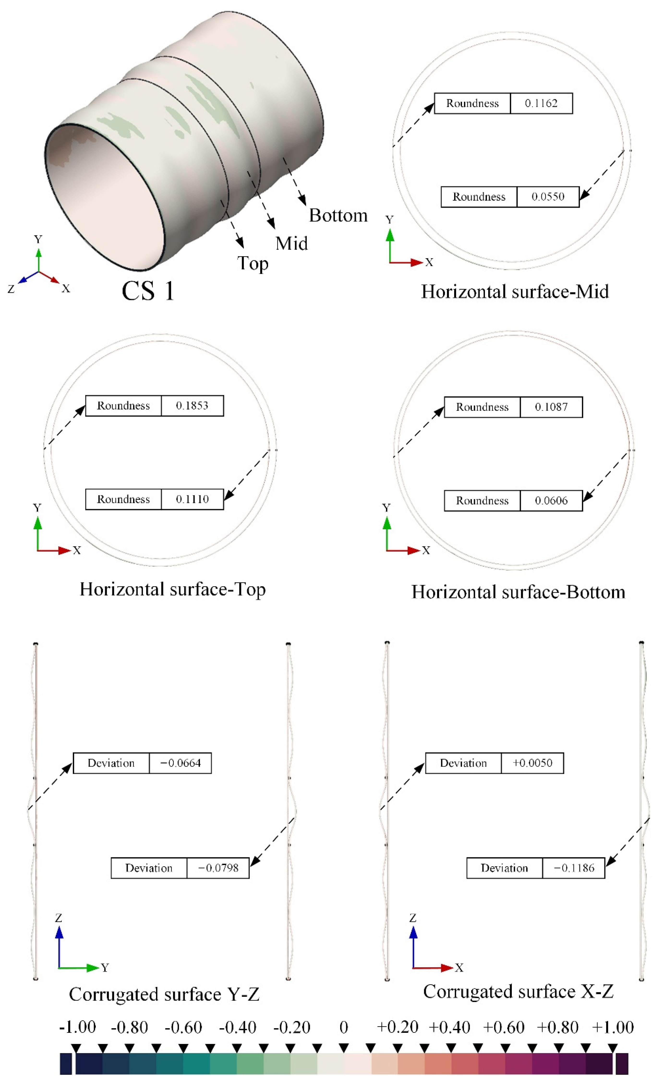
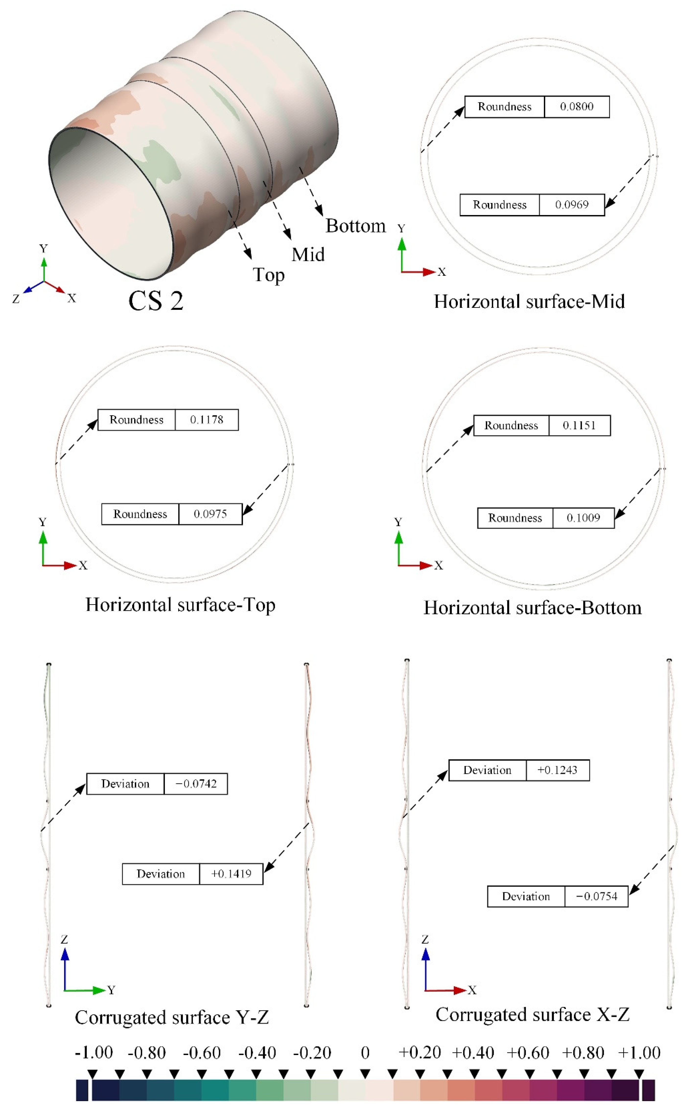
2.3. Reverse Modeling and Geometric Imperfections Characterization
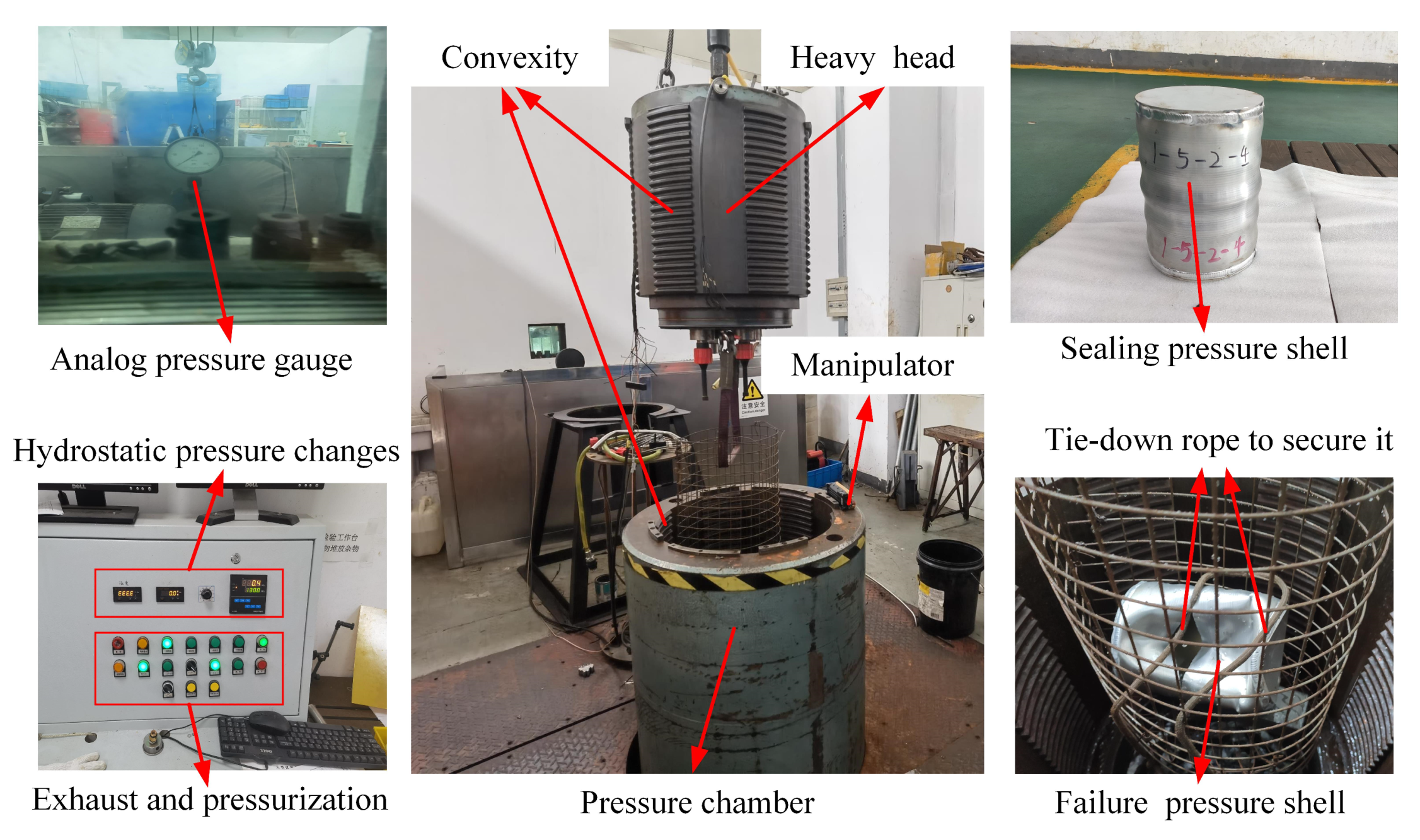
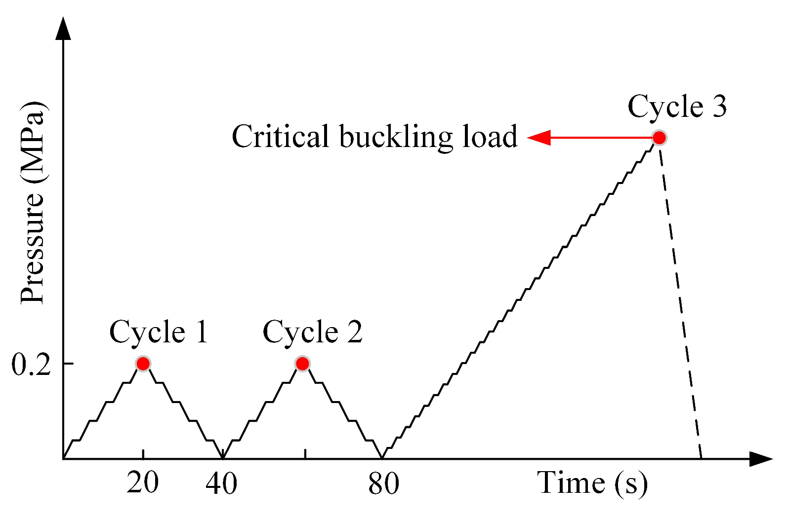
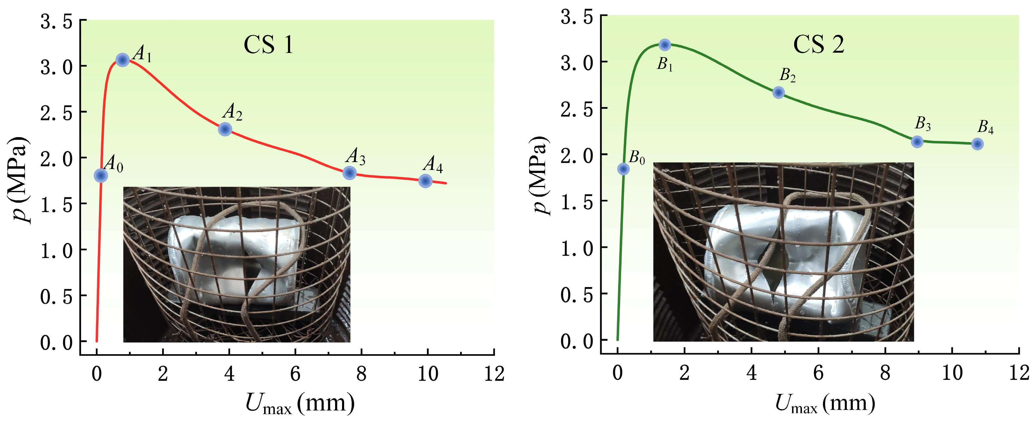
3. Hydrostatic Uniform External Pressure Test
4. Nonlinear Buckling Failure Analysis
4.1. Solver Selection
4.2. Mesh Selection
4.3. Results Analysis and Discussion
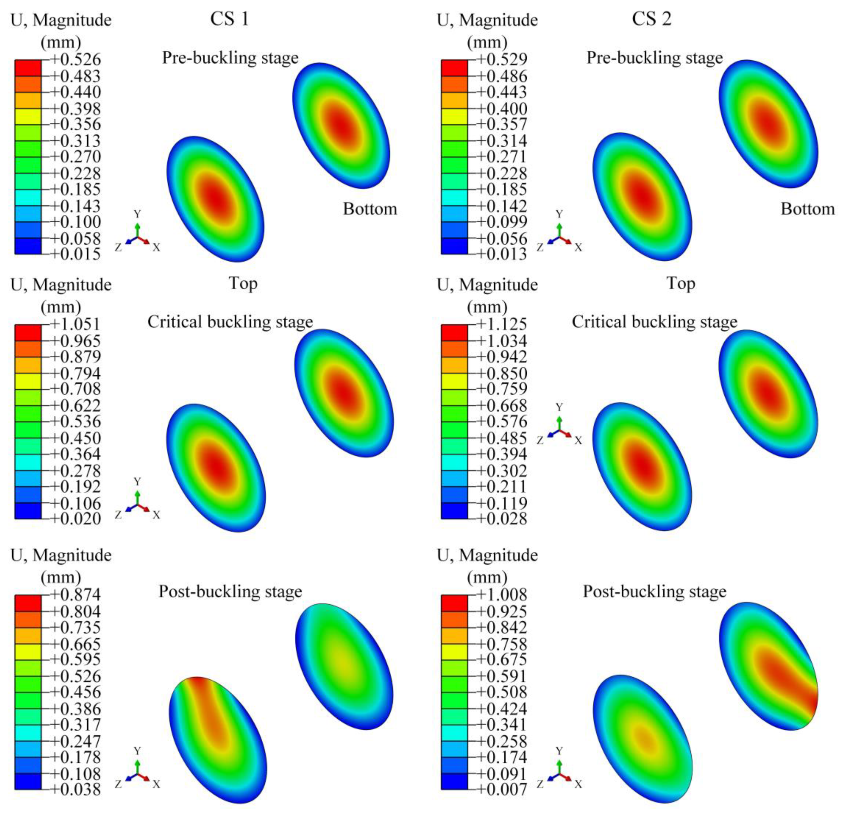
4.3.1. Sealing Circular Plates Variations
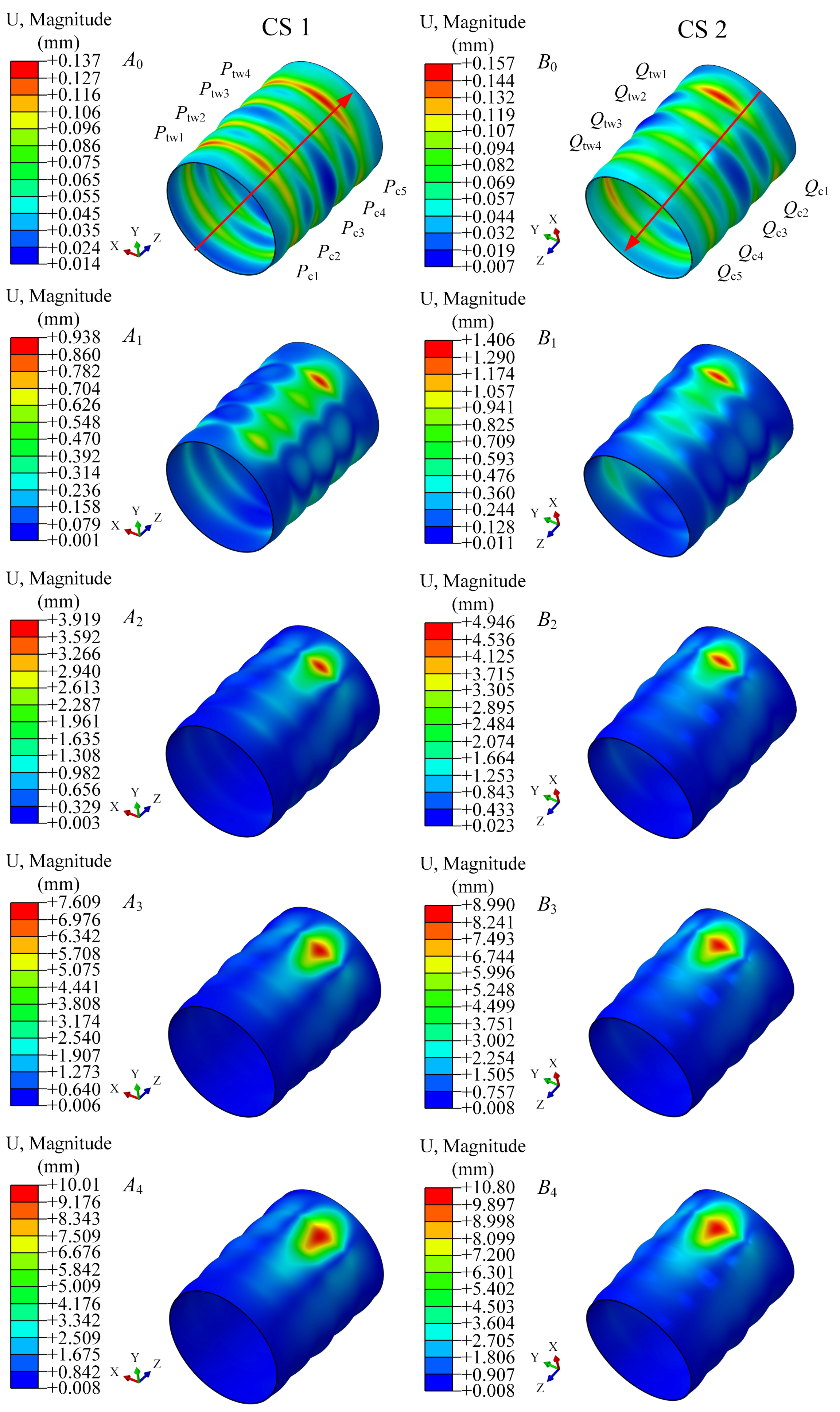
4.3.2. Corrugated Shell Variations
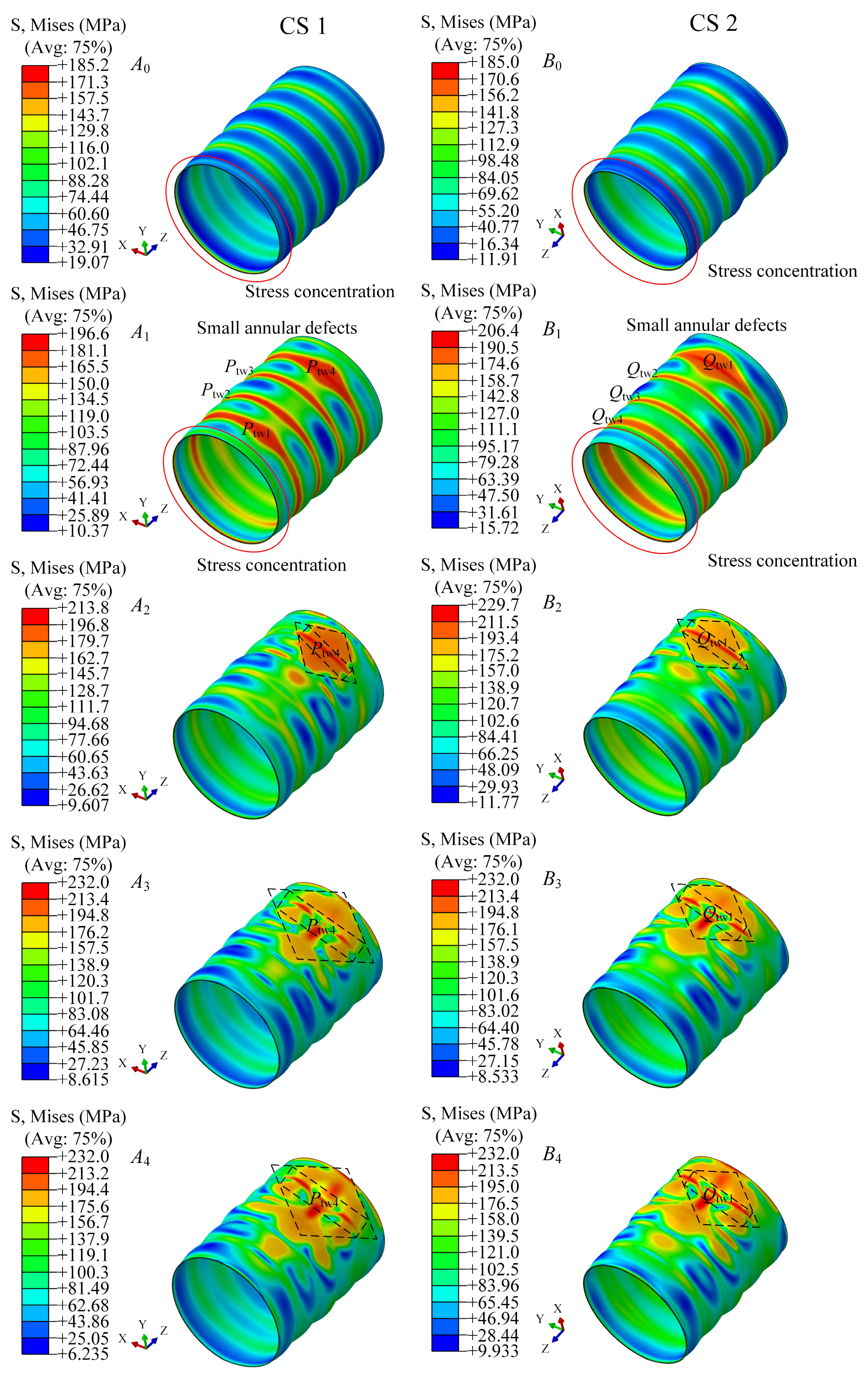
4.3.3. Surface Defect Generation
5. Discussion
6. Conclusions
- (1)
- The hydrostatic pressure test results show that the critical buckling load of the two corrugated pressure cylindrical shells differed by only 0.2 MPa. The reproducibility and reasonableness of the test results are proved.
- (2)
- The numerical simulation results for the critical buckling load of the corrugated pressure cylindrical shell considering fabrication imperfections were in good agreement with the test results. It is demonstrated that the reverse modeling technique has great potential in reproducing the shell failure behavior.
- (3)
- The corrugated shell equilibrium path exhibits a regular variation that is a typical steady-state buckling. The corrugated structure provides an additional advantage in retarding the generation and expansion of defects on the shell surface.
Author Contributions
Funding
Institutional Review Board Statement
Informed Consent Statement
Data Availability Statement
Conflicts of Interest
References
- Stefan, S.; Baljit, S.; John, W. Submarine Hull Impacts: Validation of Finite Element Models from Submarine Impact Trials; Rolls-Royce and the UK MoD: London, UK, 2009. [Google Scholar]
- Donner, R.; Besnier, F.; Le, S.H. Numerical simulation of ship-submarine collisons. In Proceedings of the Practical Design of Ships and Other Floating Structure Conference, PRADS, Shanghai, China, 16–21 September 2001. [Google Scholar]
- Wikipedia. ARA San Juan (S-42), the Free Encyclopedia. 2019. Available online: https://en.wikipedia.org/wiki/ARASanJuan(S-42) (accessed on 2 August 2019).
- Geoffrey, P.C. The Design of an Intelligent Decision Support Tool for Submarine Commanders. Master’s Thesis, Engineering Systems at the Massachusetts Institute of Technology, Cambridge, MA, USA, 2009. [Google Scholar]
- Burcher, R.; Rydill, L. Concepts in Submarine Design, 1st ed.; Cambridge University Press: Cambridge, MA, USA, 1995. [Google Scholar]
- DPA. SSP 74 Design of Submarine Structures; Defence Procurement Agency, Sea Technology Group: London, UK, 2001. [Google Scholar]
- Wikipedia. The Manhattan Project, the Free Encyclopedia. 2019. Available online: https://en.wikipedia.org/wiki/Manhattan_Project (accessed on 1 August 2019).
- MacKay, J.R.; Smith, M.J.; Keulen, F.V.; Bosman, T.N.; Pegg, N.G. Experimental investigation of the strength and stability of submarine pressure hulls with and without artificial corrosion damage. Mar. Struct. 2010, 23, 339–359. [Google Scholar] [CrossRef]
- MacKay, J.R.; Keulen, F.V. Partial safety factor approach to the design of submarine pressure hulls using nonlinear finite element analysis. Finite Elem. Anal. Des. 2013, 65, 1–16. [Google Scholar] [CrossRef]
- Smith, M.J.; Macadam, T.; MacKay, J.R. Integrated modelling, design and analysis of submarine structures. Ships Offshore Struct. 2015, 10, 349–366. [Google Scholar] [CrossRef]
- Yu, C.L.; Guo, Q.B.; Gong, X.B.; Yang, Y.F.; Zhang, J. Fatigue life assessment of pressure hull of deep-sea submergence vehicle. Ocean Eng. 2022, 245, 110528. [Google Scholar] [CrossRef]
- Wen, G.L.; Lu, Y.Z.; Zhang, Z.Y.; Ma, C.S.; Yin, H.F.; Cui, Z. Line spectra reduction and vibration isolation via modified projective synchronization for acoustic stealth of submarines. J. Sound Vib. 2009, 324, 954–961. [Google Scholar] [CrossRef]
- Jeong, S.J.; Hong, S.Y.; Song, J.H.; Kwon, H.W.; Seol, H.S. Numerical method to determine the cavitation inception speed of a submarine propeller based on the noise obtained from bubble dynamics. Ocean Eng. 2022, 245, 110464. [Google Scholar] [CrossRef]
- Chen, F.; Chen, Y.; Hua, H.X. Vibration analysis of a submarine elastic propeller-shaft-hull system using FRF-based substructuring method. J. Sound Vib. 2019, 443, 460–482. [Google Scholar] [CrossRef]
- Han, H.; Jeon, S.; Kim, Y.; Lee, C.; Lee, D.; Lee, G.; Lee, S. Monitoring of the cavitation inception speed and sound pressure level of the model propeller using accelerometer attached to the model ship in the cavitation tunnel. Ocean Eng. 2022, 266, 112906. [Google Scholar] [CrossRef]
- Yu, K.; Park, D.; Choi, J.; Seol, H.; Park, I.; Lee, S.G. Effect of skew on the tonal noise characteristics of a full-scale submarine propeller. Ocean Eng. 2023, 276, 114218. [Google Scholar] [CrossRef]
- Sarigiguzel, F.; Kilavuz, A.; Ozgoren, M.; Durhasan, T.; Sahin, B.; Kavurmacioglu, L.A.; Akilli, H.; Sekeroglu, E.; Yaniktepe, B. Experimental investigation of free-surface effects on flow characteristics of a torpedo-like geometry having a cambered nose. Ocean Eng. 2022, 253, 111174. [Google Scholar] [CrossRef]
- Bridges, D.H.; Blanton, J.N.; Brewer, W.H.; Park, J.T. Experimental investigation of the flow past a submarine at angle of drift. AIAA J. 2003, 41, 71–81. [Google Scholar] [CrossRef]
- Palomba, G.; Corigliano, P.; Crupi, V.; Epasto, G.; Guglielmino, E. Static and Fatigue Full-Scale Tests on a Lightweight Ship Balcony Overhang with Al/Fe Structural Transition Joints. J. Mar. Sci. Eng. 2022, 10, 1382. [Google Scholar] [CrossRef]
- Ekmekci, A.; Rockwell, D. Effects of a geometrical surface disturbance on flow past a circular cylinder: A large-scale spanwise wire. J. Fluid Mech. 2010, 665, 120–157. [Google Scholar] [CrossRef]
- Gao, T.; Wang, Y.; Pang, Y.; Cao, J. Hull shape optimization for autonomous underwater vehicles using CFD. Eng. Appl. Comput. Fluid Mech. 2016, 10, 599–607. [Google Scholar] [CrossRef]
- Myring, D.F. A theoretical study of body drag in subcritical axisymmetric flow. Aeronaut. Q. 1976, 27, 186–194. [Google Scholar] [CrossRef]
- Tian, W.L.; Song, B.W.; Ding, H. Numerical research on the influence of surface waves on the hydrodynamic performance of an AUV. Ocean Eng. 2019, 183, 40–56. [Google Scholar] [CrossRef]
- Wu, H.Y.; Niu, W.D.; Wang, S.X.; Yan, S.Z. A feedback control strategy for improving the motion accuracy of underwater gliders in currents: Performance analysis and parameter optimization. Ocean Eng. 2022, 252, 111250. [Google Scholar] [CrossRef]
- Wang, G.H.; Yang, Y.A.; Wang, S.X. Ocean thermal energy application technologies for unmanned underwater vehicles: A comprehensive review. Appl. Energy 2020, 278, 115752. [Google Scholar] [CrossRef]
- Moustabchir, H.; Azari, Z.; Hariri, S.; Dmytrakh, I. Experimental and numerical study of stress–strain state of pressurised cylindrical shells with external defects. Eng. Fail. Anal. 2010, 17, 506–514. [Google Scholar] [CrossRef]
- Ismail, M.S.; Purbolaksono, J.; Andriyana, A.; Tan, C.J.; Muhammad, N.; Liew, H.L. The use of initial imperfection approach in design process and buckling failure evaluation of axially compressed composite cylindrical shells. Eng. Fail. Anal. 2015, 51, 20–28. [Google Scholar] [CrossRef]
- Mehretehran, A.M.; Maleki, S. Axial buckling of imperfect cylindrical steel silos with isotropic walls under stored solids loads: FE analyses versus Eurocode provisions. Eng. Fail. Anal. 2022, 137, 106282. [Google Scholar] [CrossRef]
- Jo, B.; Kasahara, N.; Okamoto, K. Buckling of cylindrical stainless-steel tubes subjected to external pressure at extremely high temperatures. Eng. Fail. Anal. 2018, 92, 61–70. [Google Scholar] [CrossRef]
- Christensen, C.F.; Wang, F.W.; Sigmund, O. Topology optimization of multiscale structures considering local and global buckling response. Comput. Methods Appl. Mech. Eng. 2023, 408, 115969. [Google Scholar] [CrossRef]
- Viswanath, A.; Khalil, M.; Maskari, F.A.; Cantwell, W.J.; Khan, K.A. Harnessing buckling response to design lattice structures with improved buckling strength. Mater. Des. 2023, 232, 112113. [Google Scholar] [CrossRef]
- Gannon, L. Submerged aluminum cylinder response to close-proximity underwater explosions—A comparison of experiment and simulation. Int. J. Impact Eng. 2019, 133, 103339. [Google Scholar] [CrossRef]
- Cho, S.R.; Muttaqie, T.; Do, Q.T.; So, H.Y.; Sohn, J.M. Ultimate strength formulation considering failure mode interactions of ring-stiffened cylinders subjected to hydrostatic pressure. Ocean Eng. 2018, 161, 242–256. [Google Scholar] [CrossRef]
- Barlag, S.; Rothert, H. An idealization concept for the stability analysis of ring reinforced cylindrical shells under external pressure. Int. J. Non-Linear Mech. 2002, 37, 745–756. [Google Scholar] [CrossRef]
- Tian, K.; Wang, B.; Hao, P.; Waas, A.M. A high-fidelity approximate model for determining lower-bound buckling loads for stiffened shells. Int. J. Solids Struct. 2018, 148–149, 14–23. [Google Scholar] [CrossRef]
- Do, Q.T.; Muttaqie, T.; Nhut, P.T.; Vu, M.T.; Khoa, N.D.; Prabowo, A.R. Residual ultimate strength assessment of submarine pressure hull under dynamic ship collision. Ocean Eng. 2022, 266, 112951. [Google Scholar] [CrossRef]
- Viljoen, H.C.; Mahomed, N.; Cupido, L.H.; Mitchell, G.P. Effect of corrosion thinning on depth of operation: Case study of an HY-80 steel submarine pressure hull. Mar. Struct. 2022, 81, 103103. [Google Scholar] [CrossRef]
- Ma, X.T.; Hao, P.; Wu, H.; Wang, B.; Bi, X.J.; Du, K.F.; Ke, X.G. High-fidelity numerical simulation and experimental validation of a 1600-mm-diameter axial loaded grid stiffened cylindrical shell. Int. J. Solids Struct. 2023, 273, 112262. [Google Scholar] [CrossRef]
- Shen, K.C.; Yang, Z.Q.; Jiang, L.L.; Pan, G. Buckling and post-buckling behavior of perfect/perforated composite cylindrical shells under hydrostatic pressure. J. Mar. Sci. Eng. 2022, 10, 278. [Google Scholar] [CrossRef]
- Li, Z.; Pasternak, H.; Andreas, J. A Buckling of ring-stiffened cylindrical shell under axial compression: Experiment and numerical simulation. Thin-Walled Struct. 2021, 164, 107888. [Google Scholar] [CrossRef]
- Lee, S.K.; Jones, M.B.; Quick, H. Loads and hull-pressure measurements on a generic submarine in different stages of model build-up. Ocean Eng. 2023, 271, 113677. [Google Scholar] [CrossRef]
- Chmelko, V.; Biro, D. Safety of pressure pipe operation with corrosive defect. Procedia Struct. Integr. 2019, 17, 520–525. [Google Scholar] [CrossRef]
- Chmelko, V.; Šulko, M.; Garan, M.; Zvirko, O. Influence of additional factors on the integrity of pipelines with small corrosion defects. Procedia Struct. Integr. 2022, 42, 315–320. [Google Scholar] [CrossRef]
- Wei, C.Q.; Chen, G.; Sergeev, A.; Yeh, J.; Chen, J.H.; Wang, J.M.; Ji, S.C.; Wang, J.; Yang, D.H.; Xiang, S.H.; et al. Implosion of the argentinian submarine ARA san Juan S-42 undersea: Modeling and simulation. Commun. Nonlinear Sci. Numer. Simulat. 2020, 91, 105397. [Google Scholar] [CrossRef]
- Cho, S.R.; Muttaqie, T.; Do, Q.T.; Kim, S.; Kim, S.M.; Han, D.H. Experimental investigations on the failure modes of ring-stiffened cylinders under external hydrostatic pressure. Int. J. Nav. Archit. Ocean. Eng. 2018, 10, 711–729. [Google Scholar] [CrossRef]
- Wang, H.K.; Yu, Y.; Yu, J.X.; Duan, J.H.; Zhang, Y.; Li, Z.M.; Wang, C.M. Effect of 3D random pitting defects on the collapse pressure of pipe—Part I: Experiment. Thin-Walled Struct. 2018, 129, 512–526. [Google Scholar] [CrossRef]
- Covert, S. Yasen-M Cruise Missile Submarine. Available online: http://www.hisutton.com (accessed on 4 August 2021).
- Kristina, D.; William, L.B. USS Greenville collides with Japan’s Ehime Maru: Cultural issues in image repair discourse. Publ. Relat. Rev. 2004, 30, 177–185. [Google Scholar] [CrossRef]
- Li, W.X.; Sun, F.F.; Wei, W.Y.; Liu, D.B.; Zhang, X.; Li, M.; Fan, H.L. Fabrication and testing of composite corrugated-core sandwich cylinder. Compos. Sci. Technol. 2018, 156, 127–135. [Google Scholar] [CrossRef]
- Wang, Q.S.; Li, Z.; Qin, B.; Zhong, R.; Zhai, Z.Y. Vibration characteristics of functionally graded corrugated plates by using differential quadrature finite element method. Compos Struct. 2021, 274, 114344. [Google Scholar] [CrossRef]
- Wang, S.; Wang, X.G.; Liu, X.H.; Li, C.S. Experiment and simulation of variable thickness rolling for 3D-profiled blank. J. Mater. Process. Technol. 2021, 290, 116971. [Google Scholar] [CrossRef]
- American Bureau of Shipping (ABS). Rules for Building and Classing Underwater Vehicles; System and Hyperbaric Facilities: Houston, TX, USA, 2012. [Google Scholar]
- China Classification Society (CCS). Submersible Systems and Submersible Classification Specification; China Classification Society: Beijing, China, 2018. [Google Scholar]
- Luo, G.M.; Hsu, Y.C. Nonlinear buckling strength of out-of-roundness pressure hull. Thin-Walled Struct. 2018, 130, 424–434. [Google Scholar] [CrossRef]
- Zhang, X.; Sun, J.L.; Wu, R.Z.; Peng, Y. Buckling performance of inner corrugated pressure shells under external hydrostatic pressure. Ocean Eng. 2023, 288, 115963. [Google Scholar] [CrossRef]
- Schmidová, E.; Klejch, F.; Sunilkumar, M.R. Development of anisotropy and strain hardening in damaged stamped parts made of IF steel. Eng. Fail. Anal. 2023, 145, 107015. [Google Scholar] [CrossRef]
- Ribeiro, V.; Correia, J.; Mourão, A.; Lesiuk, G.; Gonçalves, A.; De, J.A.; Berto, F. Fatigue crack growth modelling by means of the strain energy density-based Huffman model considering the residual stress effect. Eng. Fail. Anal. 2022, 140, 106543. [Google Scholar] [CrossRef]
- Samadi, F.; Mourya, J.; Wheatley, G.; Khan, M.N.; Nejad, R.M.; Branco, R.; Macek, W. An investigation on residual stress and fatigue life assessment of T-shape welded joints. Eng. Fail. Anal. 2022, 141, 106685. [Google Scholar] [CrossRef]
- Zhang, K.; Dai, S.H.; Jiang, B.Y.; Wang, D.H.; Han, C.; Liu, Q.Y. Simulation optimization and experimental research on heat-treatment process for ring remanufacturing of TBM disc cutters. Surf. Coat. Technol. 2023, 475, 130133. [Google Scholar] [CrossRef]
- Alizadeh, M.; Vahdatinejad, F.; Pashangeh, S. Feasibility study of producing Al–5Zn–1 Mg alloy by accumulative roll bonding process and subsequent heat treatment. Eng. Fail. Anal. 2023, 143, 106927. [Google Scholar] [CrossRef]
- Zhang, J.; Wang, M.L.; Wang, W.B.; Tang, W.X.; Zhu, Y.M. Investigation on egg-shaped pressure hulls. Mar. Struct. 2017, 52, 50–66. [Google Scholar] [CrossRef]
- Yang, M.; Yang, S.H.; Wang, Y.H.; Liang, Y.; Wang, S.X.; Zhang, L.H. Optimization design of neutrally buoyant hull for underwater gliders. Ocean Eng. 2020, 209, 107512. [Google Scholar] [CrossRef]
- Pan, B.B.; Cui, W.C.; Shen, Y.S. Experimental verification of the new ultimate strength equation of spherical pressure hulls. Mar. Struct. 2012, 29, 169–176. [Google Scholar] [CrossRef]


| Corrugated Shells | CS1 | CS2 |
|---|---|---|
| Ptest/MPa | 3.2 | 3.4 |
| Pnum/MPa | 3.063 | 3.188 |
| (Ptest − Pnum)/Ptest | 4.28% | 6.24% |
| Nmax | Δlin | Δlmin | Δlmax |
|---|---|---|---|
| 500 | 0.005 | 1e−15 | 0.05 |
| Properties | E (MPa) | μ | σ0 (MPa) | Ks (MPa) |
|---|---|---|---|---|
| Values | 69,900 | 0.33 | 185 | 940,000 |
Disclaimer/Publisher’s Note: The statements, opinions and data contained in all publications are solely those of the individual author(s) and contributor(s) and not of MDPI and/or the editor(s). MDPI and/or the editor(s) disclaim responsibility for any injury to people or property resulting from any ideas, methods, instructions or products referred to in the content. |
© 2024 by the authors. Licensee MDPI, Basel, Switzerland. This article is an open access article distributed under the terms and conditions of the Creative Commons Attribution (CC BY) license (https://creativecommons.org/licenses/by/4.0/).
Share and Cite
Sun, J.; Zhang, X.; Zhang, Y.; Lu, X.; Peng, Y. Failure Behavior of Corrugated Pressure Cylindrical Shells with Variable Wall Thickness under Uniform External Pressure. J. Mar. Sci. Eng. 2024, 12, 385. https://doi.org/10.3390/jmse12030385
Sun J, Zhang X, Zhang Y, Lu X, Peng Y. Failure Behavior of Corrugated Pressure Cylindrical Shells with Variable Wall Thickness under Uniform External Pressure. Journal of Marine Science and Engineering. 2024; 12(3):385. https://doi.org/10.3390/jmse12030385
Chicago/Turabian StyleSun, Jianliang, Xu Zhang, Yuanhe Zhang, Xianghui Lu, and Yan Peng. 2024. "Failure Behavior of Corrugated Pressure Cylindrical Shells with Variable Wall Thickness under Uniform External Pressure" Journal of Marine Science and Engineering 12, no. 3: 385. https://doi.org/10.3390/jmse12030385
APA StyleSun, J., Zhang, X., Zhang, Y., Lu, X., & Peng, Y. (2024). Failure Behavior of Corrugated Pressure Cylindrical Shells with Variable Wall Thickness under Uniform External Pressure. Journal of Marine Science and Engineering, 12(3), 385. https://doi.org/10.3390/jmse12030385