Article

Doppler and Channel Estimation Using Superimposed Linear Frequency Modulation Preamble Signal for Underwater Acoustic Communication

1
College of Information Science and Electronic Engineering, Zhejiang University, Hangzhou 310027, China
2
Interdisciplinary Student Training Platform for Marine Areas, Zhejiang University, Hangzhou 310027, China
3
Zhejiang Provincial Key Laboratory of Information Processing, Communication and Networking, Hangzhou 310027, China
4
Zhoushan Ocean Research Center, Zhejiang University, Zhoushan 316021, China
*
Author to whom correspondence should be addressed.
J. Mar. Sci. Eng. 2024, 12(2), 338; https://doi.org/10.3390/jmse12020338
Submission received: 3 January 2024 / Revised: 2 February 2024 / Accepted: 10 February 2024 / Published: 16 February 2024
(This article belongs to the Topic Advances in Underwater Acoustics and Aeroacoustics)

Abstract

:
Due to the relative motion between transmitters and receivers and the multipath characteristic of wideband underwater acoustic channels, Doppler and channel estimations are of great significance for an underwater acoustic (UWA) communication system. In this paper, a preamble signal based on superimposed linear frequency modulation (LFM) signals is first designed. Based on the designed preamble signal, a real-time Doppler factor estimation algorithm is proposed. The relative correlation peak shift of two LFM signals in the designed preamble signal is utilized to estimate the Doppler factor. Moreover, an enhanced channel estimation algorithm, the correlation-peak-search-based improved orthogonal matching pursuit (CPS-IOMP) algorithm, is also proposed. In the CPS-IOMP algorithm, the excellent autocorrelation characteristic of the designed preamble signal is used to estimate the channel sparsity and multipath delays, which are utilized to construct the simplified dictionary matrix. The simulation and sea trial data analysis results validated the designed preamble, the proposed Doppler estimation algorithm, and the channel estimation algorithm. The performance of the proposed Doppler factor estimation is better than that of the block estimation algorithm. Compared with the original OMP algorithm with known channel sparsity, the proposed CPS-IOMP algorithm achieves a similar estimation accuracy with a smaller computational complexity, as well as requiring no prior knowledge about the channel sparsity.

1. Introduction

Implementing efficient and reliable communication in the underwater acoustic (UWA) channel is a challenging task due to the complex and time-varying characteristics of the UWA channel in terms of the limited bandwidth, strong multipath, serious Doppler effect, and long propagation delay. The Doppler effect in the UWA channel is severe since the sound wave propagating in the water is slow (about 1500 m/s). And Doppler estimation and compensation become a critical issue in the UWA communication system. Moreover, the large multipath delay spread also brings great challenges to UWA communication [1]. Hence, channel estimation and equalization should be used to mitigate the performance degradation resulting from the multipath.
When the UWA communication system with a high data rate is equipped on a mobile underwater node, Doppler estimation and compensation are essential before demodulation at the receiver [2,3]. For the traditional Doppler method, a set of correlators are adopted to compute the correlation between various Doppler replicas of the transmitted signal and the received signal. And then the Doppler shift is determined according to the maximum correlation [4]. Although the resolution of the method can be improved with an increased number of correlators, the computational complexity also significantly increases. To reduce the computational complexity, an efficient block Doppler estimation method was proposed in [5]. In this method, two linear frequency modulation (LFM) signals are respectively inserted before and after the data frame, and the time duration of the data frame can be estimated according to two obtained correlation peaks at the receiver. The time duration change can further be used to estimate the Doppler factor. This method has been widely used in UWA communication because of its efficiency and simplicity. Moreover, several improved methods have been proposed [6,7,8,9,10,11,12]. For example, an adaptive dual-stage Doppler estimation method was proposed in [12]. In the first stage, the block Doppler estimation method was used for a coarse estimation. In the second stage, a bank of fraction-delay Farrow filters was used to correct the Doppler factor. However, these methods need to store the whole data frame, which introduces a large storage overhead and disables the real-time estimation.
A Doppler estimation method based on hyperbolic frequency modulation (HFM) signals, which can obtain real-time estimation, was proposed in [13,14]. In this method, two HFM signals with opposite frequency sweeping directions were inserted before the data frame. At the receiver, two corresponding matched filters were utilized to estimate the Doppler factor. Although the accuracy of this method is independent of the frame length, the estimation accuracy should deteriorate sharply in the presence of a time-varying multipath. To improve the estimation performance in the time-varying multipath environment, a correlation peak matching method was proposed in [15]. However, two HFM signals need to have the same autocorrelation characteristics in this method. And the computational complexity was increased. A new preamble waveform based on an HFM signal was proposed in [16], which leaves a mute span between the up-sweeping HFM and the down-sweeping HFM signals. Apart from using the time-domain property of HFM signals, a speed spectrum estimation method utilizing the spectrum property of the signal was proposed to estimate the Doppler factor in [17].
Recently, numerous achievements in channel estimation for UWA communication have been obtained. According to prior knowledge for the algorithm, the channel estimation methods can be divided into the blind method and the training-sequence-based method. In the blind channel estimation method, the statistical property of received signals is utilized to estimate the channel state information without any prior information of the transmitted signal [18]. The training-sequence-based method performs the channel estimation by utilizing the known training sequence part of the received signals [19]. The training-sequence-based channel estimation method has been widely studied and adopted owing to its low computational complexity and good performance. Moreover, the channel estimation method based on compressed sensing (CS), making full use of the sparsity of the underwater multipath channel, has become a hot research topic [20].
Among the CS-based channel estimation algorithms, orthogonal matching pursuit (OMP) [21] stands out as the most representative with the potential to achieve high estimation accuracy, as well as keeping the computational cost low [20]. However, in the OMP algorithm, determination of the iteration termination condition is a fundamentally challenging problem. Without an appropriate termination condition, not only accuracy but also computational complexity will deteriorate. Considering that the time-varying UWA channel contains both rapidly time-varying and stationary (or slowly varying) components, a sequentially adaptive observation length OMP (SAOL-OMP) algorithm was proposed in [22]. Although the SAOL-OMP algorithm exhibits better performance than the OMP, the iteration termination condition problem was not resolved. To determine the iteration termination condition, an adaptive OMP (A-OMP) algorithm was proposed in [23], where the recovery sparsity was exploited to derive a closed-form expression for the termination condition. However, the A-OMP algorithm has not been validated using sea trial experiments. The sparse-Bayesian-learning-based channel estimation method has been proposed [24,25]. In [24], sparse-Bayesian-learning-framework-based channel estimation methods were investigated, where the convergence error is avoided by utilizing the sparsity of the channel. Meanwhile, better channel estimation performance and lower output bit error rate (BER) were obtained compared to the CS-based method. In [25], a fast channel estimation algorithm based on sparse Bayesian learning using the fast marginal likelihood maximization was proposed. However, although the sparse-Bayesian-learning-based channel estimation method performs well, the computational complexity is much higher, in terms of long computing time and large power consumption.
In this paper, we investigate the Doppler and channel estimation problem for UWA communication using a dedicated preamble signal. In more detail, a preamble signal based on the superimposed LFMs is designed for Doppler and channel estimation. According to the designed preamble signal, we further propose the corresponding Doppler estimation algorithm and channel estimation algorithm. The main contributions of this paper are summarized as follows:
1.
To achieve Doppler and channel estimation using the preamble signal, a preamble signal based on the superimposed LFMs is designed. Specifically, the designed preamble signal is composed of an up-sweeping LFM signal and a down-sweeping LFM signal, which are superimposed in the time domain. Differing from the traditional frame structure that inserts two identical LFM signals before and after the data block, the designed preamble signal can achieve real-time estimation. Compared with the preamble signal using HFM signals, the designed preamble signal is easy to generate and does not increase the time duration.
2.
As revealed in [14], under the influence of the Doppler factor, the LFM signal has an approximate linear relationship between the correlation peak shift and the Doppler factor. Hence, a Doppler estimation method is proposed utilizing the relationship between the relative correlation peak shift of two superimposed LFM signals and the Doppler factor. Moreover, once the Doppler factor is estimated, the timing synchronization can be realized simultaneously.
3.
An improved OMP channel estimation algorithm utilizing the designed preamble signal is proposed. Since the preamble signal is composed of two LFM signals, it also has excellent autocorrelation characteristics. In the proposed algorithm, the received preamble signal (after Doppler compensation) is correlated with the local reference signal, and the correlation peaks occur at the positions corresponding to the multipath delay. According to the position of these correlation peaks, the sparsity and multipath delays can be determined initially, and the multipath delays can be used to simplify the dictionary matrix of the OMP algorithm. Hence, compared with the OMP algorithm, the proposed algorithm not only solves the problem of the iteration termination condition, but also has a lower computational complexity.
4.
The simulated and experimental results demonstrate that using the designed preamble signal, the proposed algorithms can estimate Doppler and channel state information effectively and improves the performance of the UWA communication system.
The remainder of this paper is organized as follows. In Section 2, the system model is introduced and the problem to be solved is stated. In Section 3, the designed preamble signal, and the proposed Doppler estimation and channel estimation algorithms are presented. The performance of the proposed algorithms is evaluated by simulations and experimental data analysis in Section 4. Finally, the conclusion of this paper is given in Section 5.

2. System Model and Problem Statement

In this section, the model of the UWA communication system is introduced. The problems that we aim to solve in this work are stated.

2.1. System Model

A UWA communication system with binary phase shift keying (BPSK) modulation is considered in this paper. And the block diagram of the UWA communication system is illustrated in Figure 1.
At the transmitter, the input binary data bit sequence is used to control the switching of the carrier phase in the BPSK modulator. And a pulse shaping filter is also included to reduce the inter-symbol interference and control the spectral characteristics of the modulated signal. And then a preamble signal, which is dedicatedly designed for both Doppler and channel estimation, is added to the modulated information. Finally, the data frame is transmitted.
After encountering the UWA channel, the transmitted data frame reaches the receiver.
Then, the receiver operates as follows. In the first step, the receiver performs coarse frame synchronization by utilizing the received preamble signal. Afterward, the received preamble signal is used for Doppler estimation, as detailed in Section 3.2. Towards Doppler compensation, a resampling process is performed where the resampling factor is determined by the estimated Doppler factor. At the same time, fine frame synchronization is realized. Then, channel estimation using the preamble signal, as described in Section 3.3, is performed. Following that, frequency-domain channel equalization is carried out, where the fast Fourier transform (FFT) of time-domain channel estimation is used. Finally, signal demodulation using a BPSK demodulator is performed to recover the data bits.
The time-varying CIR of a multipath UWA channel can be described by
h ( τ , t ) = p = 0 P 1 A p ( t ) δ ( τ τ p ( t ) ) ,
where Ap(t) and τp(t) are the time-varying amplitude and delay of the pth path, respectively. P is the number of paths.
For a wideband signal, each frequency component is translated by a different amount due to the Doppler factor. The Doppler effect can be modeled as a time scaling (expansion or compression) of the signal waveform [5]. Let α denote the Doppler factor, which is defined as the ratio of the radial relative velocity (v) between the transmitter and the receiver to the sound speed (c) in the water. The radial relative velocity is considered to be positive if the transmitter and the receiver are moving closer; otherwise, it is negative.
The following assumptions are considered here.
Assumption 1. 
All the paths have a similar Doppler factor. That is,
τ p ( t ) = τ p α t .
Generally, different paths could have different Doppler factors as demonstrated in the field test results [26,27]. However, the issues of Doppler and channel estimation that need to be resolved are based on the assumption that all the paths have approximately the same Doppler factor. In this paper, we consider that the Doppler shift is caused by the relative transmitter/receiver motion. This assumption seems to be justified as long as the dominant Doppler shift is caused by direct transmitter/receiver motion [28].
Assumption 2. 
The delay and amplitude of each path, τp and Ap(t) (0 ≤ p ≤ P − 1), and the Doppler factor α are constant over the duration of a data frame.
The time duration of a data frame adopted in this paper is less than 500 ms. It is reasonable that Assumption 2 is justified since the channel coherence time is typically on the order of seconds.
Hence, the received signal can be expressed as
y ( t ) = p = 0 P 1 A p s ( ( 1 + α ) t τ p ) + w ( t ) ,
where s(t) is the transmitted signal and w(t) is additive white Gaussian noise (AWGN).

2.2. Problem Statement

An LFM signal, generally used as the preamble signal, can be denoted as
s LFM ( t ) = cos ( 2 π f 0 t + π k t 2 ) , 0 t T LFM ,
k = f 1 f 0 T LFM ,
where f 0 and f 1 are the start frequency and stop frequency of the LFM signal, and T LFM is the time duration of the LFM signal. If f 0 < f 1 , the LFM signal is up-sweeping. If f 0 > f 1 , the LFM signal is down-sweeping.
By differentiation, the instantaneous frequency of the LFM signal is
f ( t ) = 1 2 π d d t ( 2 π f 0 + π k t 2 ) = f 0 + k t ,
which is a linear function of time.
As an LFM signal is transmitted, the received LFM signal at the receiver can be written as
y LFM ( t ) = p = 0 P 1 A p cos ( 2 π f 0 ( ( 1 + α ) t τ p ) + π k ( ( 1 + α ) t τ p ) 2 ) + w ( t ) .
If the transmitter and the receiver are relatively stationary, a matched filter can correlate the transmitted and received waveforms to determine when the signal is detected. However, if relative motion exists, a mismatch will occur. As a Doppler-insensitive waveform, the main ridge of the ambiguity function for the LFM signal is approximately a sloping curve. It is indicated that the peak position of the matched filter will deviate from the real-time delay position in the case of relative motion, which is called range–Doppler coupling [29]. For a realistic Doppler factor level (v < 15 m/s), the offset almost linearly varies with the Doppler factor. It is shown in [30] that the relationship between the offset and the Doppler factor can be approximately expressed as
Δ t ( α ) = α ( f 0 + f 1 ) T LFM 2 ( f 1 f 0 ) .
From (8), one finds that the Doppler factor can be estimated by the offset of the peak position of the matched filter. The estimated Doppler factor can be used to perform Doppler compensation to improve the performance of UWA communication. Moreover, the relative velocity of the transmitter/receiver can be indirectly calculated based on the estimated Doppler factor. If the transmitter or receiver is stationary, the radial velocity of the other can be obtained.
For existing Doppler estimation algorithms using the LFM signal, two LFM signals are inserted before and after the data frame, respectively. Hence, these algorithms cannot achieve real-time estimation. Moreover, for existing Doppler estimation algorithms using the HFM signal, a longer time duration of the preamble signal is needed. So, these algorithms may lead to the increase in overhead. Inspired by (8), a preamble signal should be designed to achieve real-time Doppler estimation and without increasing the time duration.
The preamble signal can also serve as the training sequence for the channel estimation. In a discrete-time system, the received preamble signal after Doppler compensation can be expressed as
y P ( n ) = l = 0 L 1 s P ( n l ) h ( l ) + w ( n ) , 0 n N 1 ,
where n is the index, y P (n) is the sampled received preamble signal, s P (n) is the sampled preamble signal, h(l) is the discrete CIR, L is the length of the discrete channel, N is the total number of sampled preamble signals, and w(n) is the sampled noise.
Under the assumption that the channel is time-invariant within the time duration of the data frame, (9) can be presented in a matrix-vector form as
y P = A h + w ,
where A is the dictionary matrix, which is composed of the sampled preamble signal with a size of N × L, as well as a Toeplitz matrix. Matrix A can be defined as
A = ( s P ( 0 ) s P ( 1 ) s P ( ( L 1 ) ) s P ( 1 ) s P ( 0 ) s P ( ( L 2 ) ) s P ( N 1 ) s P ( N 2 ) s P ( N L ) ) .
For n < 0, s P (n) can be considered as 0. Vectors y P , h, and w are defined as
y P = ( y P ( 0 ) , y P ( 1 ) , , y P ( N 1 ) ) T ,
h = ( h ( 0 ) , h ( 1 ) , , h ( L 1 ) ) T ,
w = ( w ( 0 ) , w ( 1 ) , , w ( N 1 ) ) T .
Since Toeplitz matrix A satisfies the restricted isometry property (RIP) [31] and the UWA channel is typically sparse, the CS-based methods can be used to estimate the channel.
However, existing CS-based channel estimation algorithms usually do not consider the estimation of sparsity and set the sparsity as a fixed value. Thus, these algorithms are not practical. In this work, taking the excellent autocorrelation characteristic of the designed preamble signal into consideration, we should resolve the issue of how to estimate the sparsity of a UWA channel, and make the OMP algorithm more practical.

3. Proposed Methods

In this section, we present our work to deal with the problems stated in Section 2.2. First, a preamble signal is designed using superimposed LFM signals. Using the designed preamble signal, a Doppler estimation and an enhanced OMP channel estimation algorithm are presented.

3.1. Superimposed-LFM-Based Preamble Signal

If the transmitter only transmits one LFM signal, the receiver cannot estimate the Doppler correctly, since the offset is unknown. In order to obtain the Doppler factor, two LFM signals should be included in a data frame. Moreover, to achieve real-time Doppler estimation while reducing the length of the preamble signal, a superimposed-LFM-based preamble signal is designed. In addition, the designed preamble signal can also be used as the training sequence for the channel estimation.
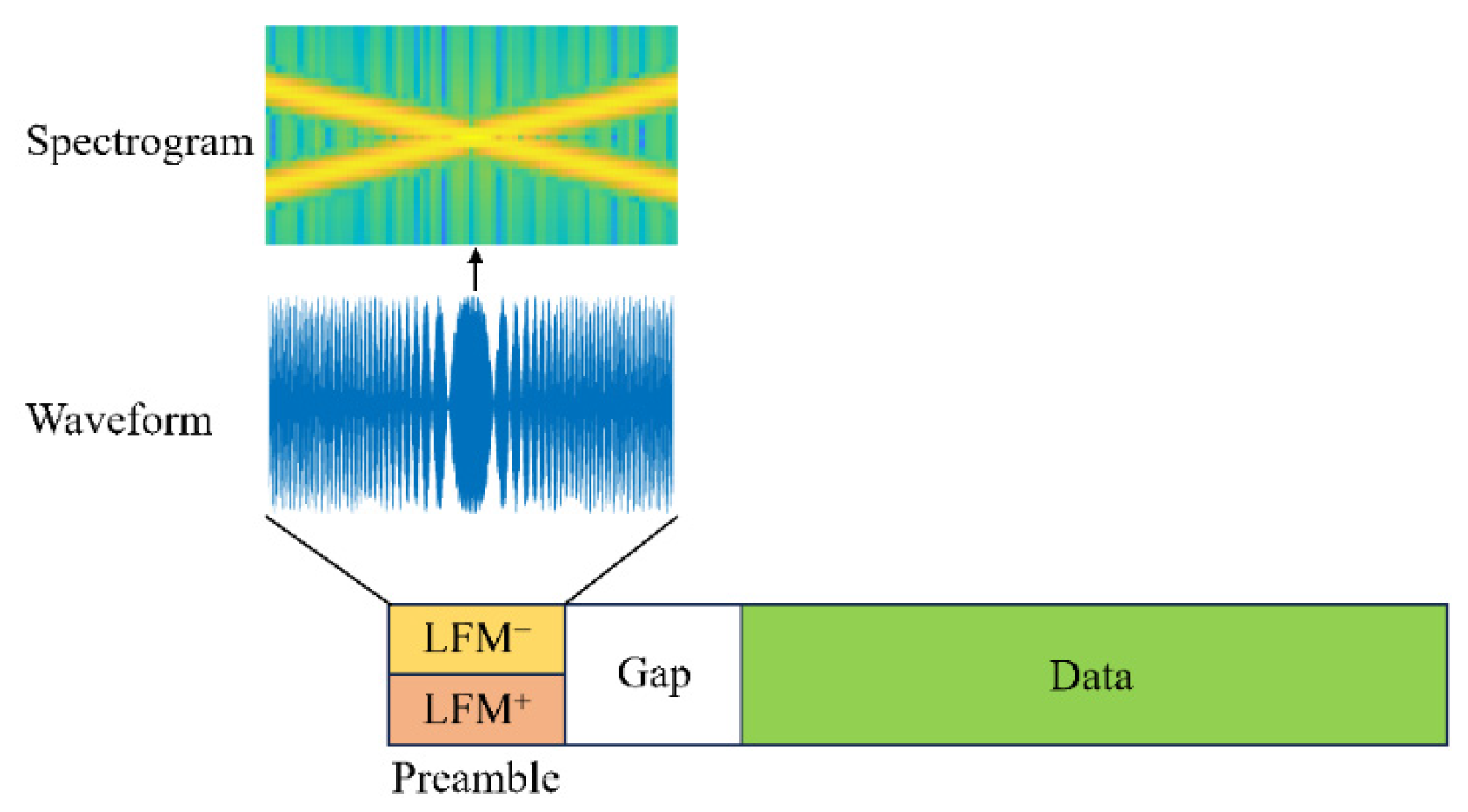
Figure 2 illustrates the structure of the communication frame which consists of a designed preamble signal and the data signal. The designed superimposed-LFM-based preamble signal is composed of a down-sweeping LFM signal and an up-sweeping LFM signal, where LFM and LFM + denote down-sweeping and up-sweeping LFM signals, respectively. Although the up-sweeping and down-sweeping LFM signals are superimposed in the time domain, they can still be identified in the frequency domain. A guard interval is added between the preamble signal and the data signal.
The designed preamble signal, s P (t), can be denoted as
s P ( t ) = s d ( t ) + s u ( t ) 2 , 0 t T P ,
s d ( t ) = cos ( 2 π f H t π k t 2 ) ,
s u ( t ) = cos ( 2 π f L t + π k t 2 ) ,
k = f H f L T P ,
where s d (t) and s u (t) are LFM and LFM + , respectively; f L is the lower bound of the frequency range; f H is the upper bound of the frequency range; and T P is the time duration of the preamble signal.

3.2. The Real-Time Doppler Estimation Algorithm

Using the designed preamble signal, a real-time Doppler estimation algorithm is proposed in this work.
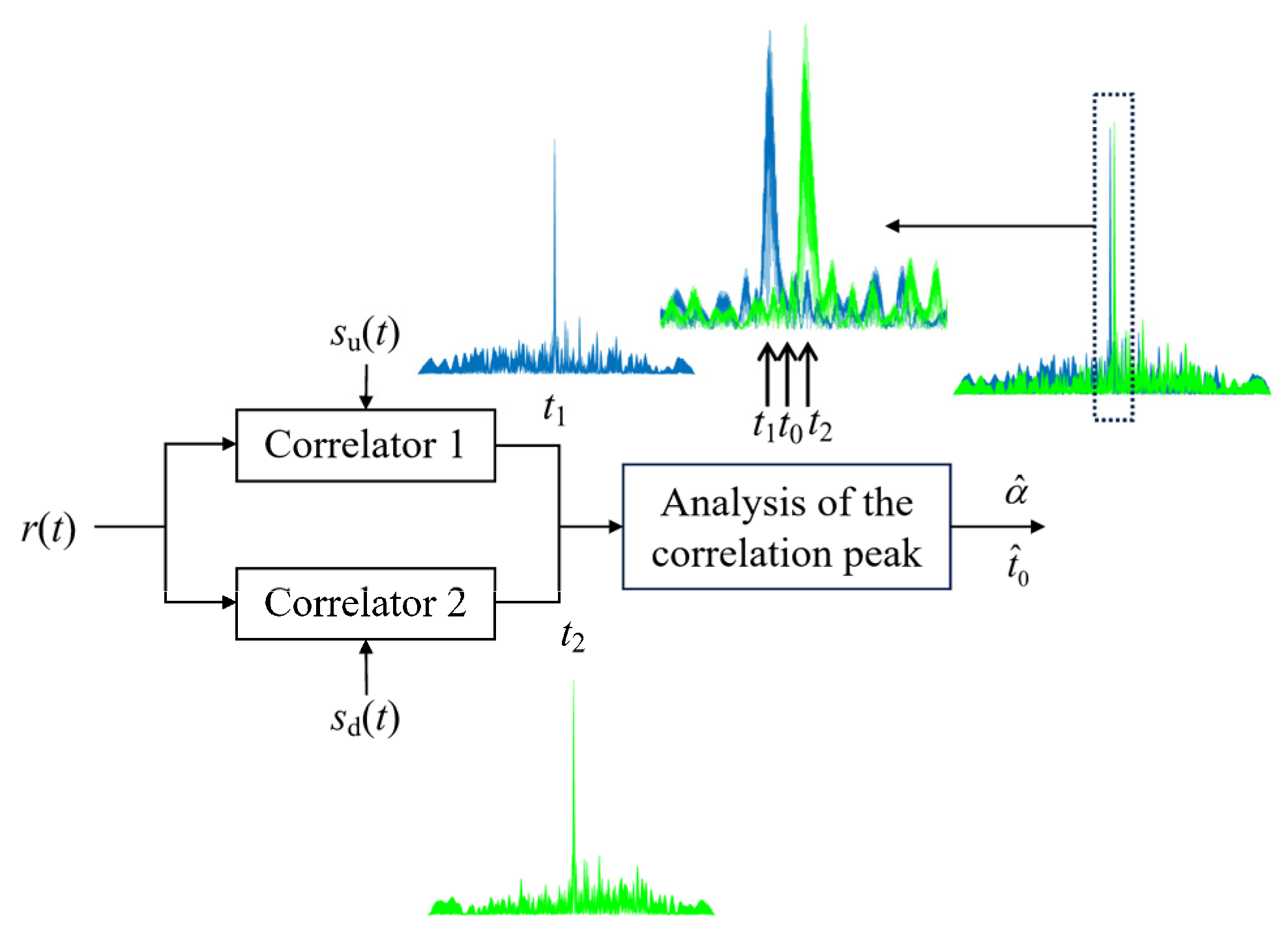
Figure 3 illustrates the structure diagram of the proposed Doppler estimation method, where t 1 and t 2 are the correlation peak positions of correlator 1 and correlator 2, respectively; and t 0 is the start position of the received preamble signal without the Doppler factor.
As shown in Figure 3, two correlators are used to estimate the Doppler factor. In this paper, we consider a realistic Doppler factor level (α < 0.01). Hence, for correlator 1, according to (8), the time offset between the correlation peak position and the start position of the received preamble signal, Δ t 1 , can be obtained as
Δ t 1 = t 1 t 0 = α ( f L + f H ) T P 2 ( f H f L ) .
Similarly, for correlator 2, the time offset between the correlation peak position and the start position of the received preamble signal, Δ t 2 , is
Δ t 2 = t 2 t 0 = α ( f L + f H ) T P 2 ( f L f H ) = α ( f L + f H ) T P 2 ( f H f L ) .
Solving (19) and (20), the estimation of the Doppler factor can be presented as
α ^ = ( f H f L ) ( Δ t 2 Δ t 1 ) ( f H + f L ) T P = ( f H f L ) ( t 2 t 1 ) ( f H + f L ) T P .
Furthermore, by substituting (21) into (19), the estimation of the start time of the received signal can be calculated as
t ^ 0 = t 1 + α ^ ( f L + f H ) T P 2 ( f H f L ) .
One finds from (22) that communication frame synchronization is realized.

3.3. The Enhanced OMP Channel Estimation Algorithm

In this work, a correlation-peak-search-based improved OMP (CPS-IOMP) algorithm is proposed to estimate the channel using the designed preamble signal.
The block diagram of the proposed channel estimation algorithm, which consists of the channel sparsity estimation module and the OMP module, is illustrated in Figure 4. The input signal of the proposed channel estimation algorithm is the received preamble signal after the Doppler compensation with the Doppler factor estimated in (21).
The channel sparsity is estimated according to the excellent autocorrelation characteristic of the designed preamble signal. In the proposed correlation-peak-search-based channel sparsity estimation module, correlation processing is first performed between the Doppler-compensated received preamble signal and the locally generated preamble signal. And then, the correlation peaks are searched. These correlation peaks are mainly caused by the multipath, and the positions of the correlation peaks correspond to the multipath delay. Hence, the positions of the correlation peaks can be used to determine the channel sparsity. The correlation peaks larger than the threshold η are selected.
Let the number of selected correlation peaks be L’. Obviously, L’ is much smaller than L. The corresponding normalized delay of each correlation peak is denoted as c i , i = 1, 2, …, L’. Hence, dictionary matrix A can be simplified as
Λ = [ a c 1 , a c 2 , , a c L ] = [ s P ( 0 c 1 ) s P ( 0 c 2 ) s P ( 0 c L ) s P ( 1 c 1 ) s P ( 1 c 2 ) s P ( 1 c L ) s P ( N 1 c 1 ) s P ( N 1 c 2 ) s P ( N 1 c L ) ] ,
where a i is the (i + 1)th column of matrix A.
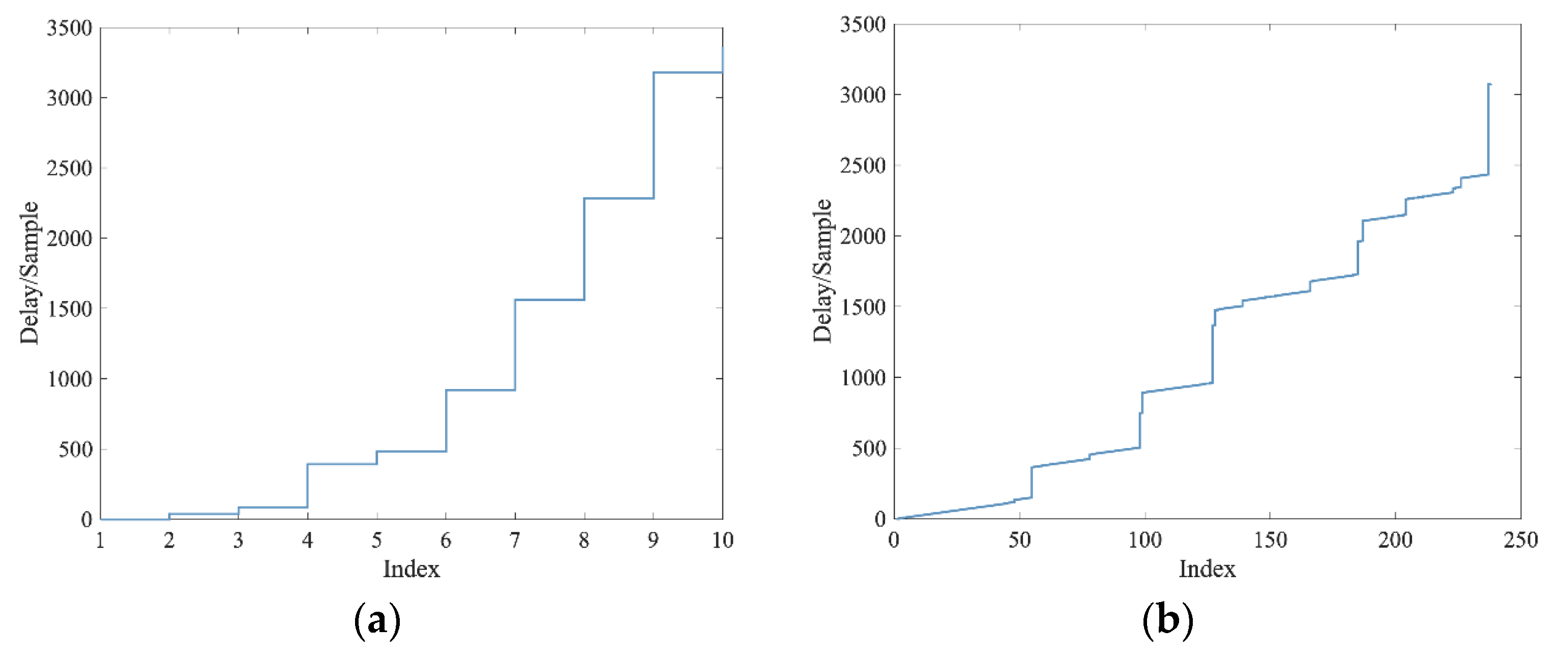
Since the simplified dictionary matrix eliminates some irrelevant paths, the delay corresponding to each column of Λ no longer changes continuously. The jump at the delay corresponding to the multipath is a stair-like change trend with the increase in the index, as shown in Figure 5a. The number of jumps is the estimated channel sparsity. Owing to the noise and large sidelobes in the correlation processing, the actual obtained jump at the delay may be as illustrated in Figure 5b. Comparing Figure 5b with Figure 5a, we observe that the overall trend of the change is basically consistent and the columns corresponding to multipath delay are almost included, although more columns are selected in the actual obtained result. Therefore, with an appropriate threshold, the channel sparsity can be estimated and the simplified dictionary matrix can be constructed by filtering out the columns corresponding to multipath delay.
After obtaining the channel sparsity and the simplified dictionary matrix, the channel state information is estimated with the OMP algorithm in the proposed CPS-IOMP algorithm. The OMP algorithm is an iterative procedure for estimating the channel taps and its coefficients sequentially. The number of iterations is set as the estimated channel sparsity.
At each iteration, the column of the dictionary matrix which has the largest absolute value of correlation with the residual is selected. In the proposed CPS-IOMP algorithm, the index of the selected column of the simplified dictionary matrix can be written as
λ s = arg max i = c 1 , c 2 , , c L | a i , r s 1 | ,
where denotes the inner product operation, | | denotes the absolute value of a scalar, s is the iteration time, r s 1 is the residual vector in the previous iteration, and the initialized residual vector, r 0 , is y P .
Then, the index is added to the support set, . That is,
= { λ s } .
Obviously, the initialized support set is blank.
According to the support set, the coefficients can be measured via the least-squares (LS) method as
h ^ s = Λ [ ] y P ,
where ( ) denotes the Moore–Penrose pseudo-inversion operation and Λ [] denotes the submatrix of Λ with the column index belonging to set .
Finally, the residual vector can be updated as
r s = y P Λ [ ] h ^ s .
The procedure of the CPS-IOMP algorithm is summarized in Algorithm 1.
Algorithm 1: CPS-IOMP algorithm
Input: dictionary matrix, A; received preamble signal after Doppler compensation, y P ; threshold η.
Initialization: residual vector, r 0 = y P ; support set, = Ø.
1: Perform the correlation processing between the received preamble signal after Doppler compensation and the locally generated preamble signal.
2: Search for the correlation peaks with normalized amplitude larger than threshold η.
3: Estimate the channel sparsity k and construct the simplified dictionary matrix Λ .
4: for s = 1 to k do
5: Perform (24);
6: Perform (25);
7: Perform (26);
8: Perform (27);
9: end for
Output:  h ^ k .
For the CPS-IOMP algorithm, the threshold selected in the channel sparsity estimation module impacts both the computational complexity and estimation accuracy. A smaller threshold filters more correlation peaks, which results in more columns in the simplified dictionary matrix and higher computational complexity. In addition, a smaller threshold increases the estimated channel sparsity, which leads to more iterations in the CPS-IOMP algorithm and increases the computational complexity. And an excess estimated sparsity may potentially reduce performance. Conversely, a larger threshold filters fewer correlation peaks, which leads to a lower estimated channel sparsity. When the estimated channel sparsity is too small, both the computational complexity and the performance of the proposed channel estimation algorithm reduce significantly. Hence, the threshold should be selected to achieve a trade-off between computational complexity and estimation performance. In the next section, we determine the selection of the threshold based on the simulation results of the performance of the CPS-IOMP algorithm over different thresholds and computational complexities.

4. Numerical Results and Discussions

In this section, the proposed Doppler estimation algorithm and channel estimation algorithm are validated using the superimposed-LFM-based preamble signal.
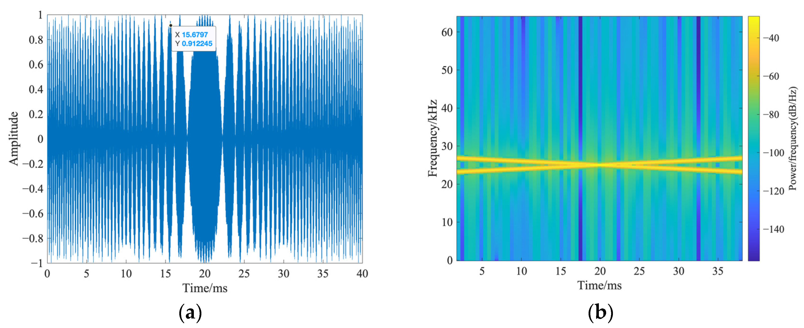
Figure 6 shows the designed superimposed-LFM-based preamble signal, where Figure 6a,b are the waveform and the spectrogram, respectively. In the designed preamble signal, f L = 23 kHz, f H = 27 kHz, and T P = 40 ms. Notably, these parameters are used in the sea trial. The sampling frequency at the receiver, f s , is set as 128 kHz. From Figure 6, we observe that the up-sweeping and down-sweeping LFM signals can still be identified in the frequency domain, although they are superimposed in the time domain.

4.1. Simulation Results

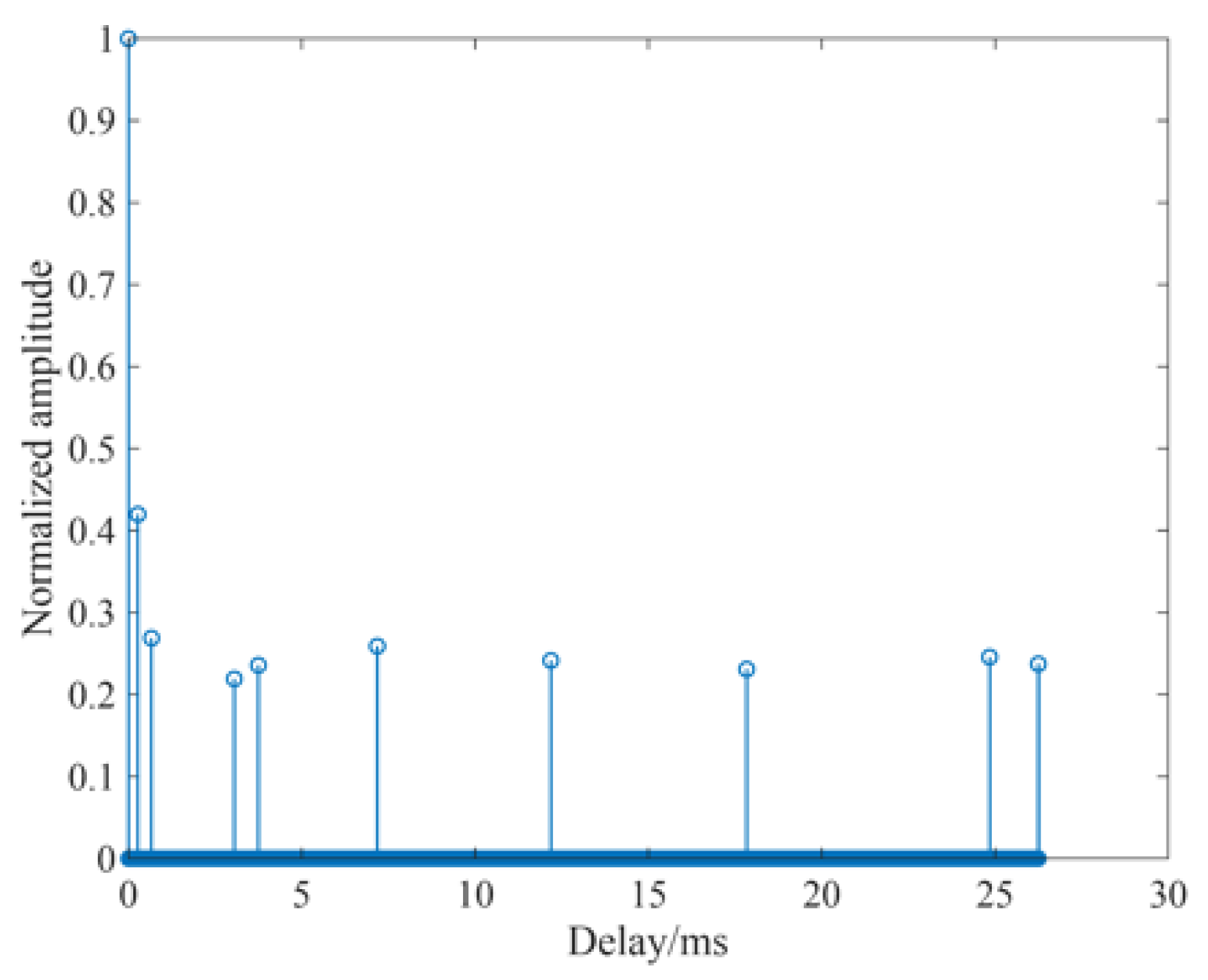
The Bellhop model is used to generate a UWA sparse multipath channel. The water depth is set as 65 m, the sound speed is set as 1545 m/s, the depth of the transmitter is set as 20 m, the depth of the receiver is set as 25 m, and the range of the transmitter–receiver is 1 km. Figure 7 demonstrates the CIR of the generated channel which consists of 10 paths, the maximum multipath delay is about 26 ms, and the maximum attenuation relative to the main path is about 13.2 dB.
The root-mean-square error (RMSE) of the estimated Doppler factor is adopted to evaluate the performance of the Doppler estimation algorithm. The RMSE is defined as
R M S E = E ( | α ^ α | 2 ) ,
where E(·) denotes the mathematical expectation, α is the simulated Doppler factor, and α ^ is the estimated Doppler factor. Thus, the smaller the RMSE of the estimated Doppler factor, the better the performance of the Doppler estimation algorithm.
First, we evaluate the performance of the proposed Doppler estimation algorithm. For comparison, two existing Doppler estimation algorithms, namely the block Doppler estimation algorithm proposed in [5] and the adaptive dual-stage algorithm proposed in [12], are selected. The block estimation algorithm is a classic algorithm and widely used in practical applications. The adaptive dual-stage algorithm is a state-of-the-art algorithm, which is an improvement of the block estimation algorithm.
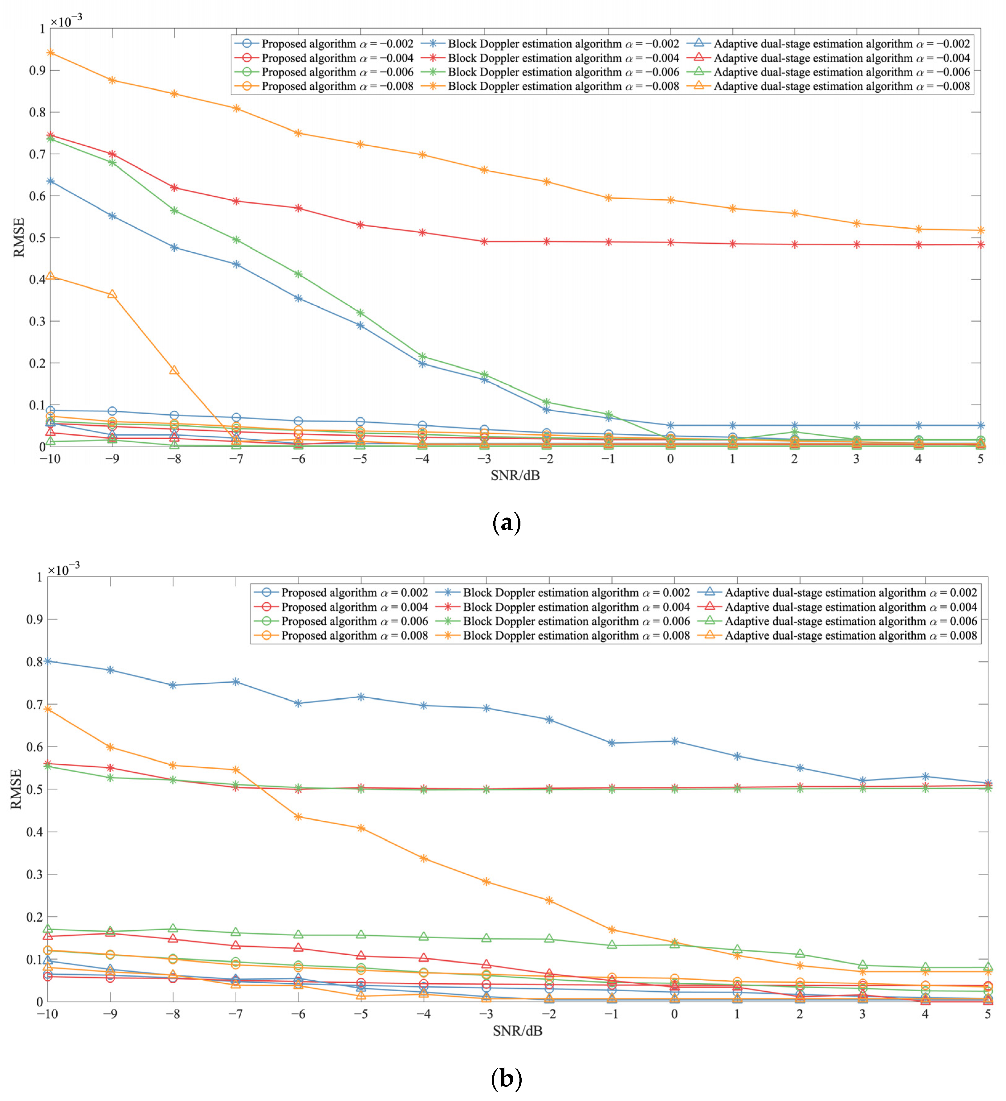
The performance of Doppler factor estimation is shown in Figure 8, where the simulated Doppler factor is negative in Figure 8a and positive in Figure 8b. Each value of the RMSE is averaged with 1000 Monte Carlo simulations. From Figure 8, we observe that the performance of proposed the Doppler factor algorithm is better than that of the block Doppler estimation algorithm. As the signal-to-noise ratio (SNR) is low, the performance of the proposed Doppler factor algorithm improves significantly compared with the block Doppler estimation algorithm. Compared with the adaptive dual-stage algorithm, the estimation performance of the proposed algorithm is slightly worse, especially when the SNR is high. However, the computational complexity of the adaptive dual-stage algorithm is much higher than that of the proposed algorithm. Moreover, since one frame of the signal needs to be stored in order to perform Doppler estimation in two existing Doppler estimation algorithms, the estimation is not real-time. Therefore, the proposed Doppler estimation algorithm has a good comprehensive performance in terms of a lower computational complexity, a better estimation performance, and the possibility of real-time estimation. It is more suitable for practical application.
Moreover, the performance of the proposed Doppler estimation algorithm is stable under different SNRs and Doppler factors, and the estimation error is less than 2 × 10 4 .
The normalized mean square error (NMSE) of the estimated CIR is adopted to evaluate the performance of the channel estimation algorithm. The NMSE is defined as
NMSE = h h ^ 2 2 h 2 2 ,
where 2 denotes the L 2 norm of a vector; h is the simulated CIR; and h ^ is the estimated CIR. Thus, the smaller the NMSE of the estimated CIR, the better the performance of the channel estimation algorithm.
Figure 9 shows the impact of the threshold on the performance of the proposed channel estimation algorithm in terms of NMSE and estimated channel sparsity, where the SNR is 5 dB. Each value of the NMSE and estimated channel sparsity is averaged with 500 Monte Carlo simulations. From Figure 9, we observe that the estimated channel sparsity decreases as the threshold increases. However, as the threshold increases, the NMSE of the CPS-IOMP algorithm decreases and then increases. The NMSE of the CPS-IOMP algorithm reaches the minimum value as the estimated channel sparsity approaches the actual value. Considering the trade-off between the computational complexity and the channel estimation performance, the threshold for the channel sparsity estimation module is set as 0.1. In subsequent simulations and sea trial data analysis, the threshold is set as 0.1.
To verify the performance of the channel estimation method proposed in this paper, we compared it to the OMP algorithm.
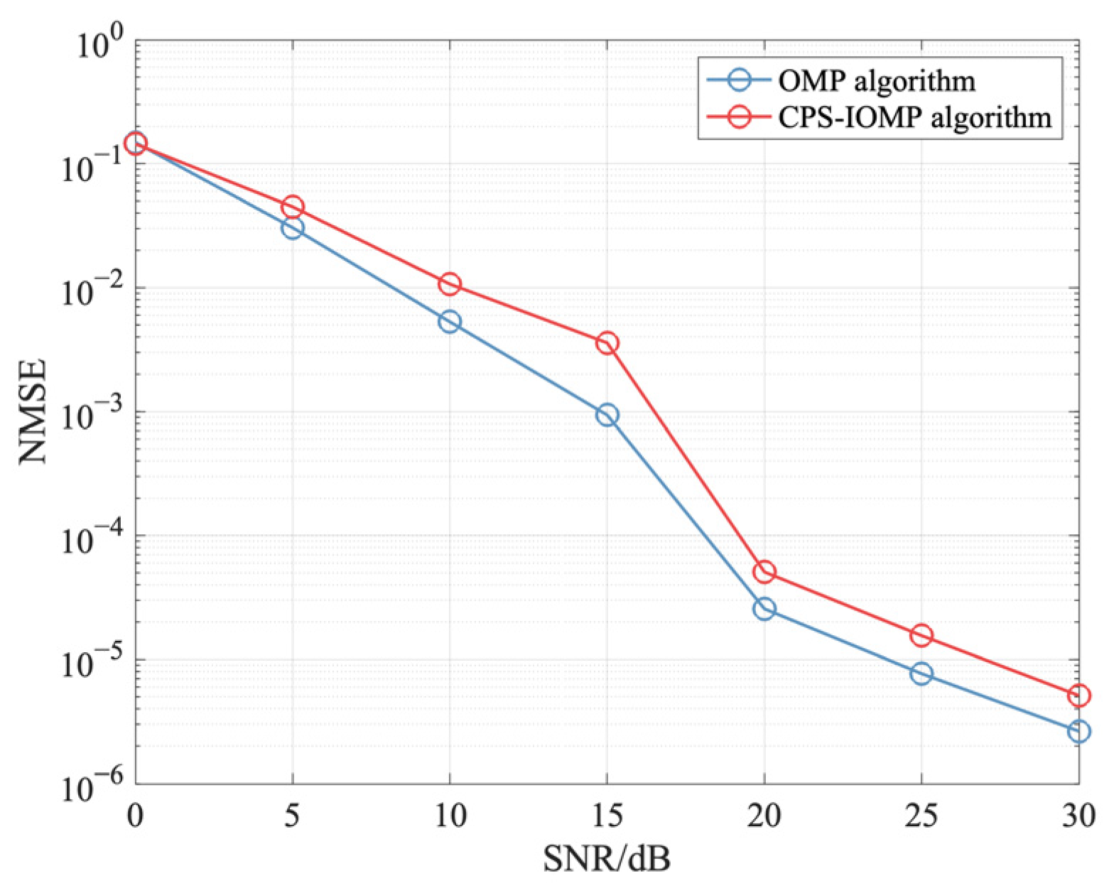
Figure 10 shows the performance of the channel estimation algorithm in terms of the NMSE, where the CIR of the generated channel depicted in Figure 6 is adopted, and the Doppler effect is not considered. Each value of the NMSE is averaged with 500 Monte Carlo simulations. The CPU running time is also listed in Table 1, where the CPU is an Intel i7-9750H.
From Figure 10, we observe that the performance of the proposed CPS-IOMP algorithm in terms of the NMSE is similar to that of the OMP algorithm with known channel sparsity. However, the proposed CPS-IOMP algorithm needs no prior knowledge on channel sparsity.
From Table 1, we observe that the CPU running time of the proposed CPS-IOMP algorithm is less than that of the OMP algorithm, although the channel sparsity estimation module is needed in the proposed channel estimation algorithm. The reason for the efficiency is that the proposed channel estimation algorithm only requires calculating (26) for selected columns. Hence, the computational complexity of the proposed channel estimation algorithm reduces significantly.
Furthermore, considering the implications of practical impairments such as carrier frequency offset (CFO) and sampling frequency offset (SFO) caused by imperfect Doppler compensation, we analyze their effect on the performance of the proposed channel estimation algorithm. Figure 11 shows the impact of the Doppler estimation error on the performance of the proposed channel estimation algorithm in terms of NMSE. Each value of the NMSE is averaged with 500 Monte Carlo simulations.
From Figure 11, we observe that the performance of the proposed channel estimation algorithm obviously deteriorates as the Doppler estimation error exists and the Doppler factor cannot be fully compensated. The larger the Doppler estimation error, the more severe the performance degradation will be. For example, as the Doppler estimation error is 10 5 , the performance still deteriorates significantly, which implies that the proposed algorithm may be more suitable for scenarios without Doppler or with perfect Doppler compensation. However, as shown in Figure 11, when the Doppler estimation error is 10 5 , the performance degradation of the proposed channel estimation algorithm is acceptable. According to the results shown in Figure 8, we can see that when the SNR is greater than 0 dB, the error of the proposed Doppler estimation algorithm is around 10 6 ~ 10 5 , which indicates that the proposed algorithm can effectively improve system performance. The corresponding simulation is conducted next.
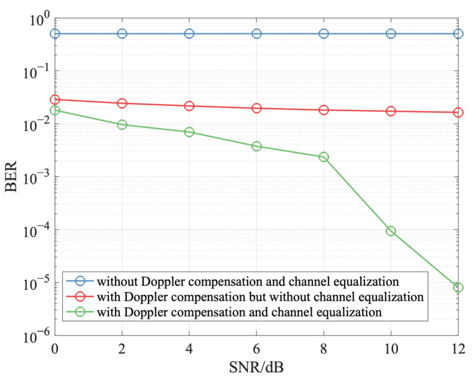
To evaluate the performance of the proposed Doppler factor estimation algorithm and CPS-IOMP algorithm in a UWA communication system, the communication frame structure consists of the designed superimposed-LFM-based preamble signal illustrated in Figure 6 and the data block with 1000 BPSK symbols at a baud symbol rate of 4000. The modulation mode is BPSK, the carrier frequency is 25 kHz, and the bandwidth is 4 kHz. The performance of the UWA communication system in terms of bit error rate (BER) is shown in Figure 12, where the CIR of the generated channel depicted in Figure 6 is adopted, and the Doppler factor is set as 0.004. Each value of BER is averaged with 500 Monte Carlo simulations. From Figure 12, we observe that the BER of the UWA communication system with Doppler compensation and channel equalization is obviously reduced.

4.2. Sea Trial Data Analysis Results

To validate the proposed Doppler factor estimation algorithm, we analyzed the data collected from a UWA mobile communication experiment conducted near the Ross Sea in Antarctica on 25 December 2022. The transmitter was deployed on a moving boat drifting with the ocean current and the depth of the transducer was about 12 m. The receipt was deployed on the seabed at (163°45.42′ E, 74°56.347′ S), and the depth of the transducer was about 130 m. In the sea trial, the communication frame structure, as illustrated in Figure 13, was composed of two up-sweeping LFM signals and one down-sweeping LFM signal. The parameters of LFM signals are consistent with those in the simulations.
The proposed Doppler factor estimation algorithm can be indirectly validated by modifying (20) using the second up-sweeping LFM signal and the third down-sweeping LFM signal. As the time duration of the gap between LFM + and LFM is T GAP , (20) can be modified as
Δ t 2 = t 2 t 0 = α ( f L + f H ) T P 2 ( f L f H ) + T G A P 1 + α = α ( f L + f H ) T P 2 ( f H f L ) + T G A P 1 + α .
Solving (19) and (30), the estimation of the Doppler factor can be obtained as
α ^ = ( t 2 t 1 a ) + ( t 2 t 1 a ) 2 4 a ( T G A P ( t 2 t 1 ) ) 2 a ,
where a = ( f L + f H ) T P f H f L .
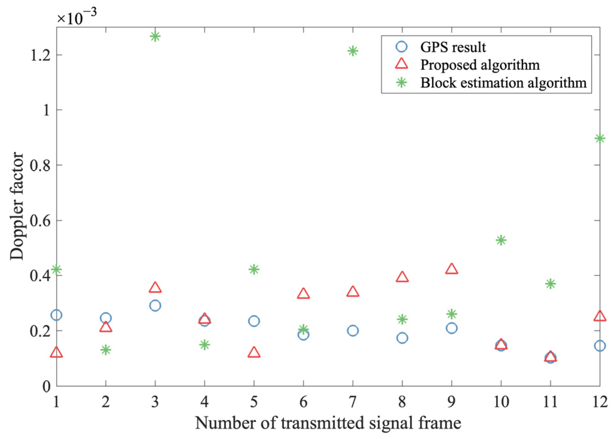
The moving speed of the boat is calculated using the GPS records, and the sound speed in water is about 1440.5 m/s. The actual Doppler factor can be calculated. Figure 14 shows the estimated Doppler factor, where the proposed Doppler factor estimation algorithm and the block estimation algorithm are compared. In Figure 14, the blue circle denotes the calculated actual Doppler factor, the red triangle denotes the estimated Doppler factor with the proposed Doppler factor estimation algorithm, and the green star denotes the estimated Doppler factor with the block estimation algorithm. From Figure 14, we observe that the proposed estimation algorithm can estimate the Doppler factor successfully and outperforms the block estimation algorithm.
To validate the proposed channel estimation algorithm, we analyzed the data collected from a UWA communication experiment conducted in the East China Sea in September 2022. Two UWA communication nodes were deployed at (122°59.025′ E, 30°38.392′ N) and (122°58.283′ E, 30°37.328′ N). The depth of two nodes was about 50 m. The communication frame structure as illustrated in Figure 13 is also adopted.
Generally, the channel temporal coherence function is adopted to characterize the channel variation over time. It is indicated in [32] that the channel temporal coherence can be calculated by
p ( τ ) = E [ h ( t ) h ( t + τ ) ] E [ | h ( t ) | 2 ] E [ | h ( t + τ ) | 2 ] ,
where h(t) is the CIR at geotime t and h(t+τ) is the CIR with a lag time τ. Thus, the larger the channel temporal coherence, the slower the channel variation.
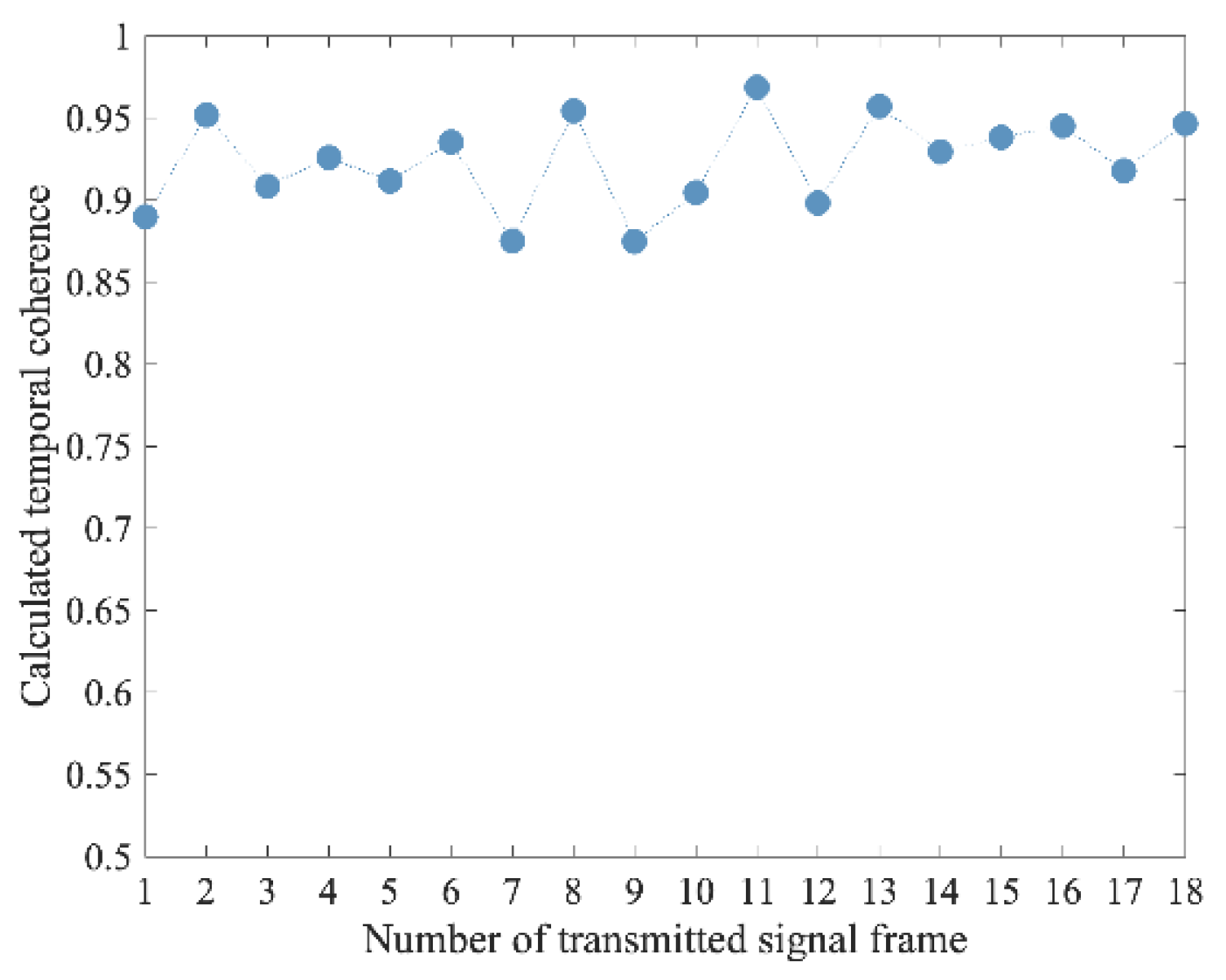
By matched-filtering each received LFM signal with its corresponding transmitted LFM signal, an estimate of the CIR is obtained for each LFM signal within a communication frame. To calculate the temporal coherence, the CIRs estimated by the second LFM + and the third LFM are used. The calculated temporal coherence of a sequence of communication frames is shown in Figure 15. From Figure 15, we observe that the temporal coherence is high (>0.86), which means that the channel almost does not vary during the time duration of the second LFM + and the third LFM . Hence, the assumption that the channel does not vary during the time duration of the second LFM + and the third LFM is justified. To simulate the received signal of the designed superimposed-LFM-based preamble signal, we superimposed the received second LFM + and the received third LFM in each communication frame. The simulated received signal is used to validate the proposed channel estimation algorithm.
Since the actual CIR is unknown, the NMSE of channel estimation is re-defined as
NMSE = y P y ^ P 2 2 y P 2 2 ,
where y ^ P = s P h ^ k .
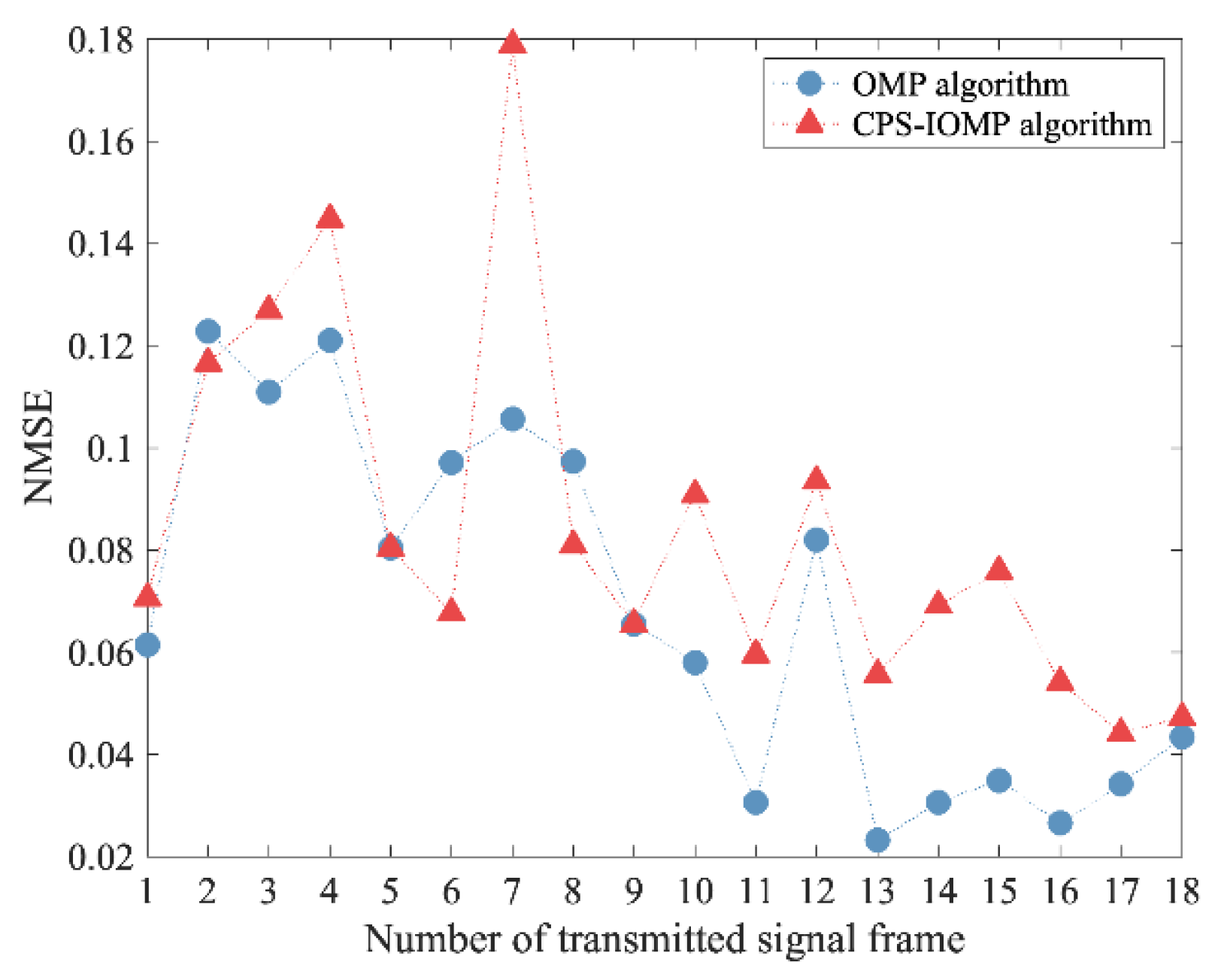
Figure 16 shows the performance of the channel estimation algorithm in terms of NMSE in (33). The CPU running time is also listed in Table 2, where the CPU is an Intel i7-9750H. The channel sparsity for the OMP algorithm is set as 5.
From Figure 16, we observe that the performance of the proposed CPS-IOMP algorithm in terms of NMSE is similar to that of the OMP algorithm.
From Table 2, we observe that the CPU running time of the proposed CPS-IOMP algorithm is less than that of the OMP algorithm. Since the fixed channel sparsity is adopted in the OMP algorithm, the CPU running time of the OMP algorithm is constant for different communication frames. However, the CPU running time of the proposed CPS-IOMP algorithm varies across different communication frames. The reason for the variation in CPU running time is that the number of iterations in the proposed CPS-IOMP algorithm depends on the estimated channel sparsity. Owing to the variation in channel sparsity, the CPU running time varies slightly across different communication frames. In addition, the dimension of the simplified dictionary matrix constructed from different communication frames is different, which also leads to the variation in CPU running time across different communication frames. Furthermore, although it is assumed that the channel does not vary during the time duration of the second LFM + and the third LFM in each communication frame, the time interval between two communication frames is on the order of seconds, and the channel may vary.

5. Conclusions

In this paper, a preamble signal, a superimposed-LFM-based preamble signal, was designed for real-time Doppler estimation. Based on the designed preamble signal, a Doppler factor estimation algorithm and an enhanced channel estimation algorithm were proposed. In the proposed Doppler estimation algorithm, the relationship between the Doppler factor and the peak position offset of the matched filter was utilized to estimate the real-time Doppler factor. For the CPS-IOMP algorithm, the excellent autocorrelation characteristic of the designed preamble signal was used to estimate the channel sparsity, and a simplified dictionary matrix was constructed to reduce the computational complexity. The CIR was estimated using the OMP algorithm with the simplified dictionary matrix. The designed preamble signal, the proposed Doppler estimation algorithm, and the proposed channel estimation algorithm were validated by simulations and sea experiments. Numerical results show that the proposed Doppler estimation algorithm achieves a more accurate estimation performance. Furthermore, the proposed CPS-IOMP algorithm performs well in terms of good channel estimation performance and less CPU running time.

Author Contributions

Conceptualization, C.L., Q.S. and H.C.; methodology, Q.S., C.L. and H.C.; software, C.L.; validation, Q.S. and C.L.; formal analysis, C.L., Q.S. and H.C.; investigation, C.L. and Q.S.; resources, H.C.; data curation, C.L., Q.S. and L.X.; writing—original draft preparation, C.L. and H.C.; writing—review and editing, C.L., H.C. and L.X.; supervision, H.C. and L.X.; project administration, H.C. and L.X.; funding acquisition, H.C. and L.X. All authors have read and agreed to the published version of the manuscript.

Funding

This work was partially supported by the National Key Research and Development Program of China, grant number 2021YFC2801201; the National Natural Science Foundation of China, grant number 62271442 and grant number 42227901; the Science and Technology Department of Zhejiang Province, grant number LGG22F010007; and the Natural Science Foundation of Zhejiang Province, grant number LZ23F010006.

Institutional Review Board Statement

Not applicable.

Informed Consent Statement

Not applicable.

Data Availability Statement

Dataset available on request from the authors.

Conflicts of Interest

The authors declare no conflicts of interest.

References

  1. Kilfoyle, D.B.; Baggeroer, A.B. The state of the art in underwater acoustic telemetry. IEEE J. Oceanic Eng. 2000, 25, 4–27. [Google Scholar] [CrossRef]
  2. Stojanovic, M.; Catipovic, J.A.; Proakis, J.G. Phase-coherent digital communications for underwater acoustic channels. IEEE J. Oceanic Eng. 1994, 19, 100–111. [Google Scholar] [CrossRef]
  3. Li, B.; Tong, F.; Li, J.-H.; Zheng, S.-Y. Cross-correlation quasi-gradient Doppler estimation for underwater acoustic OFDM mobile communications. Appl. Acoust. 2022, 190, 108640. [Google Scholar] [CrossRef]
  4. Johnson, M.; Freitag, L.; Stojanovic, M. Improved Doppler tracking and correction for underwater acoustic communications. In Proceedings of the 1997 IEEE International Conference on Acoustics, Speech, and Signal Processing, Munich, Germany, 21–24 April 1997; pp. 575–578. [Google Scholar]
  5. Sharif, B.S.; Neasham, J.; Hinton, O.R.; Adams, A.E. A computationally efficient Doppler compensation system for underwater acoustic communications. IEEE J. Oceanic Eng. 2000, 25, 52–61. [Google Scholar] [CrossRef]
  6. Lin, W.; Zhang, X.; Huang, J. Doppler processing method in multicarrier coherent underwater acoustic communication. J. Northwest. Polytech. Univ. 2005, 23, 520–524. [Google Scholar]
  7. Zhang, X. Simulation research on Doppler frequency shift compensation in underwater acoustic communication. J. Syst. Simul. 2005, 17, 1172–1174. [Google Scholar]
  8. Huang, J.; Guo, S.; Guo, Z.; Chen, G. Doppler compensation for underwater acoustic broadband signal. Tech. Acoust. 2009, 28, 99–103. [Google Scholar]
  9. He, C.; Huang, J.; Meng, J.; Zhang, Q. Accurate Doppler factor estimation for multipath underwater acoustic channels. Audio Eng. 2010, 34, 57–59. [Google Scholar]
  10. Trubuil, J.; Chonavel, T. Accurate Doppler estimation for underwater acoustic communications. In Proceedings of the 2012 Oceans—Yeosu, Yeosu, Republic of Korea, 21–24 May 2012; pp. 1–5. [Google Scholar]
  11. Zheng, S.; Tong, F.; Li, B.; Tao, Q.; Song, A.; Zhang, F. Design and evaluation of an acoustic modem for a small autonomous unmanned vehicle. Sensors 2019, 19, 2923. [Google Scholar] [CrossRef] [PubMed]
  12. Samir, A.; Eldiwany, B.; ElMoslimany, A.; Nafie, M.; El-Sherif, A.A.; ElBatt, T. On the Design of a High Data Rate Underwater Acoustic Receiver. In Proceedings of the 2022 5th International Conference on Communications, Signal Processing, and their Applications, Cairo, Egypt, 27–29 December 2022; pp. 1–7. [Google Scholar]
  13. Zhang, X.; Kong, F.; Feng, H. Frequency offset estimation and synchronization of underwater acoustic communication using hyperbolic frequency modulation signal. Tech. Acoust. 2010, 29, 210–213. [Google Scholar]
  14. Wang, K.; Chen, S.; Liu, C.; Liu, Y.; Xu, Y. Doppler estimation and timing synchronization of underwater acoustic communication based on hyperbolic frequency modulation signal. In Proceedings of the 2015 IEEE 12th International Conference on Net-working, Sensing and Control, Taipei, Taiwan, 9–11 April 2015; pp. 75–80. [Google Scholar]
  15. Zhao, S.; Yan, S.; Xu, L. Doppler estimation based on HFM signal for underwater acoustic time-varying multipath channel. In Proceedings of the 2019 IEEE International Conference on Signal Processing, Communications and Computing, Dalian, China, 20–22 September 2019; pp. 1–6. [Google Scholar]
  16. Xin, M.; Li, W.; Wang, X.; Zhang, Y.; Xu, L. Preamble design with HFMs for underwater acoustic communications. In Proceedings of the 2018 MTS/IEEE OCEANS—Kobe, Kobe, Japan, 28–31 May 2018; pp. 1–5. [Google Scholar]
  17. Wei, R.; Li, X.; Fu, Y.; Ma, X. Performance analysis on the speed spectrum estimation based on dual-HFM waveform. EURASIP J. Adv. Signal Process. 2022, 2022, 125. [Google Scholar] [CrossRef]
  18. Dubey, N.; Pandit, A. A comprehensive review on channel estimation in OFDM system. Int. J. Online Sci. 2019, 5, 1–6. [Google Scholar] [CrossRef]
  19. Gong, G.; Yao, W. Adaptive estimation of sparse channel based on modified RLS for coherent underwater acoustics communications. Appl. Acoust. 2022, 192, 108745. [Google Scholar] [CrossRef]
  20. Berger, C.R.; Zhou, S.; Preisig, J.C.; Willett, P. Sparse channel estimation for multicarrier underwater acoustic communication: From subspace methods to compressed sensing. IEEE Trans. Signal Process. 2010, 58, 1708–1721. [Google Scholar] [CrossRef]
  21. Pati, Y.C.; Rezaiifar, R.; Krishnaprasad, P.S. Orthogonal matching pursuit: Recursive function approximation with applications to wavelet decomposition. In Proceedings of the IEEE 27th Asilomar Conference on Signals, Systems and Computers, Pacific Grove, CA, USA, 1–3 November 1993; pp. 40–44. [Google Scholar]
  22. Jiang, W.; Tong, F.; Zhu, Z. Exploiting rapidly time-varying sparsity for underwater acoustic communication. IEEE Trans. Veh. Technol. 2022, 71, 9721–9734. [Google Scholar] [CrossRef]
  23. Wang, Z.; Li, Y.; Wang, D.; Ouyang, D.; Huang, Y. A-OMP: An Adaptive OMP Algorithm for Underwater Acoustic OFDM Channel Estimation. IEEE Wirel. Commun. Lett. 2021, 10, 1761–1765. [Google Scholar] [CrossRef]
  24. Jia, S.; Zou, S.; Zhang, X.; Tian, D.; Da, L. Multi-block sparse Bayesian learning channel estimation for OFDM underwater acoustic communication based on fractional Fourier transform. Appl. Acoust. 2022, 192, 108721. [Google Scholar] [CrossRef]
  25. Jia, S.; Zou, S.; Zhang, X.; Da, L. Underwater acoustic channel estimation based on sparse Bayesian learning algorithm. IEEE Access 2023, 11, 7829–7836. [Google Scholar] [CrossRef]
  26. Preisig, J.C.; Deane, G.B. Surface wave focusing and acoustic communications in the surf zone. J. Acoust. Soc. Am. 2004, 116, 2067–2080. [Google Scholar] [CrossRef]
  27. Siderius, M.; Porter, M.B.; Hursky, P.; McDonald, V. Modeling Doppler effects for acoustic communications. J. Acoust. Soc. Am. 2006, 119, 3397. [Google Scholar] [CrossRef]
  28. Mason, S.F.; Berger, C.R.; Zhou, S.; Willett, P. Detection, synchronization, and Doppler scale estimation with multicarrier waveforms in underwater acoustic communication. IEEE J. Sel. Areas Commun. 2008, 26, 1638–1649. [Google Scholar] [CrossRef]
  29. Tufts, D.W.; Ge, H.; Umesh, S. Fast maximum likelihood estimation of signal parameters using the shape of the compressed likelihood function. IEEE J. Oceanic Eng. 1993, 18, 388–400. [Google Scholar] [CrossRef]
  30. Cook, C.E.; Bernfeld, M. Radar Signals: An Introduction to Theory and Application; Academic Press Inc: New York, NY, USA, 1967. [Google Scholar]
  31. Bajwa, W.U.; Haupt, J.D.; Raz, G.M.; Wright, S.J.; Nowak, R.D. Toeplitz-structured compressed sensing matrices. In Proceedings of the 2007 IEEE/SP 14th Workshop on Statistical Signal Processing, Madison, WI, USA, 26–29 August 2007; pp. 294–298. [Google Scholar]
  32. Yang, T.-C. Properties of underwater acoustic communication channels in shallow water. J. Acoust. Soc. Am. 2012, 131, 129–145. [Google Scholar] [CrossRef] [PubMed]
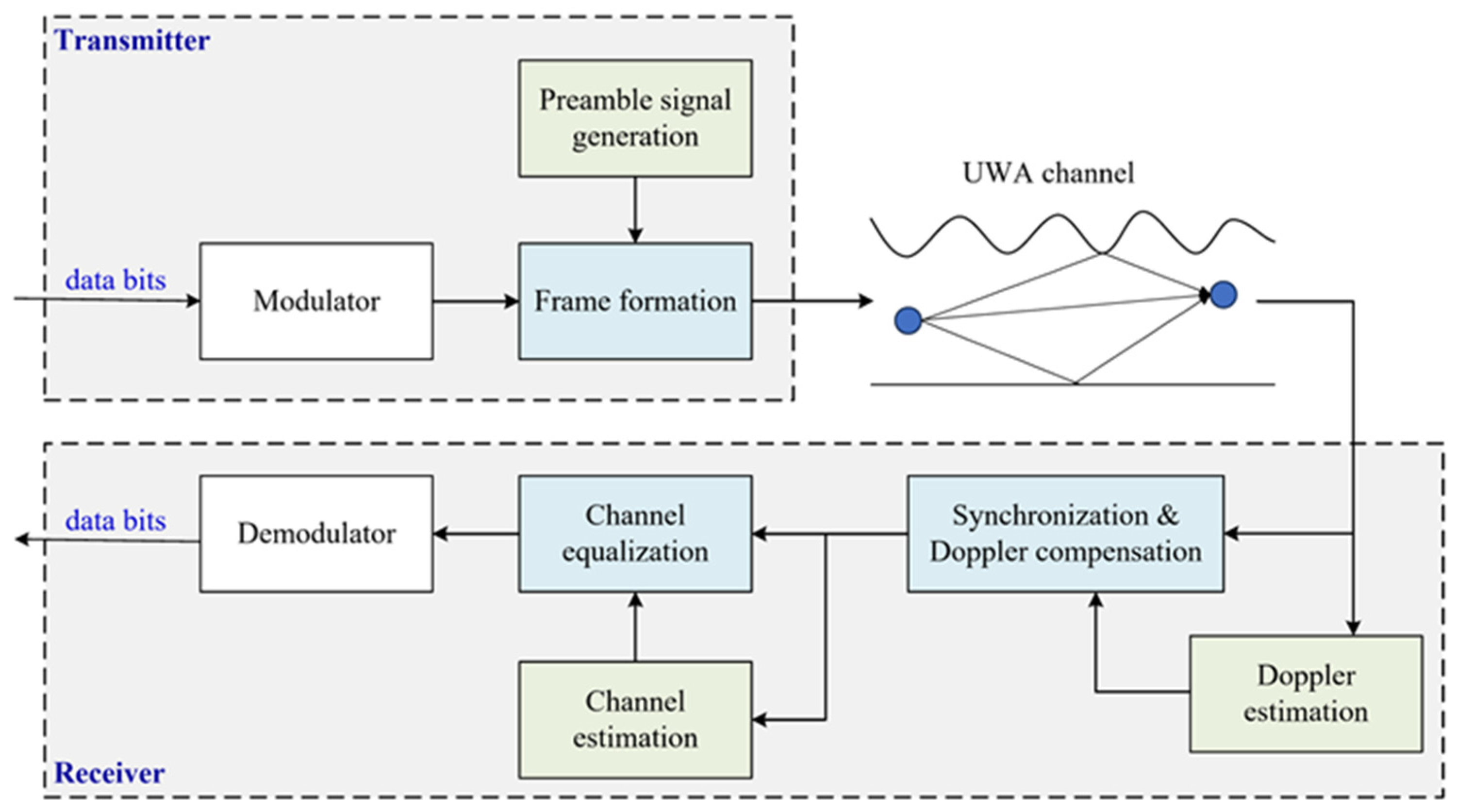
Figure 1. The block diagram of the UWA communication system.
Jmse 12 00338 g001
Figure 2. The communication frame structure.
Jmse 12 00338 g002
Figure 3. The structure for Doppler estimation.
Jmse 12 00338 g003
Figure 4. The block diagram of proposed enhanced channel estimation algorithm.
Jmse 12 00338 g004
Figure 5. The change in corresponding delay along with the increase in the column index of simplified dictionary matrix. (a) Ideal result; (b) actual result.
Jmse 12 00338 g005
Figure 6. The designed superimposed-LFM-based preamble signal. (a) Waveform; (b) spectrogram.
Jmse 12 00338 g006
Figure 7. CIR of generated channel.
Jmse 12 00338 g007
Figure 8. RMSE of Doppler estimation algorithms. (a) Doppler factor is negative; (b) Doppler factor is positive.
Jmse 12 00338 g008
Figure 9. The impact of the threshold on the performance of proposed channel estimation algorithm (SNR = 5 dB).
Jmse 12 00338 g009
Figure 10. The performance of channel estimation method in terms of NMSE.
Jmse 12 00338 g010
Figure 11. The impact of Doppler estimation error on the performance of proposed channel estimation method.
Jmse 12 00338 g011
Figure 12. The performance of UWA communication system in terms of BER.
Jmse 12 00338 g012
Figure 13. The communication frame structure in the sea trial conducted near the Ross Sea in Antarctica.
Jmse 12 00338 g013
Figure 14. The estimated Doppler factor.
Jmse 12 00338 g014
Figure 15. The calculated temporal coherence.
Jmse 12 00338 g015
Figure 16. The performance of channel estimation algorithms in terms of NMSE in (33).
Jmse 12 00338 g016
Table 1. The performance of channel estimation method in terms of CPU running time.
SNR/dBOMP AlgorithmCPS-IOMP Algorithm
00.505 s0.261 s
50.490 s0.282 s
100.497 s0.273s
150.488 s0.291 s
200.491 s0.304 s
250.490 s0.285 s
300.489 s0.285 s
Table 2. The comparison of CPU running time for different channel estimation algorithms.
No. of FramesOMP AlgorithmCPS-IOMP AlgorithmNo. of FramesOMP AlgorithmCPS-IOMP Algorithm
138.445 ms28.315 ms1038.427 ms28.021 ms
238.420 ms33.594 ms1138.246 ms26.643 ms
338.646 ms28.743 ms1238.444 ms26.578 ms
438.566 ms27.206 ms1338.385 ms27.077 ms
538.417 ms30.495 ms1438.570 ms26.110 ms
638.445 ms35.387 ms1538.322 ms26.941 ms
738.402 ms27.462 ms1638.180 ms27.964 ms
838.568 ms33.447 ms1738.385 ms28.840 ms
938.358 ms30.266 ms1838.691 ms29.185 ms
Disclaimer/Publisher’s Note: The statements, opinions and data contained in all publications are solely those of the individual author(s) and contributor(s) and not of MDPI and/or the editor(s). MDPI and/or the editor(s) disclaim responsibility for any injury to people or property resulting from any ideas, methods, instructions or products referred to in the content.