Article

Real-Time Digital Twin of Ship Structure Deformation Field Based on the Inverse Finite Element Method

1
State Key Laboratory of Ocean Engineering, Shanghai Jiao Tong University, Shanghai 200240, China
2
Institute of Marine Equipment, Shanghai Jiao Tong University, Shanghai 200240, China
3
China Ship Scientific Research Center, Wuxi 214082, China
*
Authors to whom correspondence should be addressed.
J. Mar. Sci. Eng. 2024, 12(2), 257; https://doi.org/10.3390/jmse12020257
Submission received: 4 January 2024 / Revised: 27 January 2024 / Accepted: 28 January 2024 / Published: 31 January 2024
(This article belongs to the Special Issue Advanced Analysis of Marine Structures—Edition II)

Abstract

:
Digital twins, an innovative technology propelled by data and models, play a seminal role in the digital transformation and intelligent upgrade of ships. This study introduces a digital twin methodology for the real-time monitoring of ship structure deformation fields, based on finite discrete strain data, and a visualization tool framework is developed using virtual reality technology. First, the inverse Finite Element Method (iFEM) is employed to derive the deformation field of the ship structure in real time using sensor strain data. Secondly, the deformation field data obtained based on the iFEM algorithm is converted into general visualization data conducive to interpretation within virtual reality (VR) applications. Lastly, a digital twin software tool is built to enable synchronous responses and interactions between the virtual scene and the physical scene, directly superposing particular virtual objects (data acquired by sensors, computer-aided design (CAD) virtual models, and deformation field cloud images) onto the physical scene in real time. The digital twin tool embodies a virtual reality visualization system framework integrating the physical data measurement, reconstruction, analysis, expression, storage, rendering, and interaction of deformation field data. Through practical application, the flexibility, effectiveness, and compatibility of the developed prototype tool are verified. According to the results, the system can enhance the efficiency of scientific communication, model validation, and interdisciplinary sharing during the analysis and evaluation of the mechanical properties of ship structures.

1. Introduction

In the current era of digitization sweeping across the maritime industry, digital twins have emerged as a crucial component. The domain of marine commerce is considerably impacted by burgeoning globalization tendencies, and in this context, solutions stemming from digital twins emerge as significant pillars of support. These solutions enable shipbuilding and shipping enterprises to proficiently grapple with sundry challenges, including but not limited to escalating delivery expenses and political compulsions toward decarbonization [1]. These tools serve as significant assets bolstering digitization initiatives. Structural health monitoring (SHM) is a multidisciplinary technical field offering reliable insights into the mechanical behavior of structures under load using measurement data from sensor systems, thus facilitating decision support for structural safety evaluations. Existing stress monitoring systems of hull structures mainly use limited and discrete strain sensors placed directly at monitoring points, which makes it difficult to obtain the full field information of the hull structure and cannot provide a complete stress state description of each detailed structure in the whole ship [2,3,4,5,6,7,8].
With the advent of digital twins, a concept that has rapidly risen to prominence, conducting health and safety evaluations rooted in twin models is gradually gaining traction as a focal point of research. In the recent chronological sphere, initial applications of digital twins within the maritime domain have surfaced [9,10,11,12]. The literature evidences the usage of digital twins in the realm of shipping, bifurcating it into two primary classifications [13]. The first category pertains to observation, calibration, and decision support integral to ship operation and modulation. For instance, Coraddu et al. [14] established a numerical model anchored in machine learning to quantify the velocity of damage caused by marine fouling. However, the paradigm necessitated an ample corpus of sample data for the efficient training of the model. The second category is applicable to system integration testing and training. Tofte et al. [15] delineated a simulation system encapsulating virtual humans in the ship pipe installation process, touted for its efficacy in hardware testing and operational training. The utilization of digital twin technology in evaluating structural safety remains in the nascent stages. Bernasconi et al. amalgamated finite element analysis with augmented reality, proffering a twin model dedicated to monitoring fatigue crack evolution in metal composite bonded connections founded on measured strain data [16]. Schirmann et al. [17] instituted a digital twin system for estimating hull structure fatigue, predicated on measured wave response data, serving as an evaluation tool for cumulative impairment endured by the ship.
Leveraging a strain sensor network measurement system to mirror the displacement field of a structure in real time, colloquially known as shape-sensing, constitutes an integral research tactic in SHM. In 2004, LR [18] proffered a scheme for sensor configuration specifically crafted for typical hull structure surveillance in bulk carriers or oil tankers. Classification societies such as the American Bureau of Shipping and Det Norske Veritas have established protocols for sensor types, measurement precision, and data retention requisites for hull monitoring systems [19]. Majewska et al. [20] conferred a methodology for contemporaneous strain/stress monitoring of a sailing ship’s foremast employing Fiber Bragg Grating (FBG) sensors. In a notable innovation, Tessler and Spangler [21,22] at NASA Langley Research Centre developed a groundbreaking shape- and stress-sensing algorithm known as iFEM. The utility and precision of the iFEM framework in assessing structural deformation fields have been duly validated [23,24,25,26]. Kefal et al. [27] employed the strain data obtained via finite element analysis as input data procured through the finite element analysis as input data within the iFEM algorithm, actualizing deformation surveillance in a typical chemical tanker.
One of the main purposes of employing digital twin models for ship-structure health monitoring is to extract and exploit efficacious data to the maximum possible extent. Commercial software platforms such as CEI Ensight [28] and GLView VTFx [29] intensify the demand for the visual interaction of finite element analysis (FEA) data in virtual reality environments to a certain extent. However, limited interdisciplinary interfaces and non-open-source features limit the application of user innovation scenarios. With the development of VR technology, it is possible to reproduce the real processes of mechanical phenomena. Song et al. developed the middleware CAE2VR [30], a tool adept at transmuting FEA data into virtual visualization files, subsequently crafting a system to disseminate limited heterogeneous FEA data within a virtual reality milieu. Cho et al. [31] proposed a scheme for FEA data conversion and lightweight representation, thereby augmenting the dissemination of FEA outcomes. Taking advantage of the superior memory capacity inherent in supercomputers, Liu et al. [32] transformed the .ODB result file, computed by the Abaqus 6.14 software, into a .vtk visualization file using a Python script, thereby facilitating the parallel visualization of large-scale FEA results in the Paraview commercial software. Through the application of neural networks, Hambli et al. [33] forecasted the real-time deformation of tennis balls and rackets during the collision process, in which users can feel the impact load of the racket through a haptic glove in a virtual reality environment. Although the above-mentioned research has achieved rapid responses to prediction results by training surrogate models, it is still limited by the scale of the finite element model, which may produce unreliable results for untrained inputs. Deciphering ways to streamline interactions and disseminate FEA data in pragmatic applications continues to pose a formidable challenge [33,34,35,36].
Limited by the current level of computer technology, one of the major problems in ship strength digital twin research is how to obtain the global field deformation results of the structure based on limited strain measurement points. Assessing and overseeing the safety status of any structure, such as a ship, typically requires an examination of its inherent mechanical properties. This analysis often involves the development of a finite element model of the target structure, or a reduced-order variant thereof, or the implementation of deep learning techniques. The unwieldy nature of finite element simulations results in the technology falling short of meeting the exigencies for swift response in the monitoring sequence. The adoption of a reduced-order model necessitates a considerable amount of preparation work, demanding repetition when the target structure varies. Deep learning methods require training with an extensive volume of samples, but they may yield unreliable outcomes for untrained inputs. A common feature amongst these three methods is the disjunction between numerical computations and physical scenes.
This paper aims to explore the feasibility of employing limited discrete strain measurement data within physical scenes to effectuate the real-time reconstruction of the structural deformation field, ultimately actualizing the potential of a virtual–real fusion digital twin monitoring system. The self-developed digital twin tool commences with the values gathered from strain gauges on the investigated structures, proceeding with an analysis based upon the iFEM framework. Following the reconstruction of the deformation field, the data are subsequently provided to the VR system to achieve an integration of the monitoring, analysis, and visualization processes. Given that the hull primarily consists of welded thin plate structures, numerical simulations generally utilize quadrilateral or hexahedral meshes to ensure precise computations. Accordingly, our study adopts a four-node inverse-shell element formulation based on Mindlin’s first-order plate theory. Differing from the traditional iterative process of nonlinear numerical simulations, the iFEM method presented herein utilizes real-time measured strain data. This methodology is particularly suited to reconstructing the deformation field during a structure’s linear elastic stage, excluding considerations of material or geometric nonlinearity.
The remaining sections of this paper are organized as follows. In Section 2, the fundamental concepts and overview of the extant digital twin system are explained, and a digital twin framework of virtual–real fusion, a deformation field reconstruction algorithm based on the inverse finite element, and a visualization strategy for the virtual scenes are established. Section 3 introduces the real-time virtual–real interactive platform for ship structure mechanic testing, constructed using the digital twin methodology and validated through comparative verification via physical model test case studies. This section incorporates discussions on various technical issues related to the monitoring of structural mechanical properties, such as the analysis of deformation fields, fusion of physical and virtual data, and virtual visualization of deformation fields. Finally, Section 4 draws the primary conclusions and summarizes the insights gleaned from this study.

2. Methodology

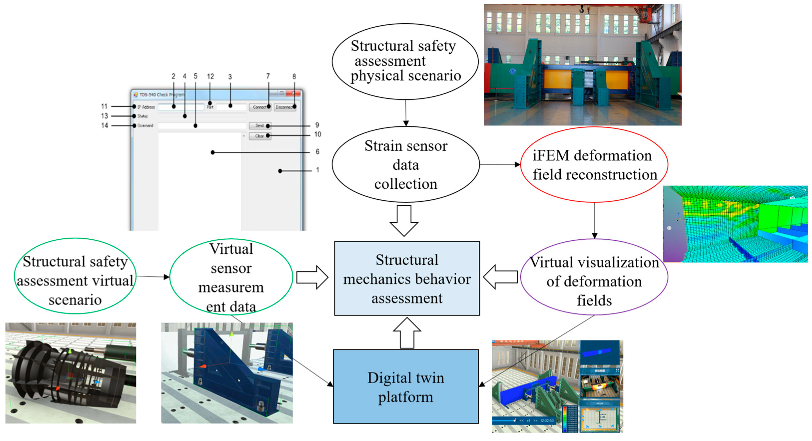
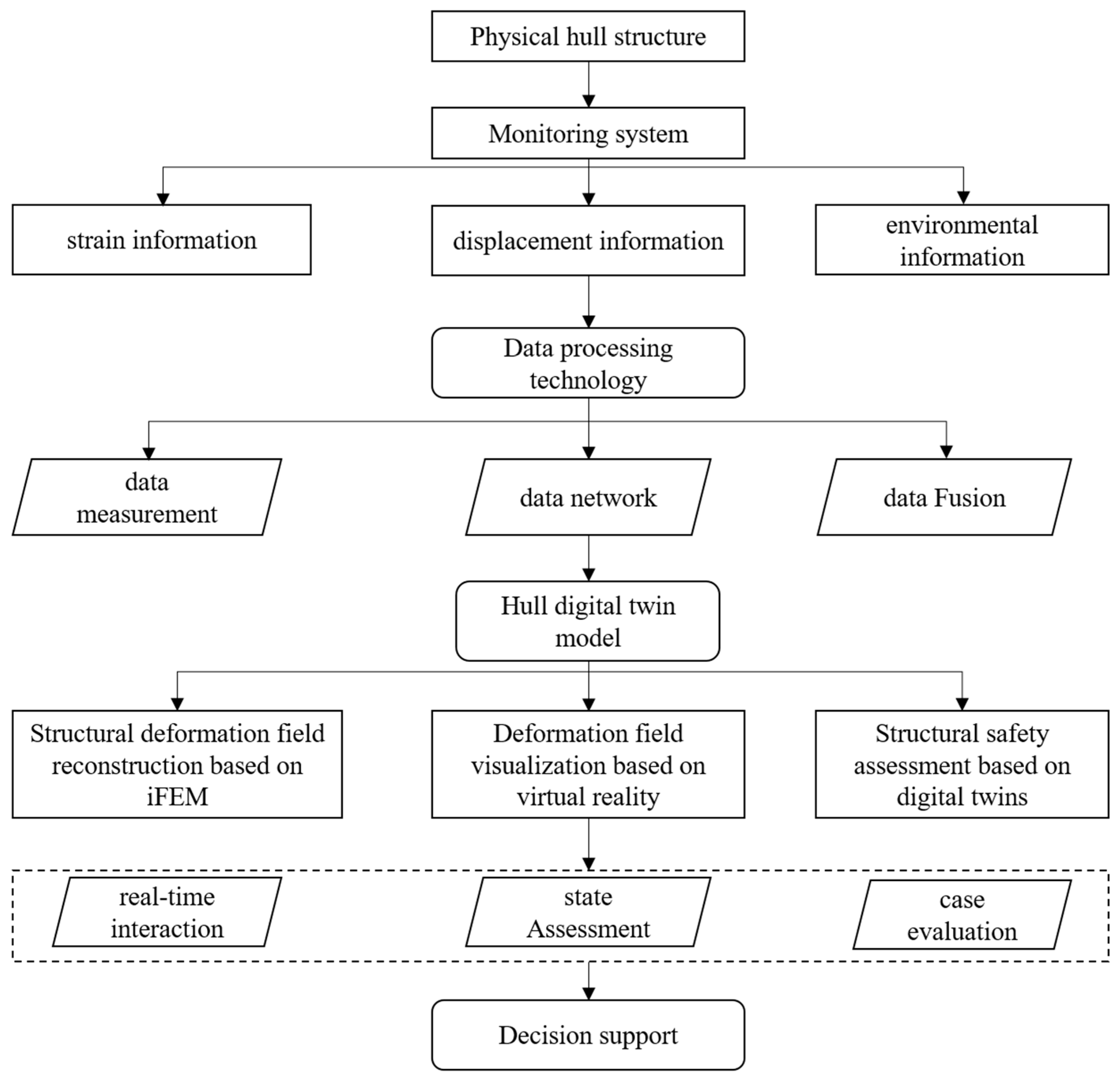
2.1. Real-Time Digital Twin of Ship Structure Deformation Field

Digital twins, utilized for the real-time assessment of ship structure deformation fields, require the following basic elements: a fusion of physical measurements and virtual data, a reconstruction of the deformation field, and a virtual–real fusion visual interactive platform. These components can interlink and bolster a variety of complementary functions, such as data analysis, monitoring, and decision-making. The execution of all analyses, simulations, and visualizations should occur in real time to provide a robust framework for the rapid evaluation of the ship structure’s deformation field. This novel digital twin system harbors the potential to aid operators’ decision-making processes concerning hull structure safety assessments. It focuses on the deterministic identification of the structural deformation state under specified loads, as opposed to statistical values predicated on marine environmental factors or labor-intensive numerical simulation computations. The system can proffer more granular information on the entire field of the ship structure, thereby mitigating the risk of structural failure induced by the excessive operation of the vessel. As current circumstances dictate, extant digital services are not without their flaws [37]. In the future, the completed system should incorporate assessments of potential large deformations of ship structures under severe sea conditions.
The composition of the digital twin platform for the real-time assessment of ship structure deformation fields is depicted in Figure 1. It encompasses a physical scene and strain data measurement module, an iFEM-based deformation field reconstruction module, a virtual scene construction and data fusion module, a deformation field visualization module, and a digital twin integration platform. The bottom layer of the deformation field reconstruction module integrates the iFEM algorithm to derive global field deformation information about the structure via measured strain data. The virtual sensor measurement module prompts the model within the virtual scene to mimic motion responses consistent with the physical scene, using displacement data derived from the loading device in the physical scene. The deformation field virtual visualization module offers users immersive interactive functionalities within virtual scenes to facilitate the exploration of structural mechanical properties. The digital twin platform amalgamates these diverse functional modules, thereby constructing a digital twin software system for the real-time assessment of ship structural deformation fields through its deployment.

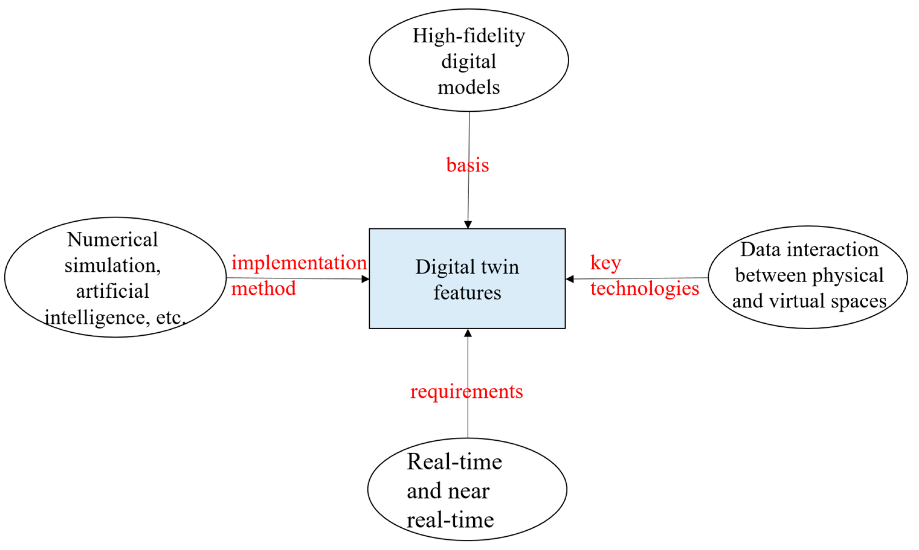
2.2. Digital Twin Architecture

Assani et al. [38] described the application of digital twins within the sphere of marine engineering. Upon a perusal of the extant literature, it can be observed that digital twins have varying degrees of integration in imitating physical objects. The first layer is referred to as the digital model, encompassing the digital simulation of the physical entity where the communication between the digital and physical object is wholly manual. The second layer, also known as the digital shadow, ensures the one-way flow of data wherein alterations in the physical model’s state are mirrored within the digital copy. The third layer, known as the digital twin, exhibits seamless bi-directional information transmission between the physical and digital objects. The theoretical concept of the digital twin encompasses procuring load data and hull response readings through environmental monitoring to formulate a simulation model. The intersection of virtuality and reality facilitates the conversion of environmental monitoring outcomes into structural stress results, with the digital model guiding and forecasting for the physical model. As illustrated in Figure 2, the characteristics of digital twins can be described as follows:
(1)
The transition from physical space to virtual space rests on the premise that the digital model possesses high fidelity.
(2)
The implementation approach involves numerical simulation technology and artificial intelligence.
(3)
The key technology lies in facilitating data interaction between physical and virtual spaces.
(4)
The implementation requirement is to meet real-time performance as much as possible.
For hull structures, traditional beam theory coupled with finite element and other technologies have offered varying degrees of fidelity in virtual models and numerical simulation results, aligning with the first two characteristics referenced above. The key to realizing the digital twins of ship hull structures currently lies in enhancing the fidelity of virtual models and simulation results, and ensuring rapid responses. Though monitoring the external environment of hull structures is still in its infancy, stress monitoring is relatively mature. Consequently, strain measurements can serve as the data source for the digital twin system dedicated to ship structure safety monitoring. Given the impracticality of installing strain sensors at all points in the ship structure, particularly within narrow and enclosed spaces, utilizing limited strain measurement locations to procure the global field information of the structure poses a significant technical challenge. Additionally, the finer the numerical model, the higher the computational cost, which contradicts the real-time nature of digital twins. Hence, resolving the swift response within the digital twin platform remains an important issue. In this research, the conceptual implementation of the digital twin for a ship hull structure safety assessment (Figure 3) envisages using partial stress monitoring points to effectuate the deformation field reconstruction, supplemented with displacement monitoring data in the physical environment. Such data are incorporated into the construction and simulation technology of the digital hull structure model, and the structural state of the ship’s global field is obtained through an efficient computation of the deformation field reconstruction. In the meanwhile, relevant measured data and reconstruction results are relayed back to engineering and experimental designers via virtual reality technology.
Digital twin epitomizes the cutting-edge evolution in implementing digital modeling, simulation, and industrial internet of things (IoT) technology, encompassing all digital models of the physical system to simulate, predict, and assess key activities interrelated with physical measurement data. The content of the digital twin is organized here as the embodiment of the physical entity, interconnectedness of states and data harvested from the entity, and simulation or scrutiny of behavior. A digital twin includes all entities and virtual models shared in the simulation. Sensor measurement data collected from the system serve in the analysis and simulation of the structural mechanical behavior. The digital twin developed in this research facilitates a bidirectional flow of data information between the actual hull structure and its virtual model. Additionally, for a digital twin platform of high-fidelity simulation models across multiple domains, it is prudent to adopt a phased progression in development. Functional modules are independently developed and then associated with the digital twin platform to strike the necessary equilibrium between fidelity and simplification.

2.3. Inverse Finite Element Formulation for Shells

The real-time, rapid, and accurate acquisition of structural state information is crucial for early warning mechanisms and bolstering ship safety. Most SHM methods do not take into account the structure’s topology and boundary conditions. The iFEM reconstructs the overall displacement field of the structure in real time from strain data gathered from a network of sensors stationed at various points on the structure. Unlike other developed SHM systems, the iFEM method possesses broad applicability to intricate structures influenced by complex boundary conditions in real time [22]. Given that the strain measurements represent the sole input in the iFEM formulation and the constructed strain-displacement relationship does not involve the structure’s material properties and load information, there is no requirement for prior knowledge of material characteristics and load information, making it well-suited for complex structures. The four-node quadrilateral inverse-shell (iQS4) element formulation is established under the assumption of Mindlin’s first-order plate theory. Considering the practical application in marine structures, the measured strain data in this study serve as the input for the iFEM algorithm, with the structure’s deformation field as the output data.

2.3.1. Quadrilateral Inverse-Shell Element

This section employs the iQS4 element to demonstrate the derivation process of the iFEM formula. As depicted in Figure 4a, the iQS4 element, global coordinate system XYZ, and local coordinate system xyz are illustrated. The origin of the xyz system is located at the centroid of the element’s middle surface quadrilateral. Nestled at the centroid of the middle surface quadrilateral of the element and furnished with six degrees-of-freedom (DOF) per node, as highlighted in Figure 4b, the iQS4 element encompasses translations u i ,   v i ,   w i in addition to rotations θ x i ,   θ y i ,   θ z i . The theoretical strain of the structural element is divided into plane strain e ( u e ) , bending curvature k ( u e ) , and transverse shear strain g ( u e ) , where u e symbolizes the displacement exhibited by the four nodes. The formulation of the iQS4 element is actualized initially by composing the membrane and bending curvature matrices separately, ultimately amalgamating them for exportation. The relevant calculations of the iQS4 are procured relying on Mindlin’s plate theory, considering the influence of shear deformation. According to the assumptions of Mindlin’s first-order plate theory, the relevant derivatives of the three components of the displacement vector are calculated. Subsequently, the strain-displacement relationship of linear elastic theory is deduced as follows:
e ( u e ) + z k ( u e ) = B m u e + z B k u e = ( ε x x ε y y ε z z ) T g ( u e ) = B s u e = ( γ x z γ y z ) T
where u e = [ u 1 e   u 2 e   u 3 e   u 4 e ] , u i e = [ u i   v i   w i   θ x i   θ y i   θ z i ] T   with   ( i = 1 ,   2 ,   3 ,   4 ) , and B m is a matrix that stands for the derivatives of the shape functions associated with the membrane behavior. Conversely, B k ,   B s matrices manifest the corresponding derivatives of shape functions designed to delineate the bending behavior of the element.

2.3.2. Input Data from In Situ Strain Sensors

The input for the iFEM is the measured strains at the center points on the top and bottom surfaces of each inverse element, as illustrated in Figure 5. Commonly used strain sensors incorporate strain rosettes or FBG sensor networks. The distinct attributes of an FBG system include its lightweight nature, swift operation, immunity to electromagnetic interference, and a lack of necessity for recalibration post installation. Tessler and Spangler (2005) pointed out that reference plane strains e i ε and curvatures k i ε could be calculated utilizing measured surface strains [39]. In Equations (2) and (3), ε x x + ,   ε y y + ,   γ x y + denotes the measured strain on the upper surface of the element, ε x x ,   ε y y ,   γ x y represent the measured strain on the lower surface of the element, and h is the distance from the middle surface to the surface. Transverse shear strain g i ε cannot be measured directly through strain rosette sensors. However, in the context of plate and shell structures, the value of transverse shear strain is much smaller those of plane strain and bending curvature, thereby rendering the influence of transverse shear strain negligible in the iFEM formulation.
e i ε = 1 2 ( ( ε x x + ε y y + γ x y + ) + ( ε x x ε y y γ x y ) ) i   with   ( i = 1 , , n )
k i ε = 1 2 h ( ( ε x x + ε y y + γ x y + ) ( ε x x ε y y γ x y ) ) i   with   ( i = 1 , , n )

2.3.3. Weighted Least-Squares Function

At the core of the iFEM lies the construction of a least-squares function ϕ e ( u e ) between the measured strains of an element and the theoretical strains. By considering the membrane, bending, and transverse shear deformation of the element, the least-squares function is minimized with respect to the nodal displacements using the variational principle. Subsequently, an estimated value for the node displacement is procured and deemed reflective of the measured displacement.
ϕ e ( u e ) = w e e ( u e ) e ε 2 + w k k ( u e ) k ε 2 + w g g ( u e ) g ε 2
In Equation (4), w e ,   w k ,   w g are weight coefficients. The correct use of the weighting constant is especially critical for problems involving a relatively small number of strain measurement points. Setting the weighting constant at 1 is recommended when the element possesses a corresponding strain measurement value. The square norm depicted in Equation (4) can be rephrased in the context of a normalized Euclidean norm as follows:
e ( u e ) e ε 2 = 1 n A e i = 1 n ( e ( u e ) i e i ε ) 2 d x d y k ( u e ) k ε 2 = ( 2 t ) 2 n A e i = 1 n ( k ( u e ) i k i ε ) 2 d x d y g ( u e ) g ε 2 = 1 n A e i = 1 n ( g ( u e ) i g i ε ) 2 d x d y
In the formula, A e is the area of the element. For inverse elements without strain sensors, the weighting constant is set to 10−5. These weighting constants guarantee satisfactory regularization of Equation (4), even under circumstances where the iFEM model presents scant measurement strain data. This allows for necessary interpolation linkages between inverse-shell elements equipped with strain rosettes. Nonetheless, augmenting the quantity of elements for strain-free measurements has the potential to impair the precision of the deformation field reconstruction. With these assumptions, the least-squares function is minimized using the variational principle, i.e., through the extraction of partial derivatives relative to nodal displacements:
ϕ e ( u e ) u e = k e u e - f e = 0  
where k e ,   f e are the inverse stiffness matrix and load column matrix of the element, respectively. The overall displacement of the structure can be calculated from both the overall inverse stiffness matrix and the corresponding inverse load column matrix. Once the local matrix equations are defined, the element contributions to the global linear equation system of the discretized structure can be obtained as follows:
KU = F  
where K is correlated with the measured strain value, U embodies the global nodal displacement vector, and F represents a global function of the measured strain value.

2.4. Visualization and Visual Interaction

The use of VR technology in the evaluation of engineering analysis results has attracted increasing attention [40]. Some existing shared formats can indeed enhance the exchangeability of deformation field data in VR scenarios. However, they are still relatively inefficient. Therefore, the concept of a new practical shareable neutral data architecture is proposed for the effective sharing of multidisciplinary data in collaborative environments. The most critical requirements are summarized below:
(1)
Improve access to data sources and automation level.
(2)
Provide higher data processing efficiency and facilitate verification by design and engineering personnel.
(3)
Enhance the immersive exploration of data results.
(4)
Enhance the interactivity of simulation results.
(5)
Traceability and consistency of data result conversion.
This study attempts to propose a VR-based visualization postprocessing system for the virtual visualization of strain field data, thereby enhancing the attention of engineering designers and managers to the structural change results. Among them, the developed workflows range from reading raw data to displaying visualizations in a virtual environment (VE). Hence, a virtual visualization framework was established, as shown in Figure 6. The virtual visualization system consists of three modules, which are a discrete mesh model reconstruction module, deformation field data processing module, and virtual interaction module. Through customized data interfaces between different modules, data interaction and management during system integration can be realized. The discrete mesh model reconstruction module primarily completes the reconstruction of the target structure in the virtual scene, laying the foundation for the visualization of the deformation field cloud diagram. The deformation field data processing module mainly completes readings and node assignments for the deformation field data obtained by the iFEM algorithm. The virtual interaction module renders and interacts with the deformation field and observes and evaluates the structure through various interactive methods such as segmentation, rotation, slicing, and extraction.
The process of visualizing the discrete mesh model and deformation field data involves nodes, elements, vertex sequences, normal sequences, edge sequences, and texture sequences. Shareable models must minimize files while retaining necessary information. Since the Unity 3D platform does not support quad-mesh rendering, the meshing and reorganization algorithms are also embedded. Delaunay triangulation (DT) is the most common unstructured triangulation method in many applications [41], which maximizes the minimum angle of any triangle [42]. For large-scale models, the subdivision and reorganization algorithm was designed in parallel, and Python’s multi-processing module is used to call multiple processes to achieve full utilization of system resources. In the division, elements are evenly distributed among different processes, and their array intervals are calculated. During the reorganization process, data blocks are evenly distributed to different processes for sub-model reorganization, where each process reads the shared data without writing.

3. Case Studies for Real-Time Digital Twin

3.1. Application Objects and Test Preparation

This paper targeted a stiffened plate structure of an actual hull, aiming to validate the reconstruction algorithm, deformation field visualization, and digital twin platform. The employed material was Q235 steel. The stiffened plate structure contained two types of stiffeners: T-shaped bar and flat steel, as represented by a geometric schematic in Figure 7. The main geometric parameters of the stiffened plate structure test object are depicted in Table 1 and Table 2.
Figure 8 illustrates the configuration of the strain rosettes and displacement sensors, with displacement meters (w1–w6) placed in areas of significant vertical displacement. Strain gauges were located in areas of high stress levels, incorporating triaxial strain rosettes (T1–T24) at the center of the plate grid, and uniaxial strain gauges (S1–S8) at the mid-span of the reinforced rib and T-profile web. Figure 9 showcases the stiffened plate structure test scheme, primarily comprising longitudinal reaction frames, crossbeams, and hydraulic cylinders. The reaction frame was fixed to the ground, while the hydraulic cylinder transferred the load to the crossbeam, thereby applying axial compression load onto the stiffened plate. Displacement sensors measure the stroke of the hydraulic cylinder. The surface load imposed on the stiffened plate structure was facilitated through the use of sandbags.

3.2. Ship Structural Mechanics Test Digital Twin

Considering the increasing importance of digital twins within the ship industry, a digital twin data integration method adaptable to different data classifications is proposed, supporting data exchange and interoperability between various functional modules. Within the context of content, a framework was established for both physical scene representation and status alongside a methodology for simulating the mechanical behavior of the target structure. Digital twin data are arranged into independent databases, accompanied by textual descriptions outlining their purpose and attributes. Through this modular approach, the independence of distinct data resources is preserved while enhancing the data exchange. The digital twin framework, developed based on these principles, was applied to a case study examining a hull structural mechanic tests, aiming to serve as a starting point for more complex future applications. Digital twin data were associated with deformation field reconstruction algorithms and virtual visualization algorithms, developed within a proprietary platform. These were employed for monitoring and controlling the mechanical tests of the target structure model, thus offering a superior degree of service maturity and a wider spectrum of data information in comparison to mere online monitoring tools.
In accordance with the categories expounded upon in Section 2.2, digital twin content was divided into four groups: physical models, sensor monitoring, virtual scenes, and behavior models. Data patterns were discerned and mapped using referencing tags retained in an array of databases. Physical models and virtual scenes were linked and mapped through 3D models, sensors, location coordinates, and identification tags in the hull structural mechanics test scene, as shown in Figure 10. The 3D models in the virtual scene exhibited comprehensive detailing (e.g., side and bottom), while the overall motion response was monitored through the assimilation of collision and displacement data within the physical scene. The behavior model was mainly realized through deformation field models, constructed by the iFEM algorithm. An overview of the digital twin pattern is presented in Figure 11.

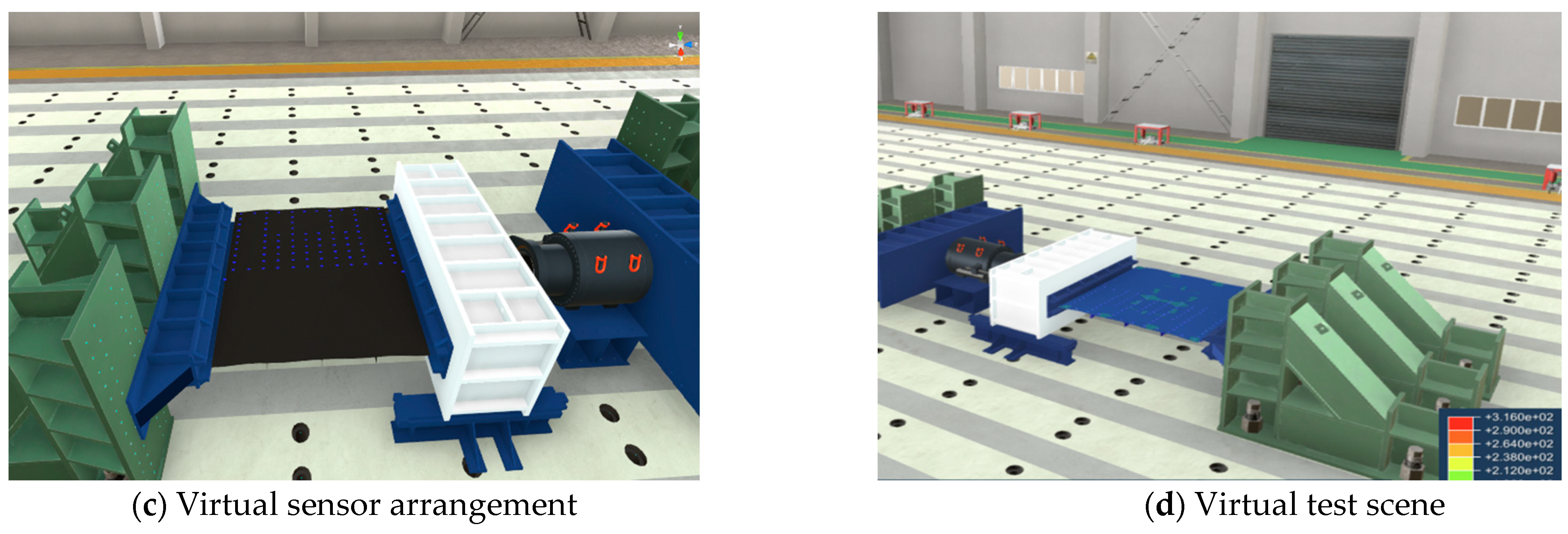
3.3. Visualization and Interaction

The virtual visualization system architecture adopted a multi-module design method and independent interfaces for data transmission between modules such as mesh segmentation and reorganization, data visualization, visualization and interaction functions, which not only ensured the relative independence and functional scalability of each module, but also standardized data communication between systems. This study adopted the divide-and-conquer approach [43] to reconstruct the finite element mesh in the virtual environment. Figure 12 shows the model reconstruction and rendering process based on point arrays in the virtual environment. The node index, node coordinates, element index and node connection order of the mesh were extracted, and the node array was drawn in the virtual visualization space. Through the mesh index, the quadrilateral elements were spatially divided to construct subsets, a Delaunay triangle subgrid was constructed in each subset, and the subgrids were merged recursively. The mesh reconstruction prioritizes the original triangular mesh and construction order in the finite element data to avoid local shape distortion. By mapping the numerical solutions of physical quantities on nodes into the RGB color space [44], a color cloud image for the deformation data visualization was constructed. The virtual visualization system was built and released based on Unity 3D 2019 software and was developed using C# and Python, which run on the Microsoft Windows operating system. This study used a surround-screen virtual test environment provided by the Virtual Reality Laboratory of Ship Digital Design of Shanghai Jiao Tong University in China.
Overall, in the visualization strategy of the virtual visualization system, the mesh nodes were loaded first. Then, the finite element mesh was reconstructed according to the connection sequence of each element. Finally, the node solutions and element solutions were extracted from the deformation filed database for assignment to realize the model rendering and visualization. It should be emphasized that the rendering of the model was interpolated through the color of the triangle patch nodes, and finally, the rendering of the entire finite element model was achieved. For the visual interaction module, the aim was to facilitate the exchange of data between humans and machines. The operation methods included model scaling, perspective slicing, rotation, cropping, and mesh hiding, which can be carried out by mouse, keyboard, or VR gamepad. As for the deformation file results, they can be checked using a handheld cutter or clipped using a virtual cube. The physical model test application scenario is shown in Figure 13.

3.4. Real-Time Digital Twin Platform

Based on the Unity3D platform, a graphical interface for the real-time digital twin of ship structural mechanics is provided to users, thereby enabling remote data access and control over physical tests. The interface displays four elements: the central 3D scene, the sensor data information window on the left, the 3D deformation field visualization graphic window, the physical scene video window on the right, and the control panel at the top (Figure 14). The 3D visualization is nearly synchronous with the physical scene test process, exhibiting real-time displays and facilitating six DOFs in rotation and scaling operations. The most basic function of the digital twin involves the supervision and control of the experiment. The interactive interface provides two monitoring methods: data and video. Cameras are placed to allow users to remotely view the physical test scene. The displacement data of the loading device provides users with the most direct load information, frequently employed to authenticate the functionality of the propulsion system and the loading state of the model, and to corroborate the synchronicity of the virtual assembly model with the physical model during the test. For monitoring structural mechanical behaviors, real-time deformation reconstruction results and comparisons with measured displacement data are provided through the iFEM algorithm. The left side of Figure 14 shows output strain measurement point data, a deformation reconstruction, and a comparison with measured data. This feature proves particularly useful during experimentation, in facilitating debugging, and during testing of the experimental setup.

4. Discussion

Drawing on our experience, promoting data exchanges and interoperability has facilitated the construction of the synchronized motion response of the virtual assembly scene relative to the physical testing process. Ensuring the effective communication of assumptions among test engineers, whether through detailed software documentation or verbal directives, enables operators to respond adeptly and diminishes the likelihood of test failures. A significant theme for subsequent research involves exploring methods for executing more complex application scenarios within the digital twin framework, with an ultimate aim to expand its applicability to a broader digital architecture. However, it is worth noting that our current research methodology lacks the capability to solve the reconstruction problem associated with nonlinear large deformations of the structure. Currently, there are two potential solutions to address this issue. The first solution involves using a method similar to Newton’s iteration, which takes into account the nonlinear problems arising from geometry and materials. However, this method may result in extended response times during the reconstruction process. The second solution proposes correcting the reconstruction results using a fast-order reduction calculation method. This approach effectively ensures a rapid response during the reconstruction process.

5. Conclusions

Powerful online monitoring technology serves as a pivotal catalyst for remote control centers, particularly when integrated with dynamic perception algorithms. Practical case studies demonstrate the potential of digital twins in augmenting the monitoring of ship structural mechanic characteristics. The utilization of immersive visualization simplifies the conveyance of the mechanical behavior and state of a structure, superseding traditional methods such as the exhibition of logs and diagrams or the triggering of alarms. The responsive interaction employed in this paper was actualized through a high-frequency data exchange communication system interfacing with the physical setup. A modular methodology was employed to link the deformation field monitoring system to the digital twin. The iFEM approach was used to acquire real-time, global field deformation information of the target structure, eschewing reliance solely on independent data from key discrete measurement points. On one hand, the integration of the iFEM algorithm facilitates rapid responses to strain data, offering more flexibility compared to traditional time-consuming numerical simulations and enhancing the capabilities of the digital twin as a unified integrated system. On the other hand, the proposed immersive virtual visualization interaction scheme revolutionizes the exploration of structural mechanical behaviors and enhances the workflow of virtual reality-supported decision making. Unforeseen interactions may surface during the operation of distributed subsystems.

Author Contributions

Conceptualization, C.L.; Methodology, C.L. and D.W.; Software, P.W. and Z.J.; Validation, C.L. and D.W.; Investigation, Z.J.; Data curation, P.W. and Z.J.; Writing—original draft, P.W.; Writing—review & editing, C.L. and D.W.; Visualization, Z.J.; Supervision, Z.J. All authors have read and agreed to the published version of the manuscript.

Funding

This paper was supported by the project of National Natural Science Foundation of China (Grant No. U2241266), Innovative Research Foundation of Ship General Performance (26822212), Fundamental Research Funds for the Central Universities, and The National Key Research and Development Program of China (2022YFB3404800).

Data Availability Statement

Data are contained within the article.

Conflicts of Interest

The authors declare no conflict of interest.

References

  1. Fonseca, Í.A.; Gaspar, H.M. Challenges when creating a cohesive digital twin ship: A data modelling perspective. Ship Technol. Res. 2021, 68, 70–83. [Google Scholar] [CrossRef]
  2. Momdoro, A.; Soliman, M.; Frangopol, D.M. Prediction of structural response of naval vessels based on available structural health monitoring data. Ocean. Eng. 2016, 125, 295–307. [Google Scholar] [CrossRef]
  3. Johnson, N.R.; Lynch, J.P.; Collette, M.D. Response and fatigue assessment of high speed aluminium hulls using short-term wireless hull monitoring. Struct. Infrastruct. Eng. 2018, 14, 634–651. [Google Scholar] [CrossRef]
  4. Jo, J.; Jo, B.; Khan, R.M.A.; Kim, J. A cloud computing-based damage prevention system for marine structures during berthing. Ocean. Eng. 2019, 180, 23–28. [Google Scholar] [CrossRef]
  5. Chung, W.C.; Pestana, G.R.; Kim, M. Structural health monitoring for TLP-FOWT (floating offshore wind turbine) tendon using sensors. Appl. Ocean. Res. 2021, 113, 102740. [Google Scholar] [CrossRef]
  6. Mieloszyk, M.; Majewska, K.; Ostachowicz, W. Application of embedded fiber Bragg grating sensors for structural health monitoring of complex composite structures for marine applications. Mar. Struct. 2021, 76, 102903. [Google Scholar] [CrossRef]
  7. Karvelis, P.; Georgoulas, G.; Kappatos, V.; Stylios, C. Deep machine learning for structural health monitoring on ship hulls using acoustic emission method. Ships Offshore Struct. 2021, 16, 440–448. [Google Scholar] [CrossRef]
  8. Silionis, N.E.; Anyfantis, K.N. Static strain-based identification of extensive damages in thin-walled structures. Struct. Health Monit. 2022, 21, 2026–2047. [Google Scholar] [CrossRef]
  9. Arrichiello, V.; Gualeni, P. Systems engineering and digital twin: A vision for the future of cruise ships design, production and operations. Int. J. Interact. Des. Manuf. 2020, 14, 115–122. [Google Scholar] [CrossRef]
  10. Ibrion, M.; Paltrinieri, N.; Nejad, A.R. Learning from failures in cruise ship industry: The blackout of Viking Sky in Hustadvika, Norway. Eng. Fail. Anal. 2021, 125, 105355. [Google Scholar] [CrossRef]
  11. Woolley, A.; Whitehouse, T. A modelling and simulation framework to assess integrated survivability of naval platforms in high threat environments. Ocean. Eng. 2022, 257, 111479. [Google Scholar] [CrossRef]
  12. Mauro, F.; Kana, A.A. Digital twin for ship life-cycle: A critical systematic review. Ocean. Eng. 2022, 269, 113479. [Google Scholar] [CrossRef]
  13. Ludvigsen, K.B.; Smogeli, Ø. Digital Twins for Blue Denmark. Marine Cybernetics Advisory; DNV GL Maritime: Hamburg, Germany, 2018. [Google Scholar]
  14. Coraddu, A.; Oneto, L.; Baldi, F.; Cipollini, F.; Atlar, M.; Savio, S. Data driven ship digital twin for estimating the speed loss caused by the marine fouling. Ocean. Eng. 2019, 186, 106063. [Google Scholar] [CrossRef]
  15. Tofte, B.L.; Vennemann, O.; Mitchell, F.; Millington, N.; McGuire, L. How digital technology and standardisation can improve offshore operations. In Proceedings of the Offshore Technology Conference, Offshore Technology Conference, Houston, TX, USA, 6–9 May 2019. [Google Scholar]
  16. Bernasconi, A.; Kharshiduzzaman, M.; Anodio, L.F.; Bordegoni, M.; Re, G.M.; Braghin, F.; Comolli, L. Development of a monitoring system for crack growth in bonded single-lap joints based on the strain field and visualization by augmented reality. J. Adhes. 2014, 90, 496–510. [Google Scholar] [CrossRef]
  17. Schirmann, M.; Collette, M.; Gose, J. Ship motion and fatigue damage estimation via a digital twin. In Proceedings of the 6th International Symposium on Life-Cycle Civil Engineering (IALCCE), Ghent, Belgium, 28–31 October 2018; Caspeele, R., Taerwe, L., Frangopol, D.M., Eds.; CRC Press: Boca Raton, FL, USA, 2018; pp. 2075–2082. [Google Scholar]
  18. Lloyds Register. ShipRight Ship Event Analysis; Lloyds Register: London, UK, 2004. [Google Scholar]
  19. American Bureau of Shipping. American Bureau of Shipping Guide for Hull Condition Monitoring Systems; American Bureau of Shipping: Houston, TX, USA, 1995. [Google Scholar]
  20. Majewska, K.; Mieloszyk, M.; Ostachowicz, W.; Król, A. Experimental method of strain/stress measurements on tall sailing ships using Fibre Bragg Grating sensors. Appl. Ocean. Res. 2014, 47, 270–283. [Google Scholar] [CrossRef]
  21. Tessler, A. A Variational Principle for Reconstruction of Elastic Deformations in Shear Deformable Plates and Shells; National Aeronautics and Space Administration, Langley Research Center: Hampto, VA, USA, 2003. [Google Scholar]
  22. Tessler, A.; Spangler, J.L. Inverse FEM for full-field reconstruction of elastic deformations in shear deformable plates and shells. In Proceedings of the 2nd European Workshop on Structural Health Monitoring, Munich, Germany, 7–9 July 2004. [Google Scholar]
  23. Gherlone, M.; Cerracchio, P.; Mattone, M.; Di Sciuva, M.; Tessler, A. Shape sensing of 3D frame structures using an inverse finite element method. Int. J. Solids Struct. 2012, 49, 3100–3112. [Google Scholar] [CrossRef]
  24. Gherlone, M.; Cerracchio, P.; Mattone, M.; Di Sciuva, M.; Tessler, A. An inverse finite element method for beam shape sensing: Theoretical framework and experimental validation. Smart Mater. Struct. 2014, 23, 045027. [Google Scholar] [CrossRef]
  25. Wang, Y.; Nnaji, B.O. Document-driven design for distributed CAD services in service-oriented architecture. J. Comput. Inf. Sci. Eng. 2006, 6, 127–138. [Google Scholar] [CrossRef]
  26. Freeman, I.; Salmon, J.; Coburn, J. A bi-directional interface for improved interaction with engineering models in virtual reality design reviews. Int. J. Interact. Des. Manuf. 2018, 12, 549–560. [Google Scholar] [CrossRef]
  27. Kefal, A.; Oterkus, E. Displacement and stress monitoring of a chemical tanker based on inverse finite element method. Ocean. Eng. 2016, 112, 33–46. [Google Scholar] [CrossRef]
  28. CEI—Creators of Ensight Visualization Software. 2011. Available online: http://www.ensight.com/ (accessed on 29 November 2011).
  29. VTFx Format—Ceetron. 2011. Available online: http://www.ceetron.com/vtfx format.aspx (accessed on 29 November 2011).
  30. Song, I.-H.; Yang, J.; Jo, H.; Choi, S. Development of a lightweight CAE middleware for CAE data exchange. Int. J. Comput. Integ M. 2001, 22, 823–835. [Google Scholar] [CrossRef]
  31. Cho, S.W.; Kim, S.W.; Park, J.-P.; Yang, S.W.; Choi, Y. Engineering collaboration framework with CAE analysis data. Int. J. Precis. Eng. Man. 2011, 12, 635–641. [Google Scholar] [CrossRef]
  32. Liu, Q.; Li, J.; Liu, J. ParaView visualization of Abaqus output on the mechanical deformation of complex microstructures. Comput. Geosci. 2017, 99, 135–144. [Google Scholar] [CrossRef]
  33. Hambli, R.; Chamekh, A.; Salah HB, H. Real-time deformation of structure using finite element and neural networks in virtual reality applications. Finite Elem. Anal. Des. 2006, 42, 985–991. [Google Scholar] [CrossRef]
  34. Connell, M.; Tullberg, O. A framework for immersive FEM visualization using transparent object communication in a distributed network environment. Adv. Eng. Softw. 2002, 33, 453–459. [Google Scholar] [CrossRef]
  35. Tzong-Ming, C.; Tu, T.H. A fast parametric deformation mechanism for virtual reality applications. Comput. Ind. En. 2009, 57, 520–538. [Google Scholar] [CrossRef]
  36. Ryken, M.J.; Vance, J.M. Applying virtual reality techniques to the interactive stress analysis of a tractor lift arm. Finite Elem. Anal. Des. 2000, 35, 141–155. [Google Scholar] [CrossRef]
  37. Lee, J.H.; Nam, Y.S.; Kim, Y.; Liu, Y.; Lee, J.; Yang, H. Real-time digital twin for ship operation in waves. Ocean. Eng. 2022, 266, 112867. [Google Scholar] [CrossRef]
  38. Assani, N.; Matić, P.; Katalinić, M. Ship’s digital twin—A review of modelling challenges and applications. Appl. Sci. 2022, 12, 6039. [Google Scholar] [CrossRef]
  39. Tessler, A.; Spangler, J.L. A least-squares variational method for full-field reconstruction of elastic deformations in shear-deformable plates and shells. Comput. Methods Appl. Mech. Eng. 2005, 194, 327–339. [Google Scholar] [CrossRef]
  40. Maleshkov, S.; Chotrov, D. Post-processing of engineering analysis results for visualization in VR system. Int. J. Comput. Sci. Issues 2013, 10, 258–263. [Google Scholar]
  41. Rodriguez, I. Dynamic Occlusion Culling Using Octrees with Unity for Virtual Reality; The University of Texas at San Antonio: San Antonio, TX, USA, 2017. [Google Scholar]
  42. Chen, L.; Xu, J. Optimal delaunay triangulations. J. Comput. Math. 2004, 22, 299–308. [Google Scholar]
  43. Woo, Y. Abstraction of mid-surfaces from solid models of thin-walled parts: A divide-and-conquer approach. Comput-Aided Des. 2014, 47, 1–11. [Google Scholar] [CrossRef]
  44. Yeh, T.P.; Vance, J.M. Applying virtual reality techniques to sensitivity-based structural shape design. J. Mech. Des. 1998, 120, 612–619. [Google Scholar] [CrossRef]
Figure 1. Overall process of real-time digital twin.
Jmse 12 00257 g001
Figure 2. Characteristics of the digital twin approach.
Jmse 12 00257 g002
Figure 3. Real-time digital twin technology flow chart for hull structure safety assessment.
Jmse 12 00257 g003
Figure 4. Four-node inverse-shell element. (a) iQS4 element showing global and local coordinate systems; (b) Nodal DOFs in the local coordinate system xyz.
Jmse 12 00257 g004
Figure 5. Strain rosettes instrumented on the top and bottom of iQS4 elements.
Jmse 12 00257 g005
Figure 6. Deformation field virtual visualization implementation process.
Jmse 12 00257 g006
Figure 7. Schematic of 3D model of stiffened plate.
Jmse 12 00257 g007
Figure 8. Stiffened plate model strain gauge and displacement gauge layout diagram.
Jmse 12 00257 g008
Figure 9. Loading scheme of the test model.
Jmse 12 00257 g009
Figure 10. The construction process of digital twin scenarios.
Jmse 12 00257 g010aJmse 12 00257 g010b
Figure 11. Data transfer of digital twin models.
Jmse 12 00257 g011
Figure 12. Model reconstruction and rendering based on point arrays.
Jmse 12 00257 g012
Figure 13. Deformation field cloud diagram.
Jmse 12 00257 g013
Figure 14. Real-time digital twin platform for ship structure mechanic testing.
Jmse 12 00257 g014
Table 1. Main scale parameters of stiffened plate model (unit mm).
LengthWidthPanel LengthPanel Width
400416.710069.4
Table 2. Stiffened plate model structural parameters (unit mm).
Plate ThicknessNumber of T ProfilesNumber of Flat BarsT Profile Parameters
hw × tw/bf × tf
Flat Steel Parameters
hw × tw
61422 × 6/17 × 610 × 6
Disclaimer/Publisher’s Note: The statements, opinions and data contained in all publications are solely those of the individual author(s) and contributor(s) and not of MDPI and/or the editor(s). MDPI and/or the editor(s) disclaim responsibility for any injury to people or property resulting from any ideas, methods, instructions or products referred to in the content.

