Article

Deep Water Subsea Energy Storage, Lessons Learned from the Offshore Oil and Gas Industry

1
Subsea7, 4033 Stavanger, Norway
2
Department of Energy and Petroleum Engineering, University of Stavanger, 4021 Stavanger, Norway
3
Department of Mechanical Engineering, Massachusetts Institute of Technology, Cambridge, MA 02139, USA
*
Author to whom correspondence should be addressed.
J. Mar. Sci. Eng. 2024, 12(12), 2288; https://doi.org/10.3390/jmse12122288
Submission received: 22 November 2024 / Revised: 6 December 2024 / Accepted: 10 December 2024 / Published: 12 December 2024

Abstract

:
In a future where a large portion of power will be supplied by highly intermittent sources such as solar- and wind-power, energy storage will form a crucial part of the power mix ensuring that there is enough flexibility in the system to cope with the intermittency. With further development of pumped storage hydro constrained by the lack of remaining suitable topography, a novel Subsea Pumped Hydro Storage concept has emerged as a promising solution to utilize the ocean space for large-scale energy storage. While previous publications address thermodynamic efficiency limits, there is a notable lack of research on turbine selection, design, and cost estimation based on best practices. This paper presents a comprehensive overview of current state-of-the-art subsea engineering and its significant achievements pioneered by the oil and gas industry. This paper introduces a robust methodological framework for calculating the costs of concrete SPHS tanks, factoring in longevity and best installation practices for structures designed to endure for half a century. The results indicate that with an optimized design, the cost of an SPSH concrete storage tank is approximately $0.15/Wh. This work lays the groundwork for future advancements in SPHS, building on the substantial progress within subsea engineering over recent decades, and marks a significant step towards realizing the potential of this concept in the renewable energy landscape.

1. Introduction

This article is a revised and expanded version of a paper entitled “Lessons from the Offshore Oil and Gas Industry for Hydro-Pneumatic Subsea Energy Storage Concepts”, which was presented at the International Conference of Applied Energy (ICAE), Bochum Germany 2022 [1].
With the introduction of intermittent renewable energy sources and the scaling down of fossil fuel based power supplies, comes the need for an increased energy storage capacity, requiring significant investments [2]. Diverse requirements point towards an array of different energy storage concepts which are likely to be needed to serve different markets as no single storage concept can meet all demands in every location in a cost-efficient way [3].
The majority of the available global energy storage capacity today consists of pumped hydro energy storage (PHS) [4]. Although a mature and proven technology, there is a concern that there are not enough locations with the required topography for new cost-efficient pumped hydro energy storage facilities. Some research has been made towards placing a PHS at the seabed, notably ORES [5], DOGES [6] and STENSEA [7,8], but no commercial plant currently exists. Unlocking the potential to use the ocean as a location for utility-scale energy storage would address the immediate concerns regarding the lack of suitable locations for PHS in addition to providing an option for co-located energy storage for offshore renewables. To develop a commercially feasible product, the current PHS technology needs to be marinized by subsea engineers.
Previous studies relating to offshore energy storage have not always provided formulas which are helpful for rapid quantitative analysis of potential subsea-PHS systems (SPHS) based on current state-of-the-art subsea engineering.
Formulas for calculating energy capacity as a function of water depth are presented in previous publications [5,8]. Formulas for a tank with constant atmospheric pressure, achieved through the use of an umbilical, is provided in [9]. Previous publications by the authors [10,11] provide a more detailed derivation of mathematical equations including thermodynamic considerations.
In terms of economic assessments, there are several publications found in the literature. Cazzaniga, Cicu [6] has performed a cost analysis of an SPHS system based on steel pipes placed on the seabed. A techno economic assessment of the STENSEA concept is provided in [8]. However, the existing technical assessments typically involve certain assumptions and concept limitations. The authors have considered current state-of-the-art subsea oil and gas engineering to develop a quantitative method for calculating the costs of tanks required for large-scale deepwater energy storage. This method is based on best practices within subsea engineering. Costs as a function of energy storage capacity are presented in Section 5.
The first part of this paper presents a justification for, and a description of, a SPHS system. This is followed by a brief review of the state-of-the-art subsea engineering with regards to subsea control systems, installation methods, trawl protection and structural design. The methodology for the design of tanks for energy storage utilization that employ current best practices found in the oil and gas industry is then reviewed followed by results, discussion and conclusions.

2. System Description

2.1. Subsea Energy Storage

The ocean has tremendous potential to provide a location for low emission energy storage, particularly as offshore wind moves into deeper water depths. Co-located energy storage is likely to be a requirement for reducing the curtailment of offshore wind [12], and regulating power export so it is more stable. In addition, co-located energy storage could also facilitate the distribution of power from planned energy hubs in the North Sea [13]. Depending on the contract forms, studies show that a co-located energy storage “behind the meter” [14] can be used by the operators of offshore renewables to diversify and increase their revenue streams by participating in more lucrative markets such as intra-day or day-ahead markets [15]. Both Equinor and Vattenfall has cited increased costs in their decisions to postpone the Trollvind [16] resp Boreas [17] offshore wind parks, and new revenue streams would be good news for operators struggling with increased costs.

2.2. Subsea Energy Storage Concept

The SPHS concept and the thermodynamic efficiencies are presented in [10,11] but a short summary will be given here. Power and fluid flows during charge and discharge are shown in Figure 1. The energy storage is provided by utilizing the pressure differences between the pressure inside a rigid tank, p t a n k , placed at the seabed and the constant hydrostatic pressure in the surrounding ocean, p o c e a n , outside the tank. If the rigid tank is initially filled with gas at pressure p 0 < p o c e a n , the pressure difference can be utilized to create a flow of water into the tank from the ocean. The water entering the tank will compress the gas until the pressure in the tank, p t a n k , is equal to the ocean hydrostatic pressure p o c e a n . By placing a turbine coupled with a generator at the inlet of the tank, the kinetic energy of the flow can be converted into electrical power. Once the pressure in the tank is the same as the hydrostatic pressure, p t a n k = p o c e a n , the energy storage unit is fully discharged. To charge the system, pumps will remove water from the tank restoring the pressure difference such that eventually the pressure in the tank equals the initial pressure, p t a n k = p 0 , and the system is now fully charged. One turbine/generator can be associated with each tank, or a network of modular tanks connected to a central large turbine/generator may be used.

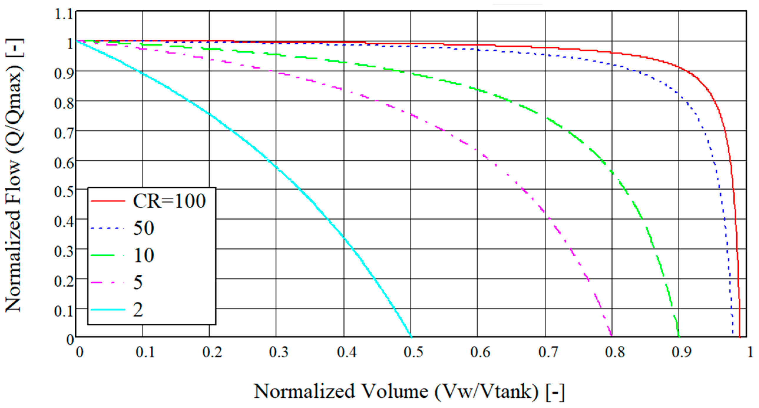
2.2.1. Properties of Subsea Energy Storage in a Rigid Gas Filled Tank

The theoretical energy density, ϵ i s o , of the SPSH concept was derived in [10] and can be calculated using the following formula, assuming an isothermal process:
ϵ i s o = p 0 C R 1 ln C R
where CR is the compression ratio p o c e a n / p 0 , i.e., the pressure before and after water has been filled into the tank. The calculated energy density in (1) is made under the assumption of an isothermal process and any deviation from an isothermal process would reduce the efficiency and energy density of the concept. A justification for assuming an isothermal process is given in [11] and the effect on the energy density of a polytropic process is further elaborated on in [10]. Placing a tank with an initial pressure of p 0 = 1   bar at a water depth of 1000 m gives a compression ratio of C R = 100 and a resulting energy density of about 2640 Wh/m3 according to (1); see Figure 2 which shows the energy density as a function of water depth. The energy density of 2640 Wh/m3 is closer to energy densities seen in CAES rather than in onshore PHS which is typically slightly lower [18].
The energy density could be improved somewhat by adding an umbilical between the tank and the atmosphere such that the gas is not compressed but vented to the atmosphere during discharge. Assuming the weight of air can be neglected as it is orders of magnitude smaller than that of water, the achievable energy density with an umbilical becomes ϵ u m b = p o c e a n , or approximately 2790 Wh/m3 for installation at a water depth of 1000 m. This represents an increase of about 6% compared to a system without an umbilical. Considering the complexity and cost of deep water umbilicals, such a solution would unlikely to be economically feasible. For an installation depth of 200 m, the increase in energy density would be about 25% using an umbilical but the energy density would then be limited to about 560 Wh/m3. Although it is a significant improvement in energy density compared to a system without an umbilical, it is unlikely that the low energy densities achieved for shallow water (<400 m) would justify investments in SPHS unless under very special circumstances such as isolated islands, etc. For shallow water applications, other solutions such as the hydro-pneumatic energy storage system presented by Buhagiar, Sant [19] is likely to be a better option.

2.2.2. Charging and Discharging

The authors’ investigations into the flow dynamics of the tank have demonstrated the possibility of maintaining relatively consistent water inflows when the compression ratio C R exceeds 50 [1]. With C R > 50 , the tank can be filled up to 80% without any significant change in the flow pattern, see Figure 3. This stability in flow is advantageous as it allows for the design of turbines based on a predictable and steady flow rate; thus, avoiding the challenges associated with highly variable flows that would otherwise lead to reduced turbine efficiencies. Consequently, this emphasizes the advantage of deep water installations in this particular concept, where higher compression ratios yield more stable flow patterns, resulting in increased turbine efficiency during discharge.
Hydro turbines for onshore applications have been in use for hundreds of years; however, hydro turbines for subsea PHS do not exist on a commercial scale. Experience with subsea pumps from the oil and gas industry shows that high power turbomachinery can be made both reliable and economically feasible even in deepwater subsea applications. The development of satellite wells which are distant from existing subsea infrastructure creates additional pressure to transport well fluids to downstream processing facilities. Since the 1990s, OneSubsea1 has been delivering MW size subsea boosting pumps with units currently in operation at water depths exceeding 2000 m in the Gulf of Mexico [20,21].
The deep subsea environment presents designers with issues of water pressure and a corrosive environment. On the other hand, the deep subsea environment is an excellent heatsink, creating conditions for isothermal gas compression in concepts such as the proposed energy storage [10]. Developing a successful SPHS system hinges on taking advantage of the expertise within subsea engineering while utilizing the advantages provided by the ocean.

3. State-of-the-Art Subsea Engineering

To date, the oil and gas industry is one of the few industries that has the know-how and experience concerning large-scale deep water subsea operations including installation, operation, maintenance and decommissioning. For example, when the Ekofisk field was discovered on the Norwegian Continental Shelf (NCS) in 1969, significant subsea engineering developments where needed to produce the resource. Without any formal education opportunities available that could supply the industry with professionals, Norway had to rely on both foreign expertise and technology during the early years of oil and gas production. It was, however, found that the existing technology was not ideal and sometimes ill-suited for the conditions in the North Sea. As time passed, Norway was able to develop expertise and solutions suitable for the conditions on the NCS [22]. Based on this, since the 1970s, the oil and gas industry has planned, designed, installed, operated, maintained and decommissioned large-scale complex subsea structures. The latest development within subsea oil and gas includes subsea processing where complex processing equipment has been marinized and placed subsea to reduce the need for expensive platforms and for manned operations.

3.1. Subsea Control Systems and Rotating Machinery

Any system placed subsea must be remotely operated. The oil and gas industry has operated subsea processing facilities since the 1960s. The first control systems were fully hydraulic with separate hydraulic lines for each function. Fully hydraulic control systems would require many hydraulic lines for complex multifunction subsea systems. The connection between topside and subsea facilities is conducted by bundling together the lines in an umbilical, and these umbilicals tend to become complex and very costly as they grow in size [23]. Although direct hydraulic operations are reliable and easy to maintain, they were not suitable for more complex subsea systems being placed on the seabed. Hydraulic lines have been replaced by electrical and fiberoptic cables and the most common control system in use today is the electrical–hydraulic system which, as the name states, is a mix of hydraulic and electric lines. With the addition of fiberoptic cables, significant amounts of data can be transferred between subsea and topside facilities increasing the possibilities of sensors and actuators to perform ever more advanced operations. Of course, the components being controlled have also made significant advances. For example, subsea valves in operation today are considered to be permanent equipment meaning that they are designed for a life expectancy of 20–50 years without the need for maintenance or replacement during the lifetime of the subsea processing facility.
Development has led to the introduction of fully electric control systems. The switch from hydraulic to electrical actuators for valves has been ongoing since early 2000. Due to the catastrophic consequences of failures in critical safety components in oil and gas activities, the implementation of fully electric systems has taken some time, but in 2016, the first fully electric control system including critical safety systems was put online in the Dutch sector [23]. The fully electric system can increase the distance from the topside facility to the seabed facility and the equipment in use in the Dutch sector today has been qualified for water depths up to 3000 m [23]. Whereas in the first fully hydraulic system, this distance was limited to a few kilometers, the fully electric system can be operated hundreds of kilometers from the topside system. Some studies show significant cost savings with fully electric subsea control systems, both OPEX and CAPEX, as more equipment can be placed subsea without the requirement for topside facilities [23]. The possibility of controlling subsea systems from far away also means that a single centralized control facility can be used to control several distant subsea facilities.
These developments in fully electric control systems in the oil and gas industry show that high power transfer rates, cost-effective, reliable and modular systems are now available. A good example of this is the Ormen Lange phase 3 project. The Ormen Lange phase 3 project builds on previous developments but will, once it is completed (project duration estimated to be between 2018 and 2025), consist of powering two 16 MW gas compressors at a water depth of about 900 m from shore which is a distance of about 120 km [24,25]. Reliability analysis of subsea power and control systems indicates the feasibility of even longer step-out lengths than what has already been achieved [26].

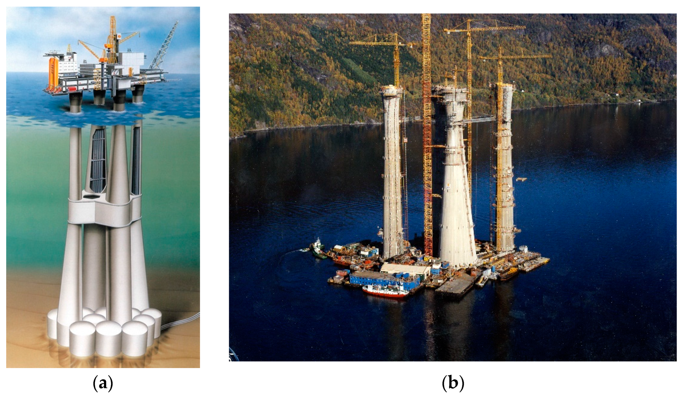
3.2. Installation of Large-Scale Subsea Structures

Many of the existing subsea structures and products in use today have been installed by specialized crane vessels. A structure would typically be built on land and then transported on an installation vessel or a barge to the desired location before finally being lifted and lowered to the seabed. With time, more and more of the processing equipment that was typically placed topside on platforms and vessels has been placed on the seabed. This development means that oil and gas fields further away from the existing infrastructure could be developed. Space limitations onboard existing platforms also mean that processing capability is difficult to increase without placing additional equipment on the seabed. With more and larger units to be installed, the crane capacities of the installation vessels needed to increase. Placing more and more critical equipment subsea also leads to a greater need to replace/repair equipment even in adverse weather. Adverse weather is typically a limiting factor in terms of offshore operations. Technological advances such as active heave compensation of cranes or bigger cranes can reduce the effects of adverse weather. Larger vessels also have reduced movement in adverse weather, leading to lower acceleration of the loads, however, larger and more specialized vessels are typically more expensive with higher dayrates. Feedback from the Åsgård compression project found that the need to install structures and modules in rough sea states required a specialized handling system on the vessel [27]. Specialized vessels are to be avoided in order to reduce installation and OPEX costs. The use of standard vessels enhances the availability of sufficient vessel capacity during unforeseen events and reduces costs by lowering the standby costs of specialized vessels.
Depending on the type of structure, a subsea structure typically has a design life of up to 30 years in a subsea environment. This prolonged operational phase requires the structures to withstand a range of environmental factors like corrosion, currents, impacts from fishing gear and bio growth. Despite their long operational life, the installation of these structures is relatively swift, often completed within a time span of weeks or months, weather permitting. Although the installation period is short considering the total design life, it is during this installation phase that the lifted structures especially are exposed to the highest loads. This is due to the dynamic effects of lifting from vessels exposed to the motion of the ocean. To handle these loads, the structure might need to be reinforced. These reinforcements not only increase material and construction costs but can also add to maintenance complexities without providing any operational advantages once installed at the seabed. Engineers must balance the need for ensuring that the structure is robust enough for the demanding installation phase without being excessively overbuilt for its operational life subsea.
To install a structure with a total mass exceeding the crane capacity, the structure would need to be split into smaller parts with individual masses below the crane capacity. Assembly of the sub-structures is then completed subsea before commissioning. This is how a large subsea gas compression station was installed at the Gullfaks field offshore Norway in 2015 [28].
An entirely different approach is to use submerged towing instead of lifting. Towing equipment submerged to its location offshore has been conducted for many years. With submerged towing, the object to be installed is lowered into the sea and then towed to its final location. If installation is completed by towing, the crane capacity is no longer a limiting factor and larger, more complex processing systems can be installed without dividing the system into smaller sub-structures. This significantly simplifies the commissioning and system integration testing. With the submerged towing technique, the natural buoyancy of the displaced water can be used to reduce the weight in water of the object. In addition, submerged towing also has reduced sensitivity to weather [29]. Waiting on weather occurs when weather conditions are so poor that no work can be completed, this can be the source of significant cost overruns since vessel charter costs will still be charged to project. Needless to say, the amount of waiting on weather should be minimized as far as possible.

3.3. Trawl Protection

Today’s sophisticated fishing methods include trawling, using trawl doors and clump weights to optimize catching of fish. Some of the trawl equipment can weigh over 5 tons and with typical trawl speeds of 1–2 m/s, the damage caused by impact can be significant. To protect critical structures and equipment, standards such as NORSOK-U001 [30] are extensively used in the NCS but the additional reinforcement of structures to handle impact loads from trawl equipment is a cost driver. Using good design principles based on experience could reduce impact loads and, thus, the design requirements. Tests performed by SINTEF2 and the authors on subsea structures showed that the design loads could be lowered by 50% [31]. Scaled testing also provides an overview of critical design parameters making it easier to optimize the design without jeopardizing the structural integrity.

3.4. Concrete Structural Design

To address the need for large offshore platforms in the NCS in the 1970s, the Concrete deepwater structure concept (Condeep) was developed, drawing upon the experience of large-scale onshore concrete structures. Over the course of two decades, from 1975 to 1995, a total of 14 of these large structures were built. Most of the Condeep structures were installed at water depths between 100 and 150 m but the largest, Troll A, is situated at a water depth of 300 m and was installed in 1995 [32]. To build Troll A, 245,000 m3 of concrete was needed [33]. The Condeep structures exemplify the durability of concrete as a building material for subsea tanks as the majority of the platforms are still in use today. Figure 4 shows the design and construction of a Condeep platform.
Although the concrete tanks were designed for oil and gas production, they can, in theory, be repurposed as energy storage tanks once the oil and gas production stops. The costs related to modification of the structures for energy storage are expected to be a fraction of the cost for construction and installation of a new structure. The Ekofisk tank, which is not a Condeep design, installed at 70 m water depth with a total storage capacity of about 160,000 m3 has been decommissioned and might also be a candidate for repurposing. Some of the tanks in the existing structures are likely to be contaminated from prolonged use with hydrocarbons and related production fluids. As a part of the repurposing, the tanks need to be either cleaned, as was the case with the Ekofisk tank during the decommissioning [34], or a filter needs to be placed at the outlet to reduce any contamination.
A simple calculation to show the potential value of repurposing Condeep structures Statfjord A and Troll A in addition to the Ekofisk tank is shown in Table 1. Due to the low tensile strength of concrete, there is an under-pressure condition on Statfjord A. To guarantee that the concrete tank is always in compression, the pressure in the tank is always 5 bar (approximately equal to 50 m water depth) lower than the hydrostatic pressure. To have an understanding of the value a repurposed structure could bring, an assumed roundtrip efficiency of η = 0.8 and a value of electricity of $0.1/kWh has been used.
The energy potential is calculated according to:
E p o t = V t o t a l ρ w g d a v g η
where V t o t a l is the total storage volume, ρ w the seawater density, g the acceleration due to gravity, and d a v g the average water depth.
The US Naval Civil Engineering laboratory (NCEL) initiated a series of tests in 1971 with the purpose of establishing how suitable concrete was for long term deep water subsea construction and if it could provide a long duration watertight construction [39]. In a handbook published by NCEL in 1986, it is stated that the specimens tested generally gained strength during the first 6 years of subsea (15% increase in strength) which then was relatively constant after 11 years of subsea use [40]. With regards to the absorption of water it was found, through testing of spherical specimens, that coated samples had no free water on the inside while uncoated specimens would absorb about “1 or 2 tablespoons of water per day” [39]. Interestingly, there was little corrosion noted in the steel reinforcement [39] and it is noted that concrete completely submerged in water typically does not see corrosion due to oxygen depletion in the surrounding seawater [40]. However, in the energy storage concept, this thinking is not applicable as the oxygen (air) in the tank can promote corrosion. Alternatives for reducing the corrosion potential could be the use of nitrogen instead of air or, more traditionally, making sure that the thickness of concrete around the rebar is sufficient to prevent corrosion [40].
The discharge and charge cycles of the SPHS would subject the concrete tank to load cycles as the pressure in the tank is increased and decreased. Pressure cycling on spherical test specimens did not reveal any significant decrease in strength when subjected to moderate pressure cycling frequencies [40] and no fatigue failures due to pressure cycling of storage tanks on the existing subsea concrete structures have been found [41]. Limiting the maximum pressure in the SPHS tanks, similar to the under-pressure condition in Statfjord A, could prevent any tensile stresses occurring which would significantly reduce the risk of fatigue failures. For an SPHS system with an initial pressure of p 0 = 1   bar placed at 1000 m water depth ( p o c e a n = 100   bar ) , limiting the maximum pressure in the tank to p t a n k = 95   bar would reduce the energy density (ref Equation (1)) to about 95% of the maximum possible. As shown in Figure 3, it might be necessary to reduce the utilization of the capacity to about 90% (for a C R = 100 ) to maintain the stable flow conditions necessary for efficient turbine operation in which case the under-pressure conditions would not put additional constraints on the operation of the SPHS system.
In addition to the developments with concrete for subsea use, advances in composites may provide additional cost savings. Traditionally, steel has been the main building block of oil and gas subsea structures but studies show that the introduction of composites in deep water structures could present significant cost savings [29].

4. Method

4.1. Structural Design

According to the design book for deepwater concrete structures, the stress state of a thick walled tubular structure close to implosion can be approximated to a uniform stress distribution [40]. This means that the formulas for thin walled pressure vessels can be used to calculate the implosion stresses although the radius to wall thickness ratio, n r = r o / w t might be > 10 which is the approximate limit for thinwalled solutions found in standard books such as [42].
The stress in a cylinder with outer diameter O D and wall thickness w t subjected to external pressure ( p l o a d ), under the assumption of uniform hoop stress ( σ h ) distribution, can be calculated according to the following formula:
σ h = p l o a d O D 2 w t
The load in this case is due to the hydrostatic pressure acting on the outside of the cylinder. The calculation assumes that the pressure on the inside of the cylinder is zero; this is considered a conservative assessment. The load as a function of water depth, h , can be formulated according to:
p l o a d = h ρ w g
With the addition of a general safety factor, n s , it is possible to calculate the required radius to wall thickness ratio as a function of water depth, h , for a given stress level. Combination of (3) and (4) gives:
O D 2 w t = 1 h ρ w g σ c n s = 1 h ρ w g σ c n s
σ c is the maximum compressive stress for the concrete. With regards to the safety factor, there are different interpretations on how large the total safety factor should be as shown in Table 2.
Standards such as such as Eurocode 4 [43] are not applicable to oil and gas subsea concrete structures which instead rely on DNV-ST-C502 Offshore concrete structures [44].
Table 2. Safety factors.
SourceTotal Safety Factor n s [-]CommentRef.
DNV-ST-C502
Offshore concrete structures
3 Includes a load factor n f = 1.4 . The total safety factor depends on the compressive strength of the concrete and an approximate number is shown in this table.[44]
NCEL 2.5 Based on experimental data. Structure not to contain people.[40]
ORES 1.5 [5]
Consequences of a catastrophic structural failure for a subsea concrete oil tank are severe in terms of human safety, environmental and financial aspects. It should be questioned if standards such as DNV-ST-C502 are relevant for a concrete tank used to store energy in terms of seawater. The environmental and human safety consequences of a failure in such a tank would be very limited, if any at all. The handbook published by NCEL is based on experimental data and is likely, therefore, more relevant, but it perhaps does not take into account developments within concrete technology since the experiments were carried out in the 1970–1980s. The analysis performed by Slocum, Fennell [5] uses a safety factor of 1.5. Assuming that there have been improvements with regards to concrete technology, that would justify a total safety factor of n s = 2 , somewhere between the NCEL and ORES data.
Table 2 shows that it is possible to calculate the needed buoyancy per energy as a function of water depth. This is completed by first rewriting (1) so that it becomes a function of the water depth using (4):
ϵ i s o = p 0 h ρ w g p 0 1 ln h ρ w g p 0
The total energy of a tank, E t o t a l , with internal volume, V t a n k , as a function of water depth is then:
E t o t a l = η R V t a n k ϵ i s o = η R p 0 V t a n k h ρ w g p 0 1 ln h ρ w g p 0
where η R represents the roundtrip efficiency of the system.
The internal volume of a tank with outer diameter, O D , wall thickness, w t and length, L t a n k :
V t a n k = π 4 O D 2 w t 2 L t a n k
The weight in water of a tubular structure with outer diameter, O D , and wall thickness, w t , becomes:
F w a t e r = ρ w π 4 O D 2 L t a n k ρ c π w t O D w t L t a n k
where F w a t e r > 0 means that the structure is naturally buoyant. Note that it has been assumed that the density of the air inside the tubular can be neglected ( ρ a i r ρ w ). The amount of buoyancy needed per energy storage capacity, γ , is found by combining (7)–(9):
γ = F w a t e r E t o t a l = 1 1 n s h ρ w g σ c 2 ρ w 1 1 n s h ρ w g σ c 2 1 ρ c η R h ρ w g p 0 1 + ln h ρ w g p 0
In Section 3 it was shown that for larger structures, submerged towing would be a very cost-efficient method for the installation of large concrete structures but that requires a net buoyant structure for the relevant water depth. A structure that is too buoyant (<0 in Figure 5) can be made neutral by adding weights in the form of additional concrete or by the use of ballast tanks similar to the ones found in submarines. Rock or sand dumping on top of the structure is a common way of increasing stability of subsea structures and protecting them from damage once installed at the seabed. Although the additional weight needed to compensate for the inherent buoyancy is costly, the cost of adding artificial buoyancy to a structure that is heavy is much higher and should be avoided as far as possible.
To calculate the total amount of concrete needed, the work will be split into two parts: one where additional buoyancy is needed, and one where additional ballast is needed to make the structure neutrally buoyant.

4.1.1. Ballast Needed

In a scenario where the structure is too buoyant and additional weight is required, additional mass in the form of concrete without air voids can be added. Note that in this situation, the relationship:
1 1 n s h ρ w g σ c 2 ρ w 1 1 n s h ρ w g σ c 2 1 ρ c in   ( 10 )   is > 0
The required additional mass of concrete is:
m a d d , c V a d d , c ρ w V t a n k = 1 1 n s h ρ w g σ c 2 ρ w 1 1 n s h ρ w g σ c 2 1 ρ c
where m a d d , c and V a d d , c   is the mass resp volume of the additional concrete required for a neutrally buoyant structure in water, note that m a d d , c = V a d d , c ρ c (11) is only valid when additional concrete is required to increase the weight in water of the structure. Solving for m a d d , c and simplification gives:
m a d d , c = 1 1 n s h ρ w g σ c 2 ρ w 1 1 n s h ρ w g σ c 2 1 ρ c 1 ρ w ρ c V t a n k
For a case where additional concrete is required, the total amount of concrete, Σ m c o n c , is calculated by a combination of (10) and (12):
Σ m c o n c E t o t a l = 1 + 1 1 ρ w ρ c 1 1 n s h ρ w g σ c 2 ρ w 1 1 n s h ρ w g σ c 2 1 ρ c η R h ρ w g p 0 p 0 ln h ρ w g p 0

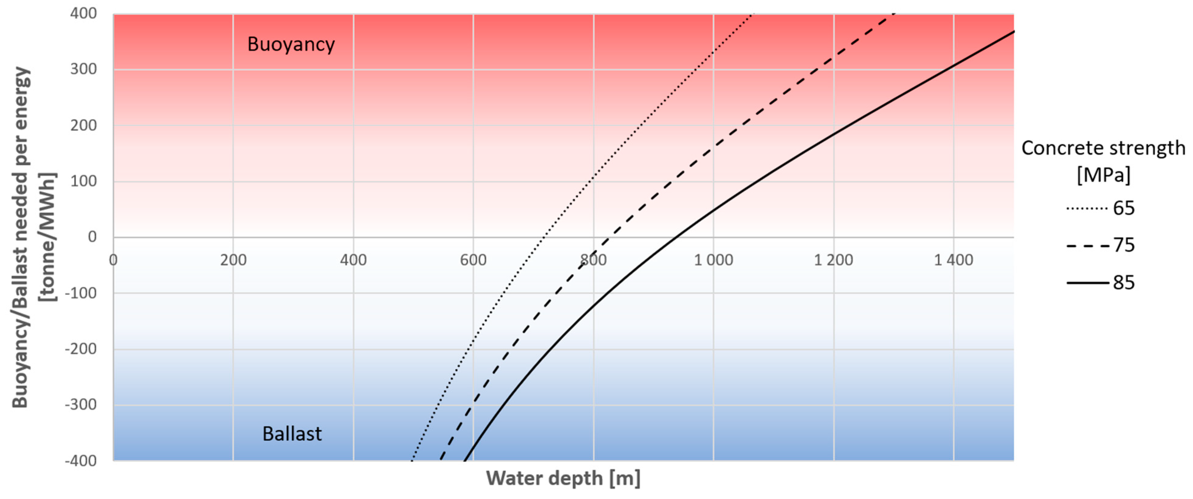
4.1.2. Buoyancy Needed

In the second case where additional buoyancy is needed, the 2 w t / O D ratio (ref (5)) required by the given water depth does not result in a structure that floats. Adding an air-filled concrete tank would not increase the buoyancy as the concrete weight is higher than the buoyancy provided by the additional tank. Other options are needed to provide buoyancy in such cases; this could be achieved by the use of low-density composite buoyancy modules. The additional buoyancy is calculated by:
1 1 n s h ρ w g σ c 2 1 ρ c 1 1 n s h ρ w g σ c 2 ρ w
The required volume of buoyancy needed is given by:
V b ρ w V b ρ b V t a n k = 1 1 n s h ρ w g σ c 2 1 ρ c 1 1 n s h ρ w g σ c 2 ρ w
V b and ρ b is the volume resp density of the buoyancy, the relation, m b = V b ρ b , can be used to calculate the mass of required buoyancy:
m b = 1 1 n s h ρ w g σ c 2 1 ρ c 1 1 n s h ρ w g σ c 2 ρ w ρ w ρ b 1 V t a n k

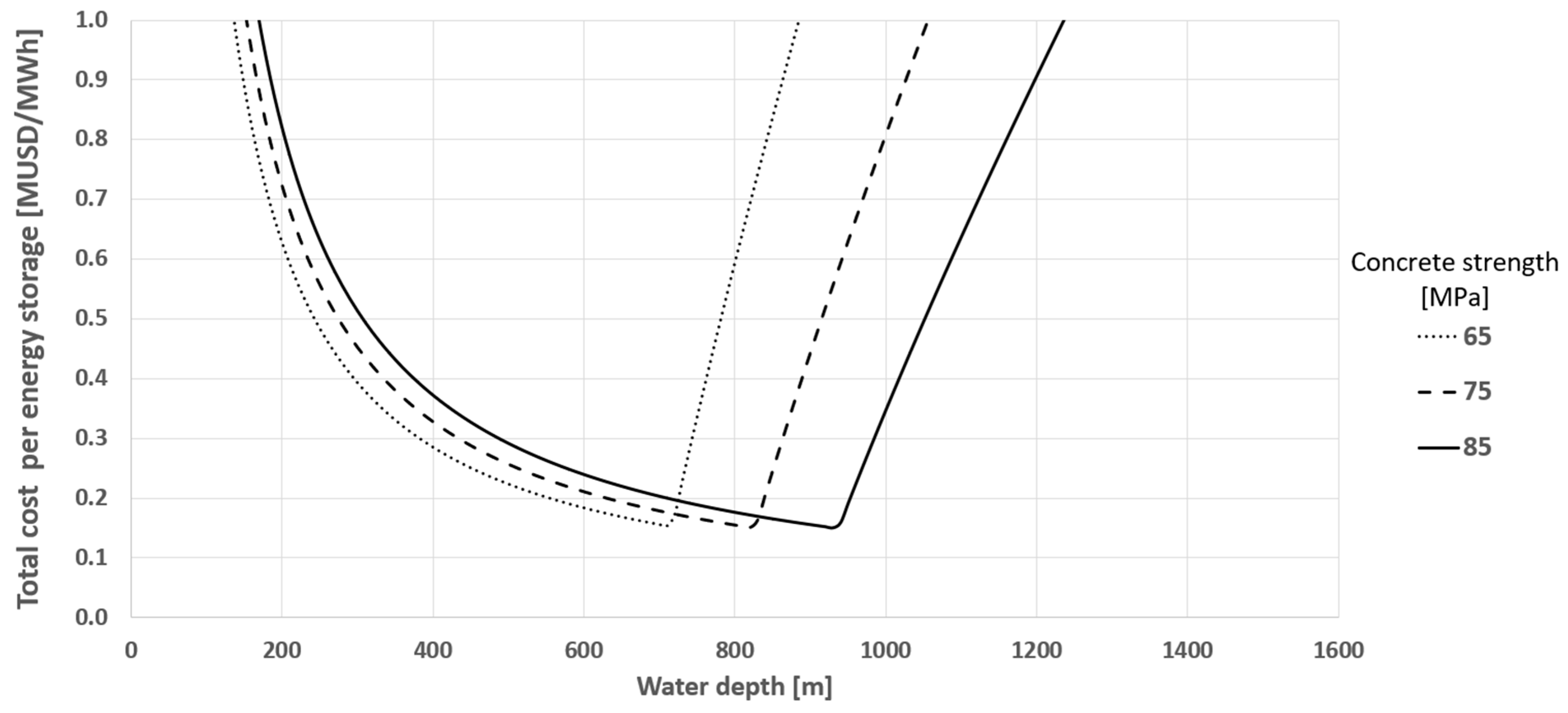
4.2. Total Cost Storage Tank per Energy

The total cost for a tank per energy as a function of water depth is the sum of the cost of concrete and the cost of the additional buoyancy if required. Consultations with concrete experts at the University of Stavanger concrete lab led to the estimated cost of concrete per weight as shown in Table 3. The cost of $132.9/ton for C65 was extrapolated to estimate costs of C75 and C85. Note that the use of extrapolated data is a simplification.
Discussions with relevant offshore buoyancy suppliers (to name a few: Trelleborg3, Matrix solutions4 and Balmoral5) related to composite buoyancy showed, assuming large volumes required, that a lower estimated cost would be around $4/kg uplift as shown in Table 4. Buoyancy costs are given as the cost per kg of uplift generated when fully submerged in water.

5. Results and Discussion

5.1. Buoyancy and Ballast Requirements

Using the input in Table 5, it is possible to plot the buoyancy/ballast needed for a buoyant tubular structure per energy as a function of water depth, see Figure 5. Note that ballast tanks providing buoyancy is not possible as soon as the graph in Figure 5 is above 0. For this case, a cylinder shape cannot be made neutrally buoyant in water due to the low ratio between the outer radius and the wall thickness.
It should be noted that the ballast required to provide a neutrally buoyant structure will be added in the form of air-filled ballast tanks. As such, they will provide buoyancy during towing, and when the structure is to be installed at the seabed, the ballast tanks will be flooded to provide the needed additional weight in water of the structure.

5.2. Total Cost Storage Tank

Using Table 3 and Table 4 and the equations in (10) and (13) a total cost of concrete per energy can be generated as shown in Figure 6. The lowest cost and the corresponding water depth are presented in Table 6.
The results in Figure 6 show that for water depths <700 m, the three different types of concrete used in the calculation require additional mass to become neutrally buoyant. The ratio 2 w t / O D (ref (5)) increases with the water depth as greater wall thicknesses are required to compensate for the hydrostatic pressure but, increasing water depths also augment the energy density as shown in Figure 2, and the total cost per energy storage therefore decreases with water depth until around 700 m water depth. If additional composite buoyancy is required to create uplift, the total cost increases rapidly due to the high cost of buoyancy.
Renting composite buoyancy used only for installation could be an attractive solution leading to lower costs for buoyancy than as shown in Table 4; however, this has not been within the scope of this paper. The results are also limited to show costs related to long cylindrical tanks. However, the results show that any additional buoyancy is associated with significantly higher costs, and it should be noted that the costs stated in Table 4 are a low estimate. Yet, the cost of additional buoyancy could be justified if the estimated energy storage revenues are sufficiently high. If that is not the case, it is likely that the maximum water depth is limited to where a certain concrete type can be used to make a neutral tank.
Since no commercial SPHS plants exist, there is no published data that can be used to benchmark the results in Figure 6 with other concepts. Costs related to the StEnSea SPHS concept, which utilises spherical tank design, has been presented by Hahn, Hau [8] but, as the authors note, there is no large-scale operational experience with the concept and the cost estimates are based on several assumptions.

5.3. Further Work

The results in this document are generally presented as a function of water depth. However, cost is also a function of distance from shore. Evaluating cost as a function of distance from shore would need to consider several complex factors such as the transition from AC to DC power for longer distances, the costs of transformers and the location of the energy storage in relation to offshore renewables and the offshore substation. A comprehensive analysis of these aspects is beyond the scope of this study and will be addressed in a subsequent paper.

6. Conclusions

To facilitate the energy transition and the rapid increase in intermittent power sources, the demand for energy storage continues to grow. While PHS is a proven and mature technology, further expansion is potentially limited by the lack of suitable topography. The oceans, an often-overlooked region and underestimated potential for energy storage, offer a promising solution for utility-scale SPHS. This study addresses the gap in quantified cost analysis for subsea storage tanks by presenting current best practices in subsea engineering and a robust methodology for cost estimation.
The proven durability of Condeep platforms demonstrates the feasibility of designing long-lasting subsea concrete structures for harsh environments. Developments within subsea control systems now show that fully electrified control systems are not only possible but already in use where step-out lengths of several hundred kilometers pave the way for remotely operated subsea energy storage concepts.
Cost-effective installation methods, such as towing instead of lifting, minimize CAPEX by reducing the need for heavy lift vessels and additional buoyancy or ballast. Design optimizations, including reduced impact loads from fishing gear, further lower costs and improve system resilience.
In sum, the work completed in this article has shown that cost per energy storage for a subsea concrete tank is around 0.15 M$/MWh in water depths between 700 and 900 m. The associated energy densities with these water depths are 1810 and 2360 Wh/m3 (energy per storage volume of tank).

Author Contributions

Conceptualization, R.J.; Methodology, R.J.; Validation, A.H.S. and M.A.; Formal Analysis, R.J.; writing—original draft preparation, R.J.; writing—review and editing, A.H.S. and M.A.; Visualization, R.J.; Supervision, M.A.; project administration, R.J.; funding acquisition, R.J. All authors have read and agreed to the published version of the manuscript.

Funding

This research was partly funded by the Research Council of Norway, grant number 320663. Rasmus Juhlin reports partial financial support was provided by Subsea7.

Institutional Review Board Statement

Not applicable.

Informed Consent Statement

Not applicable.

Data Availability Statement

Data is contained within the article.

Acknowledgments

The authors would like to thank the Norwegian Research Council and Subsea 7 for funding with regards to research within subsea energy storage. Special thanks to Daniel Karunakaran for providing supervision and reviewing this paper prior to submission. In addition, the authors would like to thank Yuri Novoseltsev and Kari Klokkeide at Subsea 7 for providing valuable insight into marine operations and Paul Chang for sharing his expertise within subsea control systems. John Grønli also deserves a special mention for his valuable input with regards to concrete.

Conflicts of Interest

Rasmus Juhlin reports a relationship with Subsea7 that includes employment. Rasmus Juhlin has patent #WO2020084150A2 issued to Subsea7 Norway AS.

Notes

1
https://www.onesubsea.slb.com/ (accessed on 11 December 2024).
2
www.sintef.no (accessed on 11 December 2024)
3
4
5

References

  1. Juhlin, R.; Assadi, M. Lessons from the Offshore Oil and Gas Industry for Hydro-Pneumatic Subsea Energy Storage Concepts. In Proceedings of the International Conference of Applied Energy (ICAE), Bochum, Germany, 8–11 August 2022; Volume 28. [Google Scholar] [CrossRef]
  2. IEA. Battery Innovation Must Drive the 50-Fold Increase in Storage Capacity Needed by 2040; IEA: Paris, France, 2020. [Google Scholar]
  3. Schmidt, O.; Melchior, S.; Hawkes, A.; Staffell, I. Projecting the Future Levelized Cost of Electricity Storage Technologies. Joule 2019, 3, 81–100. [Google Scholar] [CrossRef]
  4. Mongird, K.; Viswanathan, V.V.; Balducci, P.J.; Alam MJ, E.; Fotedar, V.; Koritarov, V.S.; Hadjerioua, B. Energy Storage Technology and Cost Characterization Report; Pacific Northwest National Laboratory (PNNL): Richland, WA, USA, 2019; p. 120. [Google Scholar]
  5. Slocum, A.H.; Fennell, G.E.; Dundar, G.; Hodder, B.G.; Meredith, J.D.C.; Sager, M.A. Ocean Renewable Energy Storage (ORES) System: Analysis of an Undersea Energy Storage Concept. Proc. IEEE 2013, 101, 906–924. [Google Scholar] [CrossRef]
  6. Cazzaniga, R.; Cicu, M.; Marrana, T.; Rosa-Clot, M.; Rosa-Clot, P.; Tina, G.M. DOGES: Deep ocean gravitational energy storage. J. Energy Storage 2017, 14, 264–270. [Google Scholar] [CrossRef]
  7. Puchta, M.; Bard, J.; Dick, C.; Hau, D.; Krautkremer, B.; Thalemann, F.; Hahn, H. Development and testing of a novel offshore pumped storage concept for storing energy at sea−Stensea. J. Energy Storage 2017, 14, 271–275. [Google Scholar] [CrossRef]
  8. Hahn, H.; Hau, D.; Dick, C.; Puchta, M. Techno-economic assessment of a subsea energy storage technology for power balancing services. Energy 2017, 133, 121–127. [Google Scholar] [CrossRef]
  9. Almén, J.; Falk, J. Subsea Pumped Hydro Storage A Technology Assessment. In Department of Energy and Environment; CHALMERS University of Technology: Gothenburg, Sweden, 2013. [Google Scholar]
  10. Juhlin, R.; Assadi, M. Investigations of the thermodynamic efficiency limits of a novel subsea energy storage concept. Appl. Energy 2023, 330, 120338. [Google Scholar] [CrossRef]
  11. Juhlin, R.; Assadi, M. Harnessing ocean depths for energy: A theoretical framework for evaluating the feasibility of Subsea Pumped Hydro Storage. J. Energy Storage 2024, 83, 110510. [Google Scholar] [CrossRef]
  12. Musial, W.; Hitt, C.C.; Sloan, C.; Pilot, J.; Groenveld, K. National Offshore Wind Research and Development Consortium-Research and Development Roadmap 3.0; National Offshore Wind Research and Development Consortium: Albany, NY, USA, 2021. [Google Scholar]
  13. Collins, L. Energy islands plan for North Sea ‘feasible’, says consortium. Recharge. 2019. Available online: https://www.rechargenews.com/wind/energy-islands-plan-for-north-sea-feasible-says-consortium/2-1-635620 (accessed on 11 December 2024).
  14. Jones, C.; Low Carbon Contracts Company, L.C.C. CfD Co-Location Generator Guidance Version 1. 2023. Available online: https://www.lowcarboncontracts.uk/resources/guidance-and-publications/cfd-co-location-generator-guidance/ (accessed on 11 December 2024).
  15. Juhlin, R.; Eren, E.; Kloster, E.; Hoen, M.; Hörler, M.; Kharabe, S.; Buhagiar, D. Increasing revenues of offshore wind farms with co-located energy storage systems. J. Phys. Conf. Ser. 2024, 2875, 012038. [Google Scholar] [CrossRef]
  16. Equinor. Equinor Put Trollvind on Hold. 2023. Available online: https://www.equinor.com/news/20230522-trollvind-on-hold (accessed on 11 December 2024).
  17. Norfolk Boreas: Work on Offshore Wind Farm Stops over Soaring Costs. BBC 2023. Available online: https://www.bbc.com/news/uk-england-norfolk-66263340 (accessed on 11 December 2024).
  18. Mooney, D. Large-Scale Energy Storage. In Stanford University Global Climate & Energy Project; Stanford University: Stanford, CA, USA, 2015. [Google Scholar]
  19. Buhagiar, D.; Sant, T.; Farrugia, R.N.; Aquilina, L.; Farrugia, D.; Strati, F.M. Small-scale Experimental Testing of a Novel Marine Floating Platform with Integrated Hydro-pneumatic Energy Storage. J. Energy Storage 2019, 24, 100774. [Google Scholar] [CrossRef]
  20. Olsen, A. 20 Years of Subsea Boosting Technology Development. In Marine, Construction & Engineering Deepwater Development (MCEDD); OneSubsea: Houston, TX, USA, 2014. [Google Scholar]
  21. Increasing Deepwater Reservoir Recovery with Subsea Boosting Technology. Scandinavian Oil-Gas Magazine, 2015; No 5/6. 53–54.
  22. Tønnesen, H.; Hadland, G. Oil and Gas Fields in Norway. Industrial Heritage Plan; Norwegian Petroleum Museum: Stavanger, Norway, 2011; p. 268. [Google Scholar]
  23. Schwerdtfeger, T.; Scott, B.; Akker, J.v.d. World-First All-Electric Subsea Well. In Proceedings of the Offshore Technology Conference, Aberdeen, UK, 5–8 September 2017; p. D031S038R002. [Google Scholar]
  24. Hallset, J.-O. Ormen Lange Fase 3-Undervannskompresjon; Shell, A.S.N., Ed.; Norwegian Offshore Directorate: Stavanger, Norway, 2022.
  25. Petoro. PUD for Ormen Lange Undervannskompresjon; Petoro: Stavanger, Norway, 2021. [Google Scholar]
  26. Narayanaswamy, V. Review of challenges in reliable electric power delivery to remote deep water enhanced oil recovery systems. Appl. Ocean Res. 2013, 43, 53–67. [Google Scholar] [CrossRef]
  27. Storstenvik, A. Subsea Compression-Designing and Building a Subsea Compressor Station. In Proceedings of the Offshore Technology Conference, Houston, TX, USA, 2 May 2016. [Google Scholar]
  28. Birkeland, B.; Bøe, C.; Jensen, R.O. Gullfaks Subsea Compression-Subsea Commissioning, Start-Up and Operational Experiences. In Proceedings of the Offshore Technology Conference, Houston, TX, USA, 2–5 May 2016; p. D021S024R005. [Google Scholar]
  29. Daasvatn, S.; Juhlin, R.; Sæterdal, M. Modular Integration Platform–Submerged Production Unit for Large Subsea Plants. In Proceedings of the Offshore Technology Conference, Houston, TX, USA, 30 April–3 May 2018. [Google Scholar]
  30. NORSOK U-001:2021; Subsea Production Systems. NORSOK: Tingvoll, Norway, 2021.
  31. Wu, J.; Muthanna, C.; Alsos, H.; Juhlin, R.; Karunakaran, D. Experimental Investigation of Over-Trawlability of an Innovative Arctic Subsea Production Unit (SPU). In Proceedings of the ASME 2019 38th International Conference on Ocean, Offshore and Arctic Engineering, Glasgow, Scotland, 9–14 June 2019. [Google Scholar]
  32. Finn, S.; Marie, S.-S. Norwegian Contractors. 2020. Available online: https://snl.no/Norwegian_Contractors (accessed on 21 May 2023).
  33. Sandberg, F.H. Condeeps. The Dinosaurs of the North Sea. J. Energy Hist./Rev. D’histoire L’énergie 2019, 2, 1l–15l. [Google Scholar]
  34. Sandberg, F.H. Ekofisk-Tanken–et Ikon Som Blir Stående. 2019. Available online: https://ekofisk.industriminne.no/nb/ekofisk-tanken-et-ikon-som-blir-staende/ (accessed on 21 May 2023).
  35. OLJEMUSEUM, N. Ekofisk 2/4 T. Available online: https://ekofisk.industriminne.no/nb/ekofisk-24-t/ (accessed on 21 May 2023).
  36. Petroleumstilsynet. Investigation of Overpressurisation in Sludge Cell 11 on Statfjord A on 26 November 2019; Petroleumstilsynet: Stavanger, Norway, 2020.
  37. The Statfjord Area. 2023. Available online: https://www.equinor.com/energy/statfjord (accessed on 22 May 2023).
  38. Andrei, M. Troll A–The Tallest Structure Ever Moved by Mankind. 2015. Available online: https://www.zmescience.com/other/offbeat-other/tallest-structure/ (accessed on 22 May 2023).
  39. Concrete for Deep Ocean Construction. Concrete Construction. 1983. Available online: https://www.concreteconstruction.net/how-to/materials/concrete-for-deep-ocean-construction_o (accessed on 11 December 2024).
  40. Haynes, H.H.; Rail, R.D. Handbook for Design Of Undersea, Pressure-Resistant Concrete Structures; Naval Civil Engineering Laboratory: Port Hueneme, CA, USA, 1986. [Google Scholar]
  41. Petroleum Safety Authority Norway. Ageing of Offshore Concrete Structures; Petroleum Safety Authority Norway: Stavanger, Norway, 2009.
  42. Young, W.C.; Budynas, R.G. Roark’s Formulas for Stress and Strain, 7th ed.; McGraw-Hill: New York, NY, USA, 2002. [Google Scholar]
  43. European Committee for Standardization. Eurocode 4-Design of composite steel and concrete structures. In Part 1–2: General Rules-Structural Fire Design; European Committee for Standardization: Brussels, Belgium, 2014. [Google Scholar]
  44. DNV. DNV-ST-C502 Offshore Concrete Structures; DNV: Høvik, Norway, 2021. [Google Scholar]
Figure 1. Power and fluid flows during charge and discharge for SPSH concept.
Jmse 12 02288 g001
Figure 2. Energy density as a function of water depth according to (1).
Jmse 12 02288 g002
Figure 3. Normalized flow as a function of water volume in the tank (VW) and volume of tank (Vtank) [1].
Jmse 12 02288 g003
Figure 4. (a) The Condeep platform concept (Norwegian Contractors/Norwegian Petroleum Museum); (b) A Condeep platform under construction in the fjords of Norway. (Norwegian Contractors/Norwegian Petroleum Museum).
Jmse 12 02288 g004
Figure 5. Buoyancy and ballast requirements.
Jmse 12 02288 g005
Figure 6. Estimated cost of tank per energy as a function of water depth.
Jmse 12 02288 g006
Table 1. Repurposing existing concrete structures.
Ekofisk TankTroll AStatfjord ARef.
Total storage capacity, V t o t a l [m3]160,000206,000288,000[35,36,37]
Max. Water depth [m]70300150[32,35]
Under-pressure condition [m]- 150 250[36]
Height of cell/tank [m]707070[36,38]
Aver. water depth to center of tank 3, d a v g [m]3521565
Round trip efficiency, η [-]0.80.80.8
Energy potential, E p o t [MWh]12.5138.441.8
Estimated value [$/kWh]$0.1$0.1$0.1
Discharge freq. [cycles/day]222
Gross value electricity/day [$]$2503$27,672$8366
Gross value electricity/year [$]$0.9M$10M$3M
Gross value electricity/20 years [$]$18M$202M$61M
1 No under-pressure condition for the Ekofisk tank has been found; 2 Assumed that the under-pressure condition on Statfjord A is also applicable to Troll A; 3  d a v g = M a x . W a t e r   d e p t h u n d e r   p r e s s u r e   c o n d i t i o n h e i g h t   o f   c e l l / t a n k 2 .
Table 3. Estimated cost of concrete.
ConcreteC65C75C85
Cost [$/tonne]132.9153.3194.2
Table 4. Estimated cost of composite low-density buoyancy.
Composite BuoyancyLowest Cost
Cost [$/kg uplift]4
Table 5. Input to Equation (10).
ParameterValueDescription
σ c 65 , 75 , 85   M P a Cylinder compressive strength for three different concrete grades: C65, C75 and C85 [44].
ρ w 1025   kg / m 3 Density of seawater.
ρ c 2600   kg / m 3 Density of concrete, including rebar.
n s 2 General safety factor, chosen according to a value between NCEL and ORES numbers in Table 2.
p 0 1   bar Initial pressure in tank. Assumed to be atmospheric pressure.
η R 0.8Assumed roundtrip efficiency.
Table 6. Lowest cost and related water depth.
Concrete TypeLowest Cost [M$/MWh]Corresponding Water Depth [m]
B650.153710
B750.152820
B850.150930
Disclaimer/Publisher’s Note: The statements, opinions and data contained in all publications are solely those of the individual author(s) and contributor(s) and not of MDPI and/or the editor(s). MDPI and/or the editor(s) disclaim responsibility for any injury to people or property resulting from any ideas, methods, instructions or products referred to in the content.

