Article

Covert Underwater Acoustic Communication Using Marine Ambient Noise Without Detectable Features

by
Biao Liu
1,*,
Jianchun Huang
2,
Ning Jia
2,
Biao Wang
1 and
Shengming Guo
2
1
Ocean College, Jiangsu University of Science and Technology, Zhenjiang 212100, China
2
Institute of Acoustics, Chinese Academy of Sciences, Beijing 100190, China
*
Author to whom correspondence should be addressed.
J. Mar. Sci. Eng. 2024, 12(12), 2217; https://doi.org/10.3390/jmse12122217
Submission received: 10 October 2024 / Revised: 31 October 2024 / Accepted: 26 November 2024 / Published: 3 December 2024

Abstract

:
Learning from steganography, this study considers ocean ambient noise as a carrier and proposes a covert underwater acoustic communication scheme without detectable and repetitive features. We modulate the information in the parameters of the steganography operation rather than the specific signal waveforms. The steganography operation mainly includes three steps: symmetrical division, phase rotation, and time–domain inversion. The rotation phases are related to the transmitted information. The receiver demodulates by performing the same operation, like transmitter without knowing transmitted waveforms. Therefore, we can use countless ocean ambient noise signals to transmit the same information, which can avoid repetitive features. To optimize the communication performance, the relationship between the demodulation output value and the rotation phases is derived, and the optimal modulation parameter setting methods of modulation are given. Finally, the simulation and sea trial results show that the bit error ratio of the studied covert underwater acoustic communication scheme is approximately 5 × 10⁻⁴ at a signal-to-noise ratio of −4 dB, which verifies the effectiveness of the scheme, and the rate is 4 bps. And the results of cyclic spectrum, cepstrum and square frequency-doubling methods show that the signal of the studied scheme does not have any detectable features.

1. Introduction

Covert underwater acoustic communication (CUAC) should avoid the detection of communication signals (i.e., signal concealment), feature extraction of the communication signal (feature stealth), and information interception (information security). Signal concealment and feature stealth generally belong to the low probability of detection (LPD) category, and the latter has further requirements for hiding communication activities. Information security can achieve a low probability of interception (LPI) [1]. Notably, encryption is not the only way to achieve LPI. Moreover, complex demodulation modes with special processes can achieve LPI [2].
The LPI schemes allow signals to be detected and mainly focus on protecting information security [3]. Therefore, it is difficult to protect the position concealment of both the transmitter and receiver effectively. Ref. [4] reported that covert communication is not only encryption but also hiding the existence of communication. No matter how difficult deciphering the information is, being identified as communication activities is more serious [5]. Therefore, LPD is the critical research goal of CUAC. Meanwhile, the CUAC scheme with LPI or LPD belongs to communication security (ComSec) and transmission security (TranSec) schemes, respectively.
To achieve LPD, the communication signal should avoid detectable features, such as spectrum and cyclic correlation [6]. Detectable features include two aspects: the inherent features of the carrier and the repeatability features caused by continuous transmission of the same carrier.
Presently, the spread-spectrum methods [7,8,9,10,11,12,13] and bionic schemes [14,15,16,17,18,19] are two main ways to realize CUAC. Spread-spectrum CUAC mainly reduces the power spectral density by spreading the spectrum, so that the transmitted signal is submerged in the background noise. The traditional approaches to obtaining broadband signals include spread-spectrum code and multiband modulation. Bionic CUAC hides the information in the marine mammal sounds, and the interceptor regards the communication signals as the activity of marine mammals to deceive the interceptor. Also, the deceptive hypothesis is the vital premise of bionic CUAC.
The information carriers of the spread spectrum or bionic CUAC are mostly some specific waveforms; i.e., the transmitted signal waveform is fixed when transmitting certain symbols many times. Therefore, the frequent transmission of communication signals introduces the repeatability feature. Moreover, if the way to transmit marine mammal sounds does not match biological habits, such as the number or waveform of transmitted signals are fixed, the spectral features may lead to the exposure of communication activities.
To detect the repetitive features, advanced detection technologies make the conventional modulated signal lose the LPD ability, such as the cyclic analysis method [20,21,22]. However, most modulated or artificial signals belong to cyclostationary signals with cyclic features [20,23]. Therefore, due to the potential periodic features, the cyclic analysis method can effectively detect the signal [24], estimate the modulation parameters [25,26], classify the signal [27], and identify the modulation system [28]. Ref. [26] applied cyclic analysis to estimate the carrier frequency and symbol period of underwater acoustic communication signals and further obtained the Doppler frequency shift. Note that cyclic analysis methods often do not need prior knowledge about the target signal [26].
Refs. [29,30,31,32,33] reported a new idea of realizing covert communication to eliminate repetitive features. By modulating the information into statistical parameters, the information was not singly mapped with the waveforms to avoid the repeatability of communication signals. Ref. [29] modulated the information into the correlation polarity of two Gaussian distribution sequences and decoded it by detecting the correlation coefficient. In refs. [30,31], α-stable distributed noise was used as the carrier to modulate the information into the skewness of the signal, and the receiver detected the skewness through the SFLOM or FLOC algorithm for demodulation. Refs. [32,33] modulated the information into characteristic exponents of α-stable noise, which can be decoded by a logarithmic moment estimator. However, α-stable noise does not match the features of ocean ambient noise.
For underwater acoustic research, some scholars have applied steganography to sonar detection and communication. For active sonar with LPI, Lynch [1] reported that the detection signal waveform should be recognized as noise rather than a useful signal by the interceptor to avoid being detected. Park [34] designed a special sonar signal through steganography and background noise modeling to eliminate the significant change in the background noise features at the interceptor. Park called it a steganography sonar and verified its feasibility in shallow water through numerical simulation. Steganography sonar signal can be integrated with the ambient noise, which is also the main goal of steganography, i.e., to hide the existence of communication activities [35]. Passerieux [36] proposed a CUAC scheme based on a steganography algorithm using rainfall noise or biological sounds as the information carrier. With the steganography algorithm, the information transmission of this scheme uses no specific signals.
Steganography has two important advantages. First, the information does not depend on the specific carrier waveforms. Second, information carriage does not significantly change the carrier features. Therefore, one carrier can carry different information, and one piece of information can be modulated into various carriers. Even if the same information is transmitted infinitely, the signal remains unrepeated.
Learning from the idea of the steganography process, this study studies a CUAC scheme without detectable features using marine ambient noise as a carrier. The steganography process mainly comprises three steps, such as symmetric division, phase rotation, and time–domain reversion. The rotation phases for half of the segments are set as the phases of transmitted symbols. Moreover, an optimal modulation parameter strategy (OMPS) is proposed, and another half of the rotation phases are used to meet the strategy. Finally, numerical simulations and sea trial data were used to verify the studied steganography-based CUAC scheme.
The remainder of this article is organized as follows. In Section 2, the modulation and demodulation methods of the studied CUAC with steganography are introduced, and the OMPS is proposed. Section 3 verifies that there are no detectable features in the studied CUAC scheme and the effectiveness of the demodulation methods. Section 4 illustrates the sea trial results. Finally, conclusions and discussion are provided in Section 5.

2. System of Studied CUAC Schemes

This section will introduce the approach to modulation and demodulation based on steganography operation. Additionally, the relationship between the demodulation value and the steganography parameters will be derived to introduce the OMPS.

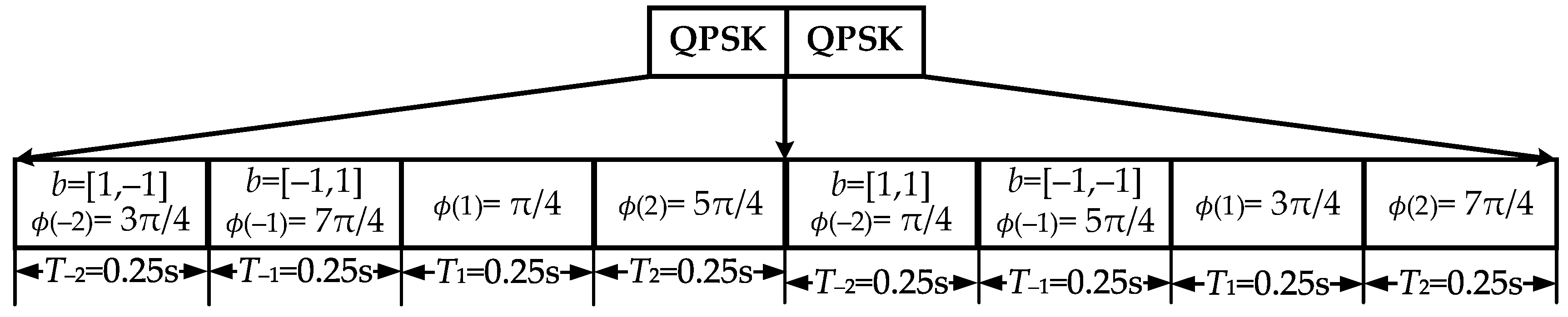
2.1. Modulation Method

The steganography comprises three steps: symmetrical division, phase rotation, and reversion. In this study, we adopt band-limited ambient noise to generate transmitted signal. In addition, the band-limited noise has been filtered by a bandpass filter according to the frequency band B of the transducer. We call the band-limited noise the initial signal and assume that the initial signal is band-limited white Gaussian noise. First, the initial signal x ( t ) with length of T x is symmetrically divided into N small segments, as follows
x n t = x t g n t n = ± N / 2 , , ± 2 , ± 1 g n t = 1       t n b < t < t n e 0       t else
where g n ( t ) , t n b , and t n e are the rectangular window and starting and ending times of n-th segment. So, the n-th duration T n is equal to t n e t n b and the same as T n .
Second, multiply each segment by some phases related to transmitted symbols, and call the phases rotation phases. Assuming that the index of any selected N / 2 segments is i = [ i 1 , i 2 , , i N / 2 ] , and the i n -th segment carries the symbol b n , the corresponding symbol sequence is b = [ b 1 , b 2 , , b N / 2 ] . Note that the rotation phases related to the symbol sequence b is ϕ s = [ ϕ N / 2 s , , ϕ 1 s , ϕ 1 s , , ϕ N / 2 s ] and half of the rotation phases represent the symbol phase in b , such as ϕ i n s = φ b i , i n i . At this time, the i n -th and i n -th segment signals are exp ( j ϕ i n s ) x i n ( t ) and e x p ( j ϕ i n s ) x i n ( t ) , respectively.
Finally, the signal is inverted in the time domain. So, the i n -th segment signal is e x p ( j ϕ i n s ) x i n ( t ) . After the above three steps, the information-bearing signal C x t based on the steganography process C is obtained as follows
C x t = n = N / 2 , n 0 N / 2 e j ϕ n s x n t
Then, the initial and the information-bearing signals are added to obtain the transmission signal s ( t ) .
s ( t ) = 1 2 x ( t ) + 1 2 C x ( t )
When generating communication signals for different transmission symbol sequences b , the transmitter adopts different rotation phase combinations ϕ s related to b . Therefore, the number of ϕ s used by the transmitter is the same as the number of symbol sequences b . Each symbol sequence b contains N / 2 symbols, so the number of b is equal to M N / 2 for the MPSK. Here, the QPSK symbol was adopted to generate b , so M is equal to 4 and there are 4 N / 2 rotation phase combinations ϕ s for the transmitter.

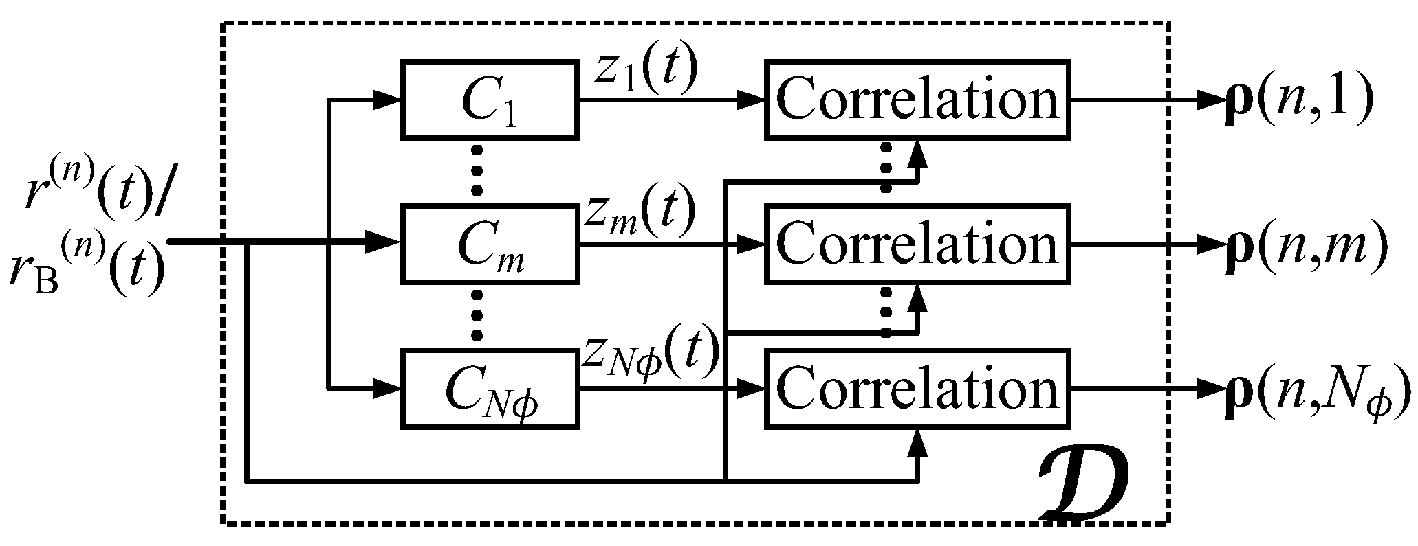
2.2. Demodulation Method

The modulation method based on steganography does not limit the waveform of the initial signal x ( t ) , as shown in Equation (2), so any ocean ambient noises can be used for generating a transmission signal. Even when transmitting the same symbol many times, the waveform of the transmitted signal will not be repeated. So, the receiver cannot have prior knowledge of the transmission waveforms. However, the receiver can demodulate according to the steganography process. The steganography process C of the rotation phase combination ϕ is recorded as C ϕ , and the steganography with ϕ s adopted by the transmitter is recorded as C s .
To demodulate, the receiver performs two main steps. First, steganography with ϕ is performed on the received signal to obtain the intermediate signal z ( t ) = C ϕ ( r ( t ) ) . In actual processing, the baseband signal r B ( t ) can be obtained by demodulating the received signal r ( t ) first with a raised-cosine filter. The following steps can be performed equivalently on r ( t ) and r B ( t ) . Here, we focus on the demodulation method based on steganography, so we take r ( t ) to illustrate the demodulation method and will summarize the step of the studied CUAC scheme realized in the baseband. Then, the intermediate signal is correlated with the received signal to obtain the demodulation value ρ ( ϕ ) as follows:
ρ ( ϕ ) = r t , z t = 1 T x r t z * t d t
where r ( t ) is the received signal. Note that the first half ϕ s ( f ) of ϕ s relates to the transmission information, which is determined, whereas the second half ϕ s ( b ) will be determined by OMPS, introduced later. Therefore, it is necessary to select an appropriate ϕ s ( b ) to optimize the communication performance. Next, the impact of C ϕ on the communication performance is analyzed under the Gaussian channel. The received signals, r ( t ) and z ( t ) are, respectively
r ( t ) = s t + w t = n = N / 2 , n 0 N / 2 1 2 x n t + 1 2 e j ϕ n s x n t + w n t
z ( t ) = n = N / 2 , n 0 N / 2 e j ϕ n 1 2 x n t + 1 2 e j ϕ n s x n t + w n t
where w t is the interference noise, and w n t = w t g n ( t ) .
Both the initial signals x ( t ) and interference noises w t are collected from the ocean environment, so there is poor cross-correlation between the divided signals x n ( t ) , x m ( t ) , w n ( t ) , and w m ( t ) as
< x n ( t ) , x m * ( t ) > = < x n ( t ) , x m * ( t ) > = σ 2 δ ( n m ) < x n ( t ) , x m * ( t ) > = < w n ( ± t ) , x m * ( ± t ) > = 0
where w n t = w t g n ( t ) and σ 2 are the power of x ( t ) . Substitute Equation (7) into Equation (4); the demodulation value in Equation (4) will be
ρ ( ϕ ) = σ 2 4 n = N / 2 . n 0 N / 2 T n e j ϕ n e j ϕ n s + e j ϕ n s
where σ n 2 is the power of x n ( t ) .
To achieve correct demodulation and optimal performance, ρ must be maximum when adopting ϕ = ϕ s as
ρ max = ρ ϕ s = 1 4 σ 2 n = N / 2 , n 0 N / 2 T n e j ( ϕ n s + ϕ n s ) + 1
According to Equation (9), ρ max is achieved and equal to σ 2 T x / 2 when ϕ n s + ϕ n s is equal to an even multiple of 2π. Therefore, the rotation phase ϕ n of the signal segment without transmission information should be 2 K n π ϕ n s , n i and K n is an integer. Thus, the OMPS is
ϕ s = ϕ N / 2 s , , ϕ 1 s , 2 K 1 π ϕ 1 s , , 2 K N / 2 π ϕ N / 2 s
For demodulating, ϕ should match with ϕ s . The first half of ϕ relates to the transmission information, and the phase of the other half satisfies Equation (10). Let ϕ n s = ϕ n s and ϕ n = ϕ n . Next, substitute these into Equation (8) to obtain
ρ ϕ = σ 2 n = 1 N / 2 T n cos ( ϕ n ϕ n s )
Obviously, when ϕ equals ϕ s or ϕ s + π , both absolute demodulation values culminate. However, their polarities are opposite (Equation (12)). If the absolute value is used for making a decision, the receiver cannot decode it effectively.
ρ ϕ s = σ 2 T ρ ϕ s + π = σ 2 T
From Equation (12), we can see that the demodulation only relies on the rotation phase and not the transmitted waveforms. Thus, the transmitter can use any waveforms to generate communication signals. For the ocean environment, the ambient noise will be a good choice due to its randomness and covertness. In short, the transmitter can convert the noise recorded at any time into a communication signal, even translating the same message many times.
ϕ s + π is recorded as ϕ s ( c ) , and ϕ s ( c ) also meets OMPS. The symbol sequences of ϕ s ( c ) and ϕ s are complementary. Thus, the symbol sequence of ϕ s ( c ) is b . Although the absolute values of ρ ( ϕ s ) and ρ ( ϕ s ( c ) ) are the same, their polarities are opposite. Therefore, the polarity of the demodulation value can also be used to make decisions. When the absolute value is the largest, and the polarity is positive, the receiver maps ϕ to the corresponding symbol sequence.
As mentioned above, the symbol sequence has a total of 4 N / 2 combinations, corresponding to the 4 N / 2 rotation phase combinations ϕ s . Similar to the demodulation, all 4 N / 2   ϕ s were used as steganography parameters to process the received signal to obtain 4 N / 2 intermediate signals. Afterward, 4 N / 2 demodulation values were obtained, and a decision was made among them. Fortunately, the absolute values of the first and second 4 N / 2 / 2 demodulation values are the same, but their polarities differ. Therefore, the receiver must adopt the first 4 N / 2 / 2 rotation phase combinations to obtain the 4 N / 2 / 2 demodulation values and determine the rotation phase combination ϕ ^ corresponding to the maximum absolute demodulation value. Afterward, the receiver further determines the polarity of the demodulation values with the maximum absolute value. If the polarity is positive, the hidden information is b ^ , corresponding to ϕ ^ . When the polarity is negative, the hidden information is b ^ , corresponding to ϕ ^ ( c ) . Therefore, the correlation times reduce by half from 4 N / 2 to 4 N / 2 / 2 . The two search methods are called full- and semi-search methods, respectively.
Next, QPSK was considered an example to further explain the full- and semi-search methods. The bits and phases corresponding to QPSK symbols are [1,1], [−1,1], [1,−1], [−1,−1], and π/4, 3π/4, 5π/4, and 7π/4, respectively. If the number N of divided segments of each noise signal is four, and two segments are used as the carrier of the symbols, then there are 4 2 kinds of symbol sequences. Assuming that the transmission symbol sequence is b = [ 1 , 1 , 1 , 1 ] , including symbols [1,1] and [−1,1], the rotation phase combination ϕ s is [ π / 4 , 3 π / 4 , 5 π / 4 , 7 π / 4 ] , and its complementary rotation phase combination ϕ s ( c ) is [ 5 π / 4 , 7 π / 4 , π / 4 , 3 π / 4 ] . Assuming that ϕ s and ϕ s ( c ) are used, the absolute values of the two demodulation values are the same, but the polarities differ. However, the symbol sequence corresponding to ϕ s ( c ) is [ 1 , 1 , 1 , 1 ] and is complementary to the transmitted b . Therefore, although the receiver does not fully match the rotation phase combination ϕ s of the transmitter, accuracy demodulation can be achieved by adopting the complementary rotation phase combination ϕ s ( c ) . When only half the number of rotation phase combinations are used for demodulation, the receiver can accurately decide according to the maximum correlation value and its polarity.

2.3. System Diagram

Herein, the time–frequency two-dimensional (2D) search method was used to degrade the influence of the Doppler shift. As shown in Figure 1, the receiver first resamples the received signal r ( t ) with the Doppler coefficient a n to obtain the signal r ( n ) ( t ) . Then, N ϕ = 4 N / 2 rotation phase combinations are used as steganography parameters to process the signal and obtain N ϕ intermediate signals. The intermediate signal obtained by the m-th steganography algorithm C m is z m ( t ) , and the correlation value between r ( n ) ( t ) and z m ( t ) is recorded as ρ ( n , m ) . For convenience, the processing for r ( n ) ( t ) is denoted as D , and the D can also be used to process the baseband signal r B ( n ) ( t ) .
Similarly, a correlation matrix ρ can be obtained by performing D on all compensated signals by different Doppler coefficients, { a 1 , a 2 , , a N a } .
The selected index of segment signals carrying the symbol does not affect the communication performance. To facilitate the derivation and avoid poor readability caused by disorderly index, the selected index is set as i = [ N / 2 , , 2 , 1 ] . Meanwhile, to make the performance of each segment consistent, a uniform division is adopted, so T n equals T x / N .
The modulation and demodulation can be realized in a baseband-like MPSK communication system. In this study, the raised-cosine function with a roll-off factor of 0.25 is used to obtain the baseband signal. In addition, synchronization and demodulation can be performed simultaneously. The receiver collects the signal via a sliding window and obtains a cross-correlation value between the received signal and intermediate signal as Equation (4). The synchronization is conducted according to the cross-correlation value. Like signal detection by matching filter, there are no peaks in the correlation value when communication activity does not exist. The pseudocode of the studied CUAC scheme is summarized below.
Step (1)
Filter the initial signal x ( t ) with raised-cosine function and down sample to obtain baseband signal x B ( t ) ;
Step (2)
Divide x B ( t ) into N small segments equally as Equation (1);
Step (3)
Select rotation phase combination ϕ s related to transmitted symbols b according to OMPS as Equation (10);
Step (4)
Multiply the rotation phases with N small segments as Equation (2) and modulate by raised-cosine function to obtain the information-bearing signal C x B t ;
Step (5)
Generate the transmitted baseband signal s B ( t ) as Equation (3);
Step (6)
Modulate s B ( t ) using raised-cosine function to obtain transmitted signal s ( t ) ;
Step (7)
Transmit or convolve s ( t ) with the channel, and obtain the received signal r ( t ) ;
Step (8)
Resample r ( t ) with Doppler coefficient a n , and obtain r ( n ) ( t ) ;
Step (9)
Filter r ( n ) ( t ) with raised-cosine function to obtain baseband signal r B ( n ) ( t ) ;
Step (10
Use the N ϕ steganography algorithms { C m } to obtain N ϕ intermediate signals as Equation (2);
Step (11)
Obtain the demodulation values ρ ( n , m ) , m = 1 , 2 , , N ϕ related to r B ( n ) ( t ) by cross-correlation as Equation (4);
Step (12)
Repeat Step 7–10 for each Doppler coefficient in { a 1 , a 2 , , a N a } and obtain the demodulation values ρ N ϕ × N a ;
Step (13)
Make decision according to the index n ^ ϕ of maximal values of ρ N ϕ × N a , and the b ^ is n ^ ϕ -th symbol sequence b .

3. Simulation Results

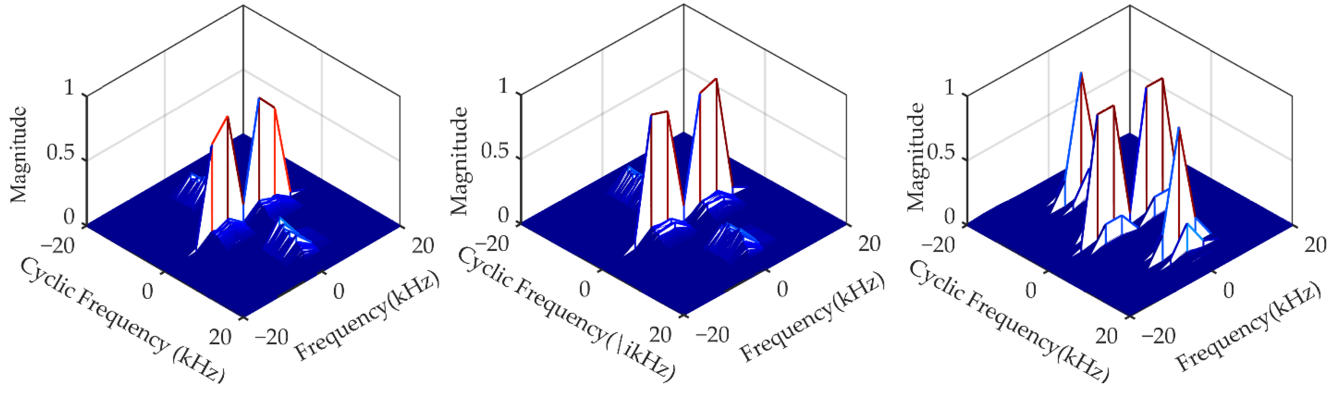
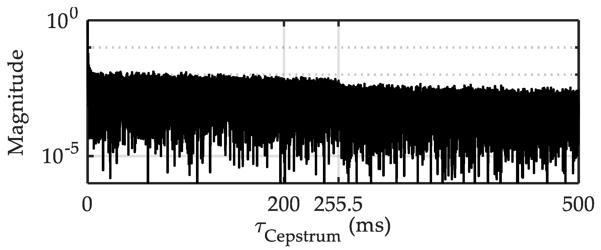
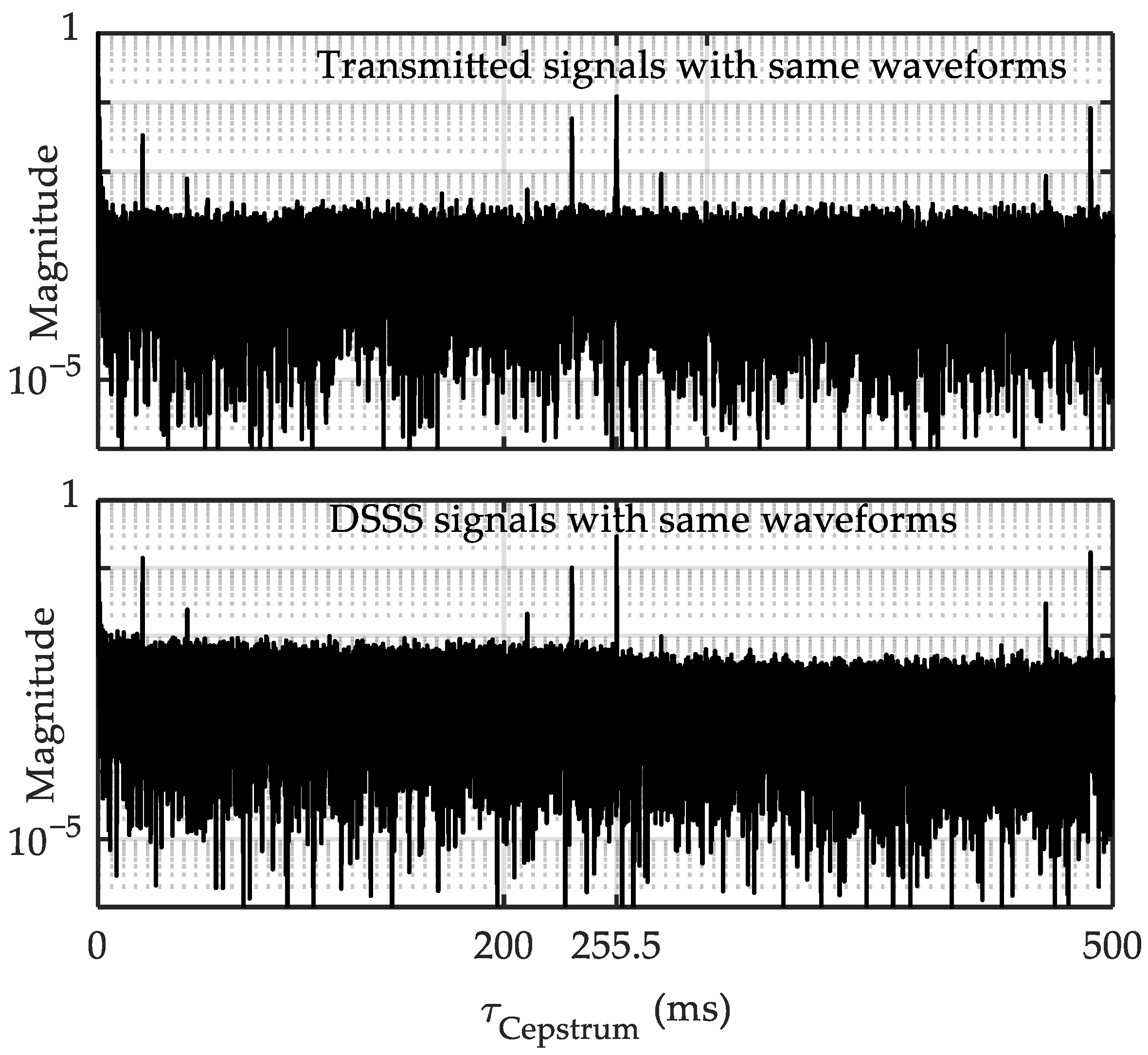
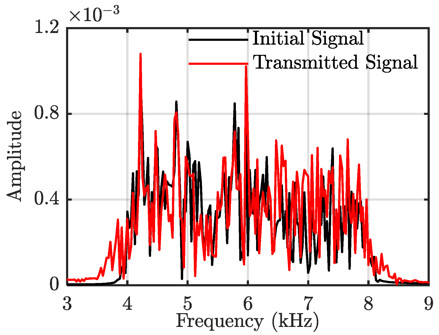
3.1. Signal Feature of the Studied CUAC

There are generally some detectable features for traditional modulated signals using specific detection methods. For example, the cyclic spectrum (CS) X CS ( f CS , f ) [20,21,22], cepstrum X Ceptrum ( τ ) [37] and square frequency-doubling method (SFDM) X SFDM ( f ) can be used to detect and even estimate carrier frequency and symbol period features, as
X CS ( f CS , f ) = x ( t ) , x * ( t + τ ) e j 2 π ( f CS t + f τ ) d t d τ X Ceptrum ( τ Cepstrum ) = IFFT ln FFT x ( t ) 2 X SFDM ( f ) = FFT x 2 ( t )
where f CS and τ Cepstrum are the cyclic frequency of CS and pseudo-time of cepstrum, respectively.
We will compare the features of the transmitted signal of the studied CUAC with those of the initial noise signal and direct sequence spread-spectrum (DSSS) signal. The initial noise signal is used to generate a transmitted signal via the modulation method in Section 2.1. The bandwidths of all three signals are 4–8 kHz. DSSS adopts a nine-order sequence, and its symbol period is 0.2555 s. Evidently, DSSS has significant features in the CS, especially at twice the carrier frequency 2 f c and 2 f c ± 1 / T c .
Figure 2 represents the CS of the three types of signals, in which the transmitted signal has no obvious features. For both the frequency and cyclic frequency domain, the CS magnitude of DSSS is pronounced and almost the same. No obvious peak occurs in the cyclic frequency domain of both the initial and transmitted signal. In addition, the CS of the transmitted signal looks like ocean ambient noise, so the CS analysis method does not work on the CUAC.
Further, we use CS and SFDM to estimate the carrier frequency of the transmitted signal and DSSS signal and adopt the normalized mean square error (NMSE) to compare the performance of the two methods, as
NMSE = 1 N α ^ i = 1 N α ^ α ^ i α 2 α
where α is the real value and α ^ i is the i -th estimation value. N α ^ is the simulation times. Here, α is carrier frequency.
The carrier frequency estimation error of DSSS and the transmitted signal is shown in Figure 3, and simulation time N α ^ is 1000. Both estimation methods can detect the existence of a DSSS signal but cannot estimate the carrier frequency of the transmitted signal. For the DSSS signal, the SFDM can reach an error of 10−4 in –6 dB, indicating that the accuracy is approximately 0.6 Hz.
Cepstrum analysis is a common method in speech signal processing for obtaining the pitch period of voiced components, i.e., low-frequency components. In this study, we use cepstrum to detect the feature of the symbol period. Figure 4 shows the cepstrum of four consecutive transmitted signals with a 0.2555 s duration, since the waveforms of four signals are different. Evidently, there are no observable features in the cepstrum. However, similar to the DSSS signal, when one segment of the noise signal is continuously used as the carrier, the interceptor can detect the repetitive features and even estimate the symbol period.
Next, to analyze the cepstrum features, we use the same four signals with polarities of +, −, +, and −, respectively, such as four transmitted signals and four DSSS signals with a period of 0.2555 s. Then, under an SNR of −5 dB, the cepstrums of both the transmitted signals and DSSS signals are obtained (Figure 5). The positions of the cepstrum peaks are almost the same, and the period parameter can be estimated as 255.5 ms approximately. Different from one segment of the transmitted signal in Figure 4, due to repetitive carriers, the same four segments have observable features similar to the DSSS signal. The cepstrum of the transmitted signal shows obvious features at positions similar to DSSS, such as 255.5 ms; thus, the symbol period can be observed. In short, the repetitive carrier causes observable features. Figure 6 further shows the estimation NMSE of the period for two signals using cepstrum. Even under an SNR range of −20 to −10 dB, both estimation errors are approximately 7.7 ms.
From the analysis above, we can see that it is difficult for the interceptor to detect the communication signal features using CS, cepstrum and SFDM. Any ambient noise can be used for modulation particularly, so the repetitive feature can be removed due to the modulation methods.

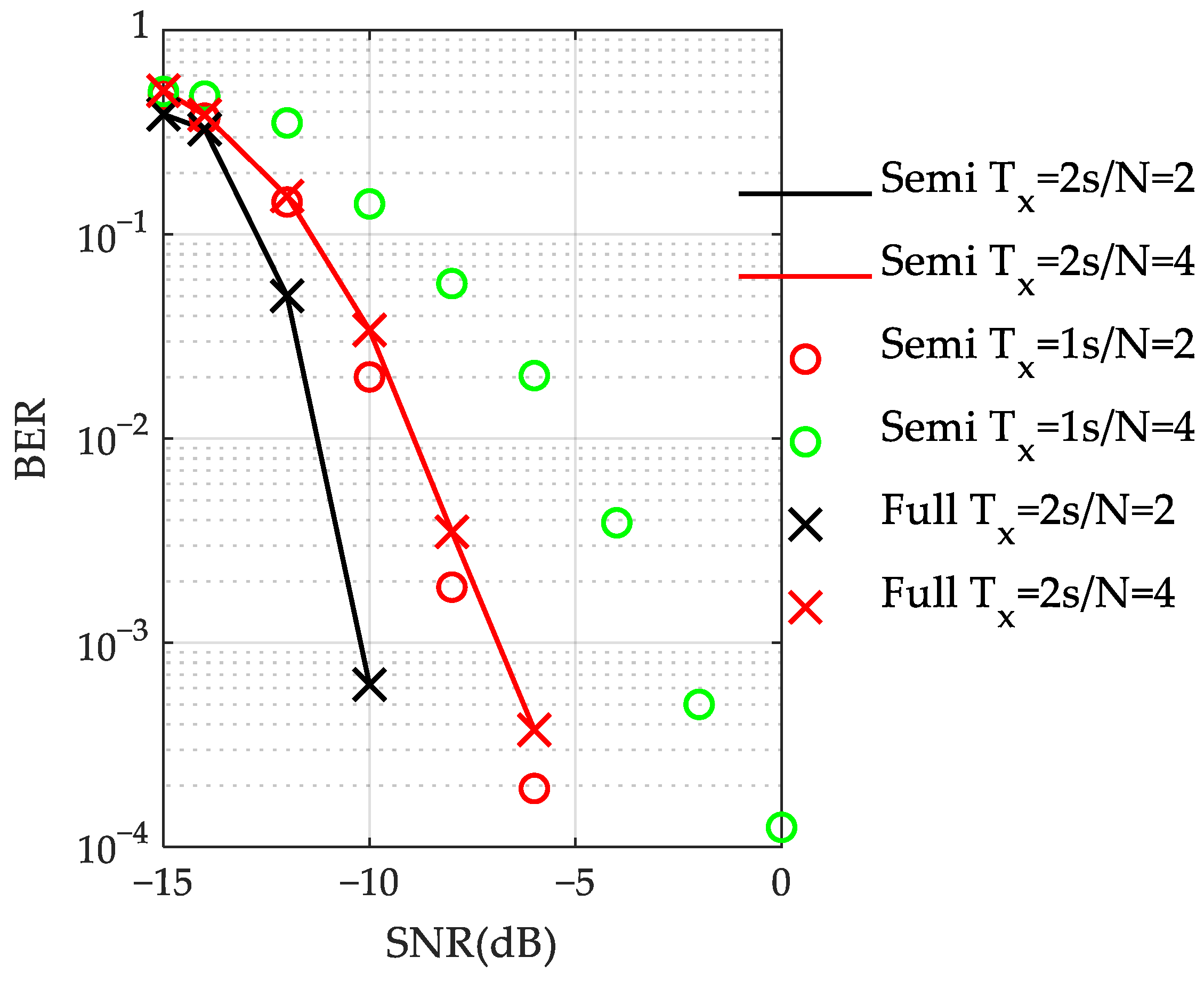
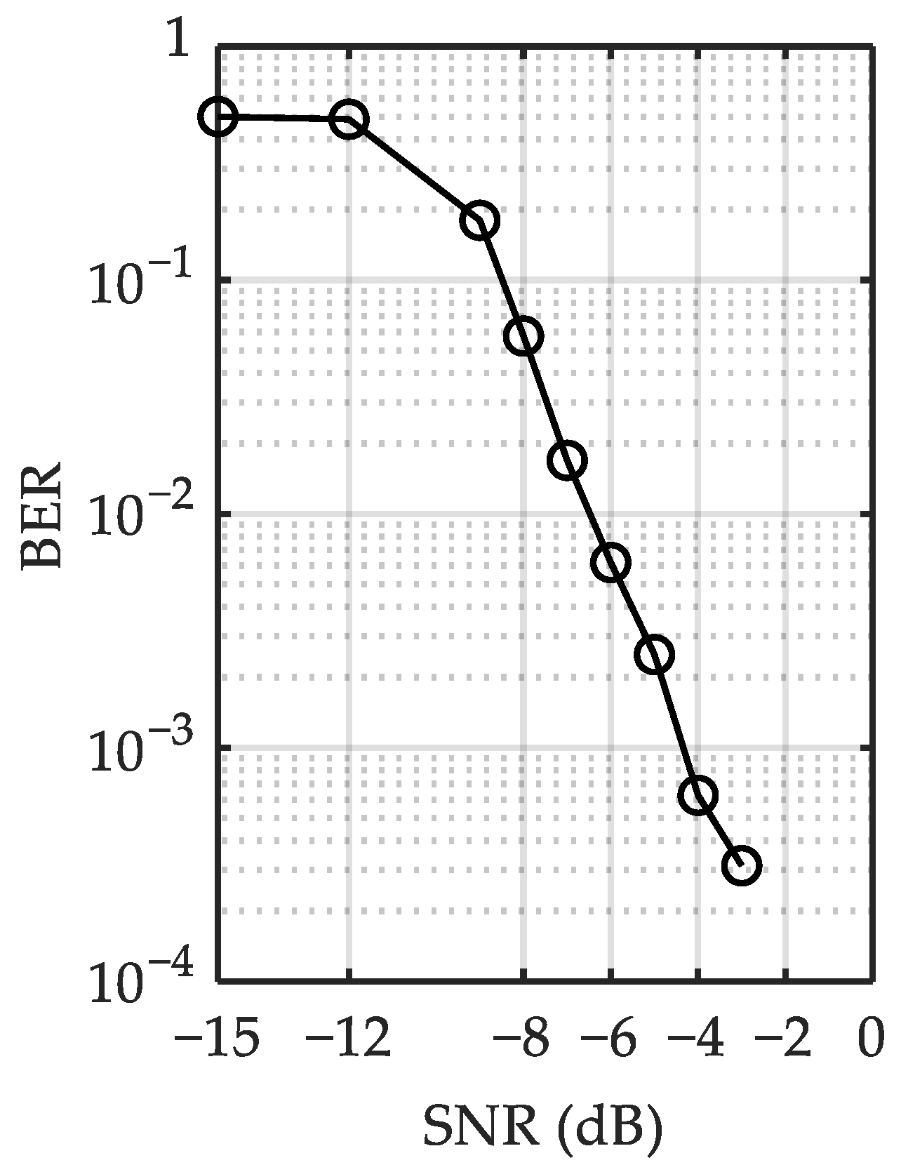
3.2. Simulation of the Studied CUAC

When ϕ s satisfies the OMPS, according to Equation (12), the correlation value ρ and communication performance are affected by T x and N . Taking the QPSK system as an example, this section qualitatively analyzes the impact on the performance using simulations and verifies that the semi- and full-search methods have the same performance.
We use WATERMAKER channel simulator MIME [38] to test the performance of the studied CUAC scheme. For the numerical simulations, the initial signal and the interference noise are the ocean ambient noise recorded in an actual sea trial. Meanwhile, the underwater acoustic channel used for simulation is measured from a sea trial. The frequency range of the initial signal is 4–8 kHz. Table 1 shows some sea trial settings corresponding to the measured channel, as shown in Figure 7. The number of symbols for each simulation is 2, namely 4 bits. We performed 4000 simulations for each SNR to obtain the BER curve.
Different numbers N of division segments and signal duration T x were set, respectively, and the parameters are shown in Table 2. Meanwhile, the rotation phase combinations satisfy the OMPS. The division pattern is uniform, so T n can be calculated according to N and T x .
The BER curves with different conditions are shown in Figure 8. When T x = 2 s, the performances of the full- and semi-search methods are the same for each N value. In other words, the semi-search method is equivalent to the full-search method and reduces calculation costs by half. In Figure 8, different colors represent different durations T n of each segment. When different parameter settings have the same T n , the BER curves are almost equivalent.

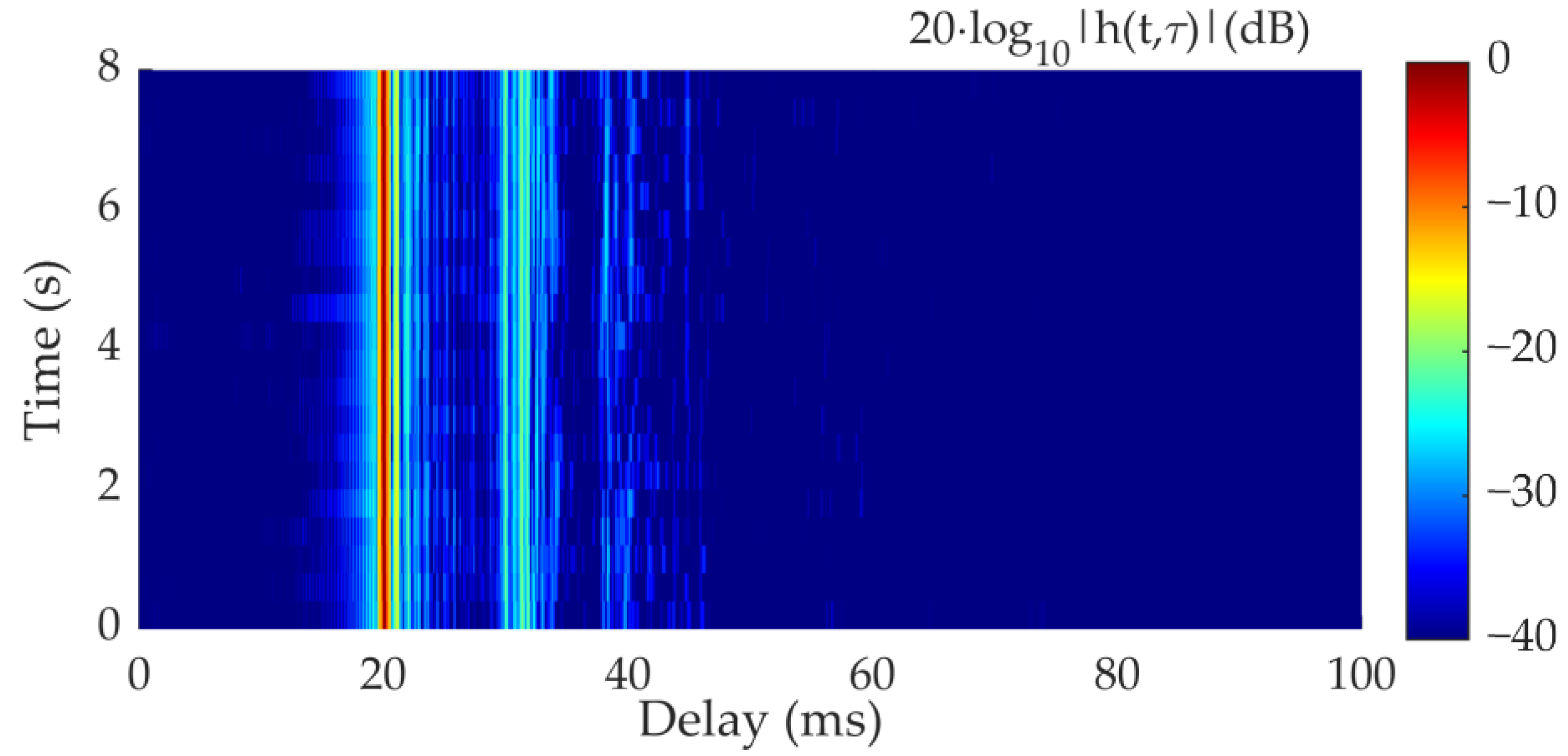
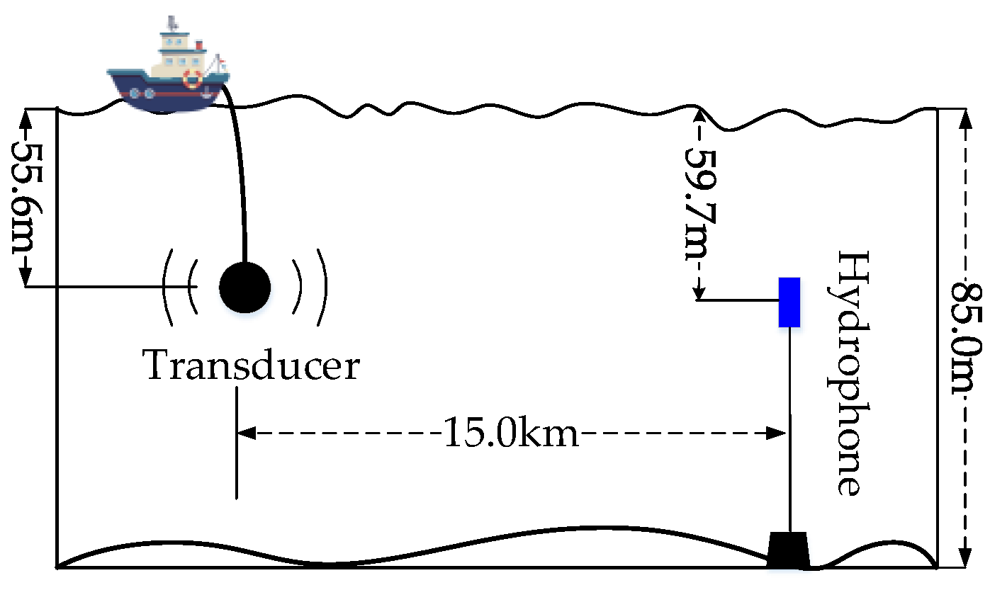
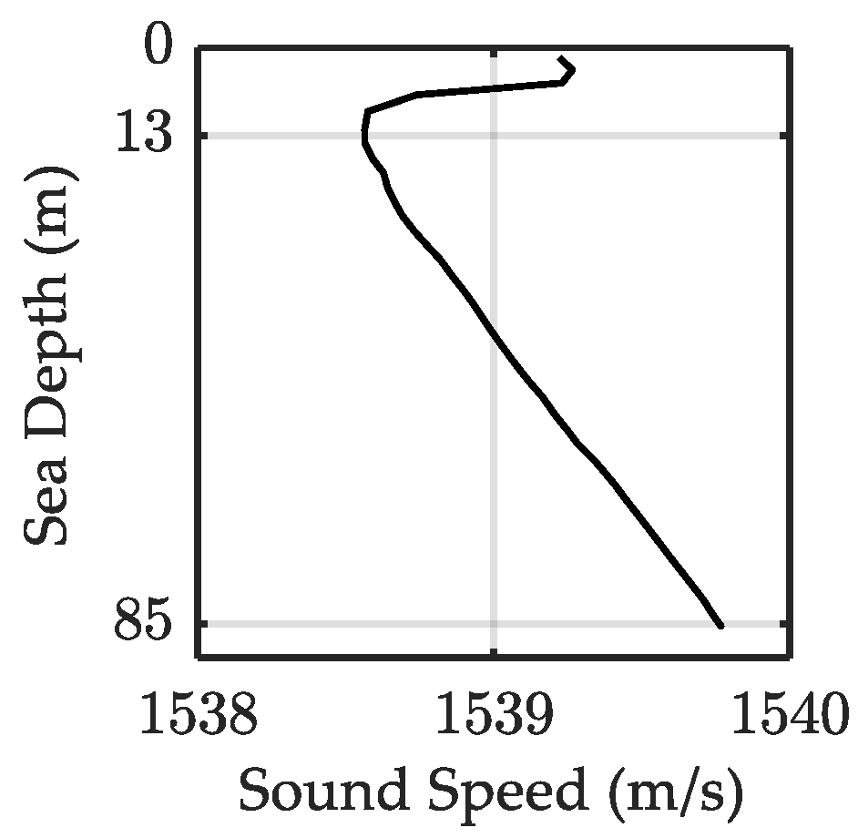
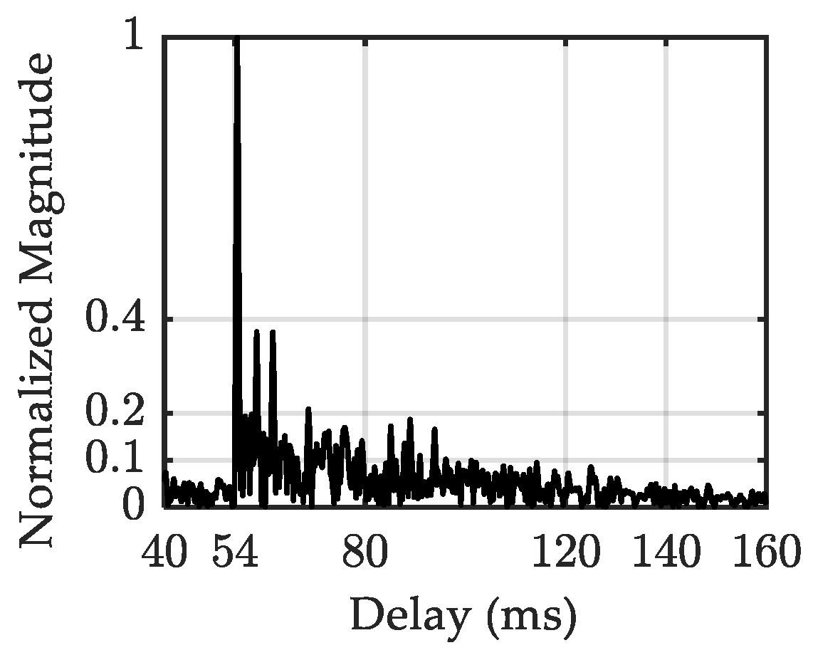
4. Sea Trial Results

To verify the actual performance of the studied CUAC scheme, a sea trial was conducted in the shallow water of the South China Sea in November 2021. The equipment layout, such as the transducer and hydrophone, is shown in Figure 9. The sea depth is approximately 85 m, and the depths of the transducers and hydrophones are 55.6 and 59.7 m, respectively. The distance between the transmitter and receiver is 15.0 km. During the sea trial, the ship drifted at 0.2–0.5 m/s.
Figure 10 shows that the variation in the measured sound velocity is small, ranging from 1538.5 to 1539.8 m/s. Figure 11 is a measured channel with a delay spread of approximately 30 ms.
The frame structure of the transmitted signals is shown in Figure 12, and each frame contains two covert communication signals with QPSK symbols. Both signals are generated by two different initial signals, which were recorded from a sea trial. The initial signals are uniformly divided into four segments, and the information phases are placed in ϕ 2 and ϕ 1 . Among them, the transmission symbol sequences of the first and second communication signals are [1,1;−1,−1] and [1,−1;−1,1], respectively.
When N = 4, there are 16 different combinations of symbol sequences, and each symbol sequence corresponds to a rotation phase combination ϕ . Similarly, the receiver performs the steganography processes with 16 rotation phase combinations on the received signal. Table 3 lists the 16 symbol sequence combinations ϕ and their indexes. The transmission symbol sequences by the two communication signals are the 4th and 7th, respectively. The demodulation is performed according to the procedure in Figure 1 and summarized steps above.
The initial signal is recorded from a sea trial. Comparing both the frequency domain of both the initial signal and transmitted signal, as shown in Figure 13, we can see that the transmitted signal has a similar spectrum with the initial signal. In addition, Figure 14 shows both the waveform and time–frequency spectrum of a received signal with an SNR of −4 dB, and the communication signal appears in the range of 0 to 2 s. We can see that the communication signal is well submerged in the ambient noise. In addition, with the advantage of non-repetitive features, communication activities can be well hidden.
To reduce the SNR to different values, different marine ambient noises were added to the received signals measured from the sea trial. When the SNR reduces to –4 dB, the receiver uses 15 steganography operations to process the received signal. The demodulation results of the two communication signals are shown in Figure 15. First, the output values of both are odd symmetric, with an “index” of 8.5, such as the eighth and ninth values.
In the two subgraphs of Figure 15, the red mark represents the index of the symbol sequence decided by the receiver, corresponding to the symbol sequences [1,1;−1,−1] and [1,−1;−1,1], respectively, and both are consistent with the transmission symbol sequences. The values with green marks are opposite to the red marks. Assuming that only the steganography operations with the 9–16th rotation phase combinations are used to obtain the last eight demodulation values, the receiver can still make an accurate decision. Taking the left subgraphs as an example, among the 9–16th demodulation values, the 13th value has the largest absolute value, but its polarity is negative. According to the odd symmetry, the correct symbol sequence index is 4. Thus, the full- and semi-search methods are equivalent. In addition, the semi-search method can greatly reduce the correlation times.
Two subgraphs in Figure 16 present the 2D search results of two communication signals of one frame, respectively, in which the receiver demodulates with the fourth and seventh steganography operations, respectively. The peak positions in the left and right subgraphs are 0.1 and 1.1 s, respectively, and the interval is 1 s, which is consistent with the signal duration. Figure 17 shows the output using the sixth rotation phase combination, and no obvious peak value exists when the adopted steganography operation does not match the transmission symbol sequence.
Next, the SNR of the received signal was reduced to different values, and the communication performance of the studied CUAC scheme was analyzed in the actual sea trial using Monte Carlo simulations. The BER curve is shown in Figure 18. When SNR = −4 dB, BER is approximately 5 × 10⁻⁴, and the rate is 4 bps.

5. Discussion

In this study, the studied CUAC scheme adopts steganography to eliminate detectable and repetitive features in communication signals. The relationship between the demodulation value and the steganographic parameters was derived, and the OMPS was obtained to improve performance. According to the odd symmetry of the demodulation value, a semi-search method is proposed to reduce the calculation cost by half and does not degrade the demodulation performance. The sea trial results show that when the SNR = −4 dB, the BER is approximately 5 × 10⁻⁴. In addition, various detection or estimation methods are applied to verify that there are no detectable features. The studied CUAC scheme can be seen as a way to realize extremely covert communication activity.
There are two aspects for improvement in the studied CUAC scheme: difficulty in estimating the channel parameters and the low transmission rate. As the demodulation is only based on a received signal without knowing the transmitted waveforms, both the received signal and intermediate signal for correlation are polluted by interference noise, which limits the communication performance. When the channel is too serious, lacking channel knowledge may lead to unsatisfactory correlation results. But the studied CUAC is still suitable for some specific scenarios, such as covert controlling command and information transmission for very hidden and long-term working platforms.

Author Contributions

Conceptualization, B.L. and J.H.; methodology, B.L. and J.H.; software, B.L.; validation, B.W. and N.J.; formal analysis, S.G.; investigation, J.H.; resources, B.L.; data curation, B.L. and N.J.; writing—original draft preparation, B.L.; writing—review and editing, N.J. and J.H.; visualization, B.W.; supervision, S.G.; project administration, B.W.; funding acquisition, B.W. All authors have read and agreed to the published version of the manuscript.

Funding

This work was supported by the National Natural Science Foundation of China under Grant 52071164.

Institutional Review Board Statement

Not applicable.

Informed Consent Statement

Not applicable.

Data Availability Statement

Data are obtained within the article.

Acknowledgments

We would like to thank all the members that participated in the sea trial. The authors would like to thank the reviewers and editors for their selfless help to improve our manuscript.

Conflicts of Interest

The authors declare no conflicts of interest.

References

  1. Lynch, R.S.; Willett, P.K.; Reinert, J.M. Some analysis of the LPI concept for active sonar. IEEE J. Ocean. Eng. 2012, 37, 446–455. [Google Scholar] [CrossRef]
  2. Fang, X.J.; Zhang, N.; Zhang, S.; Chen, D.J.; Sha, X.J.; Shen, X.M. On physical layer security: Weighted fractional Fourier transform based user cooperation. IEEE Trans. Wirel. Commun. 2017, 16, 5498–5510. [Google Scholar] [CrossRef]
  3. Ling, J.; He, H.; Li, J.; Roberts, W. Covert underwater acoustic communications. J. Acoust. Soc. Am. 2010, 128, 2898–2909. [Google Scholar] [CrossRef] [PubMed]
  4. Soltani, R.; Goeckel, D.; Towsley, D.; Bash, B.A.; Guha, S. Covert wireless communication with artificial noise generation. IEEE Trans. Wirel. Commun. 2018, 17, 7252–7267. [Google Scholar] [CrossRef]
  5. Kalinin, V.I. Wireless secure communications using UWB noise waveforms with code spectrum modulation. In Proceedings of the 2010 5th International Conference on Ultrawideband and Ultrashort Impulse Signals, Sevastopol, Ukraine, 6–10 September 2010; pp. 165–167. [Google Scholar]
  6. Watson, D.; Couto, D.J.; Beaudeau, J.P. Low probability of exploitation waveform design using Barankin bound formulation 2018. In Proceedings of the IEEE Military Communications Conference, Los Angeles, CA, USA, 29–31 October 2018; pp. 1–6. [Google Scholar]
  7. Yang, T.C.; Yang, W.B. Low probability of detection underwater acoustic communications using direct-sequence spread spectrum. J. Acoust. Soc. Am. 2008, 124, 3632–3647. [Google Scholar] [CrossRef]
  8. Yang, T.C.; Yang, W.B. Performance analysis of direct-sequence spread-spectrum underwater acoustic communications with low signal-to-noise-ratio input signals. J. Acoust. Soc. Am. 2008, 123, 842–855. [Google Scholar] [CrossRef]
  9. Shu, X.J.; Wang, J.; Wang, H.B.; Yang, X.X. Chaotic direct sequence spread spectrum for secure underwater acoustic communication. Appl. Acoust. 2016, 104, 57–66. [Google Scholar] [CrossRef]
  10. Leus, G.; van Walree, P.A. Multiband OFDM for covert acoustic communications. IEEE J. Sel. Areas Commun. 2008, 26, 1662–1673. [Google Scholar] [CrossRef]
  11. Leus, G.; van Walree, P.A.; Boschma, J.; Fanciullacci, C.; Gerritsen, H.; Tusoni, P. Covert underwater communications with multiband OFDM. In Proceedings of the OCEANS 2008, Quebec City, QC, Canada, 15–18 September 2008; pp. 1–8. [Google Scholar]
  12. van Walree, P.A.; Sangfelt, E.; Leus, G. Multicarrier spread spectrum for covert acoustic communications. In Proceedings of the OCEANS 2008, Quebec City, QC, Canada, 15–18 September 2008; pp. 1–8. [Google Scholar]
  13. van Walree, P.A.; Leus, G. Robust underwater telemetry with adaptive turbo multiband equalization. IEEE J. Ocean. Eng. 2009, 34, 645–655. [Google Scholar] [CrossRef]
  14. Liu, S.Z.; Qiao, G.; Ismail, A. Covert underwater acoustic communication using dolphin sounds. J. Acoust. Soc. Am. 2013, 133, EL300–EL306. [Google Scholar] [CrossRef]
  15. Liu, S.Z.; Ma, T.L.; Qiao, G.; Ma, L.; Yin, Y.L. Biologically inspired covert underwater acoustic communication by mimicking dolphin whistles. Appl. Acoust. 2017, 120, 120–128. [Google Scholar] [CrossRef]
  16. Jiang, J.J.; Wang, X.Q.; Duan, F.J.; Fu, X.; Yan, H.; Hua, B. Bio-inspired steganography for secure underwater acoustic communications. IEEE Commun. Mag. 2018, 56, 156–162. [Google Scholar]
  17. Jiang, J.J.; Li, C.Y.; Wang, X.Q.; Sun, Z.B.; Fu, X.; Duan, F.J. Covert underwater communication based on combined encoding of diverse time-frequency features of sperm whale clicks. Appl. Acoust. 2021, 171, 107600. [Google Scholar] [CrossRef]
  18. Li, C.Y.; Jiang, J.J.; Wang, X.Q.; Sun, Z.B.; Li, Z.C.; Fu, X.; Duan, F.J. Bionic covert underwater communication focusing on the overlapping of whistles and clicks generated by different cetacean individuals. Appl. Acoust. 2021, 183, 108279. [Google Scholar] [CrossRef]
  19. Yang, S.F.; Guo, Z.Y.; Jia, N.; Guo, S.M.; Xiao, D.; Huang, J.C.; Chen, G. Orthogonal frequency division multiplexing cyclic shift keying spread spectrum camouflaging underwater acoustic communication with dolphin whistles as information carrier. ACTA Acoust. 2018, 43, 753–761. [Google Scholar]
  20. Zhang, Z.P.; Qu, Y.; Wu, Z.Q.; Nowak, M.J.; Ellinger, J.; Wicks, M.C. RF steganography via LFM chirp radar signals. IEEE Trans. Aerosp. Electron. Syst. 2018, 54, 1221–1236. [Google Scholar] [CrossRef]
  21. Picinbono, B.; Devaut, P. Optimal linear-quadratic systems for detection and estimation. IEEE Trans. Inf. Theory 1988, 34, 304–311. [Google Scholar] [CrossRef]
  22. Gardner, W.A. Cyclostationarity in Communications and Signal Processing; Statistical Signal Processing Inc.: Yountville, CA, USA, 1994. [Google Scholar]
  23. Jang, W.W.; Lee, W.J. Detecting wireless steganography with wavelet analysis. IEEE Wirel. Commun. Lett. 2021, 10, 383–386. [Google Scholar] [CrossRef]
  24. Gardner, W.A. Signal interception: A unifying theoretical framework for feature detection. IEEE Trans. Commun. 1988, 36, 897–906. [Google Scholar] [CrossRef]
  25. Punchihewa, A.; Zhang, Q.; Dobre, O.A.; Spooner, C.; Rajan, S.; Inkol, R. On the cyclostationarity of OFDM and single carrier linearly digitally modulated signals in time dispersive channels: Theoretical developments and application. IEEE Trans. Wirel. Commun. 2010, 9, 2588–2599. [Google Scholar] [CrossRef]
  26. Wu, Z.Q.; Yang, T.C. Blind cyclostationary carrier frequency and symbol rate estimation for underwater acoustic communication. In Proceedings of the 2012 IEEE International Conference on Communications, Ottawa, ON, Canada, 10–15 June 2012; pp. 3482–3486. [Google Scholar]
  27. Fehske, A.; Gaeddert, J.; Reed, J.H. A new approach to signal classification using spectral correlation and neural networks. In Proceedings of the First IEEE International Symposium on New Frontiers in Dynamic Spectrum Access Networks, Baltimore, MD, USA, 8–11 November 2005; pp. 144–150. [Google Scholar]
  28. Like, E.; Chakravarthy, V.D.; Ratazzi, P.; Wu, Z.Q. Signal classification in fading channels using cyclic spectral analysis. EURASIP J. Wirel. Commun. Netw. 2009, 1–14. [Google Scholar] [CrossRef]
  29. Xu, Z.J.; Gong, Y.; Wang, K.; Lu, W.D.; Hua, J.Y. Covert digital communication systems based on joint normal distribution. IET Commun. 2017, 11, 1282–1290. [Google Scholar] [CrossRef]
  30. Cek, M.E. Covert communication using skewed α-Stable distributions. Electron. Lett. 2015, 51, 116–118. [Google Scholar] [CrossRef]
  31. Xu, Z.J.; Jin, W.B.; Zhou, K.; Hua, J.Y. A covert digital communication system using skewed α-stable distributions for internet of things. IEEE Access 2020, 8, 113131–113141. [Google Scholar] [CrossRef]
  32. Cek, M.E. M-ary alpha-stable noise modulation in spread-spectrum communication. Fluct. Noise Lett. 2015, 14, 1550022. [Google Scholar] [CrossRef]
  33. Xu, Z.J.; Wang, K.; Gong, Y.; Lu, W.D.; Hua, J.Y. Structure and performance analysis of an SαS-based digital modulation system. IET Commun. 2016, 10, 1329–1339. [Google Scholar] [CrossRef]
  34. Park, J.D.; Doherty, J.F. A steganographic approach to sonar tracking. IEEE J. Ocean. Eng. 2019, 44, 1213–1227. [Google Scholar] [CrossRef]
  35. Petitcolas F.A., P.; Anderson, R.J.; Kuhn, M.G. Information hiding-a survey. Proc. IEEE 1999, 87, 1062–1078. [Google Scholar] [CrossRef]
  36. Passerieux, J.M. Stealth underwater acoustic communications based upon steganography techniques, 2014. In Proceedings of the 2nd International Conference and Exhibition on Underwater Acoustics, Rhodes, Greece, 22–27 June 2014; pp. 1199–1206. [Google Scholar]
  37. Kemerait, R.; Childers, D. Signal detection and extraction by cepstrum techniques. IEEE Trans. Inf. Theory 1972, 18, 745–759. [Google Scholar] [CrossRef]
  38. Van Walree, P.A.; Jenserud, T. A discrete-time channel simulator driven by measured scattering functions. IEEE J. Sel. Areas Commun. 2008, 26, 1628–1637. [Google Scholar] [CrossRef]
Figure 1. Operation of resampling to obtain correlation value.
Jmse 12 02217 g001
Figure 2. CS of wideband ocean ambient noise (left), transmitted CUAC signal (middle) and DSSS signal (right).
Jmse 12 02217 g002
Figure 3. NMSE of SFDM and CS analysis vs. SNR.
Jmse 12 02217 g003
Figure 4. Cepstrums of four transmitted signals with duration of 0.2555 s and four waveforms are different.
Jmse 12 02217 g004
Figure 5. Cepstrums of four DSSS and four transmitted signals with duration of 0.2555 s and four waveforms are same.
Jmse 12 02217 g005
Figure 6. NMSE of symbol duration estimation using cepstrum for both DSSS and transmitted signals.
Jmse 12 02217 g006
Figure 7. Simulation channel measured from a sea trial.
Jmse 12 02217 g007
Figure 8. BER for different T x and N with demodulation of full- and semi-search methods.
Jmse 12 02217 g008
Figure 9. Setup of sea trial equipment.
Jmse 12 02217 g009
Figure 10. Measured Sound speed profile.
Jmse 12 02217 g010
Figure 11. Measured channel.
Jmse 12 02217 g011
Figure 12. Frame structure of CUAC transmission signal.
Jmse 12 02217 g012
Figure 13. The frequency domain of initial signal and transmitted signal.
Jmse 12 02217 g013
Figure 14. The waveform (up) and time–frequency spectrum (down) of a received signal with SNR of about −4 dB.
Jmse 12 02217 g014
Figure 15. Demodulation values of the first (left) and second (right) received signal in one frame using different ϕ , and the red and green marks mean the maximum values with opposite polarity.
Jmse 12 02217 g015
Figure 16. Demodulation value of time–frequency search by the 4th and 7th steganography operation for first (left) and second (right) received signal in one frame, respectively.
Jmse 12 02217 g016
Figure 17. Demodulation value of time–frequency search by the 6th steganography operation for first and second received signal.
Jmse 12 02217 g017
Figure 18. BER curve obtained from sea trial data by adding interference noise.
Jmse 12 02217 g018
Table 1. Environmental parameters of measured channel used for simulation.
Sea DepthRangeTx DepthRx DepthFrequency
163.0 m5.0 km63.0 m80.0 m4–8 kHz
Table 2. Simulation setting.
T x (s) N T n (s)
Semi-search120.5
Semi-search140.25
Full/Semi-search221
Full/Semi-search240.5
Table 3. Index of symbol sequence when N = 4.
IndexSymbol SequenceIndexSymbol Sequence
1[1,1;1,1]9[−1,1;1,1]
2[1,1;1,−1]10[−1,1;1,−1]
3[1,1;−1,1]11[−1,1;−1,1]
4[1,1;−1,−1]12[−1,1;−1,−1]
5[1,−1;1,1]13[−1,−1;1,1]
6[1,−1;1,−1]14[−1,−1;1,−1]
7[1,−1;−1,1]15[−1,−1;−1,1]
8[1,−1;−1,−1]16[−1,−1;−1,−1]
Disclaimer/Publisher’s Note: The statements, opinions and data contained in all publications are solely those of the individual author(s) and contributor(s) and not of MDPI and/or the editor(s). MDPI and/or the editor(s) disclaim responsibility for any injury to people or property resulting from any ideas, methods, instructions or products referred to in the content.

