Abstract
Whale signals originating in the vicinity of a triplet of underwater hydrophones, at a 2 km distance from each other, are recorded at the three sensors. They offer the opportunity to test simple models of propagation applied in the immediate neighborhood of the triplet, by comparing the arrival times and amplitudes of direct and reflected paths between the whale and the three hydrophones. Examples of recordings of individual fin whales passing by hydrophone triplets, based on the characteristics of their vocalizations around 20 Hz, are presented. Two types of calls are observed and their source wavelets extracted. Time segments are delimited around each call using a power detector. The time of arrival of the direct wave to the sensor and the Time Differences of Arrivals (TDOA) between sensors are obtained by correlation of the extracted source wavelets within the time segments. In addition to direct arrival, multiple reflections and the delays between the reflection and the direct arrival are automatically picked. A grid-search method of tracking the calls is presented based on the TDOA between three hydrophones and reflection delay times. Estimates of the depth of vocalization of the whale are made assuming a simple straight ray propagation model. The amplitude ratios between two hydrophones follow the spherical amplitude decay law of one over distance when the cetacean is in the immediate vicinity of the triplet, in a circle of radius 1.5 km sharing its center with the triplet’s center.
1. Introduction
Whale songs are frequently recorded on the hydrophones of the International Monitoring System (IMS) hydroacoustic network of the Comprehensive Nuclear-Test-Ban Treaty Organization (CTBTO) [1]. The larger whales such as blue whales—Balaenoptera musculus—and fin whales—Balaenoptera physalus—emit acoustic energy in the [15–50] Hz frequency range [2], which can be used to assess the suitability of simple ocean–acoustic wave propagation models to estimate the location of the whales. There is a large body of literature about fin whale observations and vocalizations. Initial observations were made over the course of several decades starting in the early 1960s, using different hydrophone configurations, including multiple towed hydrophones [3]. Questions remain such as the depth at which they emit the sound; if they emit the sound when only at certain depths; the number of animals emitting at the same time; the depth-dependent interference of the direct signal with the surface reflection; the possible frequency- and depth- dependent radiation pattern of the acoustic emission; etc. This study estimates the range and depth from recordings of large-amplitude signals in the proximity of one hydrophone IMS station.
The locations of all IMS stations [4], including the hydroacoustic stations, are openly available. Five of the six hydrophone IMS stations consist of pairs of triplets of hydrophones close to oceanic islands. These island stations have one triplet deployed to the north and the other to the south of the island with hydrophone deployment depths close to the generally considered depth of the Sound Fixing and Ranging (SOFAR) channel [5] of 700 m to 1000 m. The depths at which the hydrophones are deployed provide excellent detection capabilities for hydroacoustic signals originating from very far distances of thousands of kilometers and trapped in the SOFAR channel. The acquisition system of the hydrophones has a sampling frequency of 250 Hz. A filter is applied to the data compensating for the system response that makes the data above 100 Hz difficult to use as calibrated data. Less relevant to the study in this paper, the acquisition system also has limitations on the lower frequency end. This still allows recordings of signals almost undisturbed between 1 and 100 Hz. This bandwidth is mandated by Member States of the CTBTO [1] as specifications for the IMS hydrophones in the Operational Manual for Hydroacoustic Stations developed as required by the CTBT.
Previous works were concerned with whale tracking methods for basic understanding of animal behavior and mitigation of seismic air gun surveys on the animals. For instance, methods have been developed to estimate the depth of a diving sperm whale—Physeter macrocephalus—from the time difference between the direct arrival and the surface reflection, using two or three elements vertical or horizontal hydrophone arrays [6]. Triangulation has been used to track the diving behavior of bowhead whales—Balaena mysticetus—in the noisy environment of a seismic air gun survey [7]. In both these examples, the signals emitted by the animal cover higher frequencies ([5–20] kHz) and short duration (<25 ms) for sperm whales, and [0.2–2] kHz for bowhead whales. These higher frequencies are above the useful frequency range of the IMS hydrophones, and the present work studies signals emitted by likely fin whales, at frequencies below 0.1 kHz. Whale tracking has also been used to compare the source level (SL) of fin whale signals recorded at an in-water hydrophone location in the Pacific Ocean and an Ocean Bottom Seismometer (OBS) in the Atlantic Ocean [8]. Parabolic equation modeling is the central tool used to derive the SL of fin whales in the two regions [9].
Other works do not specifically track whales but rather use characteristics of their calls and spatial and temporal statistics of the calls, for instance to obtain information on the population of blue whales in the southeast Indian Ocean and southwest Pacific Ocean [10]. Temporal statistics have put in evidence that the dominant frequency of pygmy blue whales decreases with time over a period of 8 years [11], and that their range of detectability is between 50 km and 200 km from the HA01 triplet [12]. A range estimate of up to several tens of kilometers from the northern triplet of HA08 for blue whales in the Chagos archipelago in the Indian Ocean was obtained using a method based on two parameters: back-azimuth estimates using the signals on the three hydrophones and amplitude decay estimates [13]. At these distances, based on modeling up to signal propagation ranges of 250 km, the amplitude of the whale signal decays roughly like the inverse of the square root of the distance to the hydrophone, as expected from a cylindrical geometrical spreading. The blue whale calls were detected in records from January 2003 with a Short-Term Average/Long-Term Average (STA/LTA) method using a threshold of 2.5.
At closer range, it is possible to use the Time Differences of Arrivals (TDOA) between the three hydrophones to estimate the location of the calls; however, the depth resolution is poor. For further ranges, only the direction of the incoming signals is available. A grid-search method was used to trace the path of a likely fin whale crossing the waters above hydrophone station HA01, Cape Leeuwin, Australia [14]. In that work, the authors tracked the movement of the whale through the three hydrophones using the direct arrival from the whale signal and assuming a shallow depth. They also observed multiple scattered energetic arrivals—one directly from the ocean bottom, another from the sea surface after reflection from the ocean bottom—as the whale position was close to being in the area directly above the hydrophones. Similar multiple scattered arrivals from the bottom and sea surface had previously been observed in bottom-moored hydrophones in the Southern Ocean [15]. In addition to water multiple reflections, crustal reflections were observed from fin whale calls recorded on ocean bottom seismometers (OBSs) in the straights of Juan de Fuca, between the USA and Canada [16].
Tagged animal studies on fin and blue whales [17] have been conducted and show some variability in the swimming depth of a fin whale between very shallow depth (10 m) and up to nearly 300 m. A deeper dive may occur amidst shallower ones. At shallow depths of vocalization of a fin whale, somewhere between the sea surface and 300 m depth, it may be difficult to differentiate in time between the direct path from the animal to the hydrophone, and the reflection from the sea surface. In [13], a double peak in the autocorrelation and envelope of the first arrival may hint at this sea surface reflection. An elaborate approach [18] based on modeling Lloyd’s mirror effect [19] estimated the depth of vocalizing fin whales using the hydrophone and vertical component seismometer channels of OBSs and estimated a depth of 72 m in one of the examples. A shallow depth of 15 m was also estimated, for an individual fin whale localization, based on the modeling of travel times of multiple bottom and surface reflections, at the three hydrophones of the southern triplet of IMS hydroacoustic station HA11 [20].
The purpose of this paper is to develop a method to track and locate whales emitting low-frequency ([1–100] Hz) sounds, such as blue whales and fin whales, recorded on the existing deployed hydroacoustic network of the IMS sensor network. Because of the frequency bandwidth of the recordings, it is a challenge to separate arrivals in the time domain when they are close together, as is the case for the direct arrival and the surface reflection if the animal is close to the surface. It may be possible to gain information in the frequency domain, together with the three distances to the hydrophones, i.e., the Lloyd’s mirror where the separation of fringes at a particular frequency depends on the distance of the source to the sea surface.
The advantages of the IMS network are its quality, thanks to the calibration of the data, its spatial coverage, continuous acquisition system, and potential for automatic processing, for instance detecting specific features in the signal. In the present work, data processing and location methods are applied to a data set recorded at hydrophone triplet H11S, on 19 and 20 February 2024. A fin whale passed close to the triplet, similarly to the 26 July 2017 at HA01 [14], and the multiple passages at HA11, between 2010 and 2022 in [20].
An initial power detector is first used to identify the most energetic arrivals corresponding to the direct arrivals of the whale calls and a time segment extracted around each detected arrival. Source wavelets of the acoustic signal emitted by the animal are then extracted using a stacking algorithm. Cross-correlating the source wavelet with the time segments around each direct arrival pick leads to an accurate picking of the direct arrivals and a separation of this direct arrival from later reflections within each segment. A grid-search localization method is then presented and applied with the TDOAs and time delays from two reflections. We believe that the innovative approaches in this work include the source wavelet extraction which allows for accurate automatic time picking on the envelope of the cross correlation of the raw data with the source wavelet. Another innovation is to use the amplitude ratios of the direct arrivals between hydrophones to confirm the expected results from the locations, carried out via time picks.
2. Data Acquisition and Processing Methods
2.1. Data Acquisition
The data set analyzed in this work was acquired at IMS hydroacoustic stations HA11. Table 1 shows basic site location parameters for the hydrophones H11S1, H11S2, and H11S3 of the southern triplet of the station. For the remainder of this work, the identifiers S1, S2, and S3, as shown in Table 1, will be used for, respectively, H11S1, H11S2, and H11S3. A local coordinate system has the S1 hydrophone location as its origin and Table 1 also shows the coordinates of the hydrophones in this local system. Figure 1d is a simple local map showing the geometry of the triplet.

Table 1.
Basic geometry parameters for HA11S triplet. The nominal water depth is 1174 m.
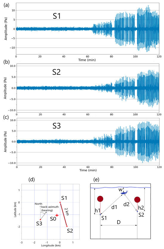
Figure 1.
(a–c) show two hours of unfiltered hydrophone data starting at 21:00 UTC on 19 February 2024 for, respectively, the S1, S2, and S3 hydrophones. Around the one-hour mark, frequent (approximately once every 25 s) impulsive signals are visible and increasing in amplitude towards the end of the section. The amplitudes are in Pa. (d) A basic map with the S1 hydrophone being the origin of the local horizontal coordinate system. S0 marks the center of the triplet and the arrow next to S3 shows how the back-azimuth is measured from the north. The latitude and longitude differences are in kilometers. The absolute latitude and longitude of the S1 hydrophone are, respectively, 15.50827 degrees north and 166.700272 degrees east. (e) Vertical geometry in a cross-section including hydrophones S1 and S2 and defines parameters used in the text. The whale may or may not be in the same vertical plane as hydrophones S1 and S2.
The data are openly available from the IRIS data center [21] with network code IM. Figure 1a–c show two hours of three traces at, respectively, hydrophones S1, S2, and S3 at the beginning of the sequence of interest, starting at 21:00 UTC on 19 February 2024. The data acquisition and most signal processing performed in this work used the ObsPy software library, version 1.4.2 [23], used in the context of either the Google Colaboratory [24], or the Jupyter Lab [25] environments. The data of interest is clearly visible on the raw waveform starting at around 22:05 UTC on 19 February 2024, sixty-five minutes after the beginning of the trace. Several observations can be made regarding the features of the signal on the three waveforms:
- The amplitude of the signal is increasing on all three waveforms starting from about one hour after time zero. This can easily be explained if the source is progressively getting closer to all three sensors until the end of the two-hour sequence.
- The amplitudes at hydrophones S1 and S3 are slightly higher than at hydrophone S2.
- There appear to be interruptions of two to three minutes in the sequence of calls every fifteen to twenty minutes. Since it is well known that cetaceans surface at regular intervals to breathe, it seems natural to infer that these short interruptions correspond to the surfacing of a single individual, or several individuals surfacing in a synchronized fashion, and that the vocalizations happen while the animal dives between the surfacing. This pattern has previously been observed and the two-to-three-minute interruptions attributed to the surfacing of the animal [17,26].
On the spectrogram for the same time interval, the beginning of the trace also shows the large amplitude individual transient arrivals in the [15–50] Hz band. This is illustrated by Figure 2 showing the first and last 30 min of the two-hour interval. Observations beyond the previous ones can be made from the spectrograms:
- Two types of calls are clearly visible on the spectrogram. One type has a broader bandwidth of [17–40] Hz and higher center frequency than the other one ([15–25]) Hz. Nomenclature type A for the lower frequency type and type B for the higher frequency have previously been used in the literature and will be used in the remainder of this paper [19]. The two types are separated by about 25 s, and generally alternate, but not always. Exceptions can be seen in Figure 2 just after the 5400 s mark with three consecutive type A calls, then in an interval of about 100 s after 5600 s with three consecutive type A in that interval, and again twice at about 5800 s. Each call is picked individually, and the measurement of amplitudes shows a bimodal distribution corresponding to these two types.
- If the hypothesis that the interruptions in the calls are at the time of surfacing, and the calls originate with a single individual, the first call when the animal dives is generally the lower, narrower band, frequency pulse (type A), and the last call is the higher, broader band, frequency call (type B).
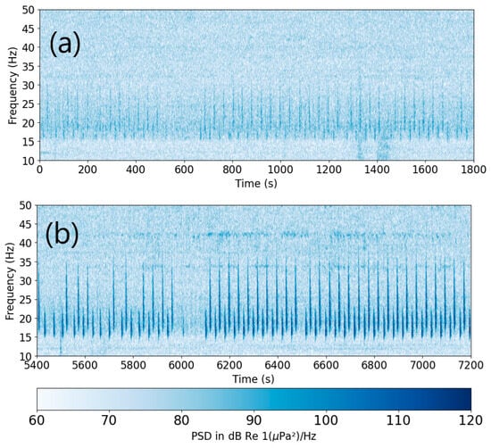
Figure 2.
Spectrograms of the first 30 min (a), and the last 30 min (b) of the two hours of waveforms for S2 shown in Figure 1. An FFT length of 1024 points with 512 points overlap was used to compute the whole spectrogram over the entire 7200 s duration. The first 30 min and last 30 min were then windowed. The Nyquist frequency is 125 Hz. The frequency resolution is 0.244 Hz (512 intervals in [0–125] Hz) and the time resolution is 2.05 s.
A large data set at the triplet was acquired between 18:00 UTC on the 19 February and 16:00 UTC on the 20 February 2024. Visual analysis concluded that the large amplitude calls started after 21:00 UTC on the 19 February. They lasted at least until 07:30 UTC on the 20 February, and all analysis conducted in this paper takes place between these times. In the remainder of this work, to avoid repeating the date too often, the date is omitted and only the time mentioned, since after 21:00 UTC on the 19th and before 07:30 UTC on the 20th, the date is unambiguous.
2.2. Waveform Signal Processing
2.2.1. Power Detector for Individual Calls
To estimate the location of the whale calls when the signal is strong, we start by picking individual signals out of the background noise using the STA/LTA ratio method, explained in [27]. This method is often applied on seismic data (e.g., [28]) for the purpose of automatic picking of seismic phases. In the present work, the STA time interval is 0.1 s and the LTA time interval 1 s. This method is also part of the hydroacoustic processing chain at the International Data Centre (IDC) of the CTBTO, as explained in detail in [29]. In the present work, the STA/LTA method is applied to raw data after removal of a linear trend. If nsta is the number of samples in the STA interval and nlta the number of samples in the LTA interval, the power detector STA/LTA trace, Pd, is computed as , where W is the waveform. The use of the STA/LTA trigger algorithm is limited to finding large SNR transient signals and delimiters for time segments following these signals. Further processing is performed on the segments to first extract the source signal and then use this source signal to cross-correlate with the segment and identify multiple arrivals within the segment.
This is illustrated by Figure 3 where values of 6 for the trigger-on and 5 for trigger-off are used on a five-minute interval of data at hydrophone S1 starting at 2:20:00 UTC. Fifteen detections are made in the time interval. Segments start 2.5 s before the trigger-on time of the hydrophone S1 detection and are 10 s long. This margin of 2.5 s is used to ensure that signals from the same call recorded at the three hydrophones will be contained within the same 10 s segment in absolute time. Figure 3a shows a close-up of the segment extracted around the first call in the sequence, which is identified as a type B call, based on its frequency content. The ten-second interval for that first call is shown as a gray box. Figure 3b shows the STA/LTA function for that call. For the whole five-minute time interval, the same number of detections is made on the other two hydrophones, S2 and S3. This is not always the case. Figure 3c shows the fifteen calls on hydrophone S1, with the type A or B identification placed before each call.
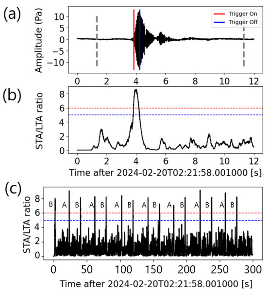
Figure 3.
Illustration of the STA/LTA detection method on a single call and on a five-minute interval at hydrophone S2. (a) The first signal with red and blue timelines show, respectively, the trigger-on and trigger-off times. Linear detrend processing is applied to the raw data before application of the power detector. The dashed, thick, gray lines are the start and end of the 10 s segment starting 2.5 s before the trigger-on time. (b) The STA/LTA function of the first signal. The timelines show the trigger-on (red) and trigger-off (blue). (c) STA/LTA of the five-minute interval with fifteen calls. Each call is labeled A or B according to its center frequency. The horizontal, dashed, red and blue lines show the trigger-on and trigger-off thresholds of 6 and 5, respectively.
2.2.2. Source Wavelet Extraction for Type A and B Calls
The source wavelets were extracted from the data within a 30 min interval starting at 22:40 UTC, using a stacking procedure. The assumption is that the direct signal from the whale arrives first at each of the hydrophones and that scattered signals arrive at different differential times after the original signal. By aligning the first breaks of the signals for all calls of each type, and stacking them all, the energy from the scattered part of the signal can be considered to arrive at random times and be identified as noise. The alignment is achieved automatically by first masking the data with a Hanning [30] window of length 1.12 s starting 2.22 s within the 10 s segment. The traces are then aligned by cross-correlating each trace with the initial trace and automatically picking the maximum of the cross-correlation. Stacking will emphasize the direct signal and extract it from the noise. This is illustrated by Figure 4 which shows the aligned waveforms at hydrophone S1, the aligned waveforms superimposed on each other, and the stack resulting in the elimination of the noisy tails after the direct signal. This method has been used successfully in seismic reflection processing to increase the signal to noise ratio of reflections. In seismic reflection, data are acquired along a line with source points moving along the line and receivers at multiple offsets. The traces are first arranged such that for a point along the line of acquisition of a survey, the traces sharing this same midpoint between source and receiver are assembled. The offset varies for each trace in that gathering and stacking are carried out after aligning the traces according to the move-out expected for the velocity at the zero-offset two-way time [31].
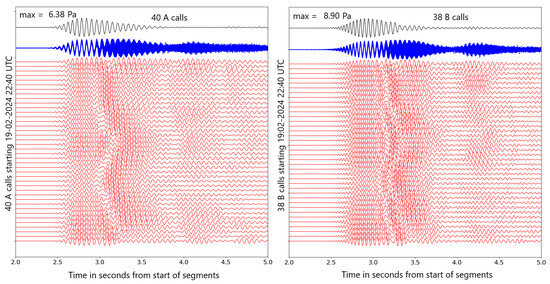
Figure 4.
Extraction of the source wavelets A and B by stacking of the time segments at hydrophone S1 after aligning them using the cross-correlation technique. This example is from a 30 min time interval starting at 22:40 UTC. The red traces are individual calls (40 A calls and 38 B calls). The blue traces are the same traces superimposed on each other. The black trace at the top is the stack for hydrophone S1.
Figure 5 reproduces the A and B wavelets extracted from the signals at hydrophones S1, S2, and S3 within the 30 min interval. The top panel shows the distinct superimposed signals in red for hydrophone S1, green for hydrophone S2, and blue for hydrophone S3. Note how similar the independently extracted signals are. The middle panel shows the average of the three. Also shown are the magnitude and phase spectra of the average signals. As expected, the B calls have broader frequency bandwidth. The A signals seem to be a bit longer in duration. Figure 6 shows the spectrogram of both signals on a synthetic trace containing both signals separated by four seconds.
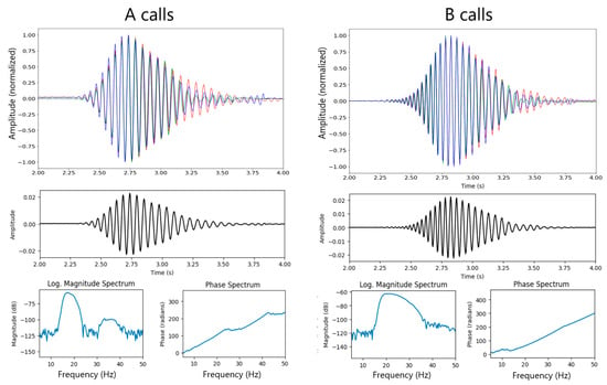
Figure 5.
Source wavelets A on the left and B on the right. The top panel shows the wavelets extracted from each of the three hydrophones: S1 in red, S2 in green and S3 in blue. These were aligned to maximize their cross-correlation and each normalized to a maximum of 1. The three stacks are then added together, and normalized such that the RMS of the resulting stack has a value of one, as shown in the middle panel. Magnitude and phase spectra are shown below each RMS-normalized source wavelet.
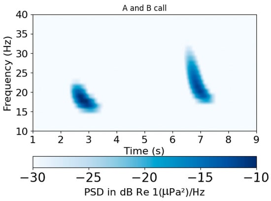
Figure 6.
A spectrogram of source wavelets A on the left and B on the right. Note the downward sweep pattern for both call types. The amplitude scale is arbitrary, as well as the time separation between the calls.
2.2.3. Picking of Direct Arrival and Multiple Reflections Using Cross-Correlation with Source Wavelets
Once the source wavelets have been extracted from the data, cross-correlating them with each eight-second segment delimited using the STA/LTA power detector will result in identifying the direct and reflected waves in each of the segments. Figure 7 illustrates the cross-correlation of the A and B wavelets on such an eight-second segment of each type. Note that the direct wave and a strong reflection following approximately half a second later dominate the signal. Several later reflections are also visible. The A and B calls are following each other in a sequence, approximately 20 s apart. Therefore, if the signals are emitted by the same animal, the locations of vocalization of the A and B calls should not be far apart, and the time sequences of multiple reflections are similar for both calls. The resolution on each arrival, however, is better for the B calls since the signal is broader band than the A calls. This is especially true for the direct arrival and first reflection which are clearly separated in the B call. This first reflection is likely the reflection from the bottom of the ocean, which would be expected to arrive at a time of about 0.6 s, corresponding approximately to twice the difference between the depth of the ocean (1174 m) and the depth of the S1 hydrophone (739 m).
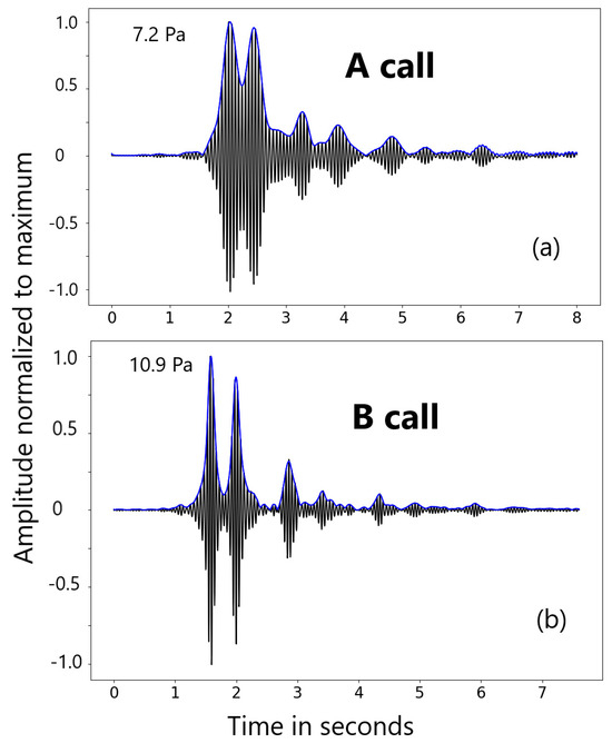
Figure 7.
Panel (a) shows the cross-correlation of the extracted A source wavelet with the first eight-second segment with an A call after 02:22 UTC on the S1 hydrophone. Panel (b) shows the cross-correlation of the extracted B source wavelet with the first eight-second segment with the first B call recorded on hydrophone S1 after the A call shown on (a). Both panels also show the envelope in blue. Traces are normalized to the maximum amplitudes, which is annotated next to the maximum of the traces.
2.2.4. Extraction of Times and Amplitudes of Arrivals
Once the envelopes of the cross-correlations have been obtained, the times and amplitudes of each major peak are automatically obtained using a custom-made recursive algorithm. In the example presented, only peaks larger than 1/8th of the maximum of the segment are considered. This results in a series of times and amplitudes for each segment as shown in Figure 8 for an eighteen-minute interval starting at 23:02 UTC.
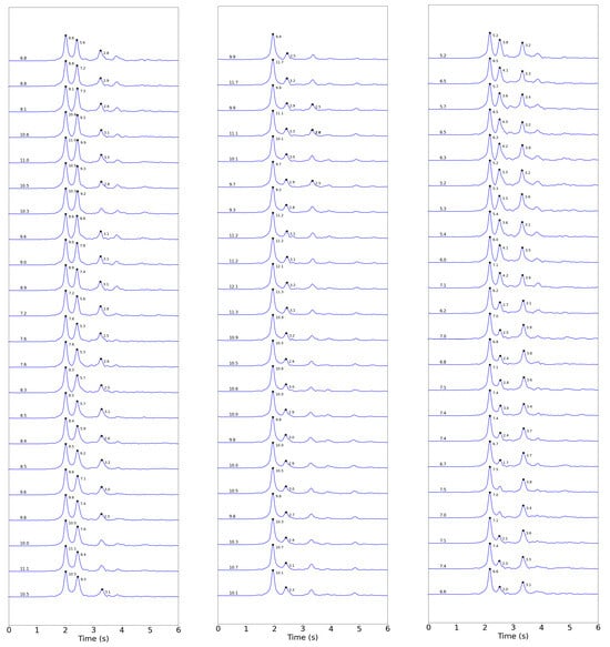
Figure 8.
Each panel shows the first 6 s of the 10-s envelopes computed on an 18-min interval after 23:02 UTC. A total of 22 B calls are recorded for hydrophones S1, S2, and S3. The time picks for each local maximum are marked with black dots and their amplitudes in Pa annotated next to them. The value of the maximum amplitude, in Pa, for each trace is also indicated above the start of the trace.
The first peak is considered to correspond to the direct arrival. The TDOAs are the differences between the time picks of that first arrival at the pairs of hydrophones. They are named d12 for the difference between the arrival time at S2 minus the arrival time at S1. Similarly, d23 and d31 are the differences between the other two pairs of hydrophones. In the remainder of this paper, TDOA refers specifically to time differences between direct arrivals at the hydrophones and not to reflected arrivals. The TDOAs extracted for a two-hour interval starting at 23:00 UTC are shown in Figure 9. The A calls in that interval number 137 and the B calls number 114.
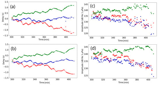
Figure 9.
(a,b) TDOAs for the A (top) and B (bottom) calls for a two-hour time interval starting at 23:00 UTC. The red dots are the TDOAs d12 between hydrophones S1 and S2, the green dots are for d23, and the blue dots for d31. The solid lines, respectively, red, blue, and green, for d12, d23, and d31, are a spline fit to the B calls TDOAs. They are reproduced on the top and bottom panels. The red, green, and blue dashed lines are shown only on the top panel and are the spine fit to the A calls TDOAs. (c,d) Amplitudes (received level in dB Re 1μPa) of direct arrivals at hydrophones S1 (red), S2 (green), and S3 (blue) for the same A (top) and B (bottom) calls as in (a,b).
Spline fits to the B calls delays are shown with solid lines (red for d12, green for d23, blue for d31) in Figure 9b. The same spline is repeated in Figure 9a showing the A calls delays, along with dashed lines which are the spline fit for the A calls delays. The same color convention for d12, d23, and d31 are used on both panels. Note how close the two lines are, the dashed lines being visible only occasionally. This is quantified by the computation of the root mean square (RMS) for each of d12, d23, and d31. The RMSs of residuals with respect to the spline derived from the B calls (solid lines) are, respectively, 0.027 s, 0.017 s, and 0.03 s for d12, d23, and d31 for the A calls and 0.009 s, 0.008 s, and 0.007 s for the B calls. For the spline derived from A calls (dashed line), the RMSs are, respectively, 0.012 s, 0.011 s, and 0.01 s for the A calls and 0.02 s, 0.014 s, and 0.02 s for the B calls. The delays calculated for the A and B calls are therefore very likely to originate from positions on the same trajectory, although the maximum RMS error of 0.03 corresponds to a distance of 45 m and it is possible that the position of two individuals is with 45 m of each other.
The preferred interpretation for the authors of this work is that the A and B calls are emitted by the same animal, contrary to the conclusion reached by authors studying fin whales at the same location [20] in 2020, who concluded that some A and B calls originated from two different animals. Some of the data used in [20] was processed using our method and the results discussed in the Supplementary Materials. Figure S1 shows the delays measured for the A and B calls for a 45 min interval starting at 02:00 on 13 February 2020. Figure S2 shows the A call located by the authors, which was found to be sufficiently far for the tracks computed from neighboring B calls that they concluded that it emanated from a different animal. This A call has a lower SNR than all the other 42 A call picks shown on Figure S1 and therefore the location obtained from it may be less reliable than for calls with higher SNR.
The amplitudes measured at the maximum of the envelopes of the first arrivals are shown in Figure 9c,d. Parameters d12, d23, and d31 and amplitudes a1, a2, and a3 are extracted from the direct arrivals. Time differences between the first reflection and the direct arrival r11, r12, and r13, as well as between the second reflection and the direct arrival r21, r22, and r23. These nine parameters constitute the input to the grid search algorithm to estimate the track of the whale. This algorithm is presented in the next Section.
A step-by-step summary of the feature extraction algorithm yielding the values of d12, d23, d31, r11, r12, r13, r21, r22, and r23 is provided in the table below (Algorithm 1):
| Algorithm 1 DTOA and amplitude extraction | |
| Input: Three waveform segments from hydrophones S1, S2, S3. Output: Three arrays of time differences d12, d23, and d31 and three arrays of amplitudes a1, a2, and a3 for each of the two types of calls identified (A and B). The three arrays of times and amplitudes have length nA for type A calls and nB for type B calls. Processing time: For a two-hour segment, on a Google backend via Colaboratory, the processing is performed in two steps (first module carries out steps 1 to 3, second carries out 3 to 5) of 59–61 s each. | |
| Step 1 | Apply STA/LTA algorithm on all three waveforms. Obtain N1, N2, and N3 detections, respectively, on hydrophones S1, S2, and S3. Identify each detection as either an A-type call or B-type call (see Figure 3). |
| Step 2 | For each detection at hydrophone S1: If detections exist for hydrophones S2 and S3, compatible with a single call detected at all three hydrophones, group them with the hydrophone S1 detection. This results in Ndet groups of three detections (one each at hydrophones S1, S2, S3) where Ndet ≤ N1. |
| Step 3 | For each 10-s segment (2.5 s before the time of the STA/LTA detection at hydrophone S1, and 7.5 s after) around each detection, cross-correlate with the source wavelet of the appropriate type and take the envelope of the resulting cross-correlation (see Figure 7). |
| Step 4 | For each envelope segment, identify peaks larger than 1/8th of the maximum amplitude with times and amplitudes of their local maximum (see Figure 8). |
| Step 5 | The TDOAs (d12, d23, d31) and amplitudes (a1, a2, a3) are, respectively, the time differences between the time picks of the first peaks at two different hydrophones, and their corresponding amplitudes (see Figure 9 for the TDOAs). In addition to the TDOAs, the time and amplitudes of later picks are stored, resulting in nA values for A calls and nB values for B calls (nA + nB = Ndet). |
2.3. Location Method by Grid Search
Since with large amplitudes (above 10 Pa in the [10–50] Hz band), it is likely that the whale is close to the triplet of hydrophones, we assume straight line propagation of the acoustic energy. The propagation model for the direct wave and four subsequent reflections is shown in Figure 10. The travel times are computed from the formulas listed in Table 2. The data extracted include the TDOAs of the first arrivals which are interpreted to be the direct arrivals from the whale to the hydrophones. In addition, the two largest peaks after the first arrival are also modeled. For each call, the nine delay times listed in the previous section are used as input to the grid search and the optimal grid point is the one that minimizes the RMS of the differences between the picked time delays and the modeled time delays. With these assumptions, using three hydrophones is sufficient to unambiguously locate the vocalization source, including its depth. They would also be sufficient to estimate the depth of the ocean under the calls; however, no attempt has been made to do so in this work, and the published values for the depth have been used. The ocean depth values can also be obtained from the bathymetric database used in Google Earth [32], and it was verified that the depth of 1174 m is adequate for the area near the center of the triplet, while it is deepest under hydrophone S1, at 1280 m, and hydrophones S2 and S3 are at 1170 m and 1188 m, respectively.
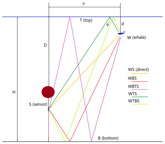
Figure 10.
This diagram shows the parametrization of the problem with a whale at depth d, a sensor at depth D, and an ocean depth of H. θ is the angle between a ray and the vertical. The direct path between the whale and sensor is named WS. Four additional reflected paths are shown on the diagram and named WBS, WBTS, WTS, and WTBS. WS, and the first legs of WBS and WBTS propagate downward, while the first legs of WTS and WTBS propagate upward. Table 2 shows the theoretical travel time for these five rays and two additional rays as a function of v, θ, x, d, D, and H.

Table 2.
Travel time calculation for one direct and seven reflected paths.
The localization of each call is accomplished by a simple grid search. The search finds the location which minimizes the root mean square (RMS) of the difference between the measured and modeled values of the nine parameters extracted from the waveforms. Straight ray propagation and a water velocity of 1480 m/s are assumed. The grid spacing can be adjusted as desired. For examples presented in this work, the latitude and longitude grid spacing is 5 m, and the depth spacing 2.5 m. Specifically, the grid search for the first call is initially performed in a 5 km × 5 km × 50 m volume centered on the surface projection of the S1 hydrophone. For later calls, the search is limited to an area of 1 km × 1 km × 50 m centered on the previous location, since the animal cannot travel far from one call to the next when the call spacing is about 50 s between calls of the same type. This provides a very substantial efficiency gain for the grid search.
A step-by-step summary of the grid search algorithm is provided in the following table (Algorithm 2):
| Algorithm 2 Grid search for optimal location | |
Input:
Processing time: For an interval of 18 min, on a Google backend via Colaboratory, when searching through 20 depths and the grid dimensions and spacing mentioned in steps 1 and 3 below, the processing time is 627 to 631 s. | |
| Step 1 | For the initial detection, assume a starting whale depth, water velocity v = 1480 m/s, and straight-line propagation. For each point of a 1000 × 1000 × 20 grid, with 5 m spacing horizontally and 2.5 m vertically (5 km × 5 km × 50 m), centered on the surface projection of hydrophone S1, compute the RMS of the difference between the observed and estimated DTOA and differences between times of reflected and direct paths:
|
| Step 2 | X [1] is the grid point [p, q, z]opt with the lowest value of RMS[p, q, z] over all p, q and z grid points. |
| Step 3 | For later groups of detections, search a 200 × 200 × 20 grid around the previous location, X[i − 1]. The same 5 m horizontal spacing and 2.5 m vertical spacing (1 km × 1 km × 50 m) are used. A smaller grid is sufficient since the whale is unlikely to move further than 0.5 km within the time between consecutive calls. |
3. Results
3.1. Whale Track on an Eighteen-Minute Interval After 23:03 UTC Using TDOA and Two Reflections
The waveform processing and grid search method were applied to the eighteen-minute time interval starting at 23:02 UTC. This time interval was chosen because it starts after a 4 to 5 min pause in vocalization and is followed by another pause of similar length. Furthermore, it contains two series of B calls interrupted by a short pause of 1-to-2 min. The B calls were chosen to delineate the track because of their better time resolution than the A calls. The first series contains 15 B calls and the second contains 7 B calls. Figure 8 shows the envelopes of all 22 segments with B calls within that interval. The automatic time picks, including the direct arrival and two reflections, are complete for each segment in this interval. Additional picks are visible in some segments but were not interpreted and used in the analysis. The first three times picked on each of the envelopes are interpreted as direct arrival and two of the reflections depicted on Figure 10. It is a matter of interpretation to identify which paths we are observing in terms of delays after direct arrival, and the best fit with the delays are the WBS and the WBTS paths illustrated in Figure 10. Both have a downward first leg, similar to the direct path.
The grid search algorithm was tested with starting whale depths of 50 m and 190 m for the initial call in the series and the results all converge after the second or third call location to depths between 50 m and 100 m. The depth of the ocean is assumed to be the nominal published depth of 1174 m. The results for a starting value of 50 m for the whale depth are shown in Figure 11. Figure 11a–c show the fits of the modeled travel times and delays to the picks made on the envelopes of the waveform segments around each B call. Figure 11d shows the depth estimate for each of the 22 B calls. The depth is relatively constant, oscillating between 50 m and 85 m. Figure 11e shows the track of the whale which lies entirely within the perimeter delimited by the three hydrophones for this time interval. Given that the resulting track lies in an area where the depth is close to the published value of 1174 m using that value as a parameter for this location is justified. The inset in Figure 11e shows the limits of Figure 11f which is a close-up of the track. Every fifth location is highlighted in yellow in Figure 11f, and annotated with the time of the call, in minutes from 18:00 UTC, showing the progression of the animal with time. Note that the two series of calls (the first 15 calls, followed by the next 7 calls) correspond to two separate path segments interrupted by a 1 to 2 min pause during which the animal seems to have accomplished a sharp turn. Figure 11f shows one path segment starting at minute 303 and includes minutes 306 and 310, and continues on its trajectory for another 4 calls for a total of 15 calls. The next segment starts at minute 314 and contains minute 317 and an additional call after that, for a total of seven calls.
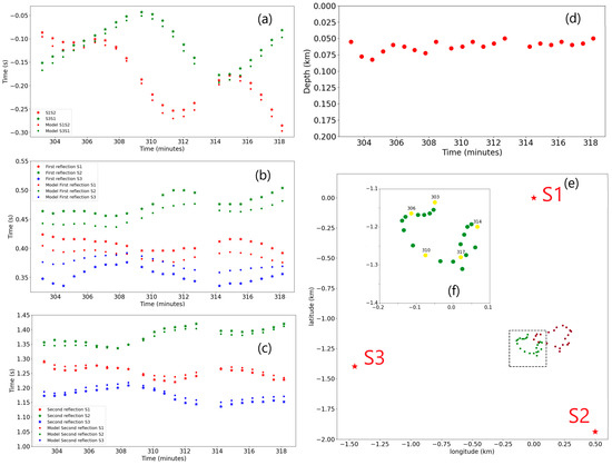
Figure 11.
Results for the 18 min interval after 23:02 UTC. (a) Fit for the d12 and d31 TDOAs. (b) Fit for the time difference between first reflection and direct arrival. (c) Fit for the time difference between second reflection and direct arrival. (d) Optimal depths. (e) A map showing the whale track (in green) with respect to the location of the three hydrophones (red stars). The dark red dots are the track obtained when using only the first reflection delays. (f) The inset showing the details of the track. The yellow dots are labeled with the time of the corresponding call, in minutes.
The fits for the TDOA and the second reflection (Figure 11a,c) are quite good while the residuals for the first reflection are higher than for the other two parameters. Tests were conducted to assess the effect of adding the reflections to constrain the tracking. The results presented in Figure 11 are for a configuration where the TDOA and both reflections are used. The tracks, time parameter fits, and depths were calculated for additional configurations of TDOA only, TDOA plus the first reflection, and TDOA plus the second reflection. It was found that
- The horizontal projection of the track is not altered significantly when using these four configurations. All tracks obtained remain with 25 m of each other.
- The depth estimates shown in Figure 11d vary between 50 m and 85 m, while when TDOA only are used, they become positive, which is unrealistic.
- When only the first reflection is added to the TDOA, the depth varies between 10 m and 70 m.
- When only the second reflection is added to the TDOA, the depth varies between 62 m and 90 m.
Therefore, as would be expected, the addition of at least one reflection to the TDOA stabilizes the depth estimate.
The fit for the first reflection is consistently the worst for the four configurations listed above. When only the first reflection is used, the fit to the reflection time delays becomes very good, however the track departs significantly from the track obtained from the other four configurations. It moves away from the location of hydrophone S3 (see dark red dots on Figure 11e). This may be an indication that the published location we have for S3 may not be accurate and that S3 lies a few tens of meters further west.
The values of depth are compatible with the range of depth of vocalization observed on tagged fin whales in the Southern California Bight [17]. Although the majority of the tagged fin whale dives were recorded at shallow depths of 15–20 m, some dives were as deep as 300 m, presumably when the whale was feeding.
3.2. Whale Track on Multiple Hours Interval with Constant Depth Constraint
The horizontal path is insensitive to the addition of reflections, which seem to control the depth. Two reflections were identified automatically on the majority of calls in the interval between 21:00 UTC and 7:30 UTC, but not on all of them, contrary to the 18 min interval presented in the previous section. To treat all calls in the same manner, we performed a grid search using only the TDOA and a depth constraint of 50 m for the 430 B calls within that long interval. The bathymetry was fixed at 1174 m, the nominal value from Table 1.
The resulting track is shown on Figure 12. Two versions are presented, color-coded by parameter (a1/a2-d2/d1) in Figure 12a, and the other color-coded by parameter (a3/a1-d1/d3), where a1, a2, and a3 are the amplitudes of the direct arrivals, and d1, d2, and d3 the distances to, respectively, hydrophones S1, S2, and S3. Assuming that the amplitudes decay as 1/R, where R is the distance between the source and the receiver, the ratios of amplitudes at two hydrophones should be the inverse of the ratio of distances. A circle of radius 1.5 km centered on point S0, the geographic center of the hydrophone triplet, is shown in black on the maps. The histograms for the values of the residual values (a1/a2-d2/d1) and (a3/a1-d1/d3) are shown below each map. If the decay with distance is indeed as 1/R, the color-coded tracks and the histograms should be close to zero. For (a1/a2-d2/d1), it is generally the case, except for the portion of the track shown on Figure 12a which moves towards hydrophone S1 and back, which shows a strongly positive bias. That portion of the track accounts for the positive tail on the histogram in Figure 12c and corresponds to a time around 03:45 UTC and we will focus on it in a section below with a computation involving a deeper ocean, as is the case under hydrophone S1, and the use of two reflections to better define the track, including the depth. The main lobe of the distribution of (a1/a2-d2/d1), between −0.25 and +0.25 is centered on the zero while the main lobe of (a3/a1-d1/d3) is centered on a slightly negative bias value. This again may indicate that the true location of S3 may be further west than the values we used in this work.
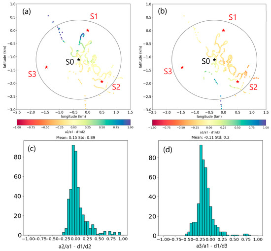
Figure 12.
(a) A map showing the location of 460 B calls defining the whale track between 21:00 UTC and 7:30 UTC. The red stars are hydrophone locations annotated with their name. The black star is the location of S0, the triplet center. The black circle has a radius of 1.5 km centered on S0. The dots mapping the whale track are color-coded with the residual value of the ratio’s differences (a1/a2-d2/d1). (b) The same applies for the residual values (a3/a1-d1/d3). (c) The histogram for (a1/a2-d2/d1). (d) The histogram for (a3/a1-d1/d3).
Once the whale track is obtained with discrete values at the locus of vocalization, distances to each of the three hydrophones can be calculated. Figure S5 in the Supplementary Materials shows the variation in the amplitude of the direct arrival in dB with the log of distance. The best fitting line, in red in Figure S5, corresponds to an amplitude decay of 1 over distance. It is found to be x, where A is the amplitude in dB Re 1 μPa, b is 140.8 ± 1.9 dB Re 1 μPa, x is the distance in km, and m is −21 dB Re 1 μPa. The black lines below and above the best fitting line correspond to ±1.9 dB Re 1 μPa. Note that they would encompass all points if the distance to S3 was underestimated. The SL of the B calls can be estimated by estimating the received level at 600 m, and extending to 1 m. The average received level at 600 m is 145.5 ± 1.9 dB Re 1 μPa, to which 20 log10 600 (55.6) need to be added for the transmission loss (TL) between 600 m and 1 m, assuming inverse of distance decay. Therefore, the SL is 201.1 ± 1.9 dB Re 1 μPa at 1 m. This range of values places the SL higher than the average, 189 dB Re 1 μPa at 1 m for other published estimates for fin whales [33]. This higher level may result from the short range at which the records are made. A possibility is also that directivity plays a role, with a higher received level for hydrophones located below the animal.
In addition to the distance to the hydrophone, the speed and distances between consecutive calls can be estimated. Figure S6a shows the histograms of estimated horizontal swim speed of the whale as measured between two consecutive B calls within 1.5 km from S0, and eliminating the outlier speeds larger than 50 km/h. The mean speed is estimated to be 2.56 ± 1.93 km/h. A histogram of the distance between two B calls is shown in Figure S6b, with the mean distance estimated at 49 m ± 84.75 m.
Figure S7 shows the inter-call distance as a function of time on part of the data. Note the outliers showing the distance between the last call of the previous dive and the first call of the next dive. These explain the secondary peak in the inter-call distance histogram between 100 m and 200 m and the large standard deviation. Since the distance between dives diminishes with time for this time interval, it may indicate a slower motion as the animal reaches the seamount underlying the triplet.
Obtaining the track also allows a visualization of the reflections on the waveforms ordered by distance from the hydrophones. Figure 13a–c shows waveform offset gathers as a function of distance for each of the three hydrophones. The zero on the traces is the arrival time of WS, the direct arrival. Note that multiple water reflections are visible. Also shown on the plot are theoretical arrival times for a water depth of 1174 m and whale depth of 50 m. Shown superimposed on the S1, S2, and S3 hydrophones sections are the WBS and WBTS theoretical arrival times, with small black dots. These are the reflections used in the grid search. The pairs (WS, WTS), (WBS, WTBS), (WBTS, WTBTS), and (WBTBS, WTBTBS) are very close in time, as expected for a whale depth of 50 m. The theoretical arrival times for WBTS and WBTBS, not used in the grid search, are shown as yellow dots. The theoretical arrival times for WTBS, WTBTS, WTBTBS, and WTBTBTS are shown as magenta dots. No theoretical values are plotted for the later reflections, of which one more is visible in all three sections on Figure 13a–c, and four more would be visible up to 7 s after the direct arrival.
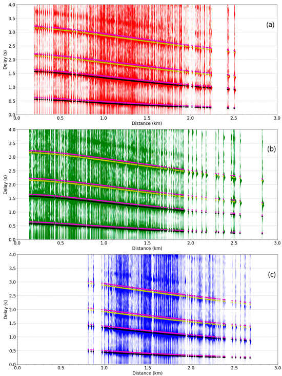
Figure 13.
(a) Section plot for hydrophone S1 showing 4 s waveform envelope segments for B calls, in red. Ramp function is applied (25 * t, t in seconds) to emphasize later arrivals. (b) Same for hydrophone S2, in green. (c) Same for hydrophone S3, in blue. WBS and WBTS are shown as black dots, WBTBS and WBTBTS as yellow dots, and WTBS, WTBTS, WTBTBS, and WTBTBTS as magenta dots.
Note that near zero offset, the separation between the second (WBS) and third reflection (WBTS) is about 1 s. That separation corresponds to the two-way time between the hydrophone and surface for a depth of 740 m if we use a velocity of 1.48 km/s. This is close to the actual depths of the hydrophones. Similarly, the separation between the water multiples, for instance between WS and WBTS is about 1.6 s, corresponding to an ocean depth of 1184 m, close to the nominal depth of 1174 m. This means the theoretical calculations with the formulas listed in Table 2 are compatible with the observations.
3.3. Whale Track on an Eighteen-Minute Interval After 03:49 UTC Using TDOA and Two Reflections
It was pointed out in the previous section that the portion of the track obtained in 3.2 that is close to hydrophone S1 presented large values of the residuals (a1/a2-d2/d1). This corresponds to a time around 03:49 UTC, and for an eighteen-minute interval after that time, a more complete analysis was conducted, using the TDOA and both reflections time delays to obtain a track of the whale within that time period with a better depth constraint. Three of the reflection delay values (out of forty-four) were excluded from the grid search analysis since they were clear outliers. All values of the TDOA and all of the other reflection delay values were used. A value of 1250 m, close to 1280 m at hydrophone S1, was used for bathymetry since the ocean is deeper under hydrophone S1 than the other two hydrophones, according to the values read on Google Earth [32].
The results are presented in Figure 14. The projection of the track on the horizontal plane is very close to the results obtained when the depth was constrained at 50 m, as presented in Section 3.2. Since the reflection times were used, a depth estimate was obtained, and it was found that it varies between 380 m and 440 m, 250 to 350 m deeper than the depth obtained for the other eighteen-minute interval starting at 23:02 UTC. The residual values (a1/a2-d2/d1) were recomputed for the new locations of the call and the results shown in Figure 14e. It is clear that they are much reduced from the values obtained when the depth is constrained at 50 m, and closer to what is expected for amplitude ratios when the depth of the whale is indeed deeper than 50 m.
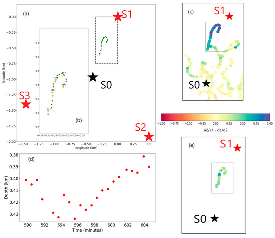
Figure 14.
(a) The map of the track (green dots) for the eighteen-minute time interval after 03:49 UTC is similar to Figure 11, with the rectangular limits of the inset presented in (b). (b) This part also highlights in yellow the locations annotated in minutes from 18:00 UTC. (c) A reproduction of a portion of the map of Figure 12b. (d) The depth corresponding to the locations in (a,b). (e) The color-coded values of (a1/a2-d2/d1) for the locations and depths shown in (a,b,d).
This analysis shows the interest of using amplitudes to confirm results obtained based purely on travel times. It also shows the sensitivity of the whale depth results to the exact ocean depth used in the analysis.
4. Discussion
Waveforms originating from vocalizing fin whales recorded on the IMS hydroacoustic station HA11 have been presented and analyzed to estimate optimal locations of the whales from the TDOAs and reflection delay times at the three hydrophones. The waveforms recorded for whale calls on each hydrophone are rendered complex by the presence of multiple ocean bottom and surface reflections this close to the triplet of hydrophones. This leads to issues with methods based on cross-correlating segments of waveforms across hydrophone, such as the progressive multi-channel cross-correlation (PMCC) method [34]. Some reflections are as energetic as the first, direct arrival, causing confusion as to which peak in the cross-correlation functions are to be used. To counter this issue, a method was presented that avoids the ambiguity of cross-correlation between traces. The method relies on first delimiting segments around the large amplitudes direct arrivals by applying a power detector. The next step is to extract the source wavelets from the two different types of calls observed on the time interval and cross-correlate these with the time segments. This estimates the bandlimited impulse with time resolution proportional to one over the bandwidth and improves signal-to-noise ratios. The outcome of this cross-correlation is a time series with maxima at the times of the distinct direct and reflected arrivals. The method presents the advantage of separating arrivals, especially for the B calls whose source frequency bandwidth is wider than the A calls. The separation between arrivals also allows a measurement of the amplitudes of individual arrivals.
In this work, we have hypothesized a constant velocity model. We feel that this is justified since we are close to hydrophones and mostly vertical propagation is involved. The error involved in choosing a velocity model to do the analysis, either constant or depth-varying, is likely to be more important than the error involved when a constant velocity is used instead of a depth-varying model.
The results presented in this paper regarding the depth of the vocalizations rely on the accuracy of the published depths of the hydrophones and the bathymetry under the triplet. It is likely that there are in fact differences of possibly up to a few tens of meters between the depths of the three hydrophones, as the mooring cable lengths were pre-established during deployment, but the exact water depth at which the hydrophones were dropped is likely to have deviated from the depth of the target locations, even though a very precise bathymetry was acquired before the deployment. The deployment of the hydrophones is a complex operation with a large surface vessel trying to maintain position while a cable several kilometers long is laid at the bottom of the ocean. Analysis of the amplitudes of the signals exploited in this work points to a possible need for correcting the S3 location to a point further from hydrophones S1 and S2. An inversion problem using both amplitudes and delay residuals to estimate potential corrections to the hydrophone locations may be possible if a very large number of calls are collected. It would be beneficial to search for additional similar sequences, providing better coverage especially close to the S3 hydrophone.
The first two reflections clearly identified in the first few seconds of data after the first arrivals correspond, respectively, to the paths named WBS and WBTS in Figure 10 and Table 2, namely the first bottom reflection and the reflection from the surface after a bottom bounce. It is not clear why the other reflections also expected, WTS and WTBS, are not identified in the data. One possibility is that the source radiates very little acoustic energy towards the top and that most of it is directed towards the bottom. This explanation is compatible with the finding that the estimated SL is higher than the average of other publications, as compiled in [33]. Another possibility is that the arrival times of WTS and WTBS are too close to the other reflections to be separated. This is the case when the depth of the whale is shallow. Figure 13a–c shows how close these arrivals are, for a whale depth of 50 m.
In the results presented in this paper, the bathymetry was fixed for each grid search. If a sufficient number of accurate picks from multiple reflections are included, it should be possible to make the ocean depth a variable and derive the bathymetry from the picked parameters in addition to the whale location and depth. This is the objective of a future project to build on the results of this work.
5. Conclusions
The sequence of calls studied in this work has a long duration and the tracks followed by the whale allow for good coverage of the area directly above the triplets. It was shown that using the amplitude ratios of the signal at two different hydrophones when the source is in the near field, less than 1.5 km horizontally from the center of the triplet, can be of interest. The amplitude ratios between hydrophones S1 and S2 confirm that the amplitudes follow the expected decay rule of being inversely proportional to the distance between source and receiver. This is, however, not the case for the amplitude ratios between hydrophones S1 and S3. Several hypotheses may explain this, including that the relative location of hydrophone S3 with respect to hydrophones S1 and S2 needs correction. A non-isotropic radiation pattern, with a maximum directed downward would also explain the apparent absence of observation of the surface reflections in this data set. The reflection paths with a first leg directed downward dominates the recordings. Further collection of similar data with increased coverage may resolve which hypothesis explains the data best.
The estimated average swimming speed of the whale between B calls is 2.56 ± 1.93 km/h. This is obtained when the cetacean is located less than 1.5 km from the center of the triplet, where locations and therefore distances swum are more accurately determined. The swimming speed estimate is compatible with what is known about the maximum speed of 37 km/h (20 knots) for these cetaceans [2]. The horizontal inter-call distance is 49 m ± 84.75 m. The standard deviation is large on this estimate and is explained by outliers when the whale is likely to be between two dives. The larger values correspond to the larger distances between the last call of a previous series, presumably corresponding to a previous dive, and the first call of the next series, presumably corresponding to the next dive.
Given the very close relationship between the locations and relative amplitudes of A and B calls, it is expected that either the source of the calls is a single animal, at least in contiguous periods of time, or if they are from two distinct animals, their relationship must be quite symbiotic. A different conclusion was reached by the authors of [20], using very similar data from February 2019, also from HA11S. They concluded that A and B calls originated from two different animals. Our analysis was repeated on one of the data sets they used, and we concluded that for high SNR calls, we cannot distinguish the tracks computed from the B calls from the tracks from the A calls. One of the A calls they used to reach their conclusion is below the STA/LTA detection we have used, and we would need to apply a different algorithm to detect and time it automatically. These results on the February 2020 data set are presented in the Supplementary Materials.
According to [35], both triplets at HA11 were deployed around a seamount. It may not be a coincidence but rather directed by foraging around that seamount that the whale appears to head towards it and spends a lot of time around it.
As a general conclusion, amplitude may be a source of information additional to the travel times provided that sensor locations are estimated within a few meters and that more is known about the radiation pattern of the acoustic sources. It allowed us to detect that a portion of the track where the amplitude ratios of hydrophone S1 over hydrophone S2 did not match the inverse distance ratios. The track was initially estimated by using a constant depth and the TDOAs only. The ratios became more in line with expectations when the reflection delays were used to better estimate the depth in that portion of the track.
Supplementary Materials
The following supporting information can be downloaded at: https://www.mdpi.com/article/10.3390/jmse13061138/s1. Figure S1: 42 A and 45 B picks on one of the time segments used in reference [20] to illustrate that one A call is located far from track computed from B calls. The time segment starts at 02:00 UTC on 13 February 2020. The data is processed using our method, but with lower STA/LTA threshold for hydrophones S2 and S3 (STA/LTA lowered to [5,4] from [6,5]). The A call illustrated in [20] was below even this threshold. Similarly to our Figure 9, the solid lines are spline fits to B calls for hydrophones S1 (red), S2 (green) and S3 (blue). The picks at these hydrophones are dots with the same colors. The cyan, magenta, yellow dots are the A calls respectively from S1, S2, S3. Because A calls tend to be less consistent (see Figure S3), we have used an outlier quality control before using them further in our analysis. The top panel shows the outliers, the bottom panel has them removed by our outlier procedure; Figure S2: STA/LTA picks for the same data as presented in Figure 2 of reference [20]. The third A call in this time interval is picked only on the S1 hydrophone (left panel), even when lowering the threshold of the STA/LTA procedure to [4,3] from [6,5]. Each panel is like our manuscript Figure 3 with the waveform on top and the STA/LTA trace at the bottom; Figure S3: This figure shows the envelopes of cross-correlated segments for A calls on the left and B calls on the right for the first 9 A calls and the first 9 B calls after 00:50:00. Picks on six of the A calls outlined by the red arrows are not correct since the automatic picking failed to recognize the first arrival showing only as a bump on the first peak. The picking is correct for the B calls. The thin red lines show the alignment on direct arrivals; Figure S4: This figure illustrates the process of source wavelet extraction. The left panel shows the traces aligned on the STA/LTA picks. The right panel shows the alignment after trace to trace cross-correlation. Note the coherence of superimposed traces in blue on the right panel and the larger amplitude of the stack on the right compared to the left panel, as expected; Figure S5: Amplitudes of 460 B calls versus distance, on a dB scale against the log of the distance. The best fitting line corresponding to a negative one slope (amplitude decay as 1 over distance) is shown in red. The two black lines are parallel to the red line with a difference of ± the RMS (1.9) to the fit to the red line. Red, green, and blue correspond respectively to hydrophones S1, S2, and S3; Figure S6: (a) Histogram of the whale’s horizontal speed measured between consecutive B calls. The mean value is 2.56 ± 1.93 km/h. (b) Histogram of the distance between two B calls. The mean value is 49 m ± 84.75 m; Figure S7: Inter-call distance as a function of time in minutes after 18:00 UTC. Interruptions in time are interpreted as surfacing intervals between dives. Note the outliers at the beginning of each interval likely showing surface swims up to 200 m between dives.
Author Contributions
Conceptualization, R.L.B. and P.N.; methodology, R.L.B.; software, R.L.B.; formal analysis, R.L.B. and P.B.; data curation, R.L.B.; writing—original draft preparation, R.L.B.; writing—review and editing, P.N. and P.B. All authors have read and agreed to the published version of the manuscript.
Funding
This research received no external funding.
Data Availability Statement
The data from IMS hydroacoustic station HA11 is openly available at the IRIS data center [21]. The data from HA01 can be obtained via the vDEC [36] mechanism of the CTBTO.
Conflicts of Interest
The authors declare no conflicts of interest.
References
- CTBTO. 2025. Available online: www.ctbto.org (accessed on 3 March 2025).
- International Whaling Commission. Available online: https://iwc.int/about-whales (accessed on 7 July 2024).
- Watkins, W.A. Activities and Underwater Sounds of Fin Whales. Sci. Rep. Whales Res. Inst. 1981, 33, 83–117. [Google Scholar]
- CTBTO. IMS Map. Available online: https://www.ctbto.org/sites/default/files/2024-10/IMS_Map_FRONT_BACK_AUGUST_2021_web2.pdf (accessed on 12 November 2024).
- Munk, W.H. Sound channel in an exponentially stratified ocean with applications to SOFAR. J. Acoust. Soc. Am. 1974, 55, 220–226. [Google Scholar] [CrossRef]
- Thode, A. Tracking sperm whale (Physeter macrocephalus) dive profiles using a towed passive acoustic array. J. Acoust. Soc. Am. 2004, 116, 245–253. [Google Scholar] [CrossRef] [PubMed]
- Thode, A.M.; Kim, K.H.; Blackwell, S.B.; Greene, C.R.; Nations, C.S.; McDonald, T.L.; Macrander, A.M. Automated detection and localization of bowhead whale sounds in the presence of seismic airgun surveys. J. Acoust. Soc. Am. 2012, 131, 3726–3747. [Google Scholar] [CrossRef] [PubMed]
- Miksis-Olds, J.L.; Harris, D.V.; Heaney, K.D. Comparison of estimated 20-Hz pulse fin whale source levels from the tropical Pacific and Eastern North Atlantic Oceans to other recorded populations. J. Acoust. Soc. Am. 2019, 146, 2373–2384. [Google Scholar] [CrossRef] [PubMed]
- Harris, D.V.; Miksis-Olds, J.L.; Vernon, J.A.; Thomas, L. Fin whale density and distribution estimation using acoustic bearings derived from sparse arrays. J. Acoust. Soc. Am. 2018, 143, 2980–2993. [Google Scholar] [CrossRef] [PubMed]
- Balcazar, N.E.; Tripovich, J.S.; Klinck, H.; Nieukirk, S.L.; Mellinger, D.K.; Dziak, R.P.; Rogers, T.L. Calls reveal population structure of blue whales across the southeast Indian Ocean and the southwest Pacific Ocean. J. Mammal. 2015, 96, 1184–1193. [Google Scholar] [CrossRef] [PubMed]
- Gavrilov, A.N.; McCauley, R.D.; Salgado-Kent, C.; Tripovich, J.; Burton, C. Vocal characteristics of pygmy blue whales and their change over time. J. Acoust. Soc. Am. 2011, 130, 3651–3660. [Google Scholar] [CrossRef] [PubMed]
- Gavrilov, A.N.; McCauley, R.D. Acoustic detection and long-term monitoring of pygmy blue whales over the continental slope in southwest Australia. J. Acoust. Soc. Am. 2013, 134, 2505–2513. [Google Scholar] [CrossRef] [PubMed]
- Le Bras, R.J.; Kuzma, H.; Sucic, V.; Bokelmann, G. Observations and Bayesian location methodology of transient acoustic signals (likely blue whales) in the Indian Ocean, using a hydrophone triplet. J. Acoust. Soc. Am. 2016, 139, 2656–2667. [Google Scholar] [CrossRef] [PubMed]
- Le Bras, R.J.; Nielsen, P. Range estimates of whale signals recorded by triplets of hydrophones. In Proceedings of the AGU Fall Meeting, New Orleans, LA, USA, 11–15 December 2017. [Google Scholar]
- Sirovic, A.; Hildebrand, J.A.; Wiggins, S. Blue and fin whale call source levels and propagation range in the Southern Ocean. J. Acoust. Soc. Am. 2007, 122, 1208–1215. [Google Scholar] [CrossRef] [PubMed]
- Kuna, V.M.; Nábělek, J.L. Seismic crustal imaging using fin whale songs. Science 2021, 371, 731–735. [Google Scholar] [CrossRef] [PubMed]
- Stimpert, A.; DeRuiter, S.; Falcone, E.; Joseph, J.; Douglas, A.B.; Moretti, D.J.; Friedlaender, A.S.; Calambokidis, J.; Gailey, G.; Tyack, P.L.; et al. Sound production and associated behavior of tagged fin whales (Balaenoptera physalus) in the Southern California Bight. Anim. Biotelemetry 2015, 3, 23. [Google Scholar] [CrossRef]
- Pereira, A.; Harris, D.; Tyack, P.; Matias, L. On the use of the Lloyd’s Mirror effect to infer the depth of vo-calizing fin whales. J. Acoust. Soc. Am. 2020, 148, 3086–3101. [Google Scholar] [CrossRef] [PubMed]
- Lloyd, H. On a New Case of Interference of the Rays of Light. In The Transactions of the Royal Irish Academy; Royal Irish Academy: Dublin, Ireland, 1831; pp. 171–177. [Google Scholar]
- Zhu, J.; Wen, L. Hydroacoustic study of fin whales around the Southern Wake Island: Type, vocal behavior, and temporal evolution from 2010 to 2022. J. Acoust. Soc. Am. 2024, 155, 3037–3050. [Google Scholar] [CrossRef] [PubMed]
- Various Institutions. International Miscellaneous Stations. International Federation of Digital Seismograph Networks. 1965. Available online: https://www.fdsn.org/networks/detail/IM/ (accessed on 3 March 2025).
- Lawrence, M.; Haralabus, G.; Zampolli, M.; Metz, D. The Comprehensive Nuclear-Test-Ban Treaty Hydroacoustic Network; Lawrence, M., Haralabus, G., Zampolli, M., Metz, D., Eds.; Comprehensive Nuclear-Test-Ban Treaty Organization: Vienna, Austria, 2024. [Google Scholar]
- Krischer, L.; Megies, T.; Barsch, R.; Beyreuther, M.; Lecocq, T.; Caudron, C.; Wassermann, J. ObsPy: A bridge for seismology into the scientific Python ecosystem. Comput. Sci. Discov. 2015, 8, 17. [Google Scholar] [CrossRef]
- Google. Google Colaboratory. 2024. Available online: https://colab.research.google.com/ (accessed on 16 March 2025).
- Thomas, K.; Benjain, R.-K.; Fernando, P.; Brian, G.; Matthias, B.; Jonathan, F.; Kyle, K.; Jessica, H.; Jason, G.; Sylvain, C.; et al. Jupyter Notebooks—A publishing format for reproducible computational workflows. In Positioning and Power in Academic Publishing: Players, Agents and Agendas; Loizides, F., Schmidt, B., Eds.; IOS Press: Amsterdam, The Netherlands, 2016; pp. 87–90. [Google Scholar]
- Watkins, W.A.; Tyack, P.; Moore, K.E.; Bird, J.E. The 20-Hz signals of finback whales (Balaenoptera physalus). J. Acoust. Soc. Am. 1987, 82, 1901–1912. [Google Scholar] [CrossRef] [PubMed]
- Trnkoczy, A. Understanding and Parameter Setting of STA/LTA Trigger Algorithm. 2011. Available online: https://gfzpublic.gfz-potsdam.de/pubman/item/item_43337 (accessed on 3 March 2025).
- Allen, R. Automatic earthquake recognition and timing from single traces. Bull. seism. Soc. Am. 1978, 68, 1521–1532. [Google Scholar] [CrossRef]
- Le Bras, R.J.; Mialle, P.; Kushida, N.; Bittner, P.; Nielsen, P. Developments in Hydroacoustic Processing for Nuclear Test Explosion Monitoring; Kalinowski, M.B., Haralabus, G., Labak, P., Mialle, P., Sarid, E., Zampolli, M., Eds.; Comprehensive Nuclear-Test-Ban Treaty Organization: Vienna, Austria, 2024. [Google Scholar]
- von Hann, J. Handbook of Climatology; Nabu Press: Charleston, SC, USA, 1903; p. 199. [Google Scholar]
- Yilmaz, O. Seismic data analysis. In Processing, Inversion, and Interpretation of Seismic Data; Society of Exploration Geophysicists: Tulsa, OK, USA, 2001. [Google Scholar]
- Google. Google Earth. Available online: https://earth.google.com/intl/earth/versions/ (accessed on 16 March 2025).
- Bouffaut, L.; Goestchel, Q.; Rørstadbotne, R.; Sladen, A.; Hartog, A.; Klinck, H. Estimating sound pressure levels from Distributed Acoustic Sensing data using 20-Hz fin whale calls. JASA Express Lett. 2025, 5, 040802. [Google Scholar] [CrossRef] [PubMed]
- Cansi, Y.; Le Pichon, A. Infrasound Event Detection Using the Progressive Multi-Channel Correlation Algorithm. In Handbook of Signal Processing in Acoustics; Springer: New York, NY, USA, 2009; pp. 1425–1435. [Google Scholar]
- Constructing Hydroacoustic Station HA11 Wake Island. Available online: https://www.ctbto.org/news-and-events/news/braving-storms-constructing-hydroacoustic-station-ha11-wake-island (accessed on 22 July 2024).
- VDEC. Available online: https://www.ctbto.org/resources/for-researchers-experts/vdec (accessed on 10 July 2024).
Disclaimer/Publisher’s Note: The statements, opinions and data contained in all publications are solely those of the individual author(s) and contributor(s) and not of MDPI and/or the editor(s). MDPI and/or the editor(s) disclaim responsibility for any injury to people or property resulting from any ideas, methods, instructions or products referred to in the content. |
© 2025 by the authors. Licensee MDPI, Basel, Switzerland. This article is an open access article distributed under the terms and conditions of the Creative Commons Attribution (CC BY) license (https://creativecommons.org/licenses/by/4.0/).