1. Introduction
When the ship is used for wind power generation operation and maintenance, offshore lifting, and other operations, due to wind, waves, currents, and other reasons, the ship exhibits complex movements in six degrees of freedom (6-DOF) [
1,
2]. This will affect the safety of the operating equipment and the accuracy of the measurement results of the measuring instruments, thus greatly reducing the ship operation time. In order to reduce the impact of waves and other environmental factors on operations, wave compensation equipment uses some control algorithms to compensate for the speed and displacement caused by waves on operating ships, hoisted objects, and transfer personnel [
3]. Therefore, various types of wave compensation equipment are generally assembled in the transfer of goods and personnel, deep-sea petroleum and gas resource development, and other operations, which greatly improves the safety of offshore work and extends the work cycle [
4].
Since the application of wave compensation systems, various forms of wave compensation systems have appeared. According to the working principle, it can usually be classified as the following three categories: passive, active, and composite systems [
5]. From the classification of the compensation degrees of freedom, it can mainly be classified as follows: heave direction compensation, heave–roll–pitch direction compensation, and 6-DOF compensation systems [
6]. With the development and needs of ocean engineering, offshore engineering equipment with a high precision and multi-degree-of-freedom compensation has attracted more attention. The Stewart platform with 6-DOF is considered an ideal choice [
6]. The Stewart platform was designed by British Gough as early as 1954. It mainly consists of top and base platforms and six actuators connecting the two platforms [
7]. In the early days, the platform was fixed to a stationary base platform for use. By controlling the extension or contraction of the six actuators, the upper platform can move in 6-DOF directions. It is extensively used in the medical industry, automobile manufacturing, the aerospace industry, and other industries. At the World Wind Energy Conference in Berlin in 2002, two Ph.D. students at the University of Delft, Jan van der Tempel and David-Pieter Molenaar, first put forward the idea of installing a Stewart platform on the deck of a ship to compensate for all freedom, and the concept of movement, later named “Ampelmann” [
8]. The difference from the land-based Stewart platform is that the lower platform is mounted on the deck and acts as a wave compensation platform, moving with the ship during operation. Later, David Cerda Salzmann [
8] proved the feasibility of the Stewart platform as a wave compensation platform. It was combined with inertial sensors and controlled the extension and contraction of six actuators to ensure the upper platform stationary with the fixed earth coordinate system. However, the shipborne Stewart platform disturbances suffer more complicated interference than the Stewart platform with a fixed bottom. For example, the base platform will have random motion with the ship due to random waves. Moreover, the nonlinear properties of the multi-degree-of-freedom mechanism will also bring great challenges to the design of the control algorithm [
6].
The value of the relevant parameters in the control algorithm will have a decisive effect on the performance of the control system. In addition, different control algorithms have a great influence on the motion compensation accuracy of platform [
9]. For the past few years, a lot of studies have been conducted on the Stewart platform control algorithm design, such as the PID control algorithm, adaptive control [
10], the sliding mode control algorithm [
11], and robust control [
12].
Şumnu et al. [
13] conducted the kinematic and dynamics analysis of the platform with linear motors, and simulated the PID control system in MATLAB where the parameters were fixed. Wu et al. [
14] and Chen et al. [
6] both adopted the active disturbance rejection control (ADRC) control strategy to control the Stewart platform, and verified that the algorithm has a good tracking performance through numerical simulation. The algorithm can improve the wave compensation accuracy of the equipment. Liu et al. [
10] used radial basis function neural networks (RBFNNs) to construct an active adaptive heave compensation control system. The method is verified to have better effects than the traditional PID method through simulation and experiment. Cai et al. [
11,
12,
15] aimed at the problem of uncertainty in the load and hydraulic system, and used the sliding mode control strategy added speed feedforward compensation and adaptive robust control, respectively, for the Stewart platform, and the effects of the combination method was verified through a simulation comparison. Zhang et al. [
16] designed a back-stepping control method on shipboard wave heave compensation equipment to counteract the motion of a ship caused by waves, and applied an optimization algorithm to optimize the relevant parameters. The simulation shows that, in simulated regular waves and irregular waves, the new method has achieved good results. Lv et al. [
17] designed a PD control algorithm for a three-degrees-of-freedom platform. Through simulation and experiment, the control accuracy of this control algorithm was improved compared with the PD control algorithm. Yin et al. [
18] designed a robust control algorithm to ensure that the top part of Stewart platform remains stationary in the existence of external perturbations. Chen et al. [
19] introduced the modal space control strategy into Stewart’s control strategy, fully considered the inertia characteristics, and designed a PD control algorithm and a sliding mode control algorithm. Finally, the superiority of the new model and control algorithm for compensation accuracy and anti-interference capability were verified through simulation. Valente and Perondi [
20] used a feedback control method on the wave compensation equipment, and achieved a good vibration reduction effect. Vu et al. [
21] added a fuzzy enhancement strategy to the SMC method, which reduced the vibration of the platform very well.
From the above research on control, it can be seen that most methods require accurate object models, and the derivation of the mathematical models may be complex. If there are an inaccurate model and dynamic properties that have been ignored, the performance of the control algorithm will deteriorate. These control algorithms are difficult to fully adapt to shipboard Stewart platforms operating in variable sea conditions [
21]. Because it is not sensitive to the exact model of the control member, traditional PID control is easier to use. Nevertheless, the initial control parameters are invariable. For wave compensation systems with variable disturbance, nonlinearity, and a time delay, it is not easy to obtain good real-time tracking results [
6]. In recent years, artificial intelligence algorithms such as neural networks have been extensively used in many fields [
22,
23]. Among them, the BP neural network model is extensively used at present [
24]. As a multi-layer backpropagation neural network, it has adaptive learning capabilities, and can theoretically approximate nonlinear functions with arbitrary accuracy.
To solve these problems, a novel control scheme is proposed in this paper that integrates a BP neural network with a PID control algorithm to optimize the performance of an electric cylinder-driven Stewart wave compensation platform. This control scheme utilizes a BP neural network to adjust the PID parameters online. The PID control algorithm serves as the main control algorithm, while the BP neural network identifies the unknown parameters of the control system and adjusts the PID settings to mitigate external disturbances. Additionally, the gradient descent with a momentum term is used in the neural network, which reduces the sensitivity to local details, allowing it to quickly find the global minimum and increase the convergence speed.
The rest of this article consists of the following sections: In the
Section 2, a system model of the shipborne Stewart platform is built. Then, a PID control algorithm based on BP neural network is designed in
Section 3.
Section 4 gives the simulation results of the traditional method and the proposed method in this paper, and the performance comparison is carried out. In the end,
Section 5, the conclusion is provided in this work.
2. System Modeling
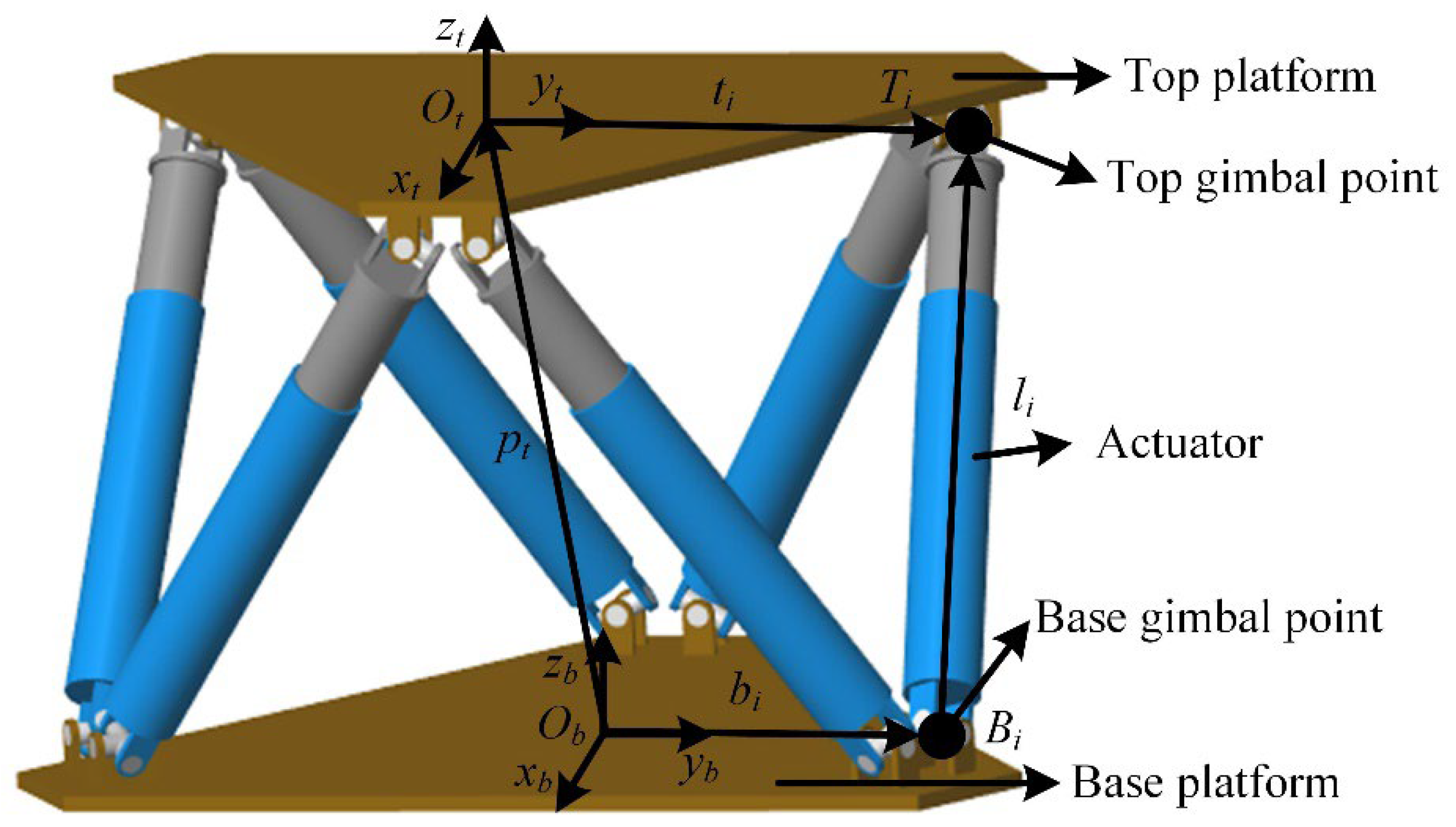
As shown in
Figure 1, the Stewart platform used in this article include, primarily, a base platform, a top platform, and six actuators. Each actuator is an electric cylinder, which mainly consists of a permanent magnet synchronous motor (PMSM). The upper end and bottom end of the electric cylinder are fixed to the upper and lower platform, respectively, through the universal joint.
2.1. Kinematic Analysis
The shipborne Stewart wave compensation platform moves with the motion of the vessel, which is measured by an Inertial Measurement Unit (IMU). When the platform is operational, the control algorithm adjusts the lengths of the six actuators to modify the posture of the top platform, ensuring it remains stationary and counteracting any unwanted motion.
In
Figure 1, the following coordinate systems are built.
Ob − xbybzb and
Ot − xtytzt represent the base platform and the top platform coordinate system, respectively, which are located at the centers of the base and top platforms, respectively. The position vector and the rotation angle vector of the base platform and the top platform relative to the world coordinate system are expressed as follows, respectively:
and
. Among them, Euler angles
,
, and
represent the angles in the RPY direction. The mobile coordinate system rotates around the fixed coordinate system in the order of
x-y-z. The corresponding rotation matrix is given in Equation (1).
According to the position vector and the rotation angle vector information of the base and top platforms, the inverse kinematics method is used to solve the lengths of the six actuators. According to the vector relationship, the length of each actuator is written as Equation (2).
In the formula, is the length of the six actuators, is the unit vector from Bi to Ti, is the displacement of the upper platform coordinate origin Ot relative to the lower platform coordinate origin Ob, represents the rotation transformation matrix from the top platform to the base platform, is the position vector of the universal node Bi in the base platform, and is the position vector of the universal node Ti in the top platform.
The speed loop formula can be expressed in Equation (3).
where
is the angular velocity of the center of the top platform in the base platform, and
is the angular velocity of the actuator in the base platform.
is the linear velocity of the origin of the top platform relative to the base platform.
For six actuators, their length and the pose matrix form of the top platform are written as Equation (4).
In the formula,
,
, and the Jacobi matrix
J as a 6×6 matrix is expressed in Equation (5).
2.2. Dynamics Model
Dynamic modeling is very important for platform control, especially for parallel robots where precise positioning and ideal dynamic characteristics are the main requirements. The general form of the parallel robot dynamics equation [
25] is given in Equation (6).
Here,
X is the generalized coordinate vector,
M is the inertia matrix of the system,
C is the Coriolis force and centrifugal force matrix,
G is the gravity vector, and
F is the generalized force.
The components of each part in the above formula are given in Equation (7) [
25].
Here,
Mt and
Mli are the mass matrices of the top platform and the six actuators, respectively;
Ct and
Cli are force matrices of the top platform and the six actuators, respectively;
Gt and
Gli are the gravity vectors of the top platform and the six actuators, respectively; and
Ft and
Fli are the external interference force vectors of the upper platform and the six actuators, respectively.
When using the Newton–Euler method to establish the actuator dynamics equation, a local generalized coordinate xi is considered, which is the position of Ti. In order to map the local generalized coordinate xi to the generalized coordinate X, a Jacobian matrix Ji is defined.
The correlation matrix of the top platform and the six actuators is given in Equations (8)–(13).
where
and
denote the position vectors of the center of mass of upper and lower pairs of each actuator, respectively, and
and
denote the mass of upper and lower pairs of each actuator, respectively.
Intermediate variables are given in Equations (14)–(17).
The top platform correlation matrix is given in Equation (18).
2.3. The Actuator Model
The electric cylinder is a servo system that transforms the rotational angle of the PMSM into displacement motion at the end of the electric cylinder through a ball screw.
According to the mechanical characteristics, there is a proportional connection between the electric cylinder displacement and the motor rotation angle. In order to simplify the analysis model, factors such as friction and deformation in the movement of the electric cylinder that affect the transmission efficiency are not considered. Therefore, the relationship equation between the displacement of the electric cylinder and the rotation angle of the PMSM can be written as Equation (19).
In the formula, l is the linear displacement of actuators; Bp is the screw lead; is the rotation angle of the motor; and i is the reduction ratio.
In the same way, the relationship between the output force of actuators and the output torque of the PMSM can be written as Equation (20).
where
F is the output force of the electric cylinder; and
T is the output torque of the PMSM.
In general, the secondary factors in the PMSM are ignored [
26]. Through mathematical analysis and a derivation of the model, the relevant equations of the surface PMSM can be obtained.
Stator voltage balance equations are given in Equation (21).
Here,
ud and
uq are the stator voltage.
id and
iq are the stator current.
R is the stator resistance.
and
are the stator flux linkage.
Ld and
Lq are the inductance.
is the flux linkage.
pn is the number of rotor pole pairs.
is mechanical angular speed of the motor.
The electromagnetic torque equation is given in Equation (22).
The torque balance equation on the motor shaft is given in Equation (23).
In the formula, J is the moment of inertia. B is the damping coefficient. TL is the load torque.
id = 0 control is the most commonly used control method for PMSM. The advantage is that it can achieve current decoupling, and the torque is qualitatively good. The motor can obtain a higher control performance, and it is easy to implement. The electromagnetic torque equation is written as Equation (24).
At the same time, we define , and .
In summary, the model of the PMSM can be simplified as Equation (25).
From the above formula, the simplified PMSM model can be obtained through Laplace transform. The model is shown in the
Figure 2.
3. Control Strategy
When controlling the posture of the Stewart platform, the control algorithm uses position loop control, velocity loop control, and current loop control to enable the electric cylinder to generate the force or torque required to move the top platform relative to the bottom platform along a given trajectory. There are many control algorithm architectures, including task-based control algorithms and joint-based control algorithms. In task-based control algorithms, in many practical situations, it is difficult to measure the position and attitude in space. Forward kinematics is usually used to calculate the pose of the top platform. However, the forward kinematics of the Stewart platform is very complex because it requires solving complex equations. Especially, when solving in real time, it is even more difficult [
6]. The inverse kinematics solution of the Stewart platform is simpler, so inverse kinematics is mostly used to design the control algorithm of parallel robots in the joint-space-based algorithm. Under the control algorithm of this architecture, inverse kinematics is used to calculate the expected displacements of the six actuators based on the desired posture of the top platform, and then the force or torque required by the actuators is calculated.
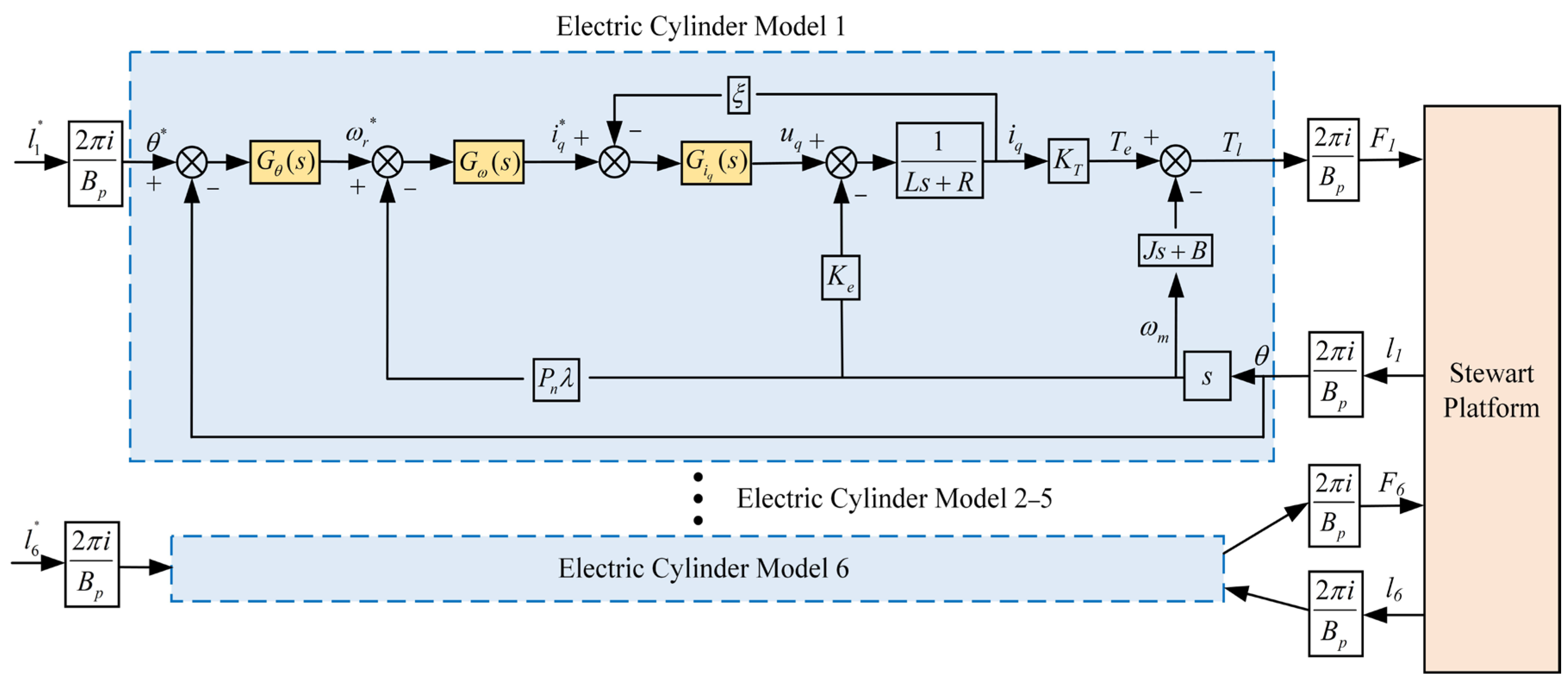
The control of the motion of the Stewart platform is mainly to control the PMSM in the electric cylinder. Usually, the PMSM adopts a three-loop control method, which are the current, speed, and position loop. To guarantee the precise output of the motor shaft, the control strategy often adopts the position control mode of the motor. The position loop usually uses PID control. This control strategy first performs the kinematics inverse solution based on the perturbation posture of the base platform to gain the elongation of the six electric cylinders. The elongation is transferred to the electric cylinders, and then the position of the electric cylinders is determined through three instances of closed-loop control of the motor. Six electric cylinders work together to synthesize the actual posture of the platform. According to the electric cylinder model and Stewart platform model, the overall block scheme can be established as shown in the
Figure 3. The following notations are used in the
Figure 3.
,
, and
represent the transfer functions of the position control algorithm, speed control algorithm, and current control algorithm, respectively. The superscript “*” of the parameter denotes the expected input value of the controller. The subscript of
l and
F represent the actuator number.
and
denote the current loop bandwidth and speed loop bandwidth, respectively. In this paper, the position of the actuator at the middle of the stroke is set as the origin of the position setpoint.
As a traditional control method, PID control is relatively simple and has been widely used in engineering systems [
5]. However, the anti-interference performance of PID control is poor, and the adjustment accuracy under complex models cannot meet the requirements. For the electric cylinder installed on the Stewart compensation platform, due to factors such as the platform time variability, large inertia, and nonlinearity, using the PID control strategy to control the PMSM position loop can no longer ensure the high-quality motion tracking target. Hence, an excellent control method is designed to improve the control effect.
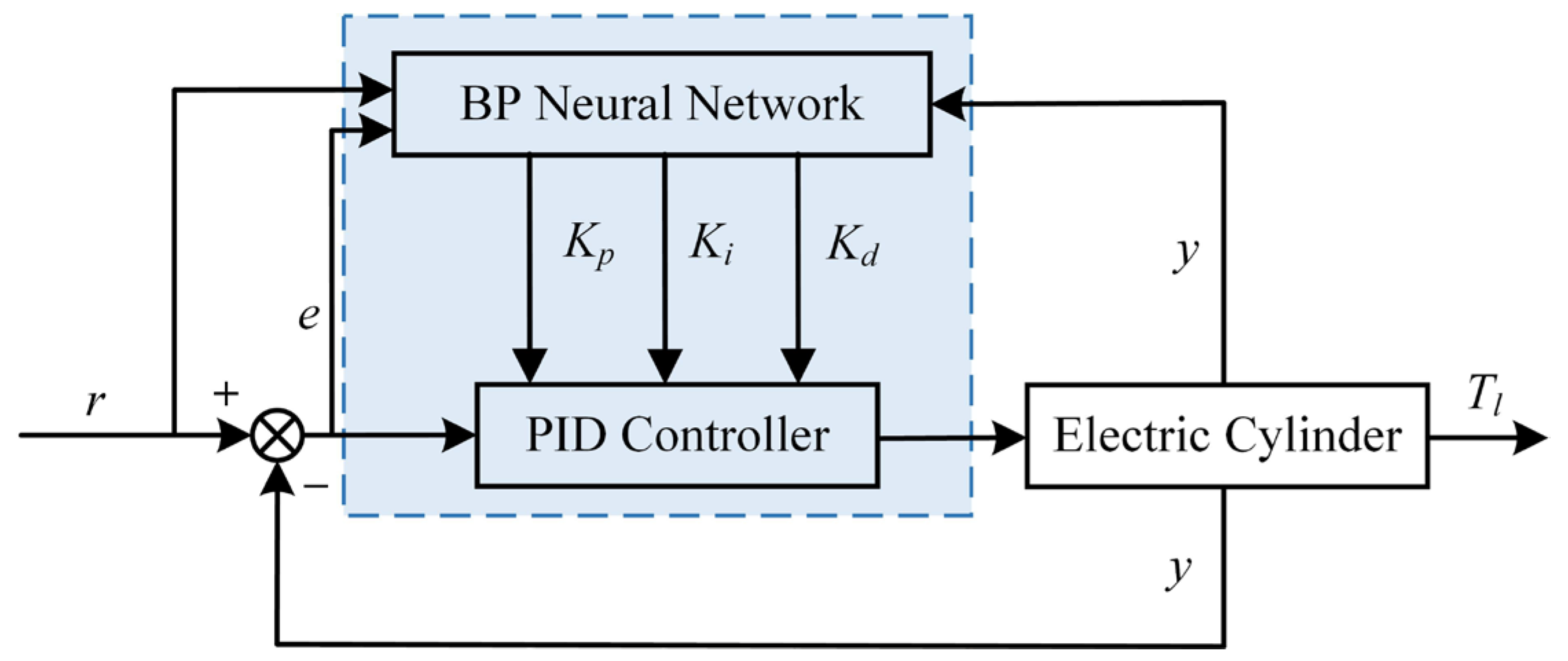
BP-PID Control Algorithm
The BP neural network is widely used in various applications. As a multi-layer backpropagation network, it is capable of handling complex computations, making it suitable for adaptive control tasks [
27]. It can approximate nonlinear functions with a high accuracy in theory. Hence, the BP neural network is combined with the traditional PID control algorithm, and the BP neural network is used to adaptively adjust the three values of the PID control method online, thereby improving the performance of the PID system when facing complex systems.
Figure 4 shows the structure diagram of the BP-PID control algorithm. Among them, the
r,
y, and
e of the input layer represent the expected input value, actual output value, and system deviation of the system parameters, respectively.
The BP neural network structure is represented in
Figure 5. It adopts a 3-5-3 structure. Because there are three main parameters r, y, and e that determine the PID controller input, the input layer consists of three nodes, corresponding to the three input parameters. Similarly, the output of the PID controller is closely related to the three parameters
Kp,
Ki, and
Kd, so the output layer consists of three nodes, corresponding to the three control outputs. The number of hidden layers and the number of nodes in the hidden layer will affect the performance of the neural network. In order to balance the data accuracy and training time, the number of hidden layers is set to 1 and the number of nodes in the hidden layer is set to 5 [
27]. In this study, according to the block diagram model in
Figure 3, the parameters
r,
y, and
e represent the expected motor rotation angle value, actual motor rotation angle value, and motor rotation angle deviation value, respectively. In
Figure 5,
j,
i, and
l represent the input, hidden, and output layers, respectively. The output is the
Kp,
Ki, and
Kd values of the PID control algorithm.
The mathematical expression of the three-layer structure is as follows. Among them, the input layer formula input layer is written as Equation (26).
The input layer formula of the hidden layer is written as Equation (27).
where
is the weighting coefficient.
The output layer formula of the hidden layer is written as Equation (28).
The bipolar S-shaped function is used as the activation function of the hidden layer neurons. It is given in Equation (29).
The algorithm for deriving the weight constant of the neural network output layer is given in Equation (30).
The algorithm for obtaining the hidden layer weight coefficient is given in Equation (31).
The three neuron node outputs of the output layer, respectively, correspond to the three adjustable values in the PID control algorithm: Kp, Ki, and Kd.
A unipolar non-negative Sigmoid function is used as the activation function of the output layer neurons. It is given in Equation (35).
During the transmission process, there is also a reverse transmission between the output and correction layer. The performance function is given in Equation (36).
Adding the momentum term formula will lower the network’s sensitivity to local details, thereby reducing the risk of the network trapping in local minimum and quickly finding the global minimum. The following formula can be used in Equation (37).
where
is the momentum term, and
η is the learning rate–their range is between 0 and 1.
k is the number of learning times. The differential expansion is written as Equation (38).
Among them, since the model is unknown,
is unknown. However, the relative changes of
u(k) and
y(k) can be predicted, which are given in Equation (39).
The above formula can be approximately replaced by the symbolic function .
The neural network output layer weight algorithm is given in Equations (40) and (41).
The hidden layer weighted learning algorithm is given in Equations (42) and (43).
4. Simulation Results and Discussions
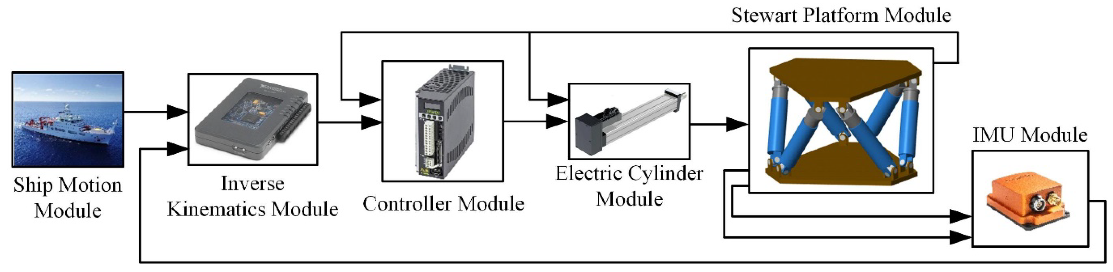
To validate the effectiveness of the shipborne Stewart platform control method based on the proposed BP-PID control algorithm in comparison with the traditional PID control algorithm, a detailed dynamic model of the shipboard Stewart platform, actuator, and control algorithm was established in MATLAB/Simulink R2023b, as shown in
Figure 6. The relevant parameters of the Stewart platform and actuator are listed in the
Table 1. The control objective of this study is to keep the top platform stationary relative to the inertial coordinate system. The motion compensation error is defined as the deviation in both the position and orientation of the top platform relative to the inertial coordinate system, which serves as the performance metric for evaluating the control algorithms.
Among the 6-DOF motion generated by the ship, the surge, sway, and yaw can all be compensated for with the help of the ship’s own dynamic positioning or anchoring technology [
28]. Therefore, this article only discusses the motion control and compensation in the roll, pitch, and heave directions. In practice, the motion of the ship in three directions is measured by IMU sensors. The Transform Sensor in Simulink can be used to detect the posture of the moving coordinate system relative to the base coordinate system. Therefore, the Transform Sensor is used as the IMU in the simulation. The actual shipborne Stewart wave compensation platform is relatively large in size. In order to verify the feasibility of the proposed algorithm in the laboratory in the future, a scaled model needs to be established. At the same time, in order to better compare the simulation data with the experimental data, we establish a scaled size model in the simulation. The reduced dimensions are as shown in the
Table 1. The corresponding sea state data have also been scaled down.
To describe the compensation effect of the shipboard Stewart platform control method, the root mean square error (RMSE) of the position and attitude is used to represent the deviation, while the corresponding speed deviation indicates smoothness [
5], as shown in Equation (44).
4.1. Regular Wave Case
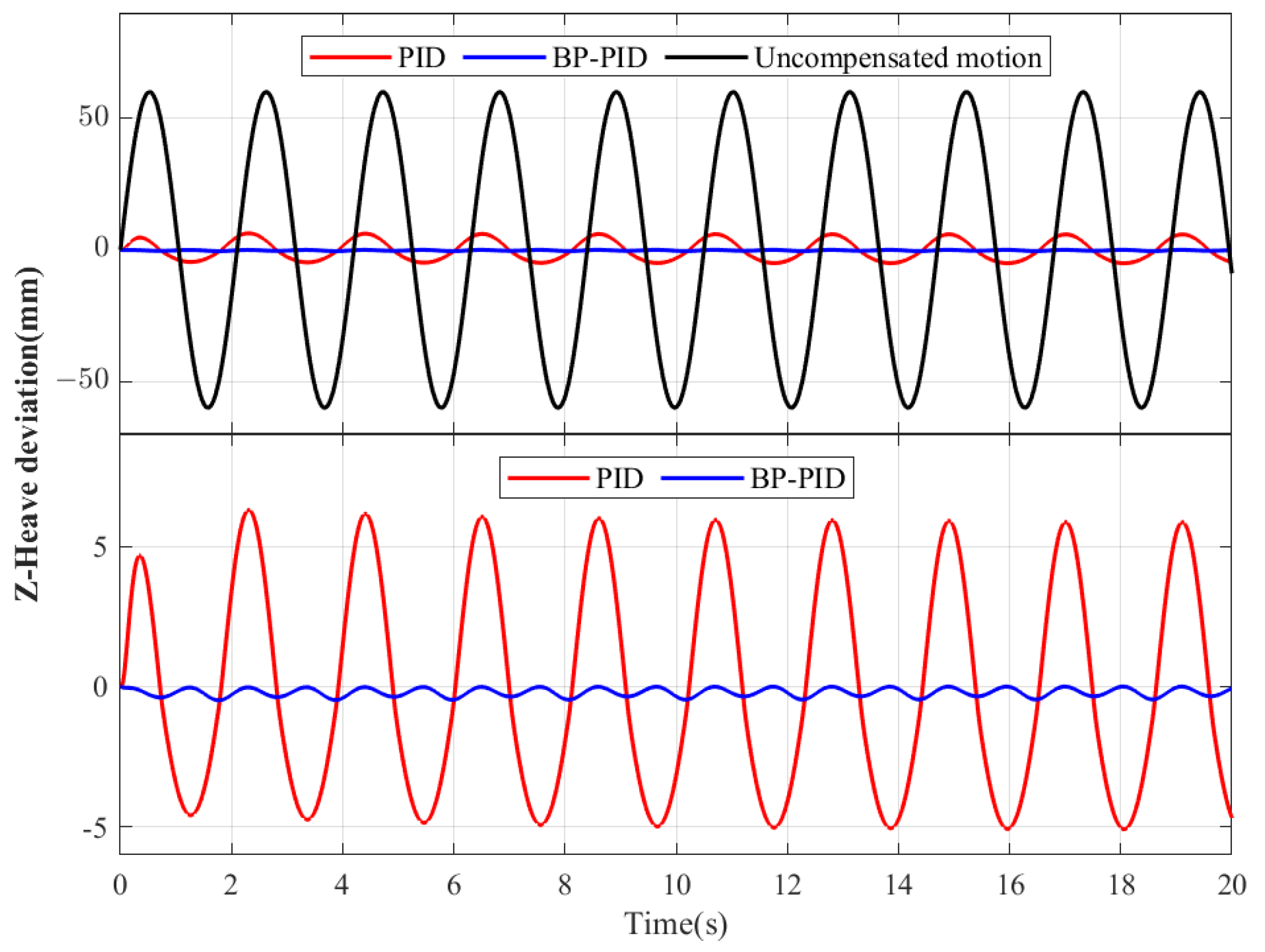
To illustrate the wave compensation effect of the new control method under sine wave signals, the simulated sine disturbances of the vessel in the three directions of heave, roll, and pitch are as follows: , , and .
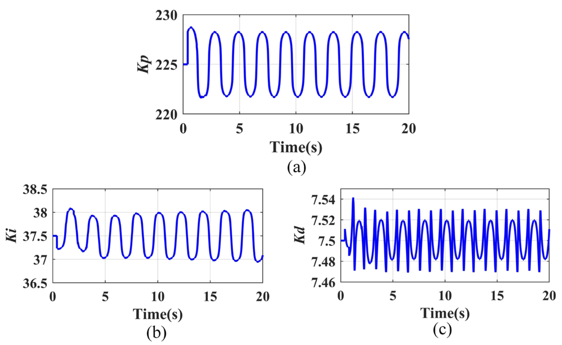
The trial-and-error method is a commonly used method for PID parameter tuning [
27]. In this work, after sufficient tuning, three values are selected for the PID control algorithm as follows:
Kp = 225,
Ki = 37.5, and
Kd = 7.5. Similarly, the learning rate
and momentum term
were repeatedly tried to ensure a balance between the convergence speed and stability of the neural network. Ultimately, the learning rate was chosen to be 0.1 and the momentum term was chosen to be 0.3.
Figure 7 shows the adjustment process of control algorithm parameters in the BP-PID control algorithm.
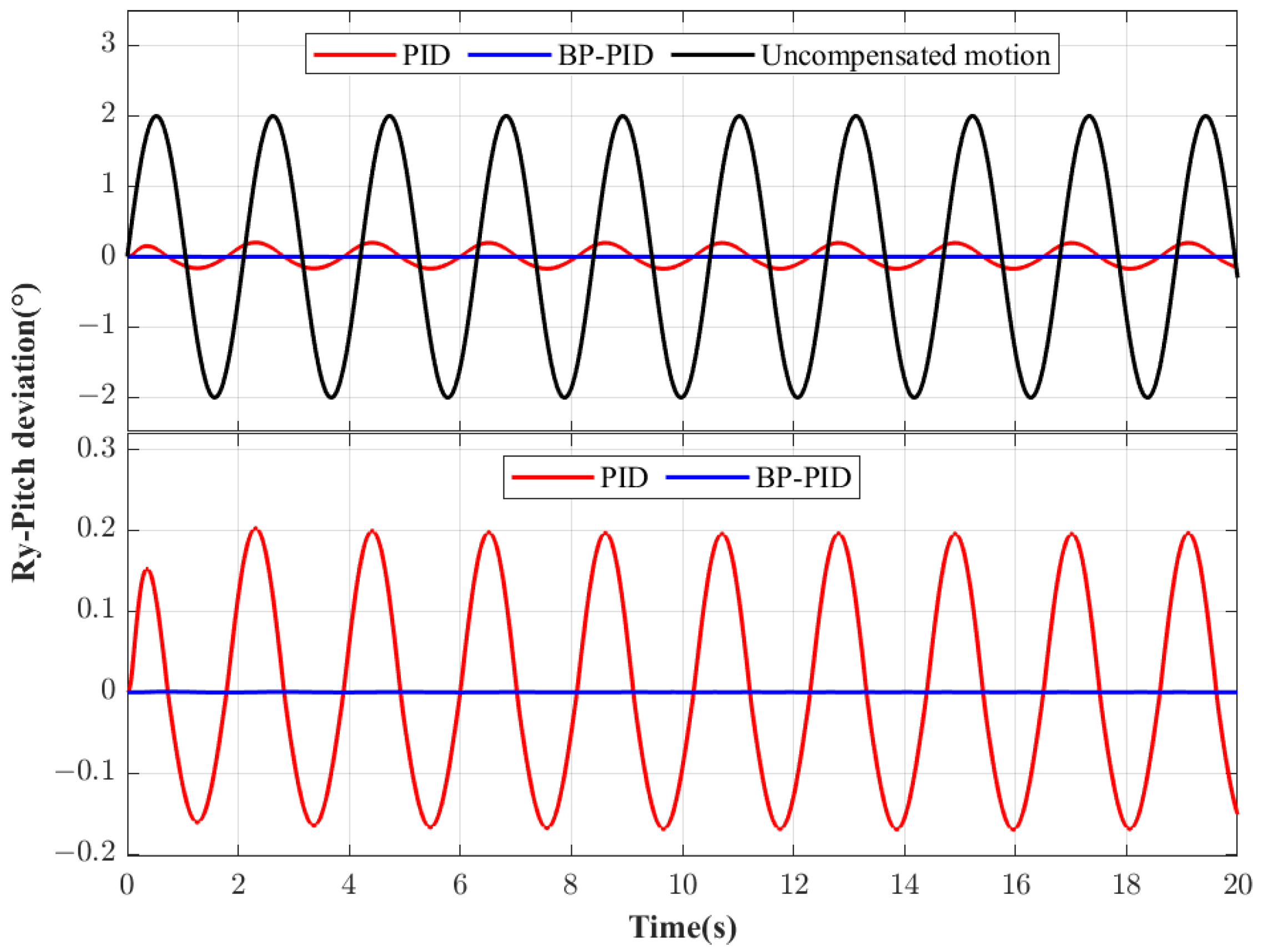
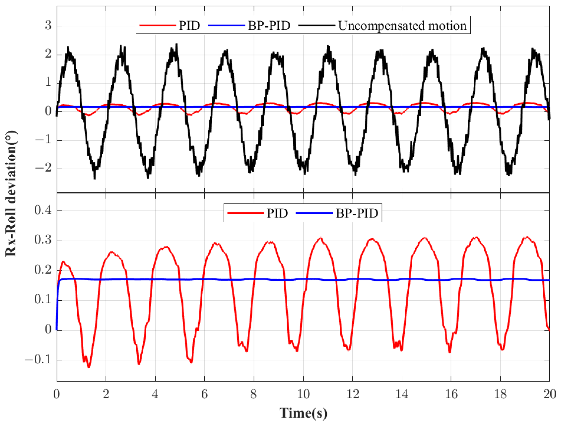
Figure 8,
Figure 9 and
Figure 10 show the motion deviation in three directions of the Stewart compensation platform using the proposed control algorithm and the PID control algorithm. In figures, the black line denotes the actual movement of the upper platform without motion compensation, which also reflects the disturbance caused by the lower platform. The blue line illustrates the compensation deviation of the upper platform using the wave compensation method proposed in this paper, while the red line shows the compensation deviation when using the traditional wave compensation method. It can be seen from the figure that both control strategies have positive effects on ship disturbance compensation. When using the PID control algorithm, the RMSE in the three directions of heave, pitch and roll is 4.009 mm, 0.1331°, and 0.1415°. When using the proposed control algorithm, the RMSE in the three directions of heave, pitch, and roll is 0.2586 mm, 1.7209 × 10
−4°, and 3.8549 × 10
−4°. From the simulation results, it can be concluded that the proposed control method can reduce the position deviation by 14.5 times and the attitude deviation is much smaller than the PID control method. The accuracy of the control system is influenced by the values of the three PID control parameters. In the traditional PID algorithm, these parameters remain fixed, whereas the newly proposed method utilizes BP to adjust the parameters based on the actual environment. This dynamic adjustment enhances control accuracy and improves the performance of heave compensation. The simulation conditions are ideal and the error is small, but it is enough to show that the control accuracy of BP-PID is better than that of the PID control method.
4.2. Irregular Wave Case
The actual movement of waves is mostly irregular, so it is necessary to prove the compensation effect of the proposed control algorithm on random signals. The Marine System Simulator (MSS) toolbox of MATLAB is used to generate the random signal of disturbance caused by ship motion through random wave theory [
29]. Among them, specific parameter information such as ships and sea conditions are shown in the
Table 2.
The sequence used to simulate ship motion is listed. The simulated ship motion sequence is shown in
Figure 11. The actual shipborne wave compensation platform is relatively large. To verify the control algorithm proposed in the laboratory, a small-scale model will be built in the future. At the same time, to better compare the simulation and experimental data, the model we built in the simulation is a small-scale model. If we continue to use the motion data obtained by MSS, the motion of the Stewart platform will be limited by the size of the small-scale Stewart platform. Therefore, the Z-direction motion amplitude applied to the base platform of the Stewart platform was scaled down 10 times during the simulation, while the roll and pitch direction amplitudes remained unchanged.
Figure 12 shows the adjustment process of control algorithm parameters in the BP-PID control algorithm.
Figure 13,
Figure 14 and
Figure 15 show the motion deviation in three directions of the Stewart compensation platform using two control algorithms. We can see that both control strategies have positive results on ship disturbance compensation. When using the PID control algorithm, the RMSE in the three directions of heave, pitch, and roll is 0.85 mm, 0.045°, and 0.0283°. When using the proposed control algorithm, the RMSE in the three directions of heave, pitch, and roll is 0.1123 mm, 0.035°, and 0.0241°. It can be concluded from the simulation results that the maximum value of the residual motion based on BP is smaller than that of the PID control algorithm. The proposed control method can reduce the position deviation by 6.56 times, and attitude deviation in two directions by 0.28 times and 0.174 times. Although the RMSE of the proposed control method and the PID control algorithm are almost equal in both the roll and pitch directions, the error of the proposed control method is stable near a certain value, while the error of the PID control algorithm fluctuates greatly around this value. Therefore, the shipborne Stewart platform using the proposed control method is more stable in the roll and pitch directions. This further verifies the superiority of the method proposed in this paper.
4.3. Regular Wave Case with Noise
Actual sea conditions and measured signals have noise, and the Gaussian noise signal is added on the basis of the sine wave operating condition.
The variance of the Gaussian noise signal in the heave, roll, and pitch direction are 10%, 1%, and 1% of the original amplitude, respectively.
Figure 16,
Figure 17 and
Figure 18 show the motion deviation in three directions of the Stewart compensation platform using the proposed control algorithm and the PID control algorithm. We can see that both control strategies have positive effects on ship disturbance compensation. When using the PID control algorithm, the RMSE in the three directions of heave, pitch, and roll is 3.87 mm, 0.2183°, and 0.2023°. When using the proposed control algorithm, the RMSE in the three directions of heave, pitch, and roll is 0.2821 mm, 0.17°, and 0.1699°. The simulation results show that the maximum error value based on BP is smaller than that of the PID control algorithm. The new control method can reduce the position deviation by 12.72 times, and attitude deviation by 0.26 times and 0.17 times. The error of the proposed control method is stable near a certain value, while the error of the PID control algorithm fluctuates greatly around this value. Therefore, the shipborne Stewart platform using the proposed control method is more stable in the roll and pitch directions.
4.4. Irregular Wave Case with Noise
The Gaussian noise signal is added on the basis of the irregular wave operating condition. The variance of the Gaussian noise signal in the heave, roll, and pitch direction are 10%, 1%, and 1% of the original amplitude, respectively.
Figure 19,
Figure 20 and
Figure 21 show the motion deviation in three directions of the Stewart compensation platform using the proposed control algorithm and the PID control algorithm. It can be seen from the figure that both control strategies have positive effects on ship disturbance compensation. When using the PID control algorithm, the RMSE in the three directions of heave, pitch, and roll is 0.7846 mm, 0.0686°, and 0.0741°. When using the control algorithm proposed in this article, the RMSE in the three directions of heave, pitch, and roll is 0.1108 mm, 0.0651°, and 0.0714°. The simulation results show that the maximum error value based on BP is smaller than that of the PID control algorithm. Compared with the traditional method, the proposed control method can reduce the position deviation by 6.08 times, and attitude deviation by 0.09 times and 0.08 times. The error of the proposed control method is stable near a certain value, while the error of the PID control algorithm fluctuates greatly around this value. Therefore, the shipborne Stewart platform using the proposed control method is more stable in the roll and pitch directions. The results further confirm the superiority of the proposed method has a higher control accuracy under complex working conditions than the PID method.


