

A Study on Welding Sensitivity Assessment and Deformation Control of International Maritime Organization Type C Liquefied Natural Gas Fuel Tank Support Structures Using the Direct Inherent Strain Method


Abstract
1. Introduction
2. Fuel Tank Systems
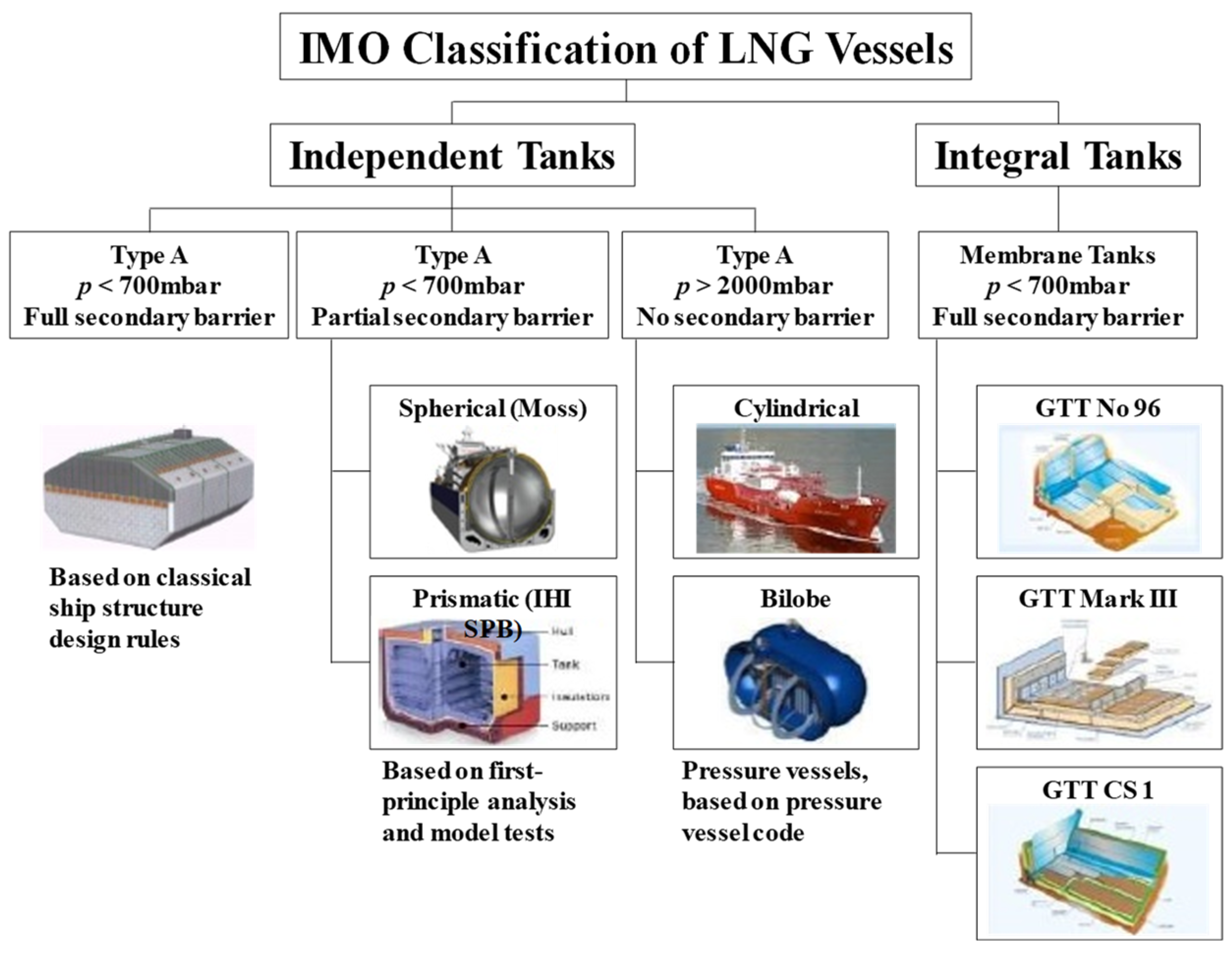
2.1. Types of Fuel Tank Systems
2.2. IMO Type C Fuel Tank System
3. Evaluation Overview
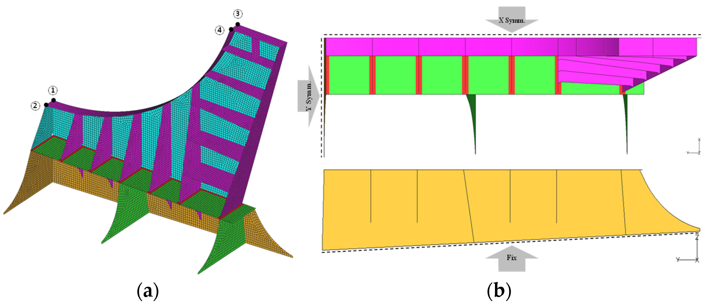
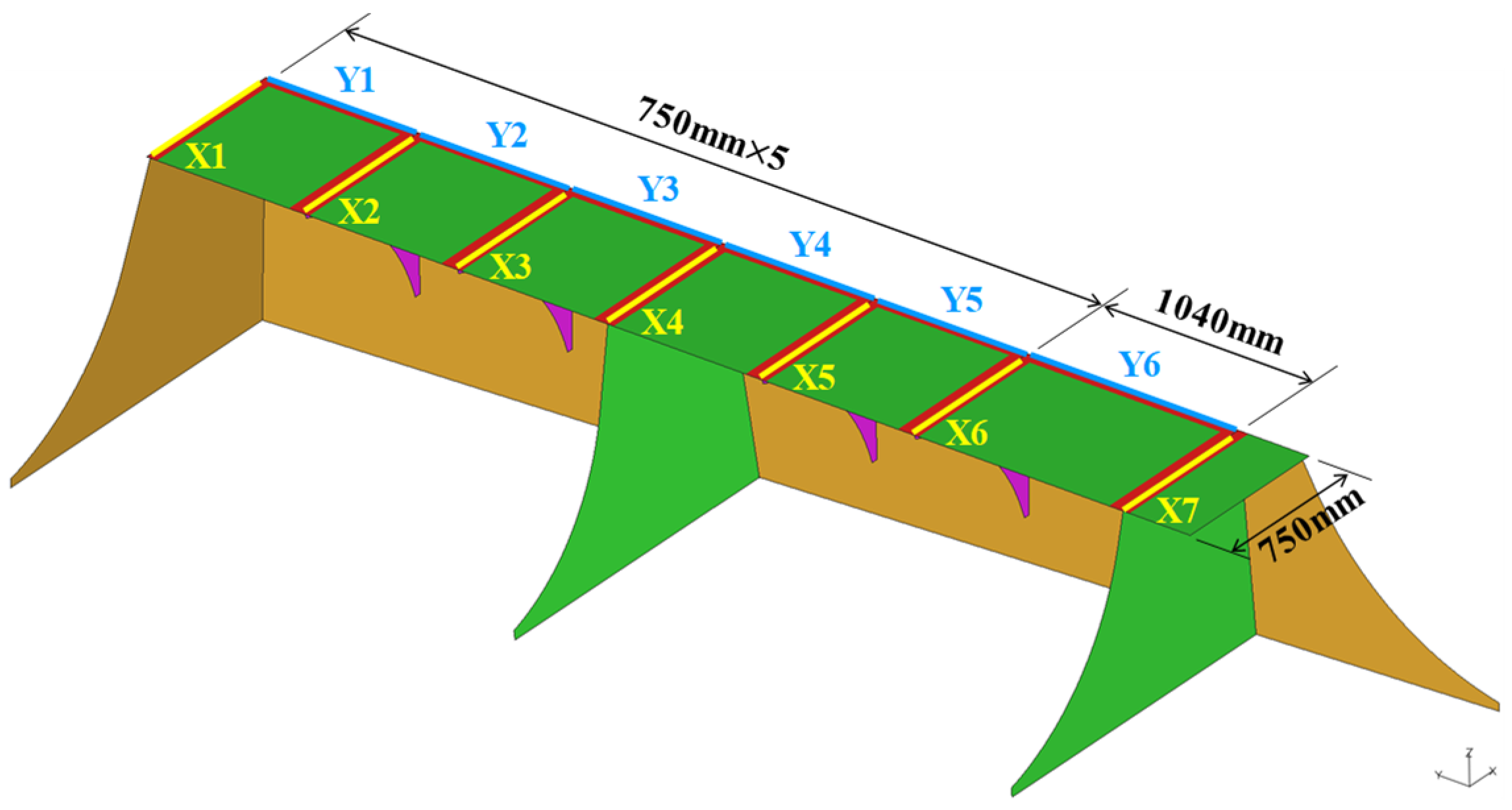
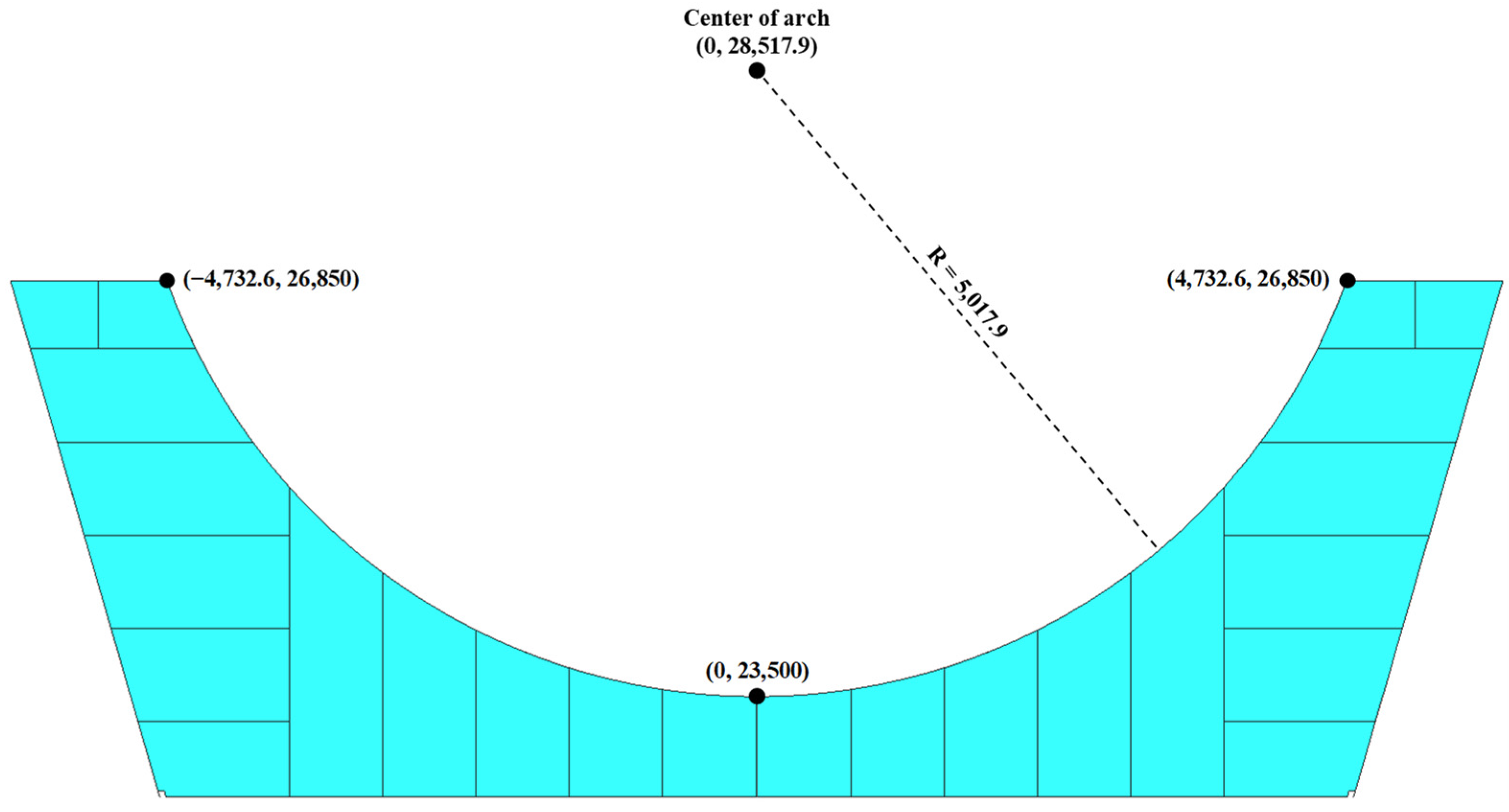
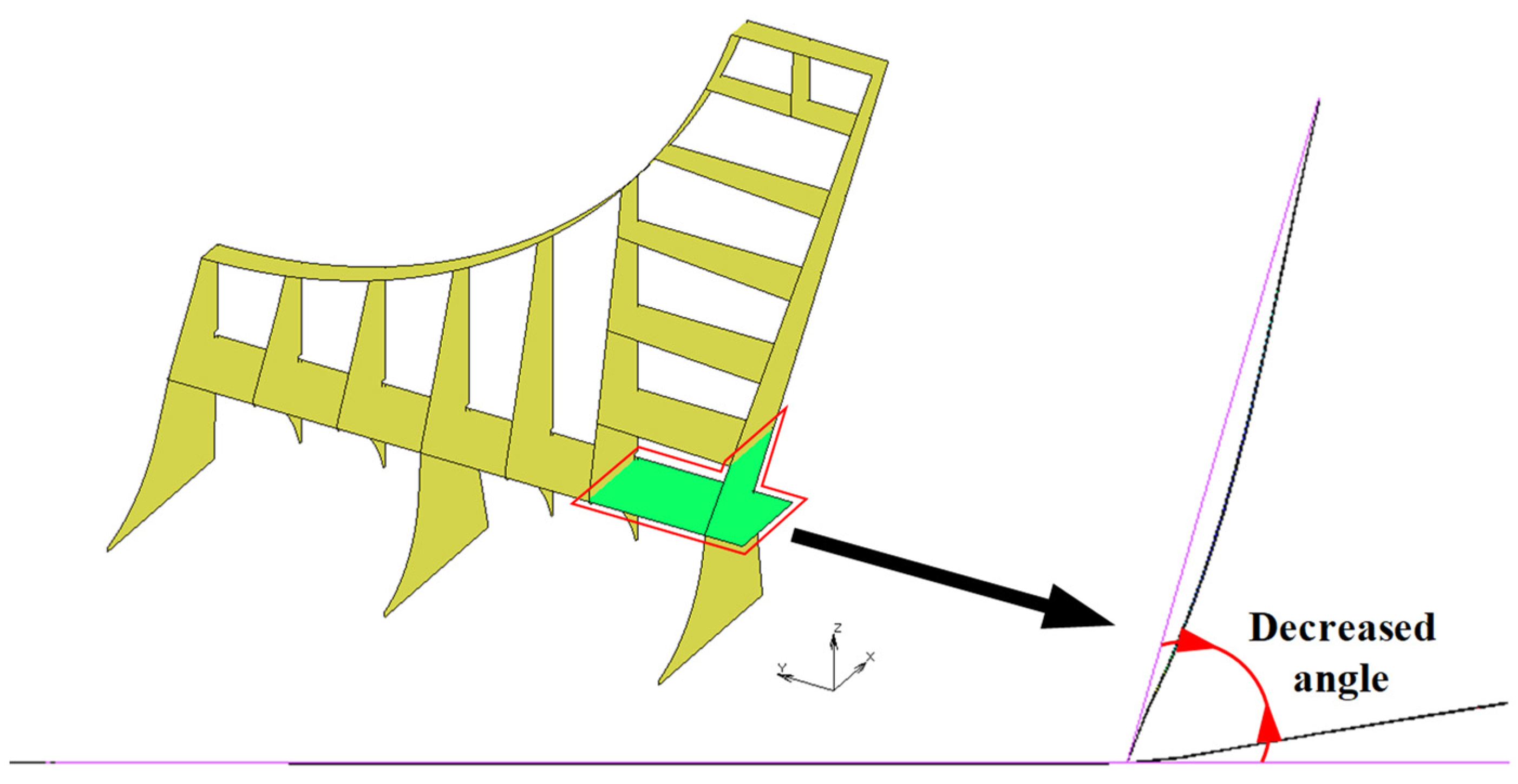
3.1. Evaluation Target and Analysis Model
3.2. Evaluation Method
3.3. Sensitivity Evaluation
3.4. Welding Deformation Analysis Conditions
- Welding the saddle to the hull first, followed by mounting the pressure vessel.
- Temporarily mounting the pressure vessel on the saddle, welding the saddle to the hull, and then fully mounting the pressure vessel.
- Installing an integrated tank–saddle fuel tank system.
4. Results and Discussion
4.1. Sensitivity Evaluation Results
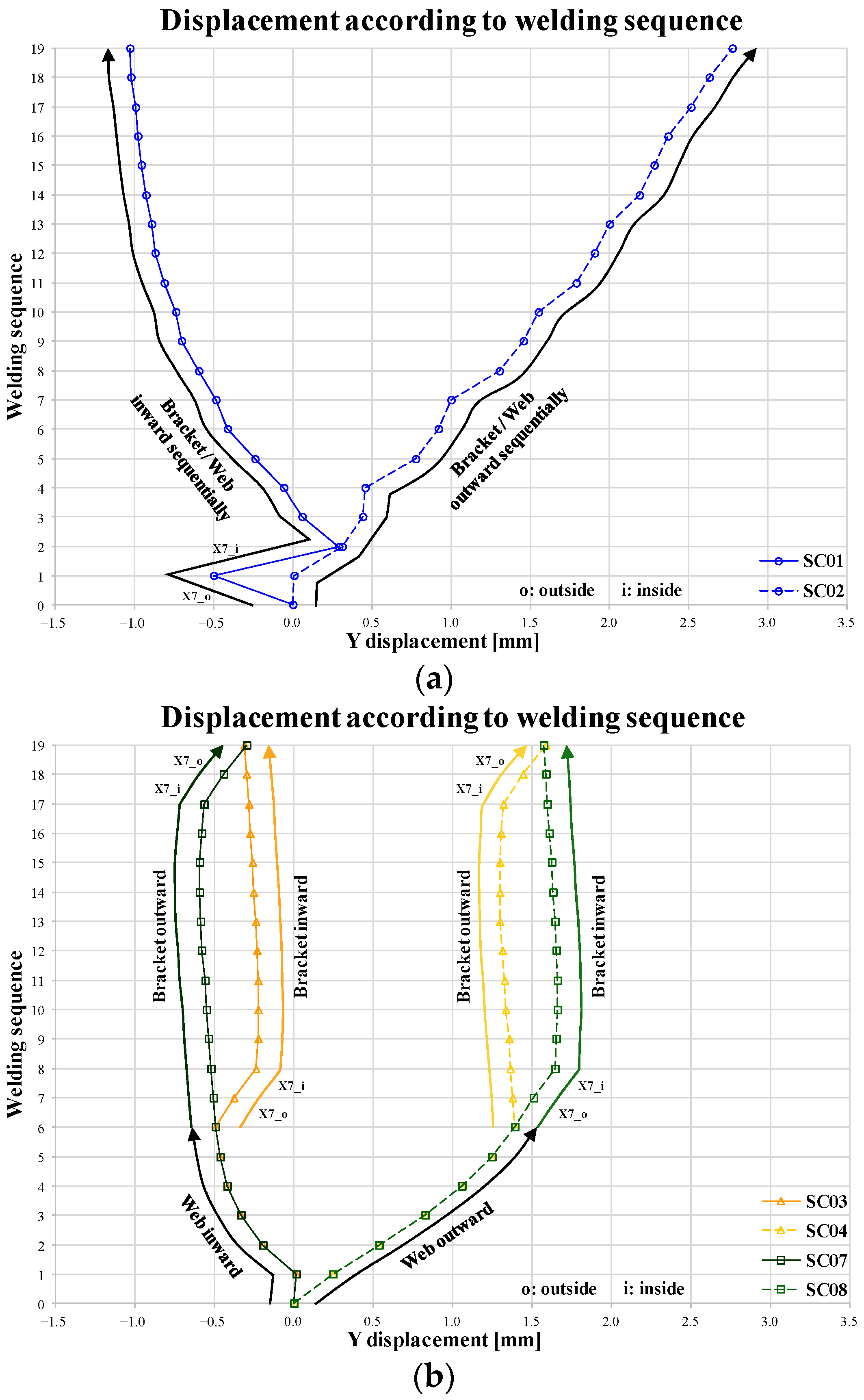
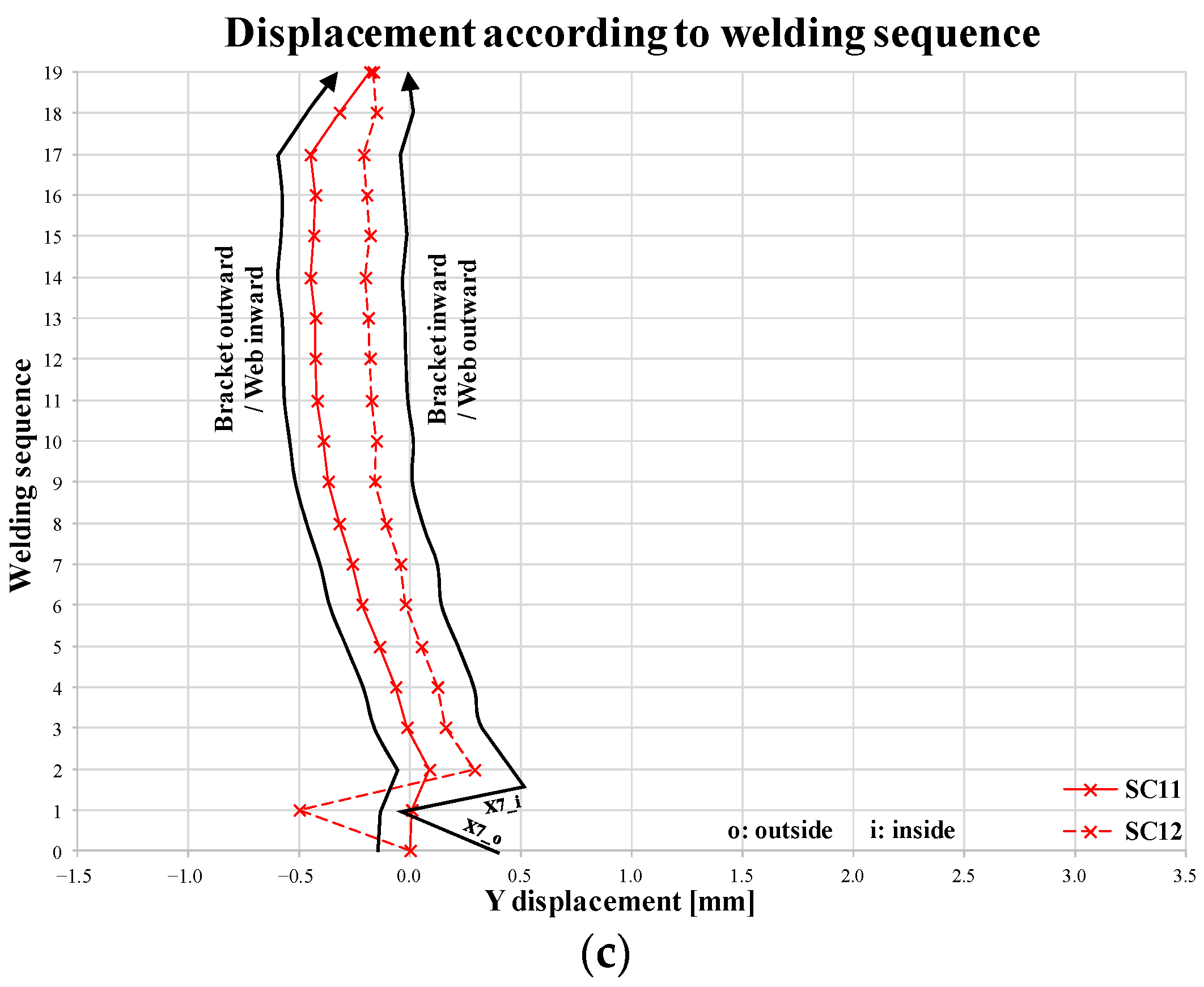
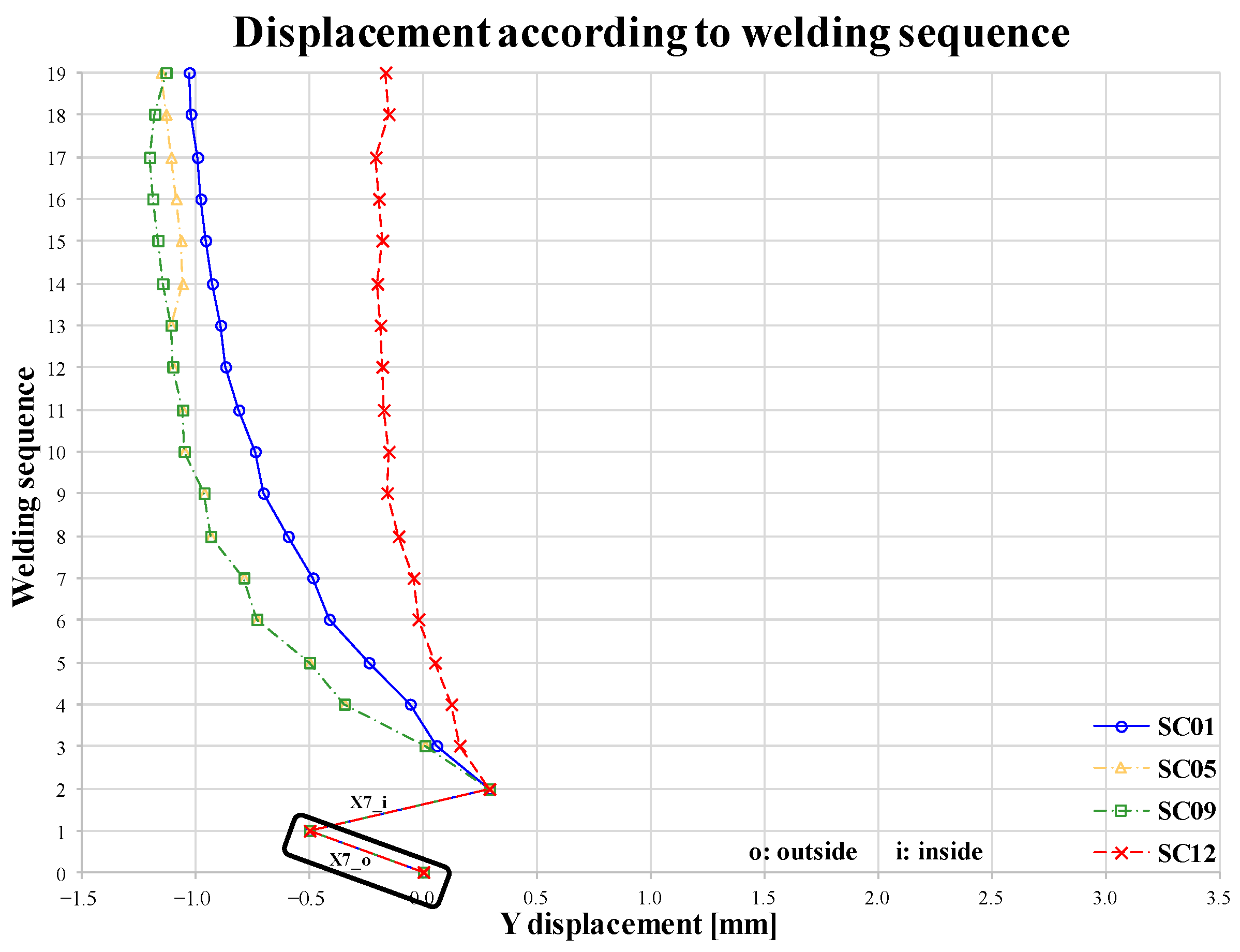
4.2. Welding Deformation Analysis Results
- Scenarios 1 and 2: These scenarios offer excellent workability, as the saddle’s bracket and web frame are welded alternately in the same direction.
- Scenarios 3, 4, 5, and 6: These scenarios have average workability. While the bracket and web frame are welded in the same direction, the work path is retraced after welding the bracket or web frame, and welding is then performed again in the same direction.
- Scenarios 7, 8, 9, and 10: These scenarios also exhibit good workability, where the bracket or web frame is welded in sequence, and the remaining welding is completed by retracing the previously covered work path.
- Scenarios 11 and 12: These scenarios have the poorest workability, as the bracket and web frame are alternately welded at precisely opposite positions.
- Scenarios 1 and 2 offer the best workability but result in moderate-to-large deformation.
- Scenarios 3, 4, 5, and 6 provide good workability, with deformation ranging from moderate to maximum.
- Scenarios 7, 8, 9, and 10 have average workability, inducing deformation from small to large.
- Scenarios 11 and 12 exhibit the worst workability but cause the least deformation.
5. Conclusions
- Sensitivity analysis of all weld lines on the saddle’s bracket and web frame revealed that the weld lines located on the outer side of the saddle exhibit the highest sensitivity to welding deformation.
- Based on the sensitivity analysis, twelve welding sequence scenarios were developed for sequential fillet welding. The study confirmed the differences in deformation behavior and the extent of saddle deformation depending on the welding direction and sequence.
- A quantitative and qualitative classification of welding deformation and workability was provided, offering a range of options tailored to specific needs.
Author Contributions
Funding
Institutional Review Board Statement
Informed Consent Statement
Data Availability Statement
Conflicts of Interest
References
- Pfoser, S.; Schauer, O.; Costa, Y. Acceptance of LNG as an Alternative Fuel: Determinants and Policy Implications. Energy Policy 2018, 120, 259–267. [Google Scholar] [CrossRef]
- Huan, T.; Hongjun, F.; Wei, L.; Guoqiang, Z. Options of Evaluations on Propulsion Systems of LNG Carriers. In Propulsion Systems; Intech Open: Wuhan, China, 2019; pp. 1–20. [Google Scholar] [CrossRef]
- ASME (The American Society of Mechanical Engineers). ASME BPVC Sec. VIII 1-2017. Available online: https://abodama.com/wp-content/uploads/2021/05/ASME-BPVC-Section-VIII.pdf (accessed on 1 July 2017).
- IGF Code (International Code of Safety for Ship Using Gases or Other Low-flashpoint Fuels). MSC 95/22/Add. 1 Annex 1 6.4.15.3.1.1. Available online: https://www.register-iri.com/wp-content/uploads/MSC_Resolution_39195.pdf (accessed on 11 June 2015).
- Oliveira, A.S.; Santos, R.O.; Silva, B.C.S.; Guarieiro, L.L.N.; Angerhausen, M.; Reisgen, U.; Sampaio, R.R.; Machado, B.A.S.; Droguett, E.L.; Silva, P.H.F.; et al. A Detailed Forecast of the Technologies Based on Lifecycle Analysis of GMAW and CMT Welding. Process. Sustain. 2021, 13, 3766. [Google Scholar] [CrossRef]
- Galic, H.; Slapnicar, V.; Rudan, S. Design of lng tank Type C. Machines 2023, 17, 244–254. [Google Scholar]
- Svilicic, S.; Rudan, S.; Galic, H.; Weigand, E.; Slapnicar, V. Comparative FEM Analysis of Vacuum and Perlite Insulation Techniques on the Structural Integrity of Independent Type C Liquefied Natural Gas Tank. J. Mar. Sci. Eng. 2024, 12, 1027. [Google Scholar] [CrossRef]
- Wang, B.; Shin, Y.S.; Wang, X. Structural Integrity Assessment of Independent Type ‘C’ LNG Carriers. In Proceedings of the ASME 2014 33rd International Conference on Ocean, Offshore and Arctic Engineering, San Francisco, CA, USA, 8–13 June 2014; p. V04BT02A032. [Google Scholar] [CrossRef]
- Milioulis, K.; Bolbot, V.; Theotokatos, G. Model-Based Safety Analysis and Design Enhancement of a Marine LNG Fuel Feeding System. J. Mar. Sci. Eng. 2021, 9, 69. [Google Scholar] [CrossRef]
- Kim, B.I.; Kim, K.T.; Islam, S. Development of Strength Evaluation Methodology for Independent IMO TYPE C Tank with LH2 Carriers. J. Ocean. Eng. Technol. 2024, 38, 87–102. [Google Scholar] [CrossRef]
- Li, C.B.; Choung, J. Numerical and Experimental Study on Sloshing Impact Loads in IMO Type-C LNG Tanks with Different Swash Bulkheads. Pract. Des. Ships Other Float. Struct. 2019, 63, 1046–1055. [Google Scholar] [CrossRef]
- Nam, K.S.; Kim, T.J. Study on the Optimum Design Pressure of IMO Type C Liquefied Hydrogen Tank Considering Fracture Mechanics and Boil off Gas Accumulation. In Proceedings of the 33rd International Ocean and Polar Engineering Conference, Ottawa, ON, Canada, 19–23 June 2023; p. ISOPE-I-23-497. [Google Scholar]
- Ye, C.; Lin, Y.; Pei, F. Comparative study of three insulation materials installed on type C independent tank for offshore LNG transportation. Cryogenics 2022, 126, 103521. [Google Scholar] [CrossRef]
- Chen, L.; Zhang, S.; Han, Y. Optimization of Saddle Structure of Type C LNG Fuel Tanks Transversely Arranged in Large Container Ships. J. Ship Boat 2023, 34, 63. [Google Scholar]
- Oh, J.H. Analytical Validation of an Alternative Analysis Method for IMO Type C Tank Substructure. In Proceedings of the 34th International Ocean and Polar Engineering Conference, Rhodes, Greece, 16–21 June 2024; p. ISOPE-I-24-487. [Google Scholar]
- Wu, S.; Ju, Y. Numerical study of the boil-off gas (BOG) generation characteristics in a type C independent liquefied natural gas (LNG) tank under sloshing excitation. Energy 2021, 223, 120001. [Google Scholar] [CrossRef]
- Ha, Y.S.; Jang, C.D. An Improved Inherent Strain Analysis for Plate Bending by Line Heating Considering Phase Transformation of Steel. Int. J. Offshore Polar Eng. 2007, 17, 139–144. [Google Scholar]
- Lin, Y.; Ye, C.; Yu, Y.; Bi, S. An approach to estimating the boil-off rate of LNG in type C independent tank for floating storage and regasification unit under different filling ratio. Appl. Therm. Eng. 2018, 135, 463–471. [Google Scholar] [CrossRef]
- Lee, D.H.; Seo, J.K.; Yi, M.S.; Hyun, C.M. Welding Distortion Characteristics of Door Openings According to Changing Shape of Stiffener. J. Ocean Eng. Technol. 2019, 33, 153–160. [Google Scholar] [CrossRef]
- Ha, Y. A Study on Weldment Boundary Condition for Elasto-Plastic Thermal Distortion Analysis of Large Welded Structures. J. Korean Weld. Join. Soc. 2011, 29, 410–415. [Google Scholar]
- Qu, Y.; Chen, J.; Jiao, L.; Ye, T.; Hu, X. Experiment and finite element analysis of protective honeycombs based on equivalent method for ocean engineering under impact loading. Compos. Struct. 2024, 331, 117858. [Google Scholar] [CrossRef]
- Ha, Y. Development of Thermal Distortion Analysis Method on Large Shell Structure Using Inherent Strain as Boundary Condition. J. Soc. Nav. Archit. Korea 2008, 45, 93–100. [Google Scholar] [CrossRef]
- Ha, Y. Analytical Methodology Obtaining an Optical Welding Sequence for Least Distortion of Welded Structure. J. Korean Weld. Join. Soc. 2013, 31, 54–59. [Google Scholar]
- Wu, C.; Kim, J.W. Numerical prediction of deformation in thin-plate welded joints using equivalent thermal strain method. Thin-Walled Struct. 2020, 157, 107033. [Google Scholar] [CrossRef]
- Yao, Y.; Ai, Y.; Guan, P.; Tian, J.; Bao, T.; Hu, X.; Wu, C. Minimum life point determination and fatigue life prediction of thermal barrier coatings based on extended stress and strain method. Int. J. Fatigue 2024, 186, 108419. [Google Scholar] [CrossRef]


| Item | Material |
|---|---|
| Pressure vessel | 9% nickel |
| Wooden block | Laminated wood |
| Load bearing | Epoxy resin |
| Saddle | DH36 |
| Seat (hull part) | DH36 |
| Target | Weld Line | Y Disp. [mm] | Ave. Difference of Y Disp. ③, ④ [mm] | Sensitivity Ranking | Absolute δ/δ min | Welding Sequence | ||
|---|---|---|---|---|---|---|---|---|
| ③ | ④ | Most Inward Deformation | ||||||
| X1 | w/o X1 | −0.156 | −0.156 | −0.013 | 5 | 1.2 | X7 | Y3 |
| X1 | −0.143 | −0.143 | ||||||
| X2 | w/o X2 | −0.166 | −0.166 | −0.021 | 8 | 1.9 | Y6 | Y4 |
| X2 | −0.145 | −0.145 | ||||||
| X3 | w/o X3 | −0.152 | −0.152 | −0.020 | 7 | 1.8 | X6 | Y2 |
| X3 | −0.132 | −0.132 | ||||||
| X4 | w/o X4 | −0.121 | −0.121 | −0.029 | 9 | 2.7 | X5 | Y1 |
| X4 | −0.093 | −0.093 | ||||||
| X5 | w/o X5 | −0.111 | −0.111 | −0.011 | 4 | 1.0 | X1 | X4 |
| X5 | −0.100 | −0.100 | ||||||
| X6 | w/o X6 | −0.105 | −0.105 | 0.022 | 3 | 2.0 | Y5 | X2 |
| X6 | −0.127 | −0.127 | ||||||
| X7 | w/o X7 | −0.088 | −0.088 | 0.349 | 1 | 32.5 | X3 | X3 |
| X7 | −0.438 | −0.438 | ||||||
| Y1 | w/o Y1 | −0.166 | −0.166 | −0.046 | 10 | 4.3 | X2 | Y5 |
| Y1 | −0.120 | −0.120 | ||||||
| Y2 | w/o Y2 | −0.154 | −0.154 | −0.054 | 11 | 5.0 | X4 | X1 |
| Y2 | −0.100 | −0.100 | ||||||
| Y3 | w/o Y3 | −0.141 | −0.141 | −0.067 | 13 | 6.3 | Y1 | X5 |
| Y3 | −0.074 | −0.074 | ||||||
| Y4 | w/o Y4 | −0.121 | −0.122 | −0.062 | 12 | 5.7 | Y2 | X6 |
| Y4 | −0.060 | −0.060 | ||||||
| Y5 | w/o Y5 | −0.112 | −0.112 | −0.020 | 6 | 1.8 | Y4 | Y6 |
| Y5 | −0.092 | −0.092 | ||||||
| Y6 | w/o Y6 | −0.179 | −0.179 | 0.168 | 2 | 15.6 | Y3 | X7 |
| Y6 | −0.347 | −0.347 | ||||||
| Scenario | Y Displacement [mm] | Average of Y Displacement ③, ④ [mm] | |
|---|---|---|---|
| ③ | ④ | ||
| Most inward deformation | −2.293830 | −2.293810 | −2.293820 |
| Most outward deformation | 1.938490 | 1.938510 | 1.938500 |
| Welding Sequence | SC1 | SC2 | SC3 | SC4 | SC5 | SC6 | SC7 | SC8 | SC9 | SC10 | SC11 | SC12 |
|---|---|---|---|---|---|---|---|---|---|---|---|---|
| 1 | X7_o | X1_o | Y6 | Y1 | X7_o | X1_o | Y6 | Y1 | X7_o | X1_o | X1_o | X7_o |
| 2 | X7_i | Y1 | Y5 | Y2 | X7_i | X2_i | Y5 | Y2 | X7_i | X2_i | Y6 | X7_i |
| 3 | Y6 | X2_i | Y4 | Y3 | X6_o | X2_o | Y4 | Y3 | X6_o | X2_o | X2_i | Y1 |
| 4 | X6_o | X2_o | Y3 | Y4 | X6_i | X3_i | Y3 | Y4 | X6_i | X3_i | X2_o | X6_o |
| 5 | X6_i | Y2 | Y2 | Y5 | X5_o | X3_o | Y2 | Y5 | X5_o | X3_o | Y5 | X6_i |
| 6 | Y5 | X3_i | Y1 | Y6 | X5_i | X4_i | Y1 | Y6 | X5_i | X4_i | X3_i | Y2 |
| 7 | X5_o | X3_o | X7_o | X1_o | X4_o | X4_o | X1_o | X7_o | X4_o | X4_o | X3_o | X5_o |
| 8 | X5_i | Y3 | X7_i | X2_i | X4_i | X5_i | X2_i | X7_i | X4_i | X5_i | Y4 | X5_i |
| 9 | Y4 | X4_i | X6_o | X2_o | X3_o | X5_o | X2_o | X6_o | X3_o | X5_o | X4_i | Y3 |
| 10 | X4_o | X4_o | X6_i | X3_i | X3_i | X6_i | X3_i | X6_i | X3_i | X6_i | X4_o | X4_o |
| 11 | X4_i | Y4 | X5_o | X3_o | X2_o | X6_o | X3_o | X5_o | X2_o | X6_o | Y3 | X4_i |
| 12 | Y3 | X5_i | X5_i | X4_i | X2_i | X7_i | X4_i | X5_i | X2_i | X7_i | X5_i | Y4 |
| 13 | X3_o | X5_o | X4_o | X4_o | X1_o | X7_o | X4_o | X4_o | X1_o | X7_o | X5_o | X3_o |
| 14 | X3_i | Y5 | X4_i | X5_i | Y6 | Y1 | X5_i | X4_i | Y1 | Y6 | Y2 | X3_i |
| 15 | Y2 | X6_i | X3_o | X5_o | Y5 | Y2 | X5_o | X3_o | Y2 | Y5 | X6_i | Y5 |
| 16 | X2_o | X6_o | X3_i | X6_i | Y4 | Y3 | X6_i | X3_i | Y3 | Y4 | X6_o | X2_o |
| 17 | X2_i | Y6 | X2_o | X6_o | Y3 | Y4 | X6_o | X2_o | Y4 | Y3 | Y1 | X2_i |
| 18 | Y2 | X7_i | X2_i | X7_i | Y2 | Y5 | X7_i | X2_i | Y5 | Y2 | X7_i | Y6 |
| 19 | X1_o | X7_o | X1_o | X7_o | Y1 | Y6 | X7_o | X1_o | Y6 | Y1 | X7_o | X1_o |
| Workability | Very good | Normal | Good | Very bad | ||||||||
| Y Displacement [mm] | Position | |||
|---|---|---|---|---|
| ① | ② | ③ | ④ | |
| SC1 | 0 | 0 | 1.031 | 1.031 |
| SC2 | 0 | 0 | −2.775 | −2.775 |
| SC3 | 0 | 0 | 0.312 | 0.312 |
| SC4 | 0 | 0 | −1.584 | −1.584 |
| SC5 | 0 | 0 | 1.154 | 1.154 |
| SC6 | 0 | 0 | −2.873 | −2.873 |
| SC7 | 0 | 0 | 0.299 | 0.299 |
| SC8 | 0 | 0 | −1.572 | −1.572 |
| SC9 | 0 | 0 | 1.128 | 1.128 |
| SC10 | 0 | 0 | −2.848 | −2.848 |
| SC11 | 0 | 0 | 0.180 | 0.180 |
| SC12 | 0 | 0 | 0.168 | 0.168 |
| Z Displacement [mm] | Position | |||||
|---|---|---|---|---|---|---|
| ① | ② | ③ | ④ | ③’ | ④’ | |
| SC1 | −1.664 | −1.695 | −0.227 | −0.227 | 1.437 | 1.468 |
| SC2 | −0.102 | −0.076 | −2.658 | −2.658 | −2.556 | −2.582 |
| SC3 | −0.814 | −0.834 | −0.185 | −0.185 | 0.630 | 0.649 |
| SC4 | −0.101 | −0.107 | −1.561 | −1.561 | −1.460 | −1.454 |
| SC5 | −1.907 | −1.908 | −0.298 | −0.298 | 1.609 | 1.610 |
| SC6 | −0.117 | −0.090 | −3.037 | −3.037 | −2.920 | −2.947 |
| SC7 | −0.806 | −0.824 | −0.191 | −0.191 | 0.615 | 0.633 |
| SC8 | −0.109 | −0.118 | −1.554 | −1.554 | −1.445 | −1.437 |
| SC9 | −1.901 | −1.904 | −0.313 | −0.313 | 1.588 | 1.590 |
| SC10 | −0.124 | −0.095 | −3.022 | −3.022 | −2.897 | −2.926 |
| SC11 | −0.170 | −0.133 | −0.300 | −0.300 | −0.129 | −0.167 |
| SC12 | −0.073 | −0.083 | −0.427 | −0.427 | −0.353 | −0.343 |
| Scenario | Ellipse Shape | a ①’–③’ [mm] | b ①’–③’ [mm] | e ①’–③’ | Ovality ①’–③’ [%] | a ②’–④’ [mm] | b ②’–④’ [mm] | e ②’–④’ | Ovality ②’–④’ [%] |
|---|---|---|---|---|---|---|---|---|---|
| SC1 | Vertical | 5019.523 | 4996.500 | 0.096 | 0.229 | 5019.554 | 4996.251 | 0.096 | 0.232 |
| SC2 | Horizontal | 5017.960 | 5048.928 | 0.111 | 0.309 | 5017.934 | 5049.140 | 0.111 | 0.311 |
| SC3 | Vertical | 5018.673 | 5009.220 | 0.061 | 0.094 | 5018.693 | 5009.060 | 0.062 | 0.096 |
| SC4 | Horizontal | 5017.959 | 5035.330 | 0.083 | 0.173 | 5017.965 | 5035.281 | 0.083 | 0.173 |
| SC5 | Vertical | 5019.766 | 4993.746 | 0.102 | 0.259 | 5019.767 | 4993.737 | 0.102 | 0.259 |
| SC6 | Horizontal | 5017.975 | 5050.798 | 0.114 | 0.327 | 5017.948 | 5051.018 | 0.114 | 0.330 |
| SC7 | Vertical | 5018.665 | 5009.415 | 0.061 | 0.092 | 5018.682 | 5009.277 | 0.061 | 0.094 |
| SC8 | Horizontal | 5017.967 | 5035.134 | 0.083 | 0.171 | 5017.976 | 5035.063 | 0.082 | 0.170 |
| SC9 | Vertical | 5019.760 | 4994.059 | 0.101 | 0.256 | 5019.762 | 4994.037 | 0.101 | 0.256 |
| SC10 | Horizontal | 5017.983 | 5050.473 | 0.113 | 0.324 | 5017.954 | 5050.709 | 0.114 | 0.326 |
| SC11 | Vertical | 5018.029 | 5015.851 | 0.029 | 0.022 | 5017.992 | 5016.150 | 0.027 | 0.018 |
| SC12 | Vertical | 5017.932 | 5017.114 | 0.018 | 0.008 | 5017.942 | 5017.035 | 0.019 | 0.009 |
| Welding Sequence | Weld Line | Average of Y-Displacement ③, ④ [mm] | Weld Line | Average of Y-Displacement ③, ④ [mm] | Weld Line | Average of Y-Displacement ③, ④ [mm] |
|---|---|---|---|---|---|---|
| SC1 | SC2 | SC3 | ||||
| 0 | - | 0.000 | - | 0.000 | - | 0.000 |
| 1 | X7_outside | −0.500 | X1_outside | 0.005 | Y6 | 0.011 |
| 2 | X7_inside | 0.287 | Y1 | 0.310 | Y5 | −0.196 |
| 3 | Y6 | 0.058 | X2_inside | 0.441 | Y4 | −0.336 |
| 4 | X6_outside | −0.059 | X2_outside | 0.456 | Y3 | −0.421 |
| 5 | X6_inside | −0.240 | Y2 | 0.775 | Y2 | −0.466 |
| 6 | Y5 | −0.415 | X3_inside | 0.918 | Y1 | −0.495 |
| 7 | X5_outside | −0.489 | X3_outside | 0.998 | X7_outside | −0.380 |
| 8 | X5_inside | −0.592 | Y3 | 1.303 | X7_inside | −0.241 |
| 9 | Y4 | −0.702 | X4_inside | 1.458 | X6_outside | −0.229 |
| 10 | X4_outside | −0.742 | X4_outside | 1.553 | X6_inside | −0.223 |
| 11 | X4_inside | −0.810 | Y4 | 1.791 | X5_outside | −0.223 |
| 12 | Y3 | −0.871 | X5_inside | 1.905 | X5_inside | −0.232 |
| 13 | X3_outside | −0.894 | X5_outside | 2.002 | X4_outside | −0.237 |
| 14 | X3_inside | −0.927 | Y5 | 2.188 | X4_inside | −0.255 |
| 15 | Y2 | −0.961 | X6_inside | 2.281 | X3_outside | −0.263 |
| 16 | X2_outside | −0.976 | X6_outside | 2.367 | X3_inside | −0.276 |
| 17 | X2_inside | −0.995 | Y6 | 2.514 | X2_outside | −0.287 |
| 18 | Y1 | −1.019 | X7_inside | 2.634 | X2_inside | −0.300 |
| 19 | X1_outside | −1.031 | X7_outside | 2.775 | X1_outside | −0.312 |
| Welding Sequence | Weld Line | Ave. of Y-Disp. ③, ④ [mm] | Weld Line | Ave. of Y-Disp. ③, ④ [mm] | Weld Line | Ave. of Y-Disp. ③, ④ [mm] |
|---|---|---|---|---|---|---|
| SC4 | SC5 | SC6 | ||||
| 0 | - | 0.000 | - | - | 0.000 | |
| 1 | Y1 | 0.244 | X7_outside | Y1 | X7_outside | 0.244 |
| 2 | Y2 | 0.537 | X7_inside | Y2 | X7_inside | 0.537 |
| 3 | Y3 | 0.824 | X6_outside | Y3 | X6_outside | 0.824 |
| 4 | Y4 | 1.059 | X6_inside | Y4 | X6_inside | 1.059 |
| 5 | Y5 | 1.245 | X5_outside | Y5 | X5_outside | 1.245 |
| 6 | Y6 | 1.394 | X5_inside | Y6 | X5_inside | 1.394 |
| 7 | X1_outside | 1.379 | X4_outside | X1_outside | X4_outside | 1.379 |
| 8 | X2_inside | 1.363 | X4_inside | X2_inside | X4_inside | 1.363 |
| 9 | X2_outside | 1.352 | X3_outside | X2_outside | X3_outside | 1.352 |
| 10 | X3_inside | 1.336 | X3_inside | X3_inside | X3_inside | 1.336 |
| 11 | X3_outside | 1.328 | X2_outside | X3_outside | X2_outside | 1.328 |
| 12 | X4_inside | 1.308 | X2_inside | X4_inside | X2_inside | 1.308 |
| 13 | X4_outside | 1.301 | X1_outside | X4_outside | X1_outside | 1.301 |
| 14 | X5_inside | 1.294 | Y6 | X5_inside | Y6 | 1.294 |
| 15 | X5_outside | 1.294 | Y5 | X5_outside | Y5 | 1.294 |
| 16 | X6_inside | 1.306 | Y4 | X6_inside | Y4 | 1.306 |
| 17 | X6_outside | 1.319 | Y3 | X6_outside | Y3 | 1.319 |
| 18 | X7_inside | 1.444 | Y2 | X7_inside | Y2 | 1.444 |
| 19 | X7_outside | 1.584 | Y1 | X7_outside | Y1 | 1.584 |
| Welding Sequence | Weld Line | Ave. of Y-Disp. ③, ④ [mm] | Weld Line | Ave. of Y-Disp. ③, ④ [mm] | Weld Line | Ave. of Y-Disp. ③, ④ [mm] |
|---|---|---|---|---|---|---|
| SC7 | SC8 | SC9 | ||||
| 0 | - | 0.000 | - | - | 0.000 | - |
| 1 | Y6 | 0.011 | Y1 | Y6 | 0.011 | Y1 |
| 2 | Y5 | −0.196 | Y2 | Y5 | −0.196 | Y2 |
| 3 | Y4 | −0.336 | Y3 | Y4 | −0.336 | Y3 |
| 4 | Y3 | −0.421 | Y4 | Y3 | −0.421 | Y4 |
| 5 | Y2 | −0.466 | Y5 | Y2 | −0.466 | Y5 |
| 6 | Y1 | −0.495 | Y6 | Y1 | −0.495 | Y6 |
| 7 | X1_outside | −0.509 | X7_outside | X1_outside | −0.509 | X7_outside |
| 8 | X2_inside | −0.526 | X7_inside | X2_inside | −0.526 | X7_inside |
| 9 | X2_outside | −0.536 | X6_outside | X2_outside | −0.536 | X6_outside |
| 10 | X3_inside | −0.552 | X6_inside | X3_inside | −0.552 | X6_inside |
| 11 | X3_outside | −0.560 | X5_outside | X3_outside | −0.560 | X5_outside |
| 12 | X4_inside | −0.580 | X5_inside | X4_inside | −0.580 | X5_inside |
| 13 | X4_outside | −0.587 | X4_outside | X4_outside | −0.587 | X4_outside |
| 14 | X5_inside | −0.594 | X4_inside | X5_inside | −0.594 | X4_inside |
| 15 | X5_outside | −0.594 | X3_outside | X5_outside | −0.594 | X3_outside |
| 16 | X6_inside | −0.582 | X3_inside | X6_inside | −0.582 | X3_inside |
| 17 | X6_outside | −0.569 | X2_outside | X6_outside | −0.569 | X2_outside |
| 18 | X7_inside | −0.440 | X2_inside | X7_inside | −0.440 | X2_inside |
| 19 | X7_outside | −0.299 | X1_outside | X7_outside | −0.299 | X1_outside |
| Welding Sequence | Weld Line | Ave. of Y-Disp. ③, ④ [mm] | Weld Line | Ave. of Y-Disp. ③, ④ [mm] | Weld Line | Ave. of Y-Disp. ③, ④ [mm] |
|---|---|---|---|---|---|---|
| SC10 | SC11 | SC12 | ||||
| 0 | - | 0.000 | - | - | 0.000 | - |
| 1 | X1_outside | 0.005 | X1_outside | X1_outside | 0.005 | X1_outside |
| 2 | X2_inside | 0.390 | Y6 | X2_inside | 0.390 | Y6 |
| 3 | X2_outside | 0.431 | X2_inside | X2_outside | 0.431 | X2_inside |
| 4 | X3_inside | 0.925 | X2_outside | X3_inside | 0.925 | X2_outside |
| 5 | X3_outside | 1.102 | Y5 | X3_outside | 1.102 | Y5 |
| 6 | X4_inside | 1.483 | X3_inside | X4_inside | 1.483 | X3_inside |
| 7 | X4_outside | 1.628 | X3_outside | X4_outside | 1.628 | X3_outside |
| 8 | X5_inside | 1.953 | Y4 | X5_inside | 1.953 | Y4 |
| 9 | X5_outside | 2.142 | X4_inside | X5_outside | 2.142 | X4_inside |
| 10 | X6_inside | 2.382 | X4_outside | X6_inside | 2.382 | X4_outside |
| 11 | X6_outside | 2.550 | Y3 | X6_outside | 2.550 | Y3 |
| 12 | X7_inside | 2.665 | X5_inside | X7_inside | 2.665 | X5_inside |
| 13 | X7_outside | 2.892 | X5_outside | X7_outside | 2.892 | X5_outside |
| 14 | Y6 | 2.940 | Y2 | Y6 | 2.940 | Y2 |
| 15 | Y5 | 2.936 | X6_inside | Y5 | 2.936 | X6_inside |
| 16 | Y4 | 2.917 | X6_outside | Y4 | 2.917 | X6_outside |
| 17 | Y3 | 2.892 | Y1 | Y3 | 2.892 | Y1 |
| 18 | Y2 | 2.870 | X7_inside | Y2 | 2.870 | X7_inside |
| 19 | Y1 | 2.848 | X7_outside | Y1 | 2.848 | X7_outside |
| Welding Heat Input Condition | Step | SC5 Ave. of Y-Dis. ③, ④ [mm] | SC6 Ave. of Y-Dis. ③, ④ [mm] | Remark |
|---|---|---|---|---|
| Combined (original) | After bracket welding | −1.11 | 2.89 | SC5: Weld brackets (1st) and web frames (2nd) inward of the saddle SC6: Weld brackets (1st) and web frames (2nd) outward of the saddle |
| After web frame welding | −1.15 | 2.87 | ||
| Only Longi. shrinkage | After bracket welding | −0.32 | 0.98 | |
| After web frame welding | −0.38 | 0.98 | ||
| Only Trans. shrinkage | After bracket welding | −0.75 | 2.17 | |
| After web frame welding | −0.80 | 2.14 | ||
| Only Ang. distortion | After bracket welding | −0.37 | 0.78 | |
| After web frame welding | −0.36 | 0.78 |
| Scenario | Average of Y-Displacement ③, ④ [mm, anticlastic] | Brackets’ Welding Direction (X) | Web Frame’s Welding Direction (Y) | Absolute δ/δ min | Work-Ability | Remark |
|---|---|---|---|---|---|---|
| SC12 | −0.168 | Inward | Outward | 1.000 | Very bad | Small Displacement ↑ | | | | | | ↓ Large displacement |
| SC11 | −0.180 | Outward | Inward | 1.071 | Very bad | |
| SC07 | −0.299 | Outward | Inward | 1.775 | Good | |
| SC03 | −0.312 | Inward | Inward | 1.855 | Normal | |
| SC01 | −1.031 | Inward | Inward | 6.124 | Very good | |
| SC09 | −1.128 | Inward | Outward | 6.703 | Good | |
| SC05 | −1.154 | Inward | Inward | 6.857 | Normal | |
| SC08 | 1.572 | Inward | Outward | 9.335 | Good | |
| SC04 | 1.584 | Outward | Outward | 9.412 | Normal | |
| SC02 | 2.775 | Outward | Outward | 16.486 | Very good | |
| SC10 | 2.848 | Outward | Inward | 16.917 | Good | |
| SC06 | 2.873 | Outward | Outward | 17.066 | Normal |
Disclaimer/Publisher’s Note: The statements, opinions and data contained in all publications are solely those of the individual author(s) and contributor(s) and not of MDPI and/or the editor(s). MDPI and/or the editor(s) disclaim responsibility for any injury to people or property resulting from any ideas, methods, instructions or products referred to in the content. |
© 2024 by the authors. Licensee MDPI, Basel, Switzerland. This article is an open access article distributed under the terms and conditions of the Creative Commons Attribution (CC BY) license (https://creativecommons.org/licenses/by/4.0/).
Share and Cite
Park, D.-H.; Yang, J.-H.; Kim, S.-H.; Kim, J.-H.; Lee, J.-M. A Study on Welding Sensitivity Assessment and Deformation Control of International Maritime Organization Type C Liquefied Natural Gas Fuel Tank Support Structures Using the Direct Inherent Strain Method. J. Mar. Sci. Eng. 2024, 12, 2161. https://doi.org/10.3390/jmse12122161
Park D-H, Yang J-H, Kim S-H, Kim J-H, Lee J-M. A Study on Welding Sensitivity Assessment and Deformation Control of International Maritime Organization Type C Liquefied Natural Gas Fuel Tank Support Structures Using the Direct Inherent Strain Method. Journal of Marine Science and Engineering. 2024; 12(12):2161. https://doi.org/10.3390/jmse12122161
Chicago/Turabian StylePark, Dong-Hee, Jin-Hyuk Yang, Sung-Hoon Kim, Jeong-Hyeon Kim, and Jae-Myung Lee. 2024. "A Study on Welding Sensitivity Assessment and Deformation Control of International Maritime Organization Type C Liquefied Natural Gas Fuel Tank Support Structures Using the Direct Inherent Strain Method" Journal of Marine Science and Engineering 12, no. 12: 2161. https://doi.org/10.3390/jmse12122161
APA StylePark, D.-H., Yang, J.-H., Kim, S.-H., Kim, J.-H., & Lee, J.-M. (2024). A Study on Welding Sensitivity Assessment and Deformation Control of International Maritime Organization Type C Liquefied Natural Gas Fuel Tank Support Structures Using the Direct Inherent Strain Method. Journal of Marine Science and Engineering, 12(12), 2161. https://doi.org/10.3390/jmse12122161