
Influence of Heave Plate on the Dynamic Response of a 10 MW Semisubmersible Floating Platform


Abstract
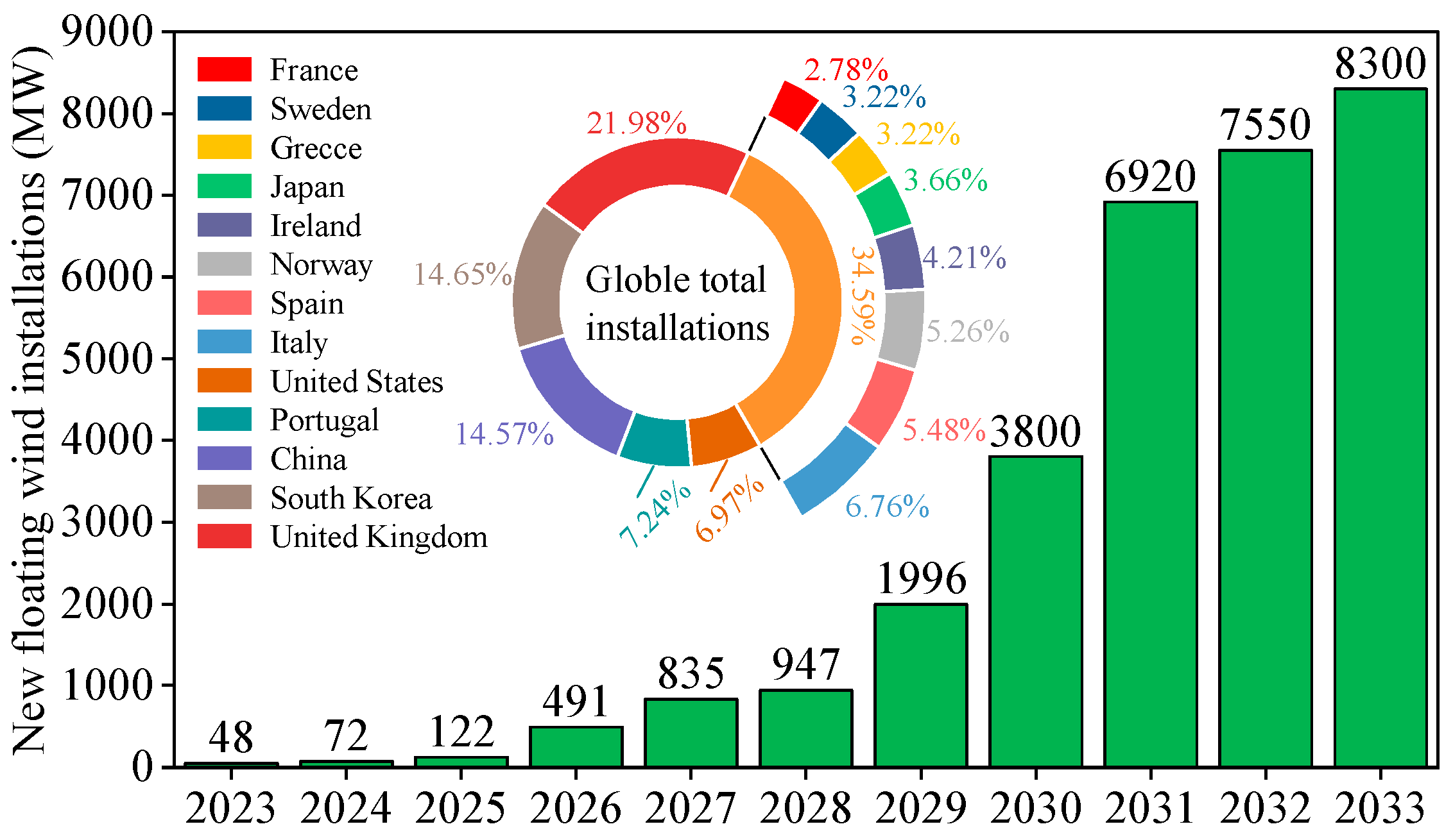
1. Introduction

2. Analysis and Calculation Theory
2.1. Wind Load
2.2. Wave Load
2.3. Frequency Domain Characteristics
2.4. Equation of Motion
3. Floating Platform Model with Heave Plate
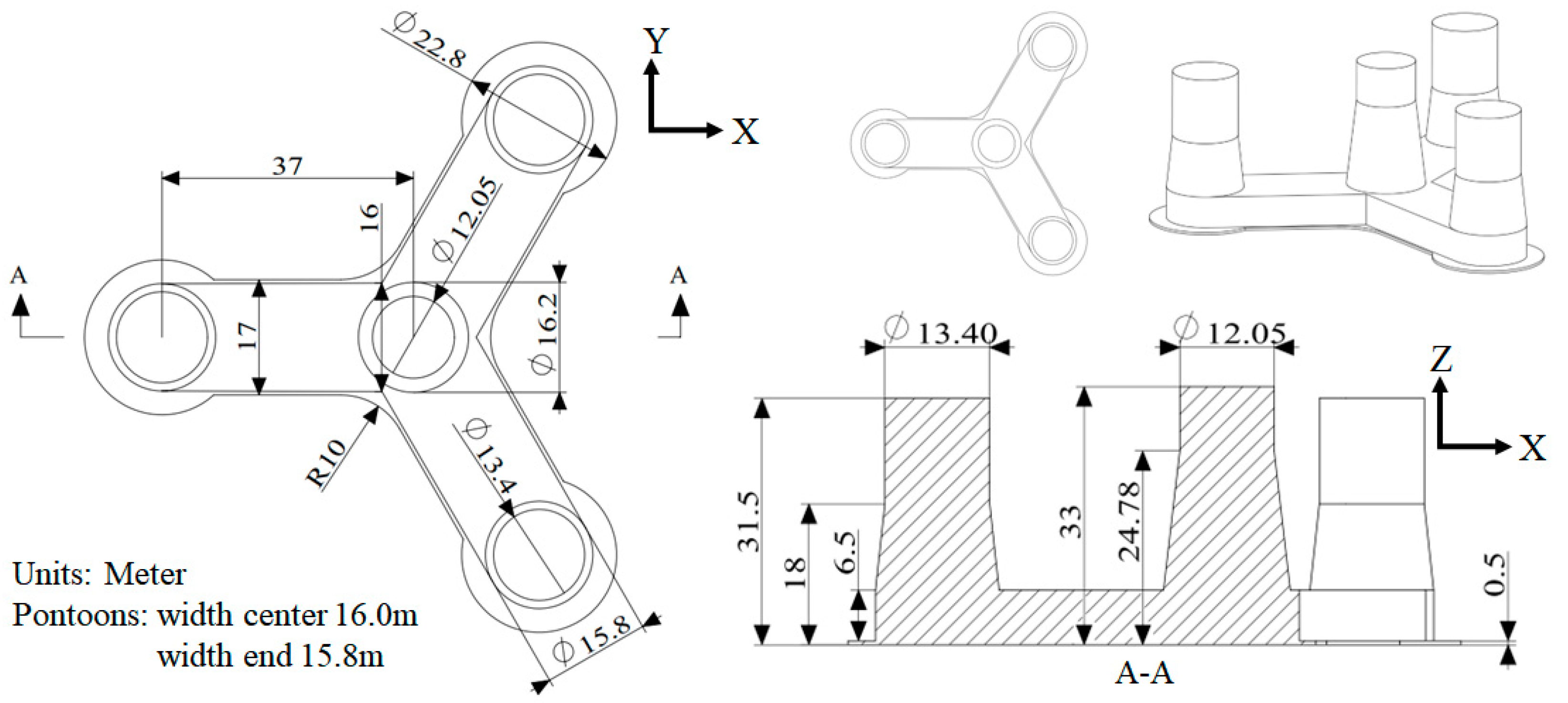
3.1. Parameters of FOWT and Simulation Verification
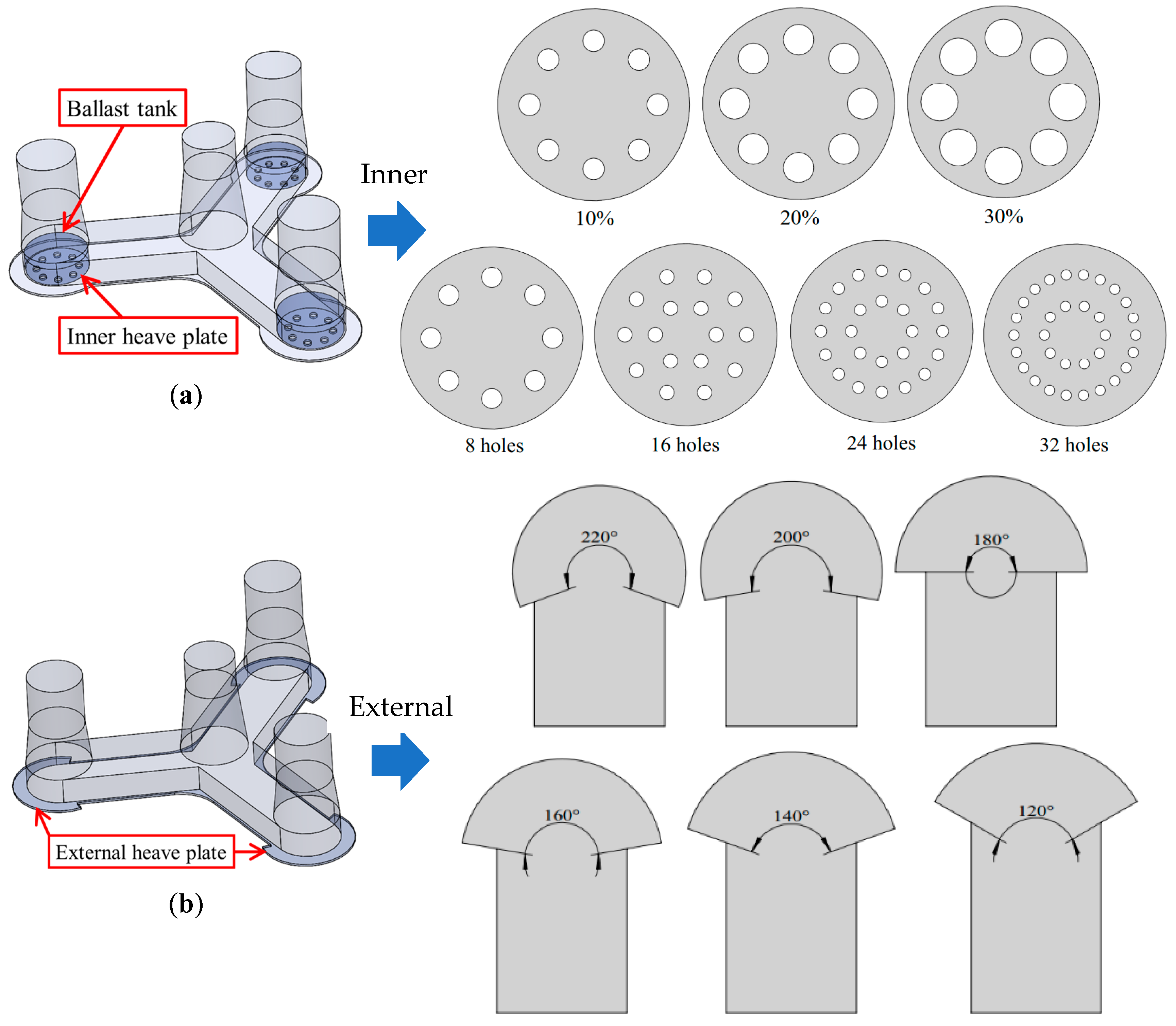
3.2. Structural Design of Heave Plate
3.3. Parameters of Environment
4. Analysis of Numerical Simulation Results
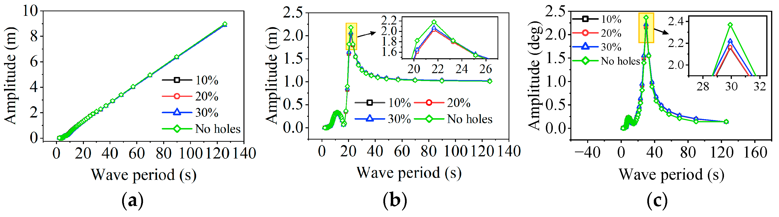
4.1. Frequency Domain Analysis
4.2. Time-Domain Analysis
5. Conclusions
Author Contributions
Funding
Institutional Review Board Statement
Informed Consent Statement
Data Availability Statement
Conflicts of Interest
References
- Fu, J.; Shi, W.; Wang, W.; Li, X.; Zhou, Y. Study on simulation of real-time hybrid model test for offshore wind turbines. Earthq. Eng. Resil. 2023, 2, 94–110. [Google Scholar] [CrossRef]
- Guo, X.; Zhang, Y.; Yan, J.; Zhou, Y.; Yan, S.; Shi, W.; Li, X. Integrated Dynamics Response Analysis for IEA 10-MW Spar Floating Offshore Wind Turbine. J. Mar. Sci. Eng. 2022, 10, 542. [Google Scholar] [CrossRef]
- Jia, W.; Liu, Q.; Lglesias, G.; Miao, W.; Yue, M.; Yang, Y.; Li, C. Investigation of barge-type FOWT in the context of concurrent and cascading failures within the mooring systems. Renew. Energy 2024, 224, 120119. [Google Scholar] [CrossRef]
- Shi, W.; Zhang, L.; Karimirad, M.; Michailides, C.; Jiang, Z.; Li, X. Combined effects of aerodynamic and second-order hydrodynamic loads for floating wind turbines at different water depths. Appl. Ocean Res. 2023, 130, 103416. [Google Scholar] [CrossRef]
- Lee, C.F.; Cheng, Z.; Ong, M.C.; Wang, K. Extreme response analysis of a floating vertical axis wind turbine based on modified environmental contour method. Ocean Eng. 2023, 270, 113459. [Google Scholar] [CrossRef]
- Han, Y.; Le, C.; Ding, H.; Cheng, Z.; Zhang, P. Stability and dynamic response analysis of a submerged tension leg platform for offshore wind turbines. Ocean Eng. 2017, 129, 68–82. [Google Scholar] [CrossRef]
- Lian, J.; Zhou, H.; Dong, X. A Theoretical Methodology and Measurement of Dynamic Characteristics of Wind Turbines with Composite Bucket Foundations. J. Mar. Sci. Eng. 2024, 12, 106. [Google Scholar] [CrossRef]
- Bhattacharya, S.; Amani, S.; Prabhakaran, A.; Macabuag, J. Hazard considerations in the vulnerability assessment of offshore wind farms in seismic zones. Earthq. Eng. Resil. 2022, 1, 88–109. [Google Scholar] [CrossRef]
- Liu, B.; Yu, J. Dynamic Response and Mooring Fracture Performance Analysis of a Semi-Submersible Floating Offshore Wind Turbine under Freak Waves. J. Mar. Sci. Eng. 2024, 12, 1414. [Google Scholar] [CrossRef]
- Shen, C.; Chen, N.-Z. A SWENSE-based wave-induced loading simulation for a semi-submersible FOWT platform. Ocean Eng. 2024, 311, 118950. [Google Scholar] [CrossRef]
- Li, J.; Liu, S.; Zhao, M.; Teng, B. Experimental investigation of the hydrodynamic characteristics of heave plates using forced oscillation. Ocean Eng. 2013, 66, 82–91. [Google Scholar] [CrossRef]
- Ye, Z.; Zhang, J.; Zhou, G.; Li, C.; Ding, Q. Research on hydrodynamic characteristics of floating wind turbine with heave plate. Acta Energiae Solaris Sin. 2019, 40, 229–236. (In Chinese) [Google Scholar]
- Li, H.; Zheng, J.; Zhang, J.; Peng, W.; Peng, J. Numerical investigation on dynamic responses of a semi-submersible wind turbine with different types of heave plates. Ocean Eng. 2024, 310, 118650. [Google Scholar] [CrossRef]
- Huang, H.; Liu, Q.; Iglesias, G.; Yue, M.; Miao, W.; Ye, Q.; Li, C.; Yang, T. A fully-coupled analysis of the spar-type floating offshore wind turbine with bionic fractal heave plate under wind-wave excitation conditions. Renew. Energy 2024, 232, 121088. [Google Scholar] [CrossRef]
- Zhang, L.; Shi, W.; Zeng, Y.; Michailides, C.; Zheng, S.; Li, Y. Experimental investigation on the hydrodynamic effects of heave plates used in floating offshore wind turbines. Ocean Eng. 2023, 267, 113103. [Google Scholar] [CrossRef]
- Yu, Z.; Amdahl, J.; Rypestøl, M.; Cheng, Z. Numerical modelling and dynamic response analysis of a 10 MW semi-submersible floating offshore wind turbine subjected to ship collision loads. Renew. Energy 2022, 184, 677–699. [Google Scholar] [CrossRef]
- Pegalajar-Jurado, A.; Bredmose, H.; Borg, M.; Straume, J.G.; Landbo, T.; Andersen, H.S.; Yu, W.; Muller, K.; Lemmer, F. State-of-the-art model for the LIFES50+OO-Star Wind Floater Semi 10MW floating wind turbine. In Proceedings of the 15th Deep Sea Offshore Wind R and D Conference (EERA DeepWind), SINTEF, Trondheim, Norway, 17–18 January 2018. [Google Scholar]
- Høeg, C.E.; Zhang, Z. A semi-analytical hydrodynamic model for floating offshore wind turbines (FOWT) with application to a FOWT heave plate tuned mass damper. Ocean Eng. 2023, 287, 115756. [Google Scholar] [CrossRef]
- Medina-Manuel, A.; Botia-Vera, E.; Saettone, S.; Calderon-Sanchez, J.; Bulian, G.; Souto-Iglesias, A. Hydrodynamic coefficients from forced and decay heave motion tests of a scaled model of a column of a floating wind turbine equipped with a heave plate. Ocean Eng. 2022, 252, 110985. [Google Scholar] [CrossRef]
- Wang, B.; Xu, Z.; Li, C.; Wang, D.; Ding, Q. Hydrodynamic characteristics of forced oscillation of heave plate with fractal characteristics based on floating wind turbine platform. Ocean Eng. 2020, 212, 107621. [Google Scholar] [CrossRef]
- Yue, M.; Liu, Q.; Li, C.; Ding, Q.; Cheng, S.; Zhu, H. Effects of heave plate on dynamic response of floating wind turbine Spar platform under the coupling effect of wind and wave. Ocean Eng. 2020, 201, 107103. [Google Scholar] [CrossRef]
- GWEC. Global Offshore Wind Report 2024; Global Wind Energy Council: Brussels, Belgium, 2024; pp. 142–145. [Google Scholar]
- ISO 19902:2020 Petroleum and Natural Gas Industries—Fixed Steel Offshore Structures. Available online: https://www.iso.org/standard/65688.html/ (accessed on 18 May 2024).
- Gong, D.; Zhou, J.; Liu, X.; Li, F. Modeling and vortex-induced vibrations of semi-submersible floating offshore wind turbines. Mech. Syst. Signal Process. 2024, 220, 111667. [Google Scholar] [CrossRef]
- Wang, J.; Ren, Y.; Shi, W.; Collu, M.; Venugopal, V.; Li, X. Multi-objective optimization design for a 15 MW semisubmersible floating offshore wind turbine using evolutionary algorithm. Appl. Energy 2025, 377, 124533. [Google Scholar] [CrossRef]
- Li, Y.; Li, H.; Wang, B.; Meng, H.; Su, O.; Tang, Y. Effects of various freak waves on dynamic responses of a Spar-buoy floating offshore wind turbine. Ocean Eng. 2024, 311, 118837. [Google Scholar] [CrossRef]
- Li, J.; Zuo, H.; Zuo, J.; Jiang, Y.; Liu, S. Study on the mooring systems attaching clump weights and heavy chains for improving the typhoon resistance of floating offshore wind turbines. Ocean Eng. 2024, 311, 118734. [Google Scholar] [CrossRef]
- Yang, Y.; Shi, Z.; Fu, J.; Ma, L.; Yu, J.; Fang, F.; Li, C.; Chen, S.; Yang, W. Effects of tidal turbine number on the performance of a 10 MW-class semi-submersible integrated floating wind-current system. Energy 2023, 285, 128789. [Google Scholar] [CrossRef]
- Chen, H.; Gilbert, R.P.; Guyenne, P. Dispersion and attenuation in a porous viscoelastic model for gravity waves on an ice-covered ocean. Eur. J. Mech. B/Fluids 2019, 78, 88–105. [Google Scholar] [CrossRef]
- Luo, T.; Tian, D.; Wang, R.; Liao, C. Stochastic Dynamic Response Analysis of a 10 MW Tension Leg Platform Floating Horizontal Axis Wind Turbine. Energies 2018, 11, 3341. [Google Scholar] [CrossRef]
- Horcas, S.G.; Debrabandere, F.; Tartinville, B.; Hirsch, C.; Coussement, G. Extension of the Non-Linear Harmonic method for the study of the dynamic aeroelasticity of horizontal axis wind turbines. J. Fluids Struct. 2017, 73, 100–124. [Google Scholar] [CrossRef]


| Property | Parameter |
|---|---|
| Total platform mass [kg] | 2.17 × 10⁷ |
| Centroid position (x,y,z) [m] | (0, 0, −15.23) |
| Center of buoyancy position (x,y,z) [m] | (0, 0, −14.24) |
| Moment of inertia of roll Ixx [kg·m2] | 9.43 × 10⁹ |
| Moment of inertia of pitch Iyy [kg·m2] | 9.43 × 10⁹ |
| Moment of inertia of yaw Izz [kg·m2] | 1.63 × 10¹⁰ |
| Drainage volume [m3] | 2.35 × 10⁴ |
| Draught [m] | 22 |
| Number of lines | 3 |
| Pre-tension [N] | 1.67 × 10⁶ |
| Equivalent mass per length in air [kg/m] | 375.38 |
| Equivalent weight per length in water [N/m] | 3200.6 |
| Extensional stiffness EA [N] | 1.506 × 10⁹ |
| Physical chain diameter [m] | 0.137 |
| Parameter | FAST | Sesam | Deviation |
|---|---|---|---|
| Heave | 20.92 | 21.67 | 3.56% |
| Pitch | 31.65 | 29.92 | 5.45% |
| Condition | Effective Wave Height [m] | Peak Period [s] | Wind Speed [m/s] |
|---|---|---|---|
| EC1 | 2.34 | 9.56 | 7 |
| EC2 | 3.3 | 9.71 | 8.5 |
| EC3 | 4.14 | 10.04 | 11.4 |
| EC4 | 5.16 | 10.29 | 14.7 |
| EC5 | 6.18 | 10.51 | 17.8 |
| EC6 | 6.99 | 11.12 | 21.3 |
| EC 1 | Number of Holes | 8 Holes | 16 Holes | ||||
|---|---|---|---|---|---|---|---|
| DOF 2 | Surge [m] | Heave [m] | Pitch [deg] | Surge [m] | Heave [m] | Pitch [deg] | |
| EC1 | MV 3 | 0.115 | −0.017 | 0.343 | 0.115 | −0.017 | 0.343 |
| SD 4 | 0.397 | 0.138 | 0.361 | 0.397 | 0.138 | 0.365 | |
| AMP 5 | 2.270 | 1.174 | 2.087 | 2.267 | 1.177 | 2.085 | |
| EC2 | MV | 0.072 | −0.021 | 0.479 | 0.073 | −0.021 | 0.479 |
| SD | 1.166 | 0.194 | 0.841 | 1.163 | 0.194 | 0.836 | |
| AMP | 6.399 | 1.587 | 4.295 | 6.246 | 1.598 | 4.213 | |
| EC3 | MV | 0.182 | −0.021 | 0.789 | 0.174 | −0.022 | 0.788 |
| SD | 1.198 | 0.260 | 1.038 | 1.238 | 0.260 | 1.050 | |
| AMP | 6.850 | 1.995 | 5.417 | 7.061 | 1.979 | 5.590 | |
| EC4 | MV | 0.057 | −0.023 | 0.499 | 0.052 | −0.023 | 0.498 |
| SD | 1.434 | 0.359 | 1.469 | 1.460 | 0.358 | 1.458 | |
| AMP | 8.658 | 2.723 | 9.333 | 8.697 | 2.714 | 9.157 | |
| EC5 | MV | −0.062 | −0.026 | 0.459 | −0.020 | −0.026 | 0.460 |
| SD | 1.790 | 0.711 | 2.798 | 1.720 | 0.695 | 2.665 | |
| AMP | 11.440 | 5.336 | 14.894 | 10.379 | 5.171 | 13.553 | |
| EC6 | MV | −0.068 | −0.030 | 0.412 | −0.005 | −0.036 | 0.402 |
| SD | 2.040 | 0.593 | 2.570 | 2.163 | 0.565 | 2.466 | |
| AMP | 11.024 | 4.769 | 13.111 | 11.272 | 4.786 | 13.553 | |
| EC | Angle | 120-Degree | 140-Degree | 220-Degree | ||||||
|---|---|---|---|---|---|---|---|---|---|---|
| DOF | Surge [m] | Heave [m] | Pitch [deg] | Surge [m] | Heave [m] | Pitch [deg] | Surge [m] | Heave [m] | Pitch [deg] | |
| EC1 | MV | 0.123 | −0.017 | 0.411 | 0.129 | −0.017 | 0.409 | 0.132 | −0.017 | 0.404 |
| SD | 0.417 | 0.128 | 0.722 | 0.445 | 0.129 | 0.579 | 0.373 | 0.140 | 0.534 | |
| AMP | 2.493 | 0.989 | 3.580 | 2.595 | 0.961 | 2.659 | 2.262 | 1.037 | 2.391 | |
| EC2 | MV | 0.210 | −0.017 | 0.576 | 0.194 | −0.018 | 0.575 | 0.185 | −0.018 | 0.571 |
| SD | 0.490 | 0.190 | 0.551 | 0.548 | 0.194 | 0.831 | 0.621 | 0.199 | 0.838 | |
| AMP | 2.851 | 1.539 | 3.257 | 3.231 | 1.487 | 4.713 | 3.540 | 1.632 | 4.006 | |
| EC3 | MV | 0.238 | −0.021 | 0.948 | 0.248 | −0.019 | 0.952 | 0.265 | −0.020 | 0.943 |
| SD | 1.104 | 0.278 | 1.422 | 0.889 | 0.264 | 1.666 | 0.950 | 0.261 | 1.375 | |
| AMP | 6.801 | 2.042 | 6.776 | 5.413 | 2.244 | 7.173 | 5.910 | 2.098 | 6.598 | |
| EC4 | MV | 0.090 | −0.025 | 0.600 | 0.076 | −0.020 | 0.621 | 0.113 | −0.022 | 0.592 |
| SD | 1.485 | 0.337 | 2.303 | 1.197 | 0.332 | 2.084 | 1.380 | 0.382 | 1.276 | |
| AMP | 8.939 | 2.721 | 12.846 | 7.579 | 2.836 | 10.383 | 6.999 | 3.068 | 6.509 | |
| EC5 | MV | 0.054 | −0.029 | 0.521 | 0.034 | −0.025 | 0.533 | −0.169 | −0.041 | 0.493 |
| SD | 1.835 | 0.494 | 2.724 | 1.642 | 0.423 | 1.812 | 2.654 | 0.578 | 3.222 | |
| AMP | 12.832 | 3.534 | 17.144 | 8.609 | 3.097 | 9.019 | 14.803 | 4.326 | 18.523 | |
| EC6 | MV | −0.114 | −0.044 | 0.491 | −0.067 | −0.035 | 0.480 | −0.179 | −0.048 | 0.444 |
| SD | 2.489 | 0.663 | 3.769 | 2.246 | 0.667 | 2.769 | 2.819 | 0.668 | 3.478 | |
| AMP | 13.614 | 4.392 | 19.233 | 13.171 | 4.480 | 16.083 | 15.652 | 4.079 | 19.285 | |
Disclaimer/Publisher’s Note: The statements, opinions and data contained in all publications are solely those of the individual author(s) and contributor(s) and not of MDPI and/or the editor(s). MDPI and/or the editor(s) disclaim responsibility for any injury to people or property resulting from any ideas, methods, instructions or products referred to in the content. |
© 2024 by the authors. Licensee MDPI, Basel, Switzerland. This article is an open access article distributed under the terms and conditions of the Creative Commons Attribution (CC BY) license (https://creativecommons.org/licenses/by/4.0/).
Share and Cite
Wang, H.; Yang, Y.; Guo, Y.; Lian, J. Influence of Heave Plate on the Dynamic Response of a 10 MW Semisubmersible Floating Platform. J. Mar. Sci. Eng. 2024, 12, 2156. https://doi.org/10.3390/jmse12122156
Wang H, Yang Y, Guo Y, Lian J. Influence of Heave Plate on the Dynamic Response of a 10 MW Semisubmersible Floating Platform. Journal of Marine Science and Engineering. 2024; 12(12):2156. https://doi.org/10.3390/jmse12122156
Chicago/Turabian StyleWang, Haijun, Yuhang Yang, Yaohua Guo, and Jijian Lian. 2024. "Influence of Heave Plate on the Dynamic Response of a 10 MW Semisubmersible Floating Platform" Journal of Marine Science and Engineering 12, no. 12: 2156. https://doi.org/10.3390/jmse12122156
APA StyleWang, H., Yang, Y., Guo, Y., & Lian, J. (2024). Influence of Heave Plate on the Dynamic Response of a 10 MW Semisubmersible Floating Platform. Journal of Marine Science and Engineering, 12(12), 2156. https://doi.org/10.3390/jmse12122156