Article

Concentric Compressive Behavior and Design of Stainless Steel–Concrete Double-Skin Composite Tubes Influenced by Dual Hydraulic Pressures

1
School of Civil Engineering, Xi’an University of Architecture and Technology, Xi’an 710055, China
2
Key Lab of Structural Engineering and Earthquake Resistance, Ministry of Education (XAUAT), Xi’an 710055, China
3
Zhongmin Mingtai Group Co., Ltd., Xiamen 361000, China
*
Author to whom correspondence should be addressed.
J. Mar. Sci. Eng. 2024, 12(12), 2140; https://doi.org/10.3390/jmse12122140
Submission received: 26 September 2024 / Revised: 30 October 2024 / Accepted: 20 November 2024 / Published: 23 November 2024
(This article belongs to the Special Issue Analysis and Design of Marine Structures)

Abstract

:
The external hydraulic pressure and internal medium pressure acting on submarine pipelines can lead to the coupling effect of active and passive constraints on the mechanical performance of steel–concrete double-skin composite tubes, resulting in a significantly different bearing capacity mechanism compared to terrestrial engineering. In this paper, the full-range concentric compressive mechanism of new-type stainless steel–concrete double-skin (SSCDS) composite tubes subjected to dual hydraulic pressure was analyzed by the finite element method. The influence of geometric–physical parameters at various water depths was discussed. The key results reveal that imposing dual hydraulic pressures significantly improves the confinement of double-skin tubes to encased concrete, resulting in a higher axial compressive strength and a non-uniform stress distribution; increasing the material strengths of concrete, outer tubes and inner tubes results in an approximately linear enhancement in axial bearing capacity; enhancing the diameter-to-thickness ratios of outer tubes and inner tubes can decrease the bearing capacity of SSCDS composite tubes; and the axial compression strength of SSCDS composite tubes with a higher hollow ratio of 0.849 tends to decrease with increasing outer hydraulic pressure. A practical method that integrates the effects of dual hydraulic pressures was developed and validated for the strength calculation of SSCDS composite tubes. This research provides fundamental guidelines for the application of pipe-in-pipe structures in deep-sea engineering.

1. Introduction

In recent years, pipe-in-pipe (PIP) structures, especially concrete-filled double-skin steel tubes, have been gradually applied in engineering projects such as jacket platforms, wind turbine towers, and submarine pipelines due to their excellent performance [1,2]. In the marine corrosion environment, the application of stainless steel in PIP structures shows broad prospects, promoting the development of new-type stainless steel–concrete double-skin composite tubes that are composed of an outer stainless steel tube, sandwich concrete, and an inner carbon steel tube [3,4]. Compared to traditional steel pipes, stainless steel–concrete double-skin (SSCDS) composite tubes demonstrate higher bearing capacity and longer service lives in deep-sea engineering, such as in submarine oil and gas pipelines, due to the composite action of double-skin tubes and sandwich concrete. The adoption of stainless steel in SSCDS structures provides a more durable and reliable structural form choice for applications in the marine engineering industry. Additionally, stainless steel exhibits high long-term durability and low maintenance costs under extreme environmental conditions, such as high temperature and high humidity. The recyclability and environmental friendliness of stainless steel also offer broad prospects for its application in green infrastructure. Research on the basic mechanical performance of SSCDS composite tubes can accelerate their application in ocean engineering [5,6,7].
Many scholars have examined the axial compression, anti-bending, and torsional behaviors of traditional carbon steel–concrete–carbon steel double-skin composite tubes [8,9,10,11,12,13,14,15,16,17,18,19,20]. To improve corrosion resistance, the mechanical behavior of SSCDS composite tubes under concentric compressive loading is progressively being investigated [21,22,23,24,25]. For example, Han et al. [21] tested the axial compression behavior of stainless steel–concrete–carbon steel double-skin tubular columns, and a practical design method was proposed. An investigation by Wang et al. [22] revealed inconsistencies in the reliability of contemporary design standards; specifically, EC4 and AS 5100 tend to yield non-conservative estimations, whereas AISC 360 and ACI 318 produce results that are both erratic and excessively conservative. The study results of Zhou et al. [25] point out that the ACI code predicts a conservative result due to the neglect of the confinement effect, and EC4 is generally accurate. The aforementioned studies on traditional carbon steel–concrete double-skin composite tubes and SSCDS composite tubes primarily focus on land engineering with passive confinement, and the corresponding design methods significantly deviate from the predicted results. Existing design methods may not be suitable for predicting the load-bearing capacity of SSCDS composite tubes under deep-sea pressure, and there remains considerable uncertainty that requires further research.
The research on carbon steel–concrete–stainless steel double-skin tubular tubes by Wang and Han [26] has revealed that the confining interaction between double-skin tubes and encased concrete is significantly influenced by external hydraulic pressure and the internal pressure of the oil and gas media. Wang et al. [27] analyzed the concentric compression behavior of stainless steel–concrete–carbon steel double-skin stub tubes under outer hydraulic pressure, demonstrating that composite action and load-bearing capacity are enhanced due to high outer pressure, and the design method of T/CCES 7-2020 predicts a declining tendency with increasing water depth. It can be seen that the high pressure in the deep sea indeed has a significant impact on the constraint effect of steel–concrete composite structures. For stainless steel–concrete double-skin (SSCDS) composite tubes used in deep-sea oil and gas pipelines, the dual pressures of outer hydrostatic pressure and the inner medium pressure of the service stage will affect the service performance by influencing the confinement action and stress distribution. Appropriate and necessary investigations into mechanical mechanisms, the effects of key parameters, and design methods are urgently needed for SSCDS composite tubes subjected to dual hydraulic pressure in order to promote their potential application in deep-sea oil and gas pipelines.
This paper analyzed the concentric compressive behavior of SSCDS composite tubes via the finite element (FE) method in the ABAQUS program, revealing the full-range composite mechanism and effects of key parameters under the service condition of dual hydraulic pressure. Subsequently, a corresponding calculation method incorporating the effect of dual hydraulic pressure was established for application in deep-water structures. The results of this research can offer critical design insights for the development of marine engineering projects.

2. Finite Element Simulation

2.1. FE Model

As shown in Figure 1, a simplified secondary flow relationship was used to simulate the performance of the inner carbon steel tube [28]; the Rasmussen model was adopted to model the behavior of the outer stainless steel tube [29]. The equations for carbon steel and stainless steel are respectively offered in Equation (1) and Equations (2)–(8).
σ s = E s ε s ε s ε y f y ε y ε s k 1 ε y k 3 f y + E s 1 k 3 ε y k 2 k 1 2 ε s k 2 ε y 2    k 1 ε y ε s k 2 ε y f u ε s k 2 ε y
where the values of k1 and k2 can be set as 4.5 and 45, respectively; the value of k3 is 1.4, while the yield strength falls within the range of 235 MPa to 355 MPa; otherwise, the value of k3 is 1.2; fy is the yield strength; fu is the ultimate strength; Es is the elasticity modulus of carbon steel.
ε s = σ s E 0 + 0.002 σ s σ 0.2 n           σ s σ 0.2 σ s σ 0.2 E 0.2 + ε ssu σ s σ 0.2 σ ssu σ 0.2 m + ε 0.2    σ s > σ 0.2
E 0.2 = E 0 1 + 0.002 n / e
e = σ 0.2 E 0 ;   n = ln ( 20 ) ln ( σ 0.2 / σ 0.01 )
m = 1 + 3.5 σ 0.2 σ ssu
σ ssu = σ 0.2 1 0.0375 ( n 5 ) 0.2 + 185 e
ε ssu = 1 σ 0.2 σ ssu
ε 0.2 = σ 0.2 E 0 + 0.002
where σ0.2 is the 0.2% proof stress for stainless steel; σssu is the tensile strength; εssu is the ultimate strain at σssu; ε0.2 is the strain at σ0.2; E0 is the elasticity modulus of stainless steel. Moreover, Han’s confined concrete model under axial compression conditions was employed to evaluate the response of concrete infill [30]. The tensile performance of sandwich concrete was simulated by the fracture mechanics approach,
f t 0 = 0.26 × ( 1.25 f c ) 2 / 3
G F = 73 ( f c ) 0.18
where fc is the compressive strength of concrete cylinder; ft0 is the tensile strength; GF is the fracture energy.
The S4R shell element was adopted to simulate the outer stainless steel tube and inner carbon steel tube, and the C3D8R solid element was employed to model the encased concrete. The interactions in the normal and tangential directions at the steel–concrete interfaces were determined utilizing the rigid contact model and Coulomb friction theory, with the friction coefficient at 0.6. The simulation procedure was divided into three steps (Figure 2) to research the compressive performance of SSCDS composite tubes: the SSCDS composite tube was first in its initial state with the fixed boundary; then, the outer hydraulic pressure and inner medium pressure were respectively inserted into the outer stainless steel tube and inner carbon steel tube; subsequently, the compression load was concentrically loaded onto the coupling reference point by a displacement-controlling method. The upper end of the FE model was only allowed to generate axial deformation. The general static analysis in the ABAQUS program was used to obtain the responses of SSCDS composite tubes, where the geometric nonlinearity and material nonlinearity were fully considered.

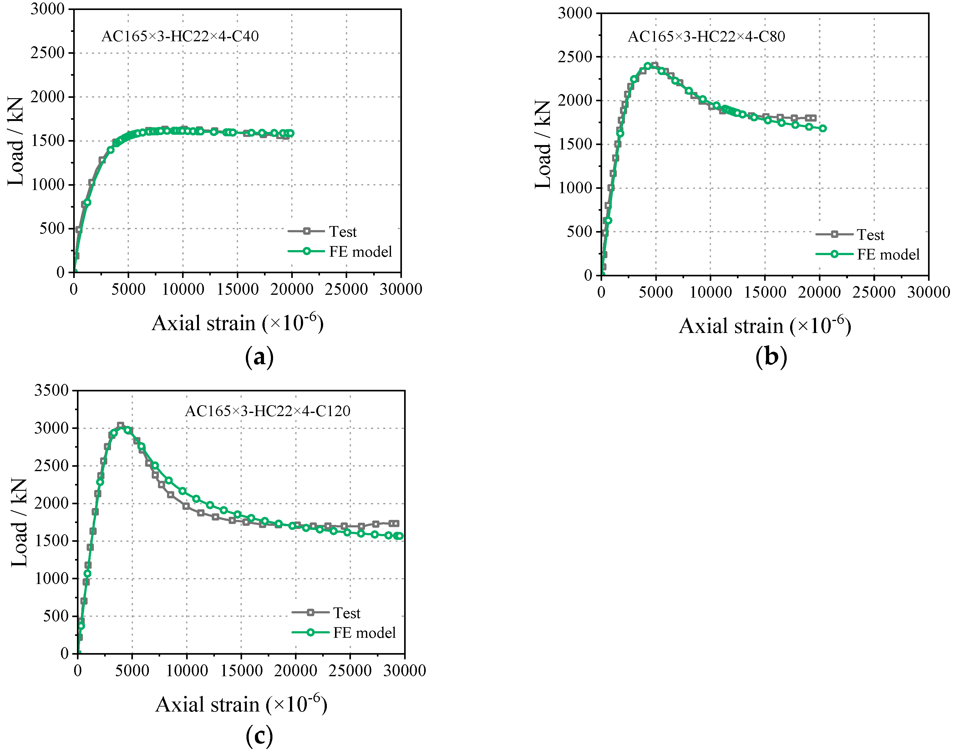
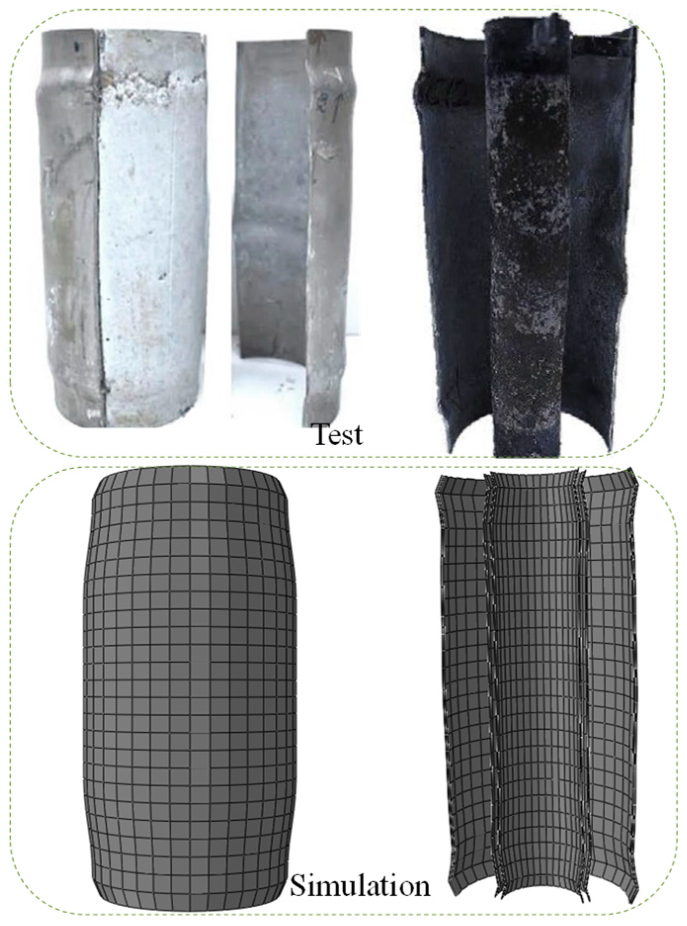
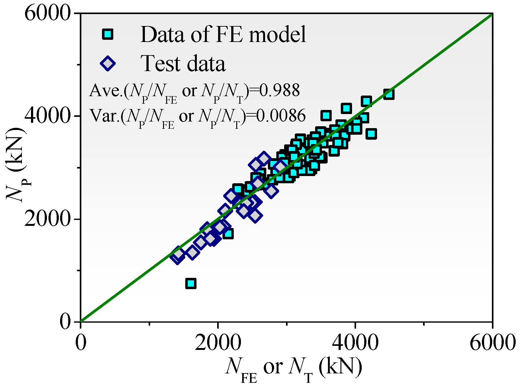
2.2. Validation of FE Model

The formed FE model was compared to the collected test results of reference [22] for verification. The simulated bearing capacities are shown in Table 1, where Do and Di are the diameters of the outer tube and inner tube; to and ti are the wall thicknesses of the outer tube and inner tube; fc indicates the strength of the concrete cylinder; and fyo indicates the yield strength of the outer stainless steel tube; fyi is the yield strength of the inner tube; NT is the tested strengths of SSCDS composite tubes; NFE is the numerical strengths of SSCDS composite tubes. It can be observed that the numerical capacity NFE behaves similarly to the test capacity NT by achieving the mean value (NFE/NT) of 0.9938. Typical responses of load versus displacement were offered to validate the accuracy of the FE model in Figure 3, in which the simulated curves predict well as regards the initial elastic behavior, post-peak degradation, and its peak strength. The predicted failure mode of the FE model effectively captures the local buckling of outer or inner tubes compared to the test phenomenon (Figure 4). It can be concluded that the FE model established in this paper has good predictive modeling accuracy, which can provide references for subsequent mechanism analysis and parameter analysis.

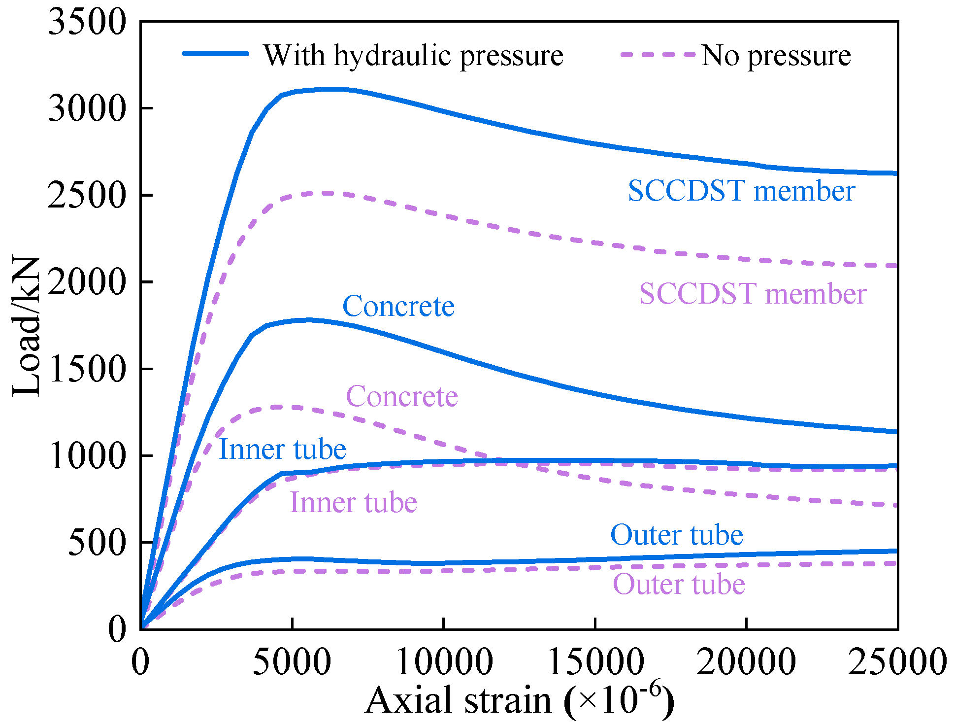
3. Full-Range Analysis of Compressive Performance

This section aims to reveal the full-range compressive response of SSCDS composite tubes influenced by dual hydraulic pressures. The typical specimen analyzed by the validated FE model was used to give an example for explanation. The detailed information for the typical specimen is as follows: the outer stainless steel tube’s diameter Do is 165 mm; the wall thickness of the outer tube to is 3 mm; the inner carbon steel tube’s diameter Di is 90 mm; the wall thickness of the inner tube ti is 4 mm; the yield strength of the outer tube fyo is 280 MPa, and the yield strength of the inner tube fyi is 960 MPa; the length of the specimen is 413 mm; the compressive strength of concrete cylinder is 80 MPa; the hydraulic pressure on outer tube surface at a water depth of 1000 m is 10 MPa, and the inner medium pressure of oil and gas is also set as 10 MPa. The influence of dual hydraulic pressures on its compressive performance is analyzed in Figure 5, Figure 6 and Figure 7.
As shown in Figure 5, the specimen subjected to dual hydraulic pressure shows an excellent performance in terms of the peak load and post-peak behavior, compared to the specimen without pressures, in which the axial compressive strength under dual hydraulic pressures is increased by 23.85% versus its benchmark without pressure. The strength contributions of outer or inner tubes and encased concrete are demonstrated in Figure 5, analyzing the origin of the strength increment, where it can be observed that the contributions of the inner carbon steel tube and outer stainless steel tube behave similarly to the axial compressive strength whether the SSCDS composite tubes are exposed to dual hydraulic pressures or not. However, the axial responses of sandwich concrete are totally different. The dual hydraulic pressures place the sandwich concrete into a higher confinement state, therefore resulting in a higher axial compressive strength compared to its benchmark. The normal interfacial pressures in Figure 6 can account for this. The initial dual hydraulic pressures produce the active confinement action of double-skin tubes on sandwich concrete, thereby leading to an obvious increase in interfacial pressures. It also can be observed that the confinement effect without hydraulic pressures mainly derives from the interaction between the outer stainless steel pipe and sandwich concrete, as displayed in Figure 6a; in that case, the confinement contribution of the inner tube to concrete is nearly low. In fact, this phenomenon causes the stress of the sandwich concrete to be unevenly distributed along the radial direction, and to be in a state of non-uniform constraint (Figure 7). The presence of dual hydrostatic pressures leads to a more pronounced difference in the stress distribution of concrete.

4. Parametric Study

This section presents the outcomes of the parametric analysis at various water depths, which encompasses the effects of the outer stainless steel tube’s diameter-to-thickness ratio, the inner carbon steel tube’s diameter-to-thickness ratio, material strengths, and hollow ratios, as shown in Table 2. The reference specimen aligns with the specimen delineated in Section 3. The results are discussed below.

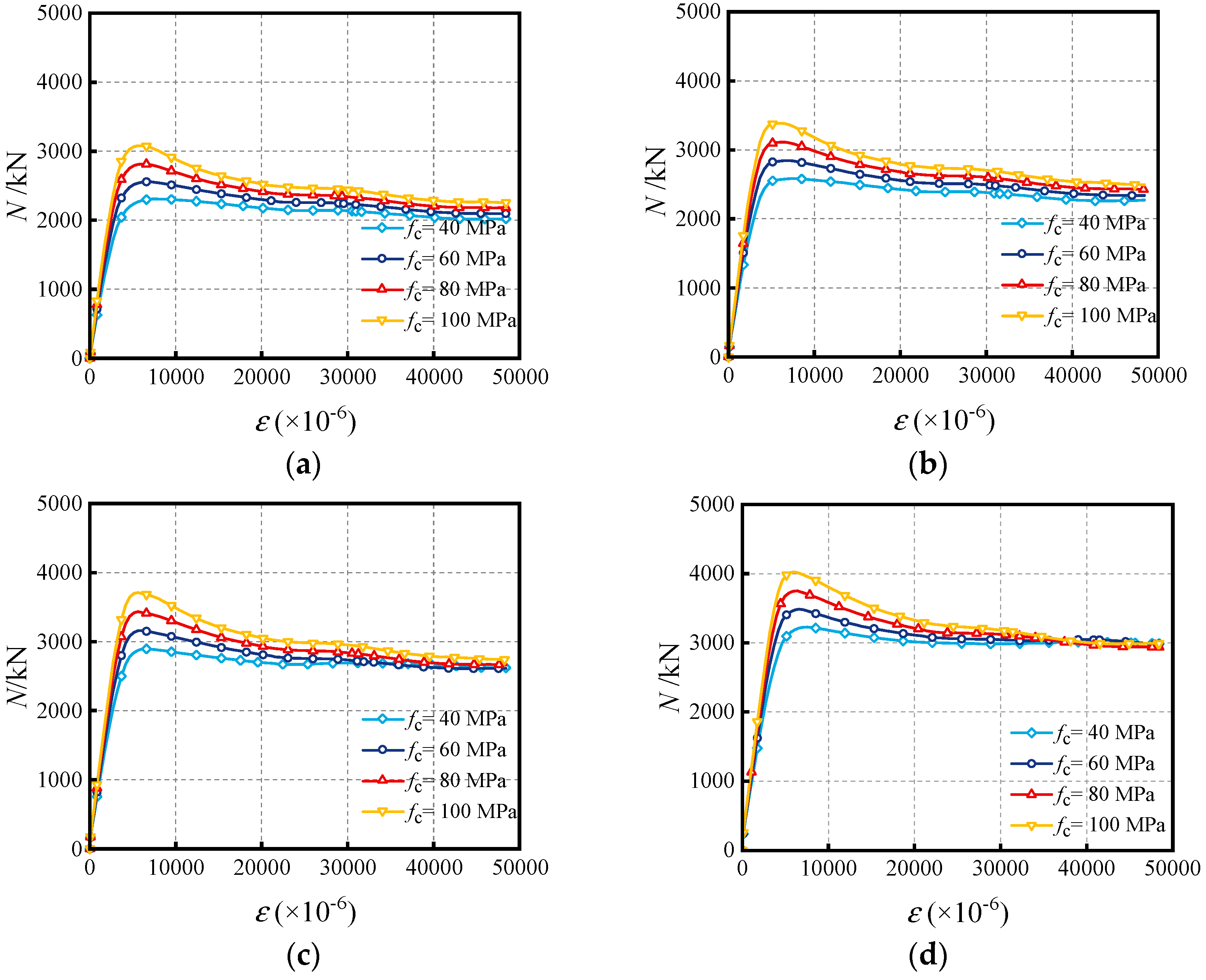
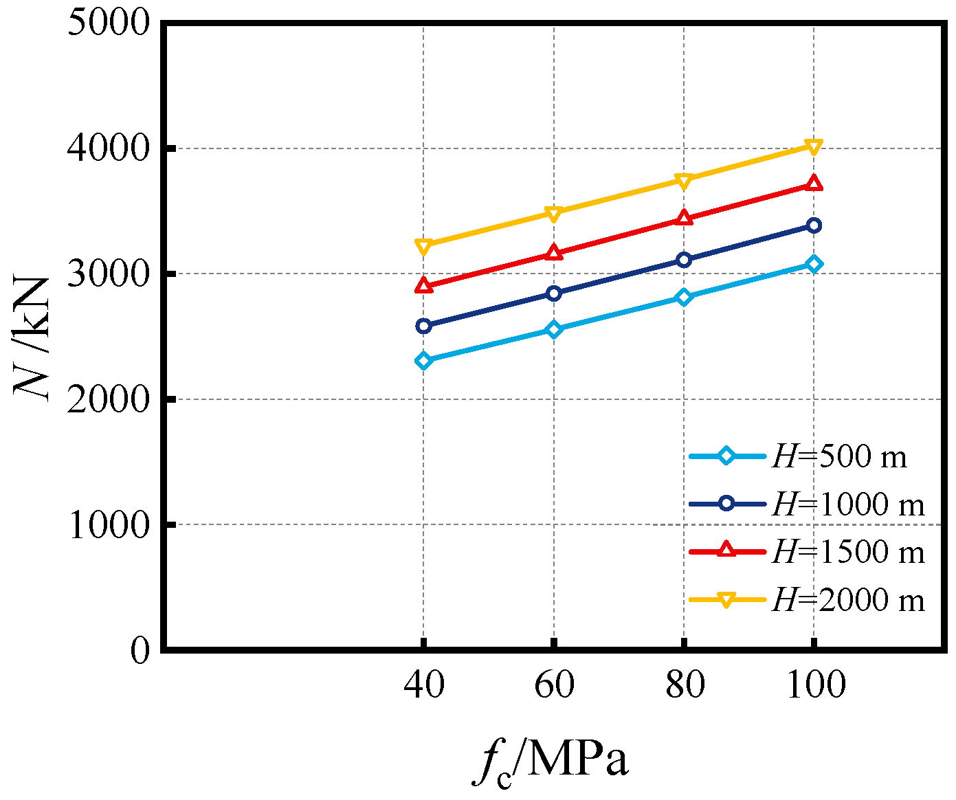
4.1. Influence of Compressive Concrete Strength (fc)

Figure 8 displays the influence of compressive concrete strength at various water depths (namely, the outer hydraulic pressure). Generally, the axial bearing capacity is increased while improving the concrete strength. As shown in Figure 9, increasing concrete strength leads to linear enhancement in the bearing capacity, e.g., at a water depth (H) of 1000 m, the axial bearing capacity is gradually improved by 10.11%, 20.44%, and 31.07%, improving the fc from 40 MPa to 60 MPa, 80 MPa and 100 MPa. While keeping the inner medium pressure constant, increasing the outer hydraulic pressure can improve the bearing capacity, e.g., for the SSCDS composite tube with fc = 60 MPa, its axial strength is enhanced by 11.29%, 23.58%, and 36.45% with the deepening of water depth from 500 m to 1000 m, 1500 m, and 2000 m, respectively.

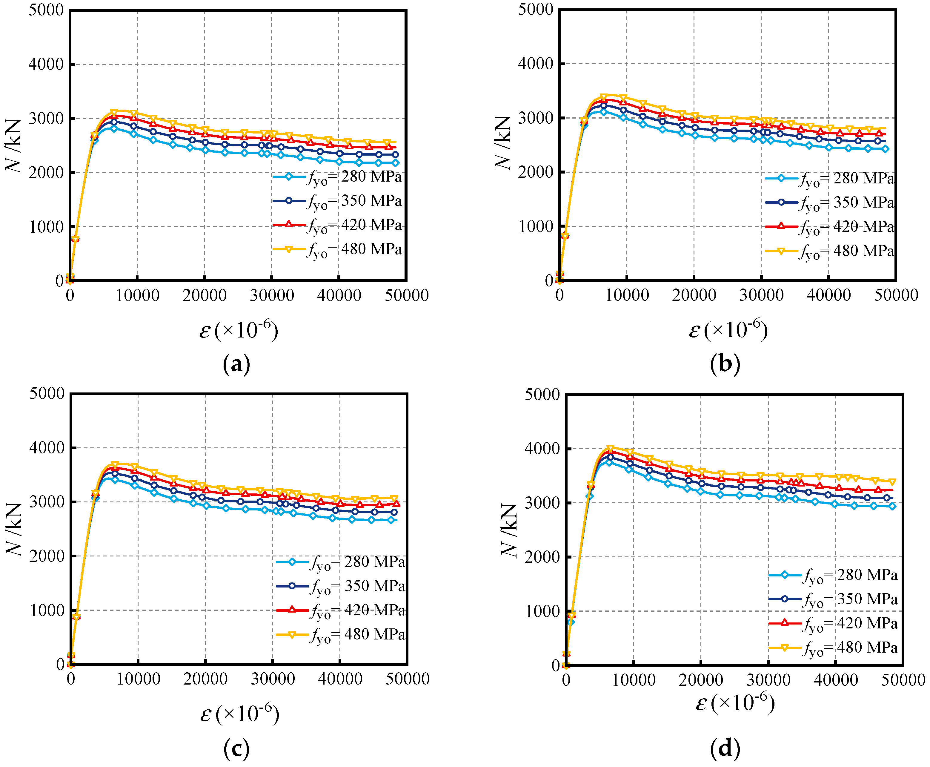
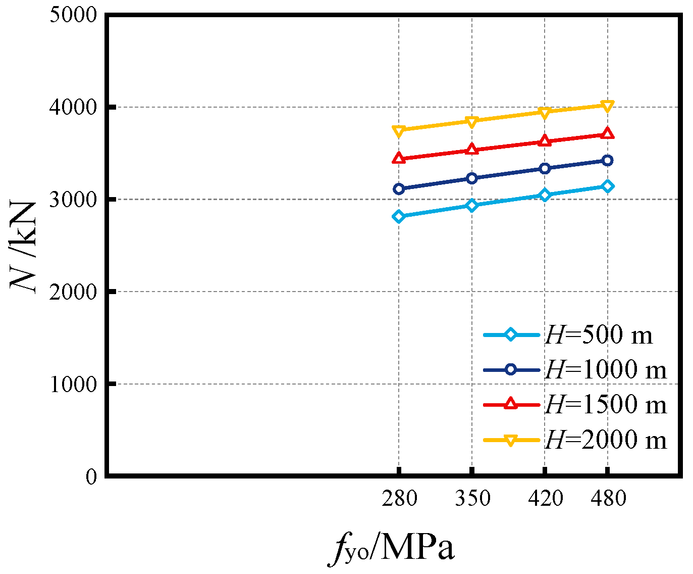
4.2. Influence of Yield Strength of Outer Tube (fyo)

Figure 10 and Figure 11 display the influence of the yield strength of the outer tube. It can be observed that increasing strength fyo approximately produces a linear enhancement in bearing capacity. For example, at a water depth of H = 1000 m, improving the strength fyo from 280 MPa to 350 MPa, 420 MPa, and 480 MPa, respectively, enhances the axial capacity by 3.69%, 7.12% and 9.99%. On the other hand, deepening the water depth at a specific yield strength fyo also improves the bearing capacity of SSCDS composite tubes, e.g., for the SSCDS composite tubes having fyo = 350 MPa, deepening the water depth from 500 m to 1000 m increases the bearing capacity by 10.00%, 20.42% and 31.20%, respectively.

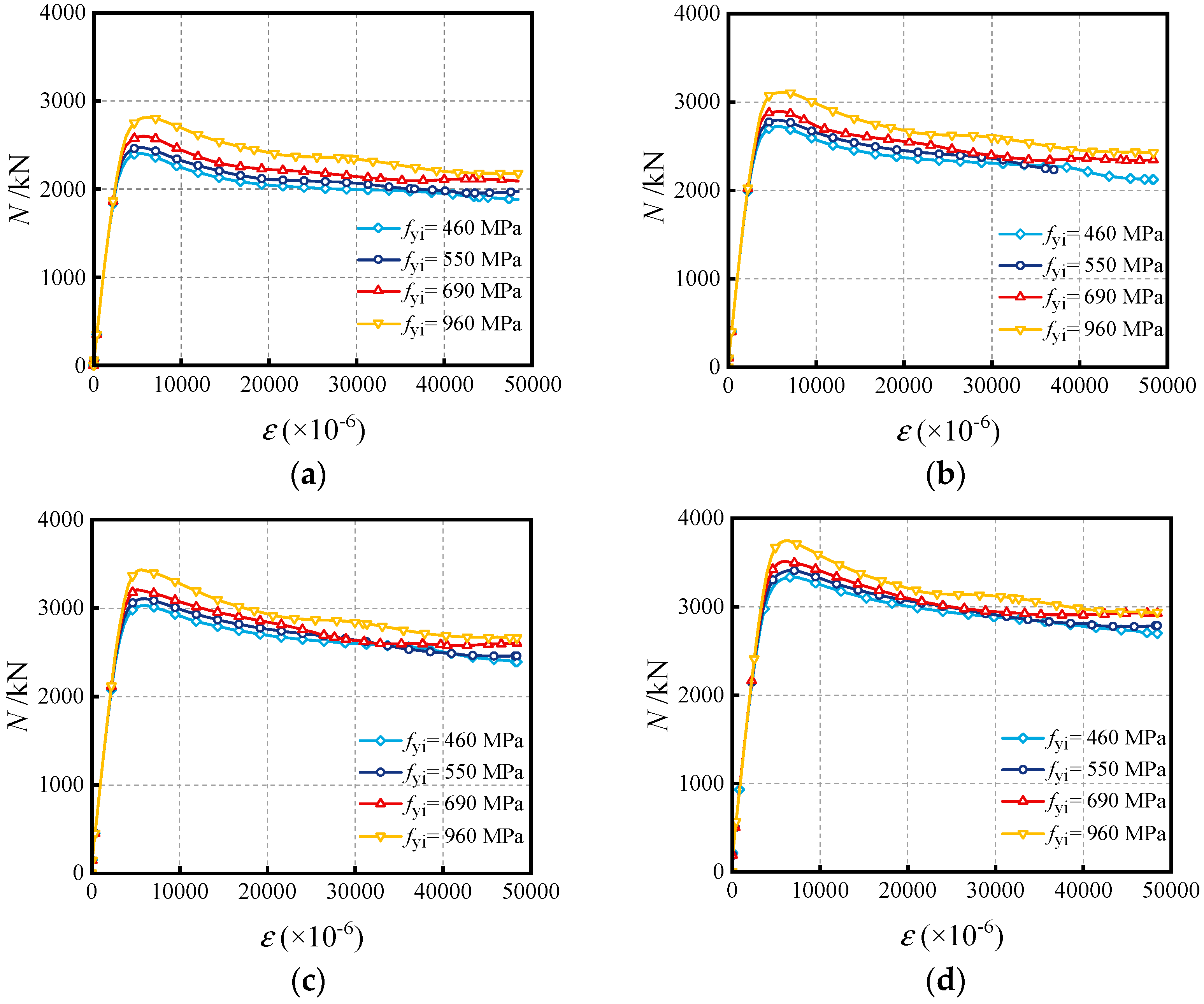
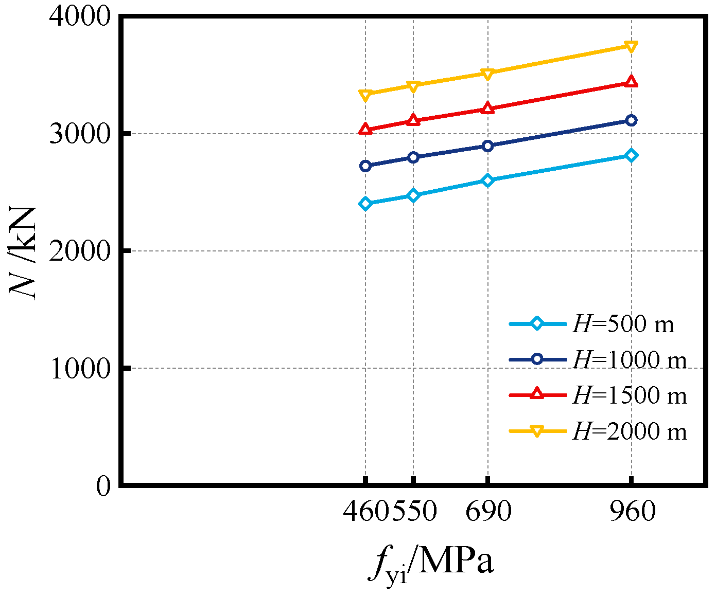
4.3. Influence of Yield Strength of Inner Tube (fyi)

The influence of the yield strength of the inner tube (fyi) shown in Figure 12 and Figure 13 has a similar effect on the full-range load–displacement curves and bearing capacity, compared to the influence of fyo as discussed in Section 4.2. The axial bearing capacity at the condition of water depth H = 1000 m is amplified by 2.70%, 6.27%, and 14.28% when increasing fyi from 460 MPa to 550 MPa, 690 MPa, and 960 MPa, respectively. For the SSCDS composite tubes with fyi = 550 MPa, increasing the water depth from 500 m to 1000 m enhances the bearing capacity by 13.10%, 25.64%, and 37.93%, respectively.

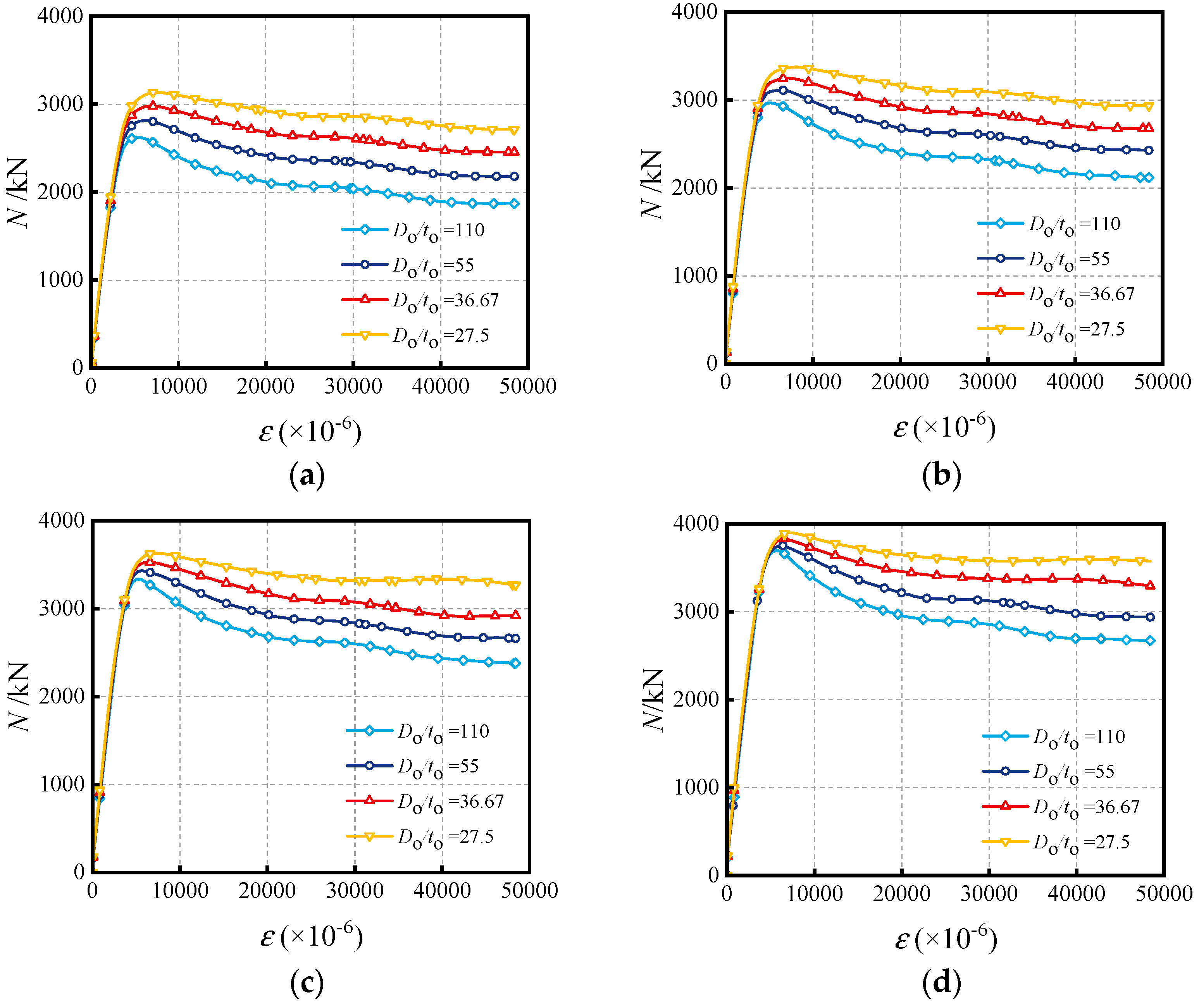
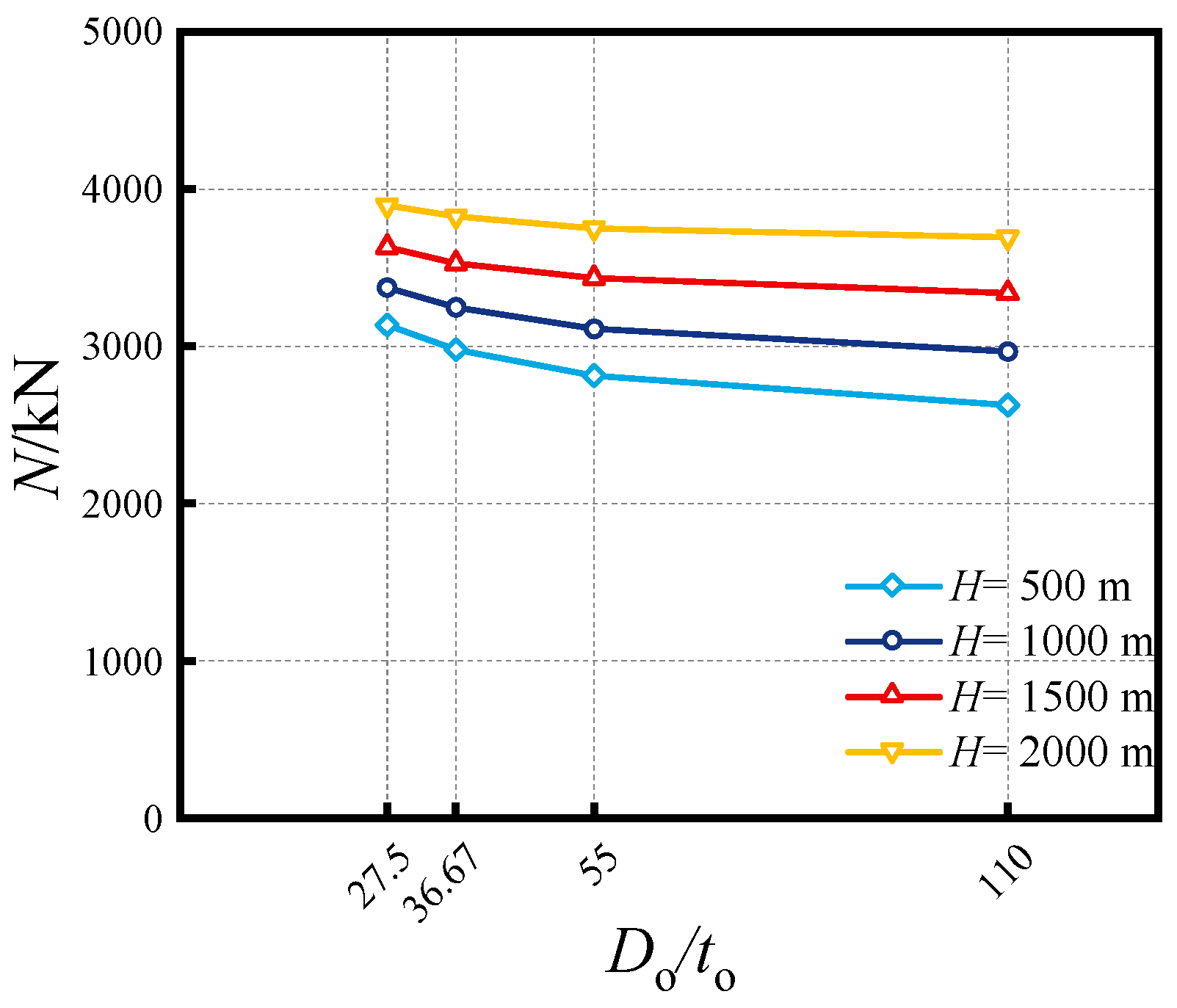
4.4. Influence of Do/to Ratio

Adjustments to the Do/to ratios were accomplished by keeping the diameter (Do) constant while varying the thickness (to). As displayed in Figure 14, increasing the Do/to ratio of SSCDS composite tubes can reduce the bearing capacity and accelerate the degradation behavior after the post-peak stage. This is due to the reduction of the confinement coefficient induced by reducing the cross-sectional area of the outer tube while increasing the Do/to ratio. For example, in Figure 15, at a water depth of 1000 m, enhancing the Do/to ratio from 27.5 to 36.67, 55, and 110 gradually reduces the axial compressive strength by 3.73%, 7.79%, and 12.10%. The high water depth, namely, the higher outer hydraulic pressure, also increases its bearing capacity. For the SSCDS composite tubes with a Do/to ratio of 55, its axial strength is improved by 10.61%, 22.10%, and 33.33% with a deepening of the water depth from 500 m to 1000 m, 1500 m and 2000 m, respectively.

4.5. Influence of Di/ti Ratio

In this section, modifications to the Di/ti ratios were achieved by maintaining a constant diameter (Di) of inner tube while systematically altering its thickness (ti). The influence of Di/ti ratio, as illustrated in Figure 16 and Figure 17, exhibits a comparable trend in both the load–displacement curves and the overall bearing capacity compared to the influence of the Do/to ratio in Section 4.4. In Figure 17, at a water depth of 1000 m, enhancing the Di/ti ratio from 11.25 to 15, 22.5, and 45 gradually reduces the axial compressive strength by 9.65%, 19.66%, and 29.26%. For the SSCDS composite tubes with a Di/ti ratio of 45, the axial strength is enhanced by 13.90%, 26.90%, and 39.89% when increasing the water depth from 500 m to 1000 m, 1500 m, and 2000 m, respectively.

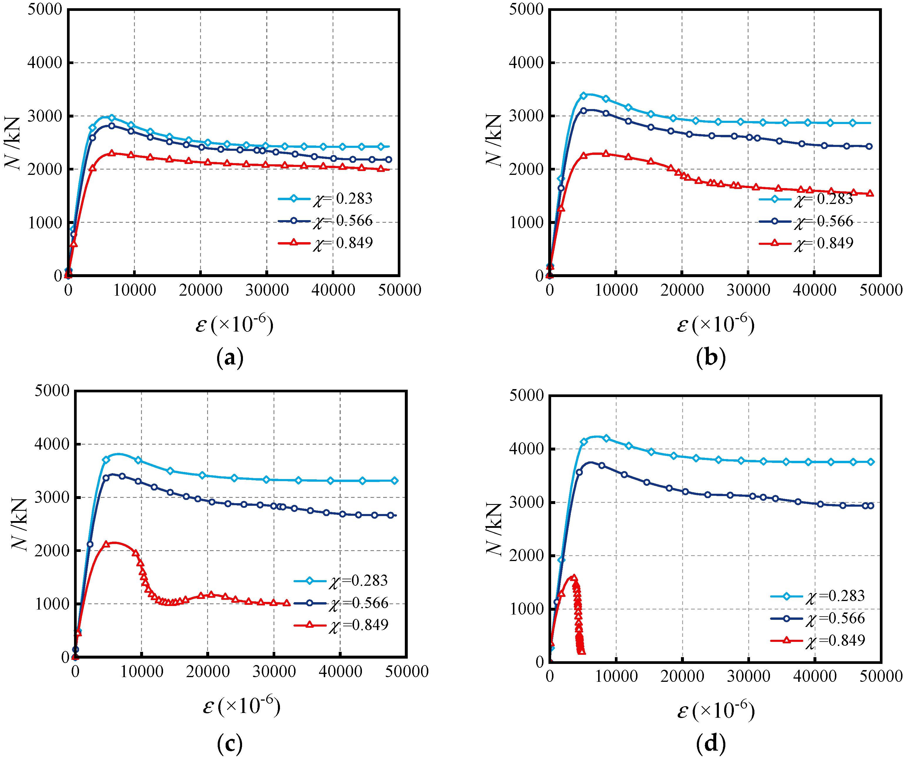
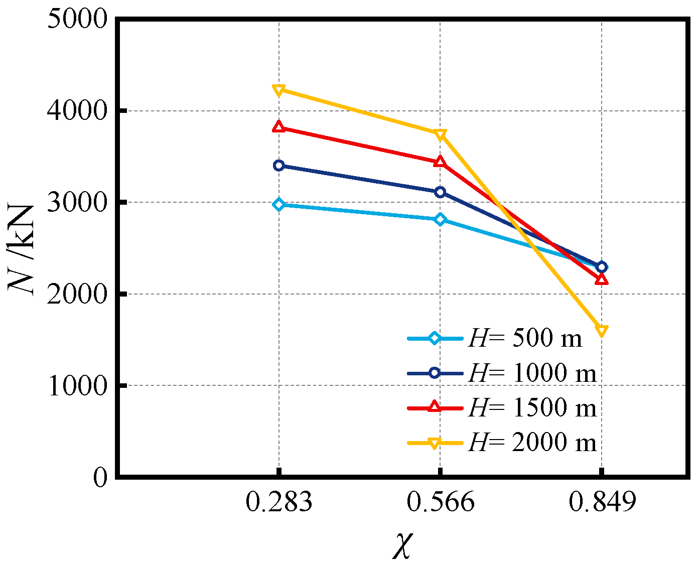
4.6. Influence of Hollow Ratio (χ)

In this section, the hollow ratio χ is determined by χ = Di/(Do − 2to). The adjustment to the hollow ratio is conducted by changing the diameter Di only. The influence of the hollow ratio on full-range curves is shown in Figure 18. It can be seen that as the hollow ratio increases, the bearing capacity of the specimen decreases. Even under high hydraulic water pressure, the load versus displacement curve of the specimen shows a significant drop phenomenon, e.g., in the SSCDS composite tubes with a hollow ratio of 0.849 at the water depths of 1500 m and 2000 m (Figure 18b,c). The increased external hydraulic pressure exacerbates radial deformation, and the SSCDS composite tubes, characterized by high hollow ratios, experience a substantial reduction in cross-sectional stiffness. Consequently, their compressive behavior is prone to failure and instability. The influence of hollow ratio on bearing capacity is depicted in Figure 19. At a water depth of 1000 m, the axial bearing capacity is, respectively, decreased by 8.56% and 32.63% while enhancing the hollow ratio from 0.283 to 0.566 and 0.849. The larger the hollow ratio, the smaller the increment in bearing capacity with increasing water depth, and it may even decrease, e.g., for the SSCDS composite tubes with a hollow ratio of 0.849, its bearing capacity is increased by 0.05% with a deepening of water depth from 500 m to 1000 m. However, as the water depth continues to increase, the bearing capacity gradually decreases; e.g., the capacity is decreased by 6.28% and 29.86% with the increase in water depth from 1000 m to 1500 m and 2000 m. The hollow ratio of the deep-sea environment should be strictly controlled for the SSCDS composite tubes.

5. Strength Model of Axial Bearing Capacity

Until now, there is no design code suitable for the bearing capacity calculation of SSCDS composite tubes subjected to dual hydraulic pressure. The prevailing design methods of traditional concrete-filled double-skin carbon steel tubes or concrete-filled stainless steel tubes are grounded in terrestrial engineering principles, thereby neglecting the dynamic confinement effects resulting from the dual hydraulic pressures [31,32]. A practical design method for the compressive bearing capacity is established for SSCDS composite tubes exposed to dual hydraulic pressures. It can be found as follows.
The strength contributions of the outer stainless steel tube, sandwich concrete and inner carbon steel tube can be inferred from the total bearing capacity (NP) of SSCDS composite tubes,
N P = η ( N so + N si + N sc )
where Nso is the strength of the outer tube; Nsi is the strength of the inner tube; Nsc is the sandwich concrete strength; η is the adjustment factor influenced by hydraulic pressure and hollow ratio. By analyzing the FE data and test data, the adjustment factor η is highly correlated to the hollow ratio (χ) and outer hydraulic pressure (Po); in this paper, it is derived from the nonlinear fitting analysis,
η = 1 χ 43.43 P o 2.27
In Equation (11), the contributions of Nso and Nsi can be respectively calculated as follows:
N so = f yo A so
N si = f yi A si
where Aso and Asi are, respectively, the cross-sectional areas of the outer tube and inner tube.
As for the sandwich concrete in SSCDS composite tubes, it is in the confinement state induced by the passive action of axial loading and the active action of dual hydraulic pressures. The maximum confining stress (σr) from the outer tube to the sandwich concrete can be determined as the SSCDS composite tube is in a concentric compression state [33]:
σ r = 0.38 t o f yo D o 2 t o
Subsequently, the restrained condition of sandwich concrete is further enhanced while the SSCDS composite tube is exposed to dual hydraulic pressures. Through the FE analysis, the confining stresses from double-skin tubes to sandwich concrete can be approximately equal to the applied initial dual hydraulic pressures. In that case, the axial strength of sandwich concrete will be improved due to the dual hydraulic pressures and axial compression, which can be calculated as follows [34]:
f cc = f c + 4.1 ( P o + P i 2 ) + σ r
where fcc is the confining strength of sandwich concrete; fc is the compressive strength of the plain concrete cylinder; Pi is the inner medium pressure of oil and gas. Then, the strength contribution of sandwich concrete is as follows:
N sc = f cc A c
where Ac is the area of sandwich concrete. Finally, the predicted axial compression strength of SSCDS composite tubes influenced by dual hydraulic pressures can be obtained by Equation (11). The prediction accuracy was validated by the FE data and test results in Figure 20, where the predicted average of the proposed model is 0.988 and the variance is 0.0086. The validation results of the proposed strength model’s accuracy and applicability are favorable, providing an important bearing capacity assessment basis for engineering construction. It is worth noting that the scope of this study is as follows: fc = 40~100 MPa; fyi = 460~960 MPa; fyo = 280~480 MPa; Do/to = 27.5~110; Di/ti = 11.25~45; χ = 0.283~0.849; water depth H = 0~2000 m; and the internal medium pressure does not exceed 10 MPa. This study mainly relies on numerical simulations and theoretical analysis, and further experimental tests can validate the effectiveness of the results presented in this paper.

6. Conclusions

This paper has analyzed the concentric compressive behaviors of SSCDS composite tubes influenced by dual hydraulic pressures. The present study allows for the following conclusion to be drawn:
(1)
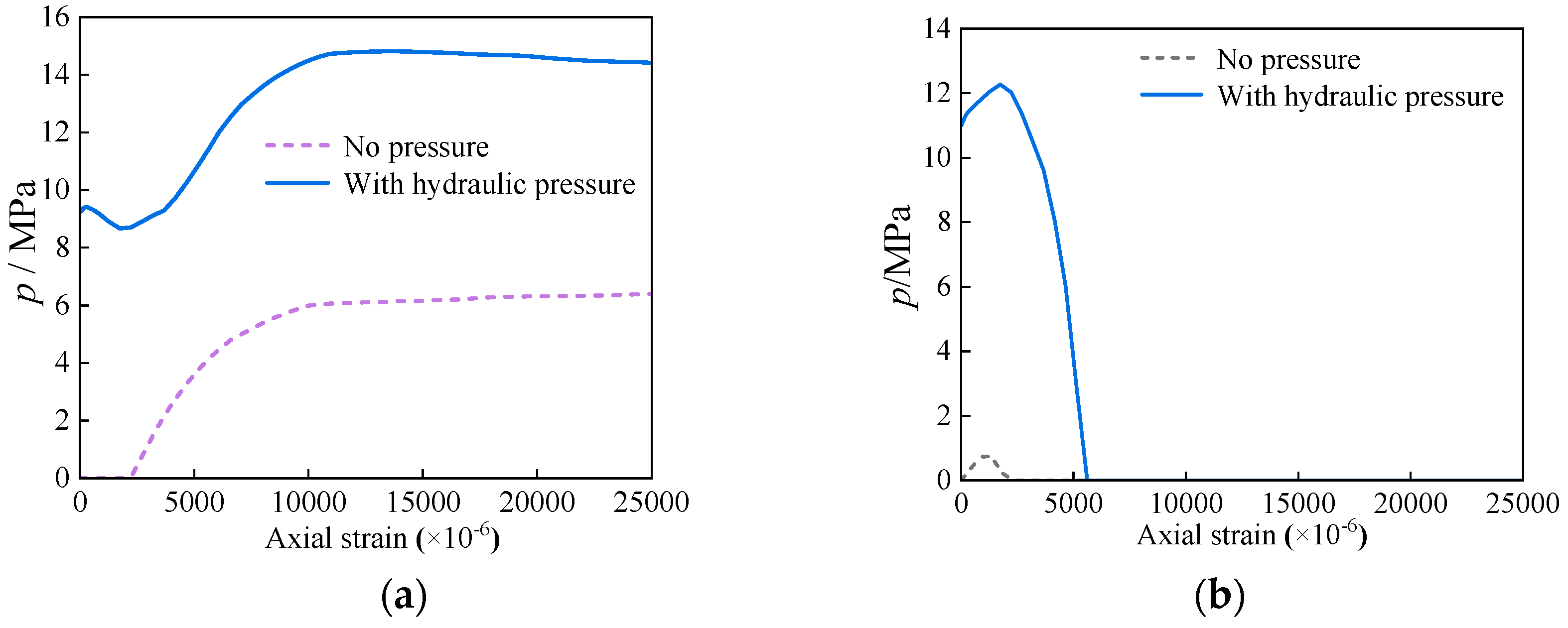
The verified FE model is employed to analyze the concentric compressive mechanism of the SSCDS composite tube in an environment of dual hydraulic pressures. The full-range mechanism reveals that the application of dual hydraulic pressures enhances the confinement of the sandwich concrete, leading to an elevated axial compressive strength when compared to the unpressurized benchmark. The dual hydraulic pressures results in an uneven distribution of stress within the sandwich concrete along the radial axis, leading to a condition of increased non-uniformity in constraint;
(2)
The effects of critical parameters are analyzed, encompassing the impact of the Do/to ratio, Di/ti ratio, fyo, fyi, fc and χ at various water depths. Increasing material strengths of fyo, fyi and fc can enhance the compressive capacity, while enhancing the diameter-to-thickness ratio (Do/to, Di/ti) can decrease the capacity. The synergistic effect of external hydraulic pressure and internal fluid pressure can augment the confinement efficacy of SSCDS composite tubes, thereby enhancing their axial load-bearing capacity. As the hollow ratio increases, the augmentation of bearing capacity diminishes with greater water depths;
(3)
A practical methodology that integrates the effects of dual hydraulic pressures has been developed and validated for the members of SSCDS composite tubes. It serves as an initial framework for the safety assessment of deep-water engineering applications (e.g., submarine pipeline).

Author Contributions

Conceptualization, J.-T.W.; methodology, J.-T.W., Y.Y. and K.-L.Y.; validation, J.-T.W., Y.Y. and K.-L.Y.; formal analysis, J.-T.W., Y.Y., K.-L.Y. and D.-L.H.; investigation, Y.Y., K.-L.Y., D.-L.H., L.-B.X. and J.-X.L.; resources, J.-T.W.; writing—original draft preparation, J.-T.W., Y.Y. and K.-L.Y.; writing—review and editing, J.-T.W., Y.Y., K.-L.Y., D.-L.H., L.-B.X. and J.-X.L.; visualization, J.-T.W., Y.Y. and K.-L.Y.; supervision, J.-T.W.; project administration, J.-T.W.; funding acquisition, J.-T.W. All authors have read and agreed to the published version of the manuscript.

Funding

This research was funded by Shaanxi Province High-Level Talent Youth Program (Z20240589), and Fujian Province Housing and Urban-Rural Development Industry Science and Technology Plan Project (2022-K-130).

Institutional Review Board Statement

Not applicable.

Informed Consent Statement

Not applicable.

Data Availability Statement

The data presented in this study are available on request from the corresponding author.

Acknowledgments

The authors acknowledge the numerical assistance from the team members of Xi’an University of Architecture and Technology.

Conflicts of Interest

The authors declare no conflicts of interest. Author Jun-Xin Li was employed by the company of Zhongmin Mingtai Group Co., Ltd. The remaining authors declare that the research was conducted in the absence of any commercial or financial relationships that could be construed as a potential conflict of interest.

References

  1. Li, R.; Chen, B.Q.; Guedes Soares, C. Design Equation of Buckle Propagation Pressure for Pipe-in-Pipe Systems. J. Mar. Sci. Eng. 2023, 11, 622. [Google Scholar] [CrossRef]
  2. Wang, Y.; Huang, J.; Duan, M.; Sun, C.; Wang, X. Experimental and numerical study of lateral indentation for pipe-in-pipe structures. J. Mar. Sci. Eng. 2023, 11, 98. [Google Scholar] [CrossRef]
  3. Fan, J.; Chang, X.; Chen, B.; Yang, Y.; Li, Y. Stability and modal evolution characteristics of pipe-in-pipe system with internal intermediate support. Eng. Struct. 2024, 304, 117577. [Google Scholar] [CrossRef]
  4. Zhao, H.; Wang, R.; Lam, D.; Hou, C.C.; Zhang, R. Behaviours of circular CFDST with stainless steel external tube: Slender columns and beams. Thin Wall. Struct. 2021, 158, 107172. [Google Scholar] [CrossRef]
  5. Tien, C.M.T.; Manalo, A.; Dixon, P.; Tafsirojjaman, T.; Karunasena, W.; Flood, W.W.; Ahmadi, H.; Kiriella, S.; Salah, A.; Wham, B.P. Effects of the legacy pipe ends on the behaviour of pipe-in-pipe repair systems under internal pressure. Eng. Fail. Anal. 2023, 144, 106957. [Google Scholar] [CrossRef]
  6. Mohammed, A.I.; Bartzas, K.; Johnson, C.; Spence, S.; Skyes, P.; Kidd, G.; McConnachie, J.; Njuguna, J. Structural response of a compliant pipe-in-pipe under frictionless and frictional conditions of the seabed. Ocean Eng. 2023, 276, 114020. [Google Scholar] [CrossRef]
  7. Sun, M.M.; Fang, H.Y.; Wang, N.N.; Du, X.M.; Zhao, H.S.; Zhai, K.J. Limit state equation and failure pressure prediction model of pipeline with complex loading. Nat. Commun. 2024, 15, 4473. [Google Scholar] [CrossRef]
  8. Pagoulatou, M.; Sheehan, T.; Dai, X.H.; Lam, D. Finite element analysis on the capacity of circular concrete-filled double-skin steel tubular (CFDST) stub columns. Eng. Struct. 2014, 72, 102–112. [Google Scholar] [CrossRef]
  9. Tran, V.L.; Kim, S.E. Efficiency of three advanced data-driven models for predicting axial compression capacity of CFDST columns. Thin Wall. Struct. 2020, 152, 106744. [Google Scholar] [CrossRef]
  10. Wang, W.D.; Fan, J.H.; Shi, Y.L.; Xian, W. Research on mechanical behaviour of tapered concrete-filled double skin steel tubular members with large hollow ratio subjected to bending. J. Constr. Steel Res. 2021, 182, 106689. [Google Scholar] [CrossRef]
  11. Shi, Y.L.; Zhang, C.F.; Xian, W.; Wang, W.D. Research on mechanical behavior of tapered concrete-filled double skin steel tubular members under eccentric compression. J. Build. Struct. 2021, 42, 155–164. (In Chinese) [Google Scholar]
  12. Li, W.; Li, W.J.; Xu, L.F.; Wang, F.C. Performance of CFDST beams using high-strength steel under bending. Structures 2021, 34, 2644–2655. [Google Scholar] [CrossRef]
  13. Ci, J.; Ahmed, M.; Tran, V.L.; Jia, H.; Chen, S. Axial compressive behavior of circular concrete-filled double steel tubular short columns. Adv. Struct. Eng. 2022, 25, 259–276. [Google Scholar] [CrossRef]
  14. Fan, J.H.; Wang, W.D.; Shi, Y.L.; Ji, S.H. Torsional behaviour of tapered CFDST members with large void ratio. J. Build. Eng. 2022, 52, 104434. [Google Scholar] [CrossRef]
  15. Lu, G.; Su, M.; Zhou, X.; Deng, X.; Bai, Y.; Wang, Y. Numerical analysis on torsional behavior of rectangular and square CFDST members. J. Constr. Steel Res. 2022, 193, 107294. [Google Scholar] [CrossRef]
  16. Wang, X.T.; Peng, X.; Zhang, J.P.; Yan, C.Z.; Li, X.G.; Yan, F.J. An experimental study on the flexural behavior of tapered high-strength thin-walled concrete-filled double skin steel tubular members. Prog. Steel Build. Struct. 2022, 24, 24–33. (In Chinese) [Google Scholar]
  17. Zheng, Y.; Wang, C.; Chen, M. Flexural strength and stiffness of circular double-skin and double-tube concrete-filled steel tubes. Mar. Struct. 2022, 81, 103126. [Google Scholar] [CrossRef]
  18. Deng, R.; Zhou, X.H.; Wang, Y.H.; Bai, J.L.; Deng, X.W. Experimental study on tapered concrete-filled double skin steel tubular columns under torsion. Thin Wall. Struct. 2022, 177, 109444. [Google Scholar] [CrossRef]
  19. Cheng, Z.; Wang, F.; Zhang, D. Analytical model for axially compressed circular concrete-filled double skin steel tubes (CFDSTs): Insights from concrete non-uniformly confined states. Thin Wall. Struct. 2023, 192, 111106. [Google Scholar] [CrossRef]
  20. Yilmaz, B.C.C.; Binbir, E.; Guzelbulut, C.; Yildirim, H.; Celik, O.C. Circular concrete-filled double skin steel tubes under concentric compression: Tests and FEA parametric study. Compos. Struct. 2023, 309, 116765. [Google Scholar] [CrossRef]
  21. Han, L.H.; Ren, Q.X.; Li, W. Tests on stub stainless steel–concrete–carbon steel double-skin tubular (DST) columns. J. Constr. Steel Res. 2011, 67, 437–452. [Google Scholar] [CrossRef]
  22. Wang, F.; Young, B.; Gardner, L. Compressive testing and numerical modelling of concrete-filled double skin CHS with austenitic stainless steel outer tubes. Thin Wall. Struct. 2019, 141, 345–359. [Google Scholar] [CrossRef]
  23. Wang, F.; Young, B.; Gardner, L. CFDST sections with square stainless steel outer tubes under axial compression: Experimental investigation, numerical modelling and design. Eng. Struct. 2020, 207, 110189. [Google Scholar] [CrossRef]
  24. Le, T.T.; Patel, V.I.; Liang, Q.Q.; Huynh, P. Axisymmetric simulation of circular concrete-filled double-skin steel tubular short columns incorporating outer stainless-steel tube. Eng. Struct. 2021, 227, 111416. [Google Scholar] [CrossRef]
  25. Zhou, F.; Lama, L.; Zhao, K. Design of stainless steel CHS-concrete infill-carbon steel CHS double-skin stub columns. Eng. Struct. 2023, 278, 115479. [Google Scholar] [CrossRef]
  26. Wang, F.C.; Han, L.H. Analytical behavior of carbon steel-concrete-stainless steel double-skin tube (DST) used in submarine pipeline structure. Mar. Struct. 2019, 63, 99–116. [Google Scholar] [CrossRef]
  27. Wang, J.T.; Yang, K.L.; Sun, J.Y. Compressive Behavior of Stainless Steel–Concrete–Carbon Steel Double-Skin Tubular (SCCDST) Members Subjected to External Hydraulic Pressure. J. Mar. Sci. Eng. 2024, 12, 406. [Google Scholar] [CrossRef]
  28. Shi, Y.J.; Wang, M.; Wang, Y.Q. Study on constitutive model of structural steel under cyclic loading. Eng. Mech. 2012, 29, 92–98. (In Chinese) [Google Scholar] [CrossRef]
  29. Patel, V.I.; Hassanein, M.F.; Thai, H.T.; Al Abadi, H.; Paton-Cole, V. Behaviour of axially loaded circular concrete-filled bimetallic stainless-carbon steel tubular short columns. Eng. Struct. 2017, 147, 583–597. [Google Scholar] [CrossRef]
  30. Han, L.H. Concrete Filled Steel Tubular Structures—Theory and Practice; Science Press: Beijing, China, 2016. (In Chinese) [Google Scholar]
  31. T/CCES 7-2020; China Civil Engineering Society. Technical Specification for Concrete-Filled Double Skin Steel Tubular Structures. China Architecture & Building Press: Beijing, China, 2020. (In Chinese)
  32. T/CECS 952-2021; China Association for Engineering Construction Standardization. Technical Specification for Concrete-Filled Stainless Steel Tubular Structures. China Architecture & Building Press: Beijing, China, 2022. (In Chinese)
  33. Sakino, K.; Nakahara, H.; Morino, S.; Nishiyama, I. Behavior of centrally loaded concrete-filled steel-tube short columns. J. Struct. Eng. 2004, 130, 180–188. [Google Scholar] [CrossRef]
  34. Richart, F.E.; Brandtzæg, A.; Brown, R.L. A Study of the Failure of Concrete Under Combined Compressive Stresses; University of Illinois, Bulletin: Champaign, IL, USA, 1928. [Google Scholar]
Figure 1. Stress–strain relationships of carbon/stainless steel.
Jmse 12 02140 g001
Figure 2. Established FE model.
Jmse 12 02140 g002
Figure 3. Verification on curves of load versus displacement. (a) AC165×3-HC22×4-C40; (b) AC165×3-HC22×4-C80; (c) AC165×3-HC22×4-C120.
Jmse 12 02140 g003
Figure 4. Verification on failure mode.
Jmse 12 02140 g004
Figure 5. Axial curves of compression versus strain influenced by dual hydraulic pressures.
Jmse 12 02140 g005
Figure 6. Confinement action effected by dual hydraulic pressures. (a) Normal stress at the surface between outer tube and concrete; (b) normal stress at the surface between inner tube and concrete.
Jmse 12 02140 g006
Figure 7. Stress distribution of encased concrete at peak load.
Jmse 12 02140 g007
Figure 8. Influence of fc (a) at water depth of 500 m; (b) at water depth of 1000 m; (c) at water depth of 1500 m; (d) at water depth of 2000 m.
Jmse 12 02140 g008
Figure 9. Influence of fc on axial compression strength at various water depths.
Jmse 12 02140 g009
Figure 10. Influence of fyo (a) at water depth of 500 m; (b) at water depth of 1000 m; (c) at water depth of 1500 m; (d) at water depth of 2000 m.
Jmse 12 02140 g010
Figure 11. Influence of fyo on axial compression strength at various water depths.
Jmse 12 02140 g011
Figure 12. Influence of fyi (a) at water depth of 500 m; (b) at water depth of 1000 m; (c) at water depth of 1500 m; (d) at water depth of 2000 m.
Jmse 12 02140 g012
Figure 13. Influence of fyi on axial compression strength at various water depths.
Jmse 12 02140 g013
Figure 14. Influence of Do/to ratios (a) at water depth of 500 m; (b) at water depth of 1000 m; (c) at water depth of 1500 m; (d) at water depth of 2000 m.
Jmse 12 02140 g014
Figure 15. Influence of Do/to ratios on axial compression strength at various water depths.
Jmse 12 02140 g015
Figure 16. Influence of Di/ti ratios (a) at water depth of 500 m; (b) at water depth of 1000 m; (c) at water depth of 1500 m; (d) at water depth of 2000 m.
Jmse 12 02140 g016
Figure 17. Influence of Di/ti ratios on axial compression strength at various water depths.
Jmse 12 02140 g017
Figure 18. Influence of χ (a) at water depth of 500 m; (b) at water depth of 1000 m; (c) at water depth of 1500 m; (d) at water depth of 2000 m.
Jmse 12 02140 g018
Figure 19. Influence of χ on axial compression strength at various water depths.
Jmse 12 02140 g019
Figure 20. Validation of proposed strength model.
Jmse 12 02140 g020
Table 1. Verification of bearing capacity.
Specimen [21]Length/mmOuter Tube/mmInner Tube/mmMaterial Strength/MPaTest Strength NT/kNSimulated Strength NFE/kNNFE/NT
DotoDitifyofyifc
AC140×3-HC22×4-C40350140.22.9222.14.0930079440.514101398.480.9918
AC140×3-HC22×4-C80350140.22.9122.14.1030079479.918451845.941.0005
AC140×3-HC22×4-C120350140.22.8922.14.08300794115.623212322.871.0008
AC140×3-HC32×6-C40350140.32.8932.05.4830061940.514231470.331.0333
AC140×3-HC32×6-C80350140.22.9231.95.2730061979.920122016.151.0021
AC140×3-HC32×6-C120350140.12.9131.95.36300619115.625372513.090.9906
AC140×3-HC38×8-C40350140.12.9138.17.6330043340.516261562.520.9610
AC140×3-HC38×8-C80350140.12.9038.07.5130043379.920832078.900.9980
AC140×3-HC38×8-C120350140.22.9037.97.39300433115.625002537.381.0150
AC140×3-HC55×11-C40350140.22.9055.110.6230073940.525432541.380.9994
AC140×3-HC55×11-C80350140.12.9055.210.7630073979.927752572.600.9919
AC140×3-HC89×4-C40350140.12.8789.03.89300102940.520252008.070.9916
AC140×3-HC89×4-C80350140.12.8689.13.91300102979.921072157.631.0240
AC140×3-HC89×4-C120350140.22.8889.13.913001029115.621952152.460.9806
AC165×3-HC22×4-C40413165.32.9422.04.1427679440.517501613.740.9221
AC165×3-HC22×4-C80413165.22.9422.14.0927679479.924132374.280.9840
AC165×3-HC22×4-C120413165.32.9422.14.04276794115.629112914.871.0013
AC165×3-HC32×6-C40413165.32.9331.95.3527661940.519431914.140.9851
AC165×3-HC32×6-C40R413165.32.9431.95.3927661940.518911853.360.9801
AC165×3-HC32×6-C80413165.32.9431.85.2527661979.925502577.291.0107
AC165×3-HC89×4-C40413165.52.9289.03.92276102940.523752330.040.9811
AC165×3-HC89×4-C80413165.42.9189.13.91276102979.925802598.901.0073
AC165×3-HC89×4-C120413165.22.9288.93.882761029115.626712685.271.0053
Mean 0.9938
Variance 0.0005
Table 2. Summary of parameter study.
Water Depths (H)/mDo/toDi/tifyo/MPafyi/MPafc/MPaχ
500; 1000; 1500; 2000110; 55; 36.67; 27.545; 22.5; 15; 11.25280; 350; 420; 480460; 550; 690; 96040; 60; 80; 1000.283; 0.566; 0.849
Note: Details of benchmark specimen according to Section 3.
Disclaimer/Publisher’s Note: The statements, opinions and data contained in all publications are solely those of the individual author(s) and contributor(s) and not of MDPI and/or the editor(s). MDPI and/or the editor(s) disclaim responsibility for any injury to people or property resulting from any ideas, methods, instructions or products referred to in the content.

