
A Numerical Method on Large Roll Motion in Beam Seas Under Intact and Damaged Conditions

Abstract
1. Introduction
2. Mathematical Model
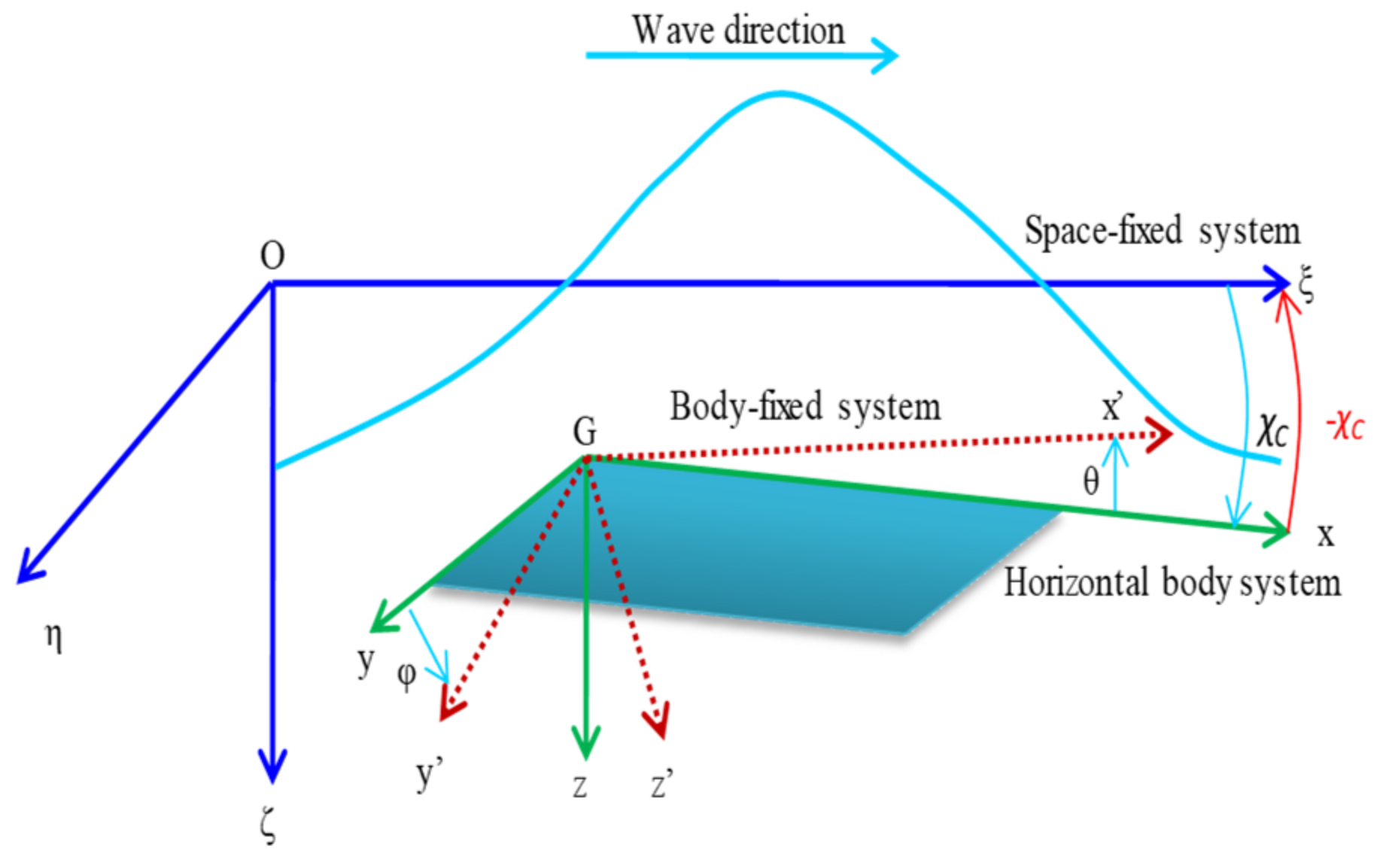
2.1. Coordinate Systems
2.2. Mathematical Model in Regular Waves
2.3. Mathematical Model in Irregular Waves
2.4. Excited Wave Force
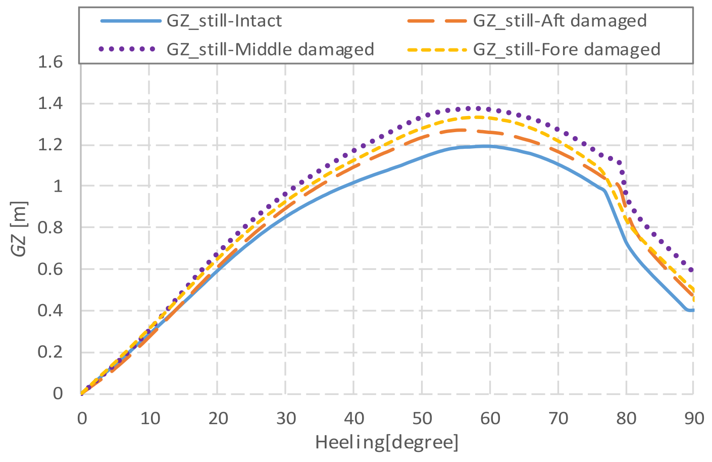
2.5. Roll Restoring Force Variation
2.6. Roll-Damping
3. Subject Ship
4. Simulations and Discussions
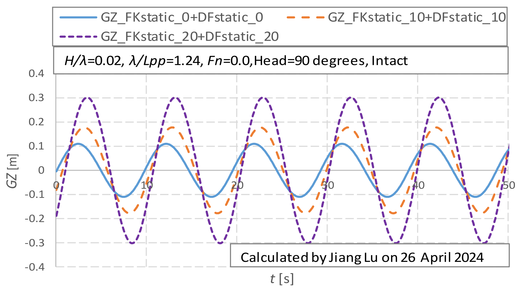
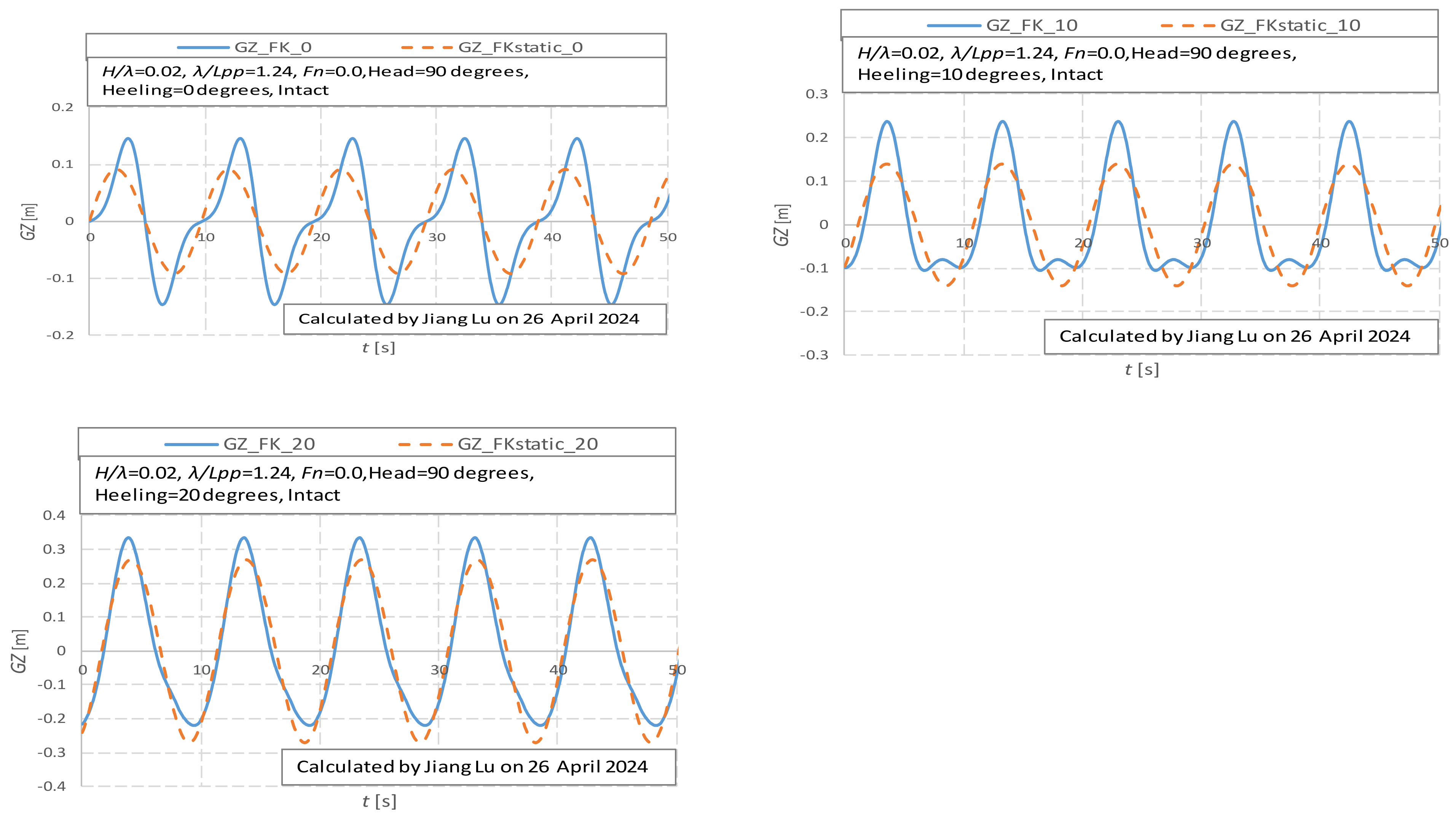
4.1. The Roll-Restoring Variation
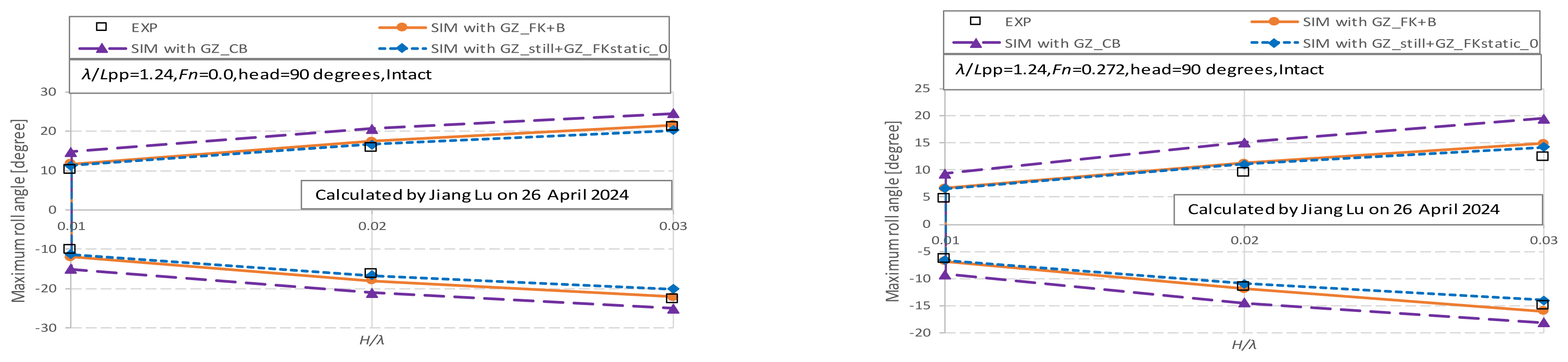
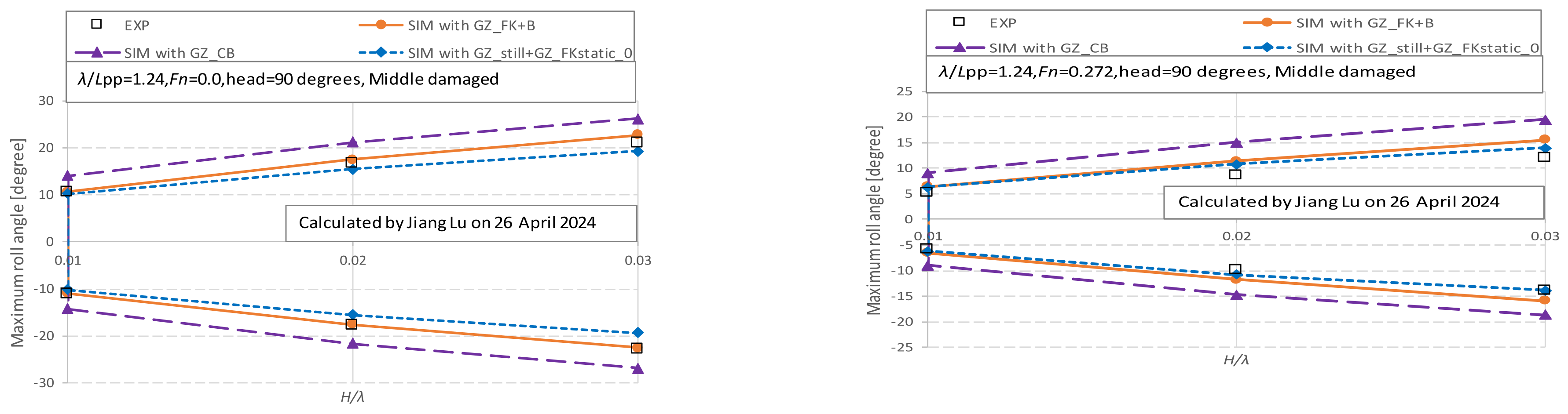
4.2. The Roll Motions in Regular Beam Waves
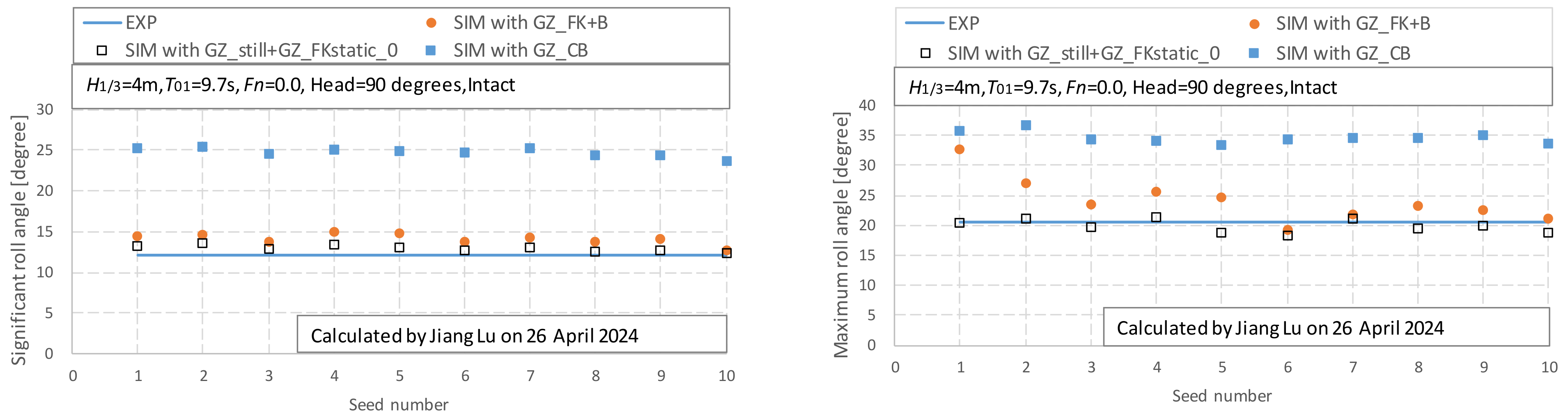
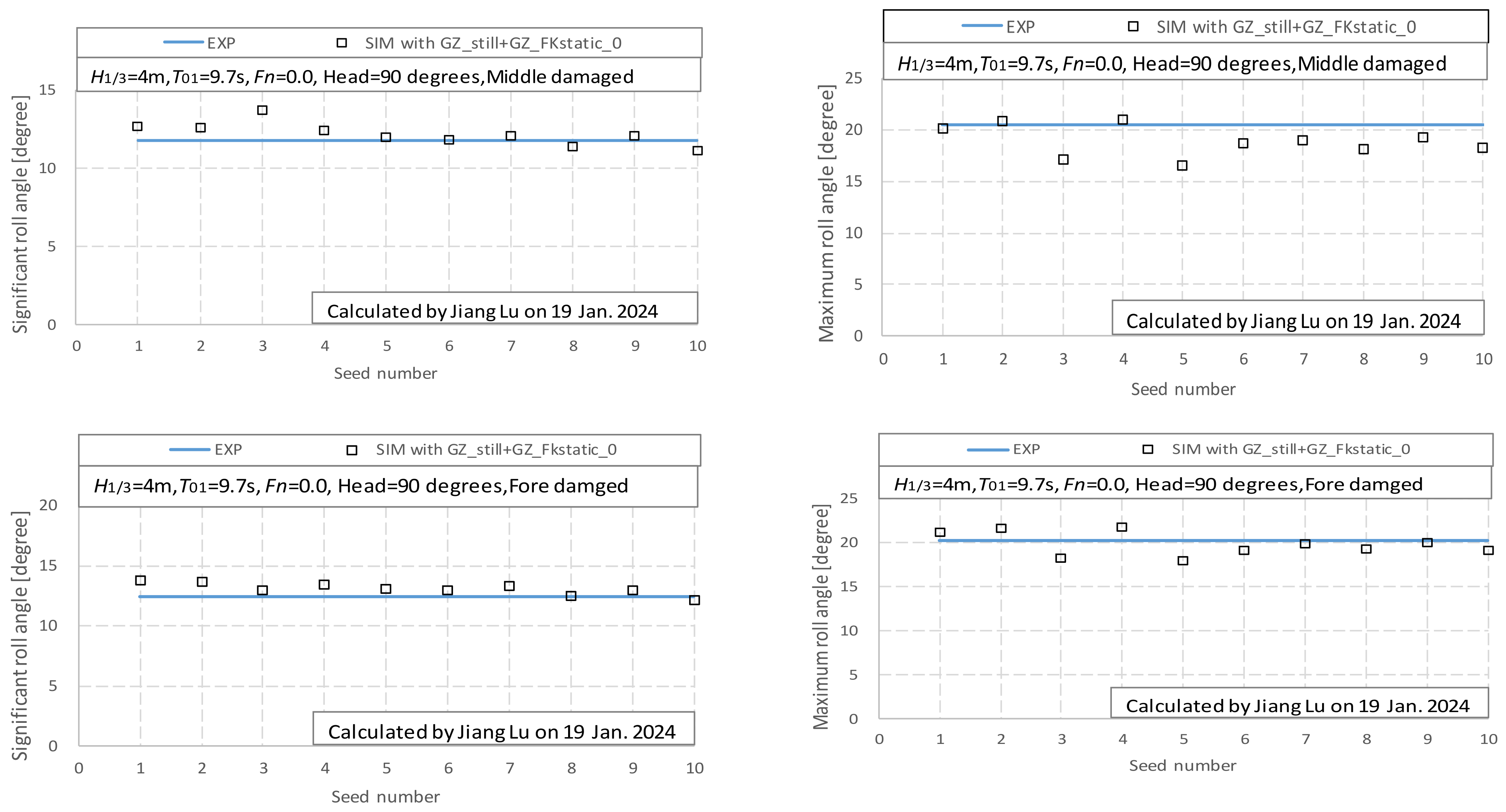
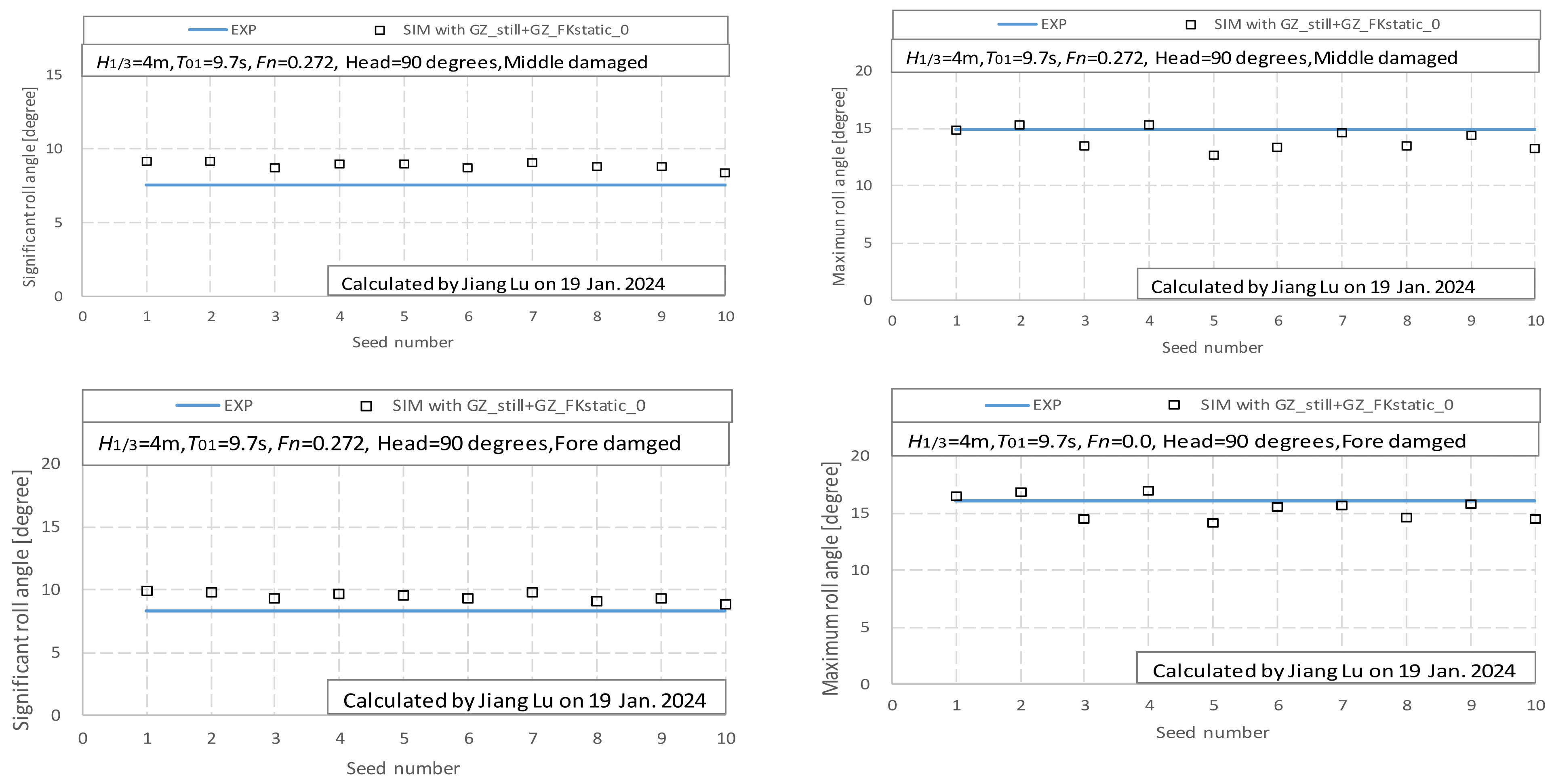
4.3. The Roll Motions in Irregular Beam Waves
5. Conclusions
- A sway–heave–pitch–roll–yaw coupled equation named 5-DOF can predict the large roll motion in regular and irregular beam seas under intact conditions.
- The sway-roll-yaw coupled motion with the roll-righting arm in still water named 3-DOF can be used to predict the large roll motion in regular and irregular beam seas under damaged conditions with the initial hydrostatic parameters under the damaged condition, especially the mean roll period and the roll-damping coefficients, which consider the effect of water ingress and egress in calm water during the free roll decay test.
- The numerical mathematical model for predicting the significant roll motion in beam seas under intact and damaged conditions could be unified with the sway-roll-yaw coupled motion with the roll-righting arm in still water.
Author Contributions
Funding
Institutional Review Board Statement
Informed Consent Statement
Data Availability Statement
Conflicts of Interest
References
- IMO. Interim Guidelines on the Second-Generation Intact Stability Criteria; Msc.1/Circ.1627; IMO: London, UK, 2020. [Google Scholar]
- Umeda, N.; Koga, S.; Ueda, J.; Maeda, E.; Tsukamo, I.; Paroka, D. Methodology for Calculating Capsizing Probability for a Ship under Dead Ship Condition. In Proceedings of the 9th International Ship Stability Workshop, Hamburg, Germany, 30–31 August 2007; p. 1.2.1. [Google Scholar]
- Japan. Draft Direct Assessment on Stability under Dead Ship Condition and Its Numerical Validation; SLF 53/INF.10, Annex7; IMO: London, UK, 2010. [Google Scholar]
- Japan. Review of Draft Leve2 and Level 3 Criteria on Stability under Dead Ship Condition; SLF 54/INF.12, Annex19; IMO: London, UK, 2011. [Google Scholar]
- Italy. Comments on Japan’s Submission for Draft Leve2 and Level 3 Criteria on Stability Under Dead Ship Condition; SLF 54/INF.12 Annex20; IMO: London, UK, 2011. [Google Scholar]
- Kubo, T.; Umeda, N.; Izawa, S.; Matsuda, A. Total Stability Failure Probability of a Ship in Irregular Beam Wind and Waves: Model Experiment and Numerical Simulation. In Proceedings of the 11th International Conference on the Stability of Ships and Ocean Vehicles, Athens, Greece, 23–28 September 2012; pp. 39–46. [Google Scholar]
- Ogawa, Y.; de Kat, J.O.; Ishida, S. Analytical Study of the Effect of Drift Motion on the Capsizing Probability under Dead Ship Condition. In Proceedings of the 9th International Conference on the Stability of Ships and Ocean Vehicles, Rio de Janeiro, Brazil, 25–29 September 2006; Volume 1, pp. 29–36. [Google Scholar]
- Gu, M.; Lu, J.; Wang, T.H. Stability of a Tumblehome Hull under Dead Ship Condition. J. Hydrodyn. 2015, 27, 452–457. [Google Scholar] [CrossRef]
- Hamamoto, M.; Kim, Y.S. A New Coordinate System and the Equations Describing Maneuvering Motion of a Ship in Waves. J. Soc. Nav. Archit. Jpn. 1993, 173, 209–220. [Google Scholar] [CrossRef]
- Umeda, N.; Hashimoto, H.; Sakamoto, G.; Urano, S. Research on Roll Restoring Variation in Waves. Proc. Kansai Soc. Nav. Archit. 2005, 24, 17–19. [Google Scholar]
- Lu, J.; Umeda, N.; Ma, K. Predicting Parametric Roll in Irregular Head Seas with Added Resistance Taken into Account. J. Mar. Sci. Technol. 2011, 16, 462–471. [Google Scholar] [CrossRef]
- Lu, J.; Gu, M.; Umeda, N. Experimental and Numerical Study on Several Crucial Elements for Predicting Parametric Roll in Regular Head Seas. J. Mar. Sci. Technol. 2017, 22, 25–37. [Google Scholar] [CrossRef]
- Lu, J.; Gu, M.; Boulougouris, E. Model Experiments and Direct Stability Assessments on Pure Loss of Stability of the ONR Tumblehome in Following Seas. Ocean Eng. 2019, 194, 106640. [Google Scholar] [CrossRef]
- Lu, J.; Gu, M.; Boulougouris, E. Model Experiments and Direct Stability Assessments on Pure Loss of Stability in Stern Quartering Waves. Ocean Eng. 2020, 216, 108035. [Google Scholar] [CrossRef]
- Lu, J.; Gu, M.; Boulougouris, E. Further Study on One of the Numerical Methods for Pure Loss of Stability in Stern Quartering Waves. J. Mar. Sci. Eng. 2023, 11, 394. [Google Scholar] [CrossRef]
- Lu, J.; Gu, M.; Boulougouris, E. A Unified Numerical Method for Broaching and Loss of Stability in Astern Waves. J. Mar. Sci. Eng. 2023, 11, 1555. [Google Scholar] [CrossRef]
- Kashiwagi, M. Prediction of Surge and Its Effect on Added Resistance by Means of the Enhanced Unified Theory. Trans West-Jpn. Soc. Nav. Arch. 1995, 89, 77–89. [Google Scholar]
- Kashiwagi, M.; Ikeda, T.; Sasagawa, T. Effect of Forward Speed of a ship on Added Resistance in waves. Int. J. Offshore Polar Eng. 2010, 20, 1–8. [Google Scholar]
- Hamamoto, M. Transverse Stability of Ships in a Quartering Sea. In Proceedings of the 3rd International Conference on Stability of Ships and Ocean Vehicles, Gdansk, Poland, 22–26 September 1986; pp. 7–13. [Google Scholar]
- Shuku, M.; Shimada, H.; Fujii, H.; Ikegami, K.; Toyoda, S.; Ando, H. The Motions of Moored Floating Storage Barge in Shallow Water. J. Soc. Nav. Archit. Jpn. 1979, 146, 245–254. (In Japanese) [Google Scholar] [CrossRef] [PubMed]


| Items | Ship |
|---|---|
| Length: Lpp | 118.0 m |
| Breadth: B | 15.84 m |
| Draft: d | 5.0 m |
| Depth: D | 7.5 m |
| Displ.: Δ | 4525.13 m3 |
| CB | 0.484 |
| GM | 1.624 m |
| OG | −1.158 m |
| LCB | −3.717 m |
| Tφ | 9.951 s |
| κyy/LPP | 0.25 |
| κzz/LPP | 0.25 |
| Items | Aft D. | Middle D. | Fore D. |
|---|---|---|---|
| Fore draft: df | 4.418 m | 5.529 m | 6.459 m |
| Draft: d | 5.255 m | 5.5585 m | 5.4705 m |
| Aft draft: da | 6.092 m | 5.588 m | 4.482 m |
| Displ.: Δ | 5066.98 m3 | 5331.86 m3 | 5016.79 m3 |
| Comp. Vol. | 541.84 m3 | 806.72 m3 | 533.17 m3 |
| GM | 1.350 m | 1.634 m | 1.743 m |
| KG | 5.499 m | 6.100 m | 5.947 m |
| LCB | −7.787 m | −4.519 m | 0.217 m |
| Tφ | 9.659 s | 10.054 s | 9.659 s |
| Initial pitching | 0.0142 rad | 5.1 × 10⁻⁴ rad | −0.017 rad |
| Initial healing | 0.000 rad | 0.000 rad | 0.000 rad |
| Items | Aft Comp. | Middle Comp. | Fore Comp. |
|---|---|---|---|
| Aft bulkhead x | 11.25 m | 43.75 m | 88.75 m |
| Fore bulkhead x | 23.75 m | 56.25 m | 101.25 m |
| Up bulkhead z | 6.40 m | 6.40 m | 6.40 m |
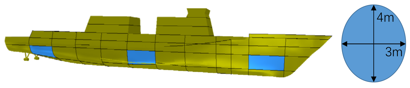
| Breach center x | 17.5 m | 50.0 m | 95.0 m |
| Breach center z | 3.90 m | 2.83 m | 3.03 m |
| Breach Diameter | 3.00 m, 4.00 m | 3.00 m, 4.00 m | 3.00 m, 4.00 m |
| Roll-Damping from Model Test | A (Fn = 0) | C (Fn = 0) | A (Fn = 0.272) | C (Fn = 0.272) |
|---|---|---|---|---|
| Intact | 0.1202 | 5.00 × 10⁻⁴ | 0.2892 | 9.00 × 10⁻⁴ |
| Aft-damaged | 0.2159 | 3.33 × 10⁻⁴ | - | - |
| Middle-damaged | 0.1919 | 3.00 × 10⁻⁴ | 0.4500 | 8.00 × 10⁻⁴ |
| Fore-damaged | 0.1237 | 5.33 × 10⁻⁴ | 0.3219 | 5.67 × 10⁻⁴ |
Disclaimer/Publisher’s Note: The statements, opinions and data contained in all publications are solely those of the individual author(s) and contributor(s) and not of MDPI and/or the editor(s). MDPI and/or the editor(s) disclaim responsibility for any injury to people or property resulting from any ideas, methods, instructions or products referred to in the content. |
© 2024 by the authors. Licensee MDPI, Basel, Switzerland. This article is an open access article distributed under the terms and conditions of the Creative Commons Attribution (CC BY) license (https://creativecommons.org/licenses/by/4.0/).
Share and Cite
Lu, J.; Zhao, Y.; Shi, C.; Yu, T.; Gu, M. A Numerical Method on Large Roll Motion in Beam Seas Under Intact and Damaged Conditions. J. Mar. Sci. Eng. 2024, 12, 2043. https://doi.org/10.3390/jmse12112043
Lu J, Zhao Y, Shi C, Yu T, Gu M. A Numerical Method on Large Roll Motion in Beam Seas Under Intact and Damaged Conditions. Journal of Marine Science and Engineering. 2024; 12(11):2043. https://doi.org/10.3390/jmse12112043
Chicago/Turabian StyleLu, Jiang, Yanjie Zhao, Chao Shi, Taijun Yu, and Min Gu. 2024. "A Numerical Method on Large Roll Motion in Beam Seas Under Intact and Damaged Conditions" Journal of Marine Science and Engineering 12, no. 11: 2043. https://doi.org/10.3390/jmse12112043
APA StyleLu, J., Zhao, Y., Shi, C., Yu, T., & Gu, M. (2024). A Numerical Method on Large Roll Motion in Beam Seas Under Intact and Damaged Conditions. Journal of Marine Science and Engineering, 12(11), 2043. https://doi.org/10.3390/jmse12112043