1. Introduction
A pipeline refers primarily to an enclosed pipe system that extends between two or more process facilities (e.g., offshore platforms, pumping/compressor stations, tank farm/storage facilities, refineries, etc.) to convey bulk volumes of fluid or fluids between those process facilities [
1,
2,
3,
4,
5]. There is demand by different oil and gas operators to utilise existing ageing offshore structures, which has led to the need for the development of new regulations [
6,
7].
Decommissioning a pipeline refers to disconnecting a pipeline from all sources of process fluid, removing process fluid from the pipeline, and leaving the pipeline in a safe state for potential repair, intervention, future re-commissioning, or permanent removal from service [
8,
9,
10,
11,
12,
13,
14,
15,
16,
17,
18,
19]. Please refer to
Appendix A for the definitions and terminologies used in the decommissioning industry. The typical reasons for decommissioning or removal from service may include the following:
The pipeline’s integrity is no longer fit for the intended service and is uneconomic to repair (i.e., corroded, damaged, etc.).
It is uneconomic to operate; an alternate transportation route/method is available.
A decline in market demand.
No immediate use; the closure of ingress or egress terminals/locations or the depletion of production facilities.
Temporary closure to carry out engineering work/repairs, etc.
Regional and international conventions, in addition to most national laws, do not address the removal of offshore pipelines. The decommissioning process is triggered by a forecast of the decline in production from the field(s) to sub-economic levels, the loss of serviceability, or damage to the upstream system such that it may not be used commercially.
The timing of the decommissioning of a facility/structure/pipeline/umbilical/cable is predominantly governed by the operator/asset and existing management plans/field development plans/pipeline management plans and production licenses. All proposed decommissioning operations, be it mothballing or decommissioning parts or the whole of the field, must be in accordance with submitted and approved management and environment plans under the current legislative framework.
It is industry best practice to outline the minimum requirements for the safe decommissioning of pipelines. There are no international guidelines that fit all decommissioning programmes, as such tailored specifications on decommissioning disused offshore pipelines have to be elaborated or adopted; as such, each pipeline should be assessed and discussed by the operators’ decommissioning team and the regulatory body within that jurisdiction to agree on the best possible methodologies to adopt.
Also, the current specifications from independent bodies like DNV enable operators to decommission pipelines under the jurisdiction of the regulatory agencies of licence-awarding countries, and all these decommissioning requirements must be developed and signed off before the commencement of the projects. The different operators have their Design and Engineering Practices where all these requirements are specified. Looking at the huge costs associated with clean-up and fines, operators and regulatory agencies ensure that the decommissioning requirements are stringent to minimise the impact of oil spills or any environmental damage due to improper decommissioning. Thus, several decommissioning programmes exist for different assets, like pipelines and offshore platforms. One recent decommissioning programme is the Brent Field’s Pipeline PLU6294 Decommissioning Programme by Shell, which could also provide more insight on developments into pipeline decommissioning.
Most regulatory regimes have no specific mandatory requirements for pipeline decommissioning or removal from service. However, other industry regulations, legislation, or international conventions may form the basis of the process applied to pipelines by regulators in considering the impact of pipeline decommissioning. Early engagement with regulators is therefore recommended to ensure the Execution Strategy is in line with their requirements. The regulatory requirements in the country in which the pipeline is situated may define the standards that apply to that pipeline.
Both DNV-STD-F101 [
20] and ISO 13623 [
21] consider the decommissioning and abandonment of petroleum pipelines and umbilicals, respectively, to some extent. For instance, DNV-STD-F101 [
20] offers only comprehensive guidelines and requirements regarding the decommissioning of pipelines. Sections 11.7.1.2 and 11.7.1.3 of the DNV standard states the following:
11.7.1.2: Pipeline abandonment shall be planned and prepared.
11.7.1.3: Pipeline abandonment evaluations shall include the following aspects:
Relevant national regulations.
The health and safety of personnel if the pipeline shall be removed.
The environment, especially pollution.
The obstruction of ship traffic.
The obstruction of fishing activities.
The impact of corrosion on other structures.
DNV-STD-F101 [
20] refers to “abandonment” only and makes no distinction between “abandonment” and “decommissioning” or “decommissioning in situ”. ISO 13623 [
21], Section 13.2.4 states, “Consideration should be given to decommissioning pipeline systems planned to be out of service for an extended period. Decommissioned pipeline systems, except when abandoned, shall be maintained. Buried or submerged, decommissioned pipelines shall be cathodically protected unless abandoned”.
Umbilicals can require several unique requirements when decommissioning. They are generally considered separate from the pipelines or subsea systems and need an independent strategy for decommissioning. Umbilicals are designed according to ISO 13628-5 [
22]. There is also some association with the standards and decommissioning requirements of the control systems, as discussed in Section 7.3 of ISO 13628-5 [
22].
ISO 13628-5 [
22] has been applied to design and install umbilicals. There are no direct guidelines for any requirements or associated activities for decommissioning umbilicals. The standard requires that the umbilical and its constituent components be capable of withstanding all design loads and load combinations and of performing their function for the specified design life (Section 4.1. (a) of the ISO 13628-5 [
22]). They should also be capable of being recovered and reinstalled, as defined in the manufacturer’s written specification (Section 4.1.1 (h) of the ISO 13628-5 [
22]). Furthermore, contingencies should be considered through risk assessment to study foreseeable occurrences, including common mode failures, and to produce suitable procedures. The decision to implement all actions in connection with contingency procedures is the responsibility of the authority designated within the guidelines (Section 15.22 of the ISO 13628-5 [
22]). Moreover, Annex A in Section 2.8 of the ISO 13628-5 [
22], states that the purchaser should specify any requirements for the recoverability and reusability of the umbilical within its service life.
This paper aims to identify the high-level requirements and provide a road map for personnel who may become involved in decommissioning a subsea pipeline system and an umbilical/cable. The information in this paper gives the preliminary requirements to decommission the subsea pipeline system safely, environmentally, and within the appropriate legal requirements. Furthermore, this article provides case studies for the decommissioning of unpiggable pipelines.
2. Input Data for Pre-Project Activities
2.1. Historical Record and Description of the Installations
Such data typically include the following:
Detailed descriptions and plans of the facilities and the field(s), including relevant parts of the design documentation, weight reports, process descriptions, well coordinates, buildings, platforms, access paths, drainage systems, waste disposal zones and sludge pits for onshore sites, overland/buried pipes, etc.
Hazardous and non-hazardous material inventories, to be collected through a survey if necessary.
Seabed survey data, including information on drill cutting piles, etc.
The architecture of the wells (vertical section).
Historical records and reports on past activity, including Well well Records records from the well production period (e.g., successive well completions, servicing, annulus pressure anomalies, corrosion, deposits, etc.).
Lists of the products presented on the site and their characteristics.
Accidentology (nature of the pollutant, quantity released, types of media affected, area covered, and actions engaged).
Archives, photographs, etc.
2.2. Environmental and Socio-Economic Data
Such data typically include the following:
General maps, showing the site’s position within its physical and socioeconomic environment.
Descriptions of the environment.
Hydro geological studies (locations of water tables).
Initial conditions of the environment prior to operations (baseline state).
Initial socio-economic conditions (land occupation and social and economic activities).
Information on potential sources of contamination and site impacts.
Other information for consideration, including the sensitivity of the site (water catchment, vulnerability of the water tables, and damp zones) and safety around the site.
To collate all that information, the following available site environmental studies and reports are used:
The initial state of the site before production operations, called the Environmental and Social Baseline Study (ESBS).
Environmental and Social Impact Assessment (ESIA).
Environment reviews.
Risk studies (Simplified and Detailed Risk Assessment).
Results of survey studies and surveillance undertaken as part of environmental monitoring.
A full environmental diagnosis of the site may have to be undertaken in case of a lack of adequate environmental monitoring during the production phase.
2.3. Regulatory Constraints
Regulatory requirements (international, national, local, and professional references) must be determined to establish the work programme’s decontamination objectives and choose the appropriate treatment to remediate the contaminated environments. It is critical to continuously monitor the evolution of applicable obligations (including local regulations and contractual requirements that may evolve rapidly), with particular attention on the following:
International laws, guidelines, and conventions (e.g., UN, IMO, etc.).
Regional conventions and protocols (e.g., Australia, Kuwait, etc.).
National laws (e.g., petroleum, maritime, trade, industry, environmental, interior, etc.).
Industry guidelines (e.g., Oil and Gas Producers Association (OGP) guidelines).
2.4. Construction, Maintenance, and Integrity Management
Construction, maintenance, and inspection records should be reviewed to determine the physical condition of the pipeline. The integrity management history of the pipeline should be reviewed to determine the current status of the pipeline’s integrity before decommissioning.
In particular, if a recent ILI (In-line Inspection) tool is run, then much data can be corroborated or derived from the record of the ILI. Typically, the following information is useful in planning decommissioning activities:
Minimum pipe wall thickness.
Bend geometry.
The presence and locations of dents, cracks, ovalities, gouges, and corrosion (refer to
Appendix C for more details regarding the corrosion associated with carbon steel pipes).
The presence and locations of metallic features, e.g., valves, doublers, branches, and other appurtenances.
The most recent successful pressure test duration, test pressure, and test medium.
The locations of any free spans or soil or seabed erosion that could lead to future free spanning or pipe exposure.
Areas requiring trenching or burial for long-term stability.
Any other information pertaining to the maintenance history of the pipeline is useful in assessing the pipeline’s integrity status.
2.5. Others
Such data typically include the following:
Relevant production license information, including conditions, clauses on decommissioning, expiry, etc.
Descriptions of relevant legal aspects, termination of ownership, possible indefinite liabilities, etc.
Relevant financial and fiscal aspects.
Preliminary Risk Management Plans.
Residual Value Reports.
Follow-ups of previous cessation-related actions indicated in pre-development environmental impact assessments.
Records of all contacts and consultations with stakeholders (authorities, communities, contractors, etc.) from preliminary discussions to formal approval.
3. Applicable Regulations
There are several relevant regional and international conventions/protocols [
23,
24,
25,
26,
27,
28,
29,
30,
31,
32,
33,
34,
35,
36,
37,
38,
39,
40,
41,
42,
43]. They are applicable to decommissioning and abandonment. The regulatory requirements in the country in which the pipeline/umbilical/cable is situated may define the standards that apply to that pipeline/umbilical/cable that is decommissioned.
4. Project Execution and Government/Regulatory Approvals
4.1. Planning
Decommissioning activities require planning prior to commencing. The roles and responsibilities should be clearly identified, and a decommissioning programme should be established to manage and support the planning process and approval requirements. The decommissioning process should take into consideration the appropriate state, national, and international legislation, guidelines, and standards, as outlined in
Section 4. The following sections further discuss the various planning and process requirements.
4.2. Management and Responsibilities
A specified decommissioning project team is responsible for preparing a Decommissioning and Closure Plan and for developing a decommissioning programme. The project team interfaces with the operations team to ensure all activities are considered. The selection process is like the selection of a brownfield concept, concluding with the business case, cost, and schedule forecast and an outline plan for the selected decommissioning concept. In the subsequent development phase, responsibility is transitioned from operations to the project team responsible for the decommissioning activities. Consideration is given when selling an asset to a third party, such that the purchaser takes reasonable care to dismantle/recycle/dispose of the asset.
4.3. Decommissioning Process
The decommissioning process is typically prompted by a forecasted decline in production to sub-economic levels or loss of serviceability. The economic assessment for end-of-field-life justification is detailed in the business case of the facility to be decommissioned. The criteria for stopping production depend on oil/gas prices and operating costs. The operating costs used for such a decision need to be the actual incremental costs of running a facility (i.e., excluding, for example, overheads which would continue once the facility is decommissioned). The cut-off point, in principle, is the point where incremental OPEX (excluding overheads not directly related to the facility) is greater than the value of incremental production. Decommissioning projects is typically split into four distinct phases:
The decision to initiate (ASSESS).
The concept selection phase (SELECT).
Project planning and preparation (DEVELOP).
Project implementation (EXECUTE).
The key project focus decisions, deliverables, and government approval submissions required are summarised in
Table 1. Details for each of the phases are provided below.
4.3.1. Assess Phase
In the Assess Phase, reservoir and resource management, operational plans, and field economic and technical status are reviewed to decide that planning for decommissioning must commence. Planning for decommissioning must start well ahead of forecasting the cessation of decommissioning activities to ensure all required approvals and procedures are in place. This could be five years in advance for large hydrocarbon fields with numerous facilities. Planning to decommission small pipelines and facilities should commence approximately three years in advance.
The assessment phase comprises but is not limited to the following steps:
Define the scope of the decommissioning project, e.g., what falls under the asset holder/operator’s responsibility and what falls under contractual agreements and the project execution plan;
Identify (the need for) dedicated resources and define responsibilities;
Identify the need for a Decommissioning Steering Committee;
Identify what commitments have been made to the government during obtaining the production license, the field development plan, environmental approval documentation (referral, Environment Plans, etc.), the safety case, etc.;
Identify decommissioning options/strategies;
Initiate the HSE assurance process;
Initiate the government approval process and identify which approvals are required as part of a strategy;
Identify stakeholders and develop a stakeholder consultation strategy consistent with the HSE assurance process.
The submission includes reservoir data as required to relinquish the permit for a field. This consists of historical data, PVT analyses, reserves left in place, and an overall estimate of the resources produced. The assessment and selection of preferred decommissioning options require an integrated multidisciplinary engineering team, including representatives from the drilling, subsea, HSE, and offshore (and onshore) operations support teams. Issues to be taken into consideration are shown in
Table 2:
4.3.2. Select Phase
In the Select Phase, alternative decommissioning options are evaluated, and the preferred option is selected and described. The decommissioning options are based on commitments set out in the following documentation:
Decommissioning options are based on commitments made in any facility safety case, management plans, environmental plans, conditions under governmental approvals, or other relevant documents, such as field development plans. As part of the approval process, it is necessary to present an initial decommissioning philosophy. This philosophy must include options considered for well killing and abandonment, the removal of subsurface equipment, equipment to be recovered from the seabed or left in situ, the identification of any environmental and safety issues, etc.
A preliminary project execution plan is required at the outset, and this defines the areas of regulatory approval that must be satisfied to allow the project to proceed. It is essential to provide as much information as possible as part of the initial approval application to prevent delays later in a project associated with late approvals. Late approvals can have a significant impact on the viability of a project.
The programme may consider a phased decommissioning plan; however, the relevant designated authority should be consulted well in advance. An environmental plan should be submitted for approval before any operations commencing. The requirements include confirmation that the system’s integrity will be maintained or that any deterioration will not compromise the safety or practicability of subsequent decommissioning operations. In all cases, all respective authorities and legislative bodies should be consulted throughout the selection phase. The close-out criteria for the decommissioning scope of work must be discussed and agreed upon with the regulator before progressing further to the Develop Phase.
4.3.3. Develop Phase
The Develop Phase involves project planning and preparation. During this phase, the project transitions from the development division to the project division, and by its conclusion, a dedicated project team is formed under a decommissioning project manager. This project team base can be either formed by the operator/asset holder or may be completed within a contracting office. The project team usually comprises an integrated multidisciplinary engineering team, including representatives from the drilling, subsea, assurance, HSE, and onshore and offshore operations support teams. The decommissioning team is responsible for the design, engineering, preparation, and final implementation of the overall project work scope. After consultations, it should be workable for the operator/asset holder and the government to accept a final draft of the decommissioning campaign. Formal submission of the programme is then lodged.
Before the submission of a decommissioning application to the government, the operator/asset holder should ensure that the application follows the assurance processes through a review by a suitably qualified team, independent of the project team or through peer review. The review team has knowledge and expertise in the following disciplines:
Government approvals and international legislation relating to decommissioning pipelines and facilities.
Environmental engineering (expertise in environmental regulations, environmental impact assessments, and post-decommissioning monitoring requirements).
HSE engineering (expertise in safety assurance and risk assessment).
Pipeline engineering (expertise in pipeline decommissioning, pipeline stability, and inspection and condition assessment).
Process engineering (expertise in decommissioning aspects of topside equipment and pipelines, including the removal of hydrocarbons from contaminated equipment/pipelines).
Construction engineering (expertise in the practical aspects of executing decommissioning work in the field).
Subsea engineering (expertise in decommissioning aspects of wellheads, flowlines, and control umbilicals).
4.3.4. Execute Phase
The final stage of the project involves implementation. During this phase, the field goes through final shutdown preparations before the cessation of production. This is followed by concurrent decommissioning activities for the subsurface, subsea, and topsides, leading to the final demobilisation of the facilities, vessels, structures, or pipelines from field and site surveys.
A revision of the facility safety case/pipeline management plan, diving safety case (if required), and environment plan must be submitted at least three months before field decommissioning for approval by the relevant authorities. The revised approved documents are implemented for the facility or for the pipeline/diving operations as part of the final (field) shutdown. The documents should cover all shutdown and decommissioning activities within the field. Any revisions to the programme with a significant change to HSE are subject to government approval per legislation and regulations.
After the Execute Phase, the operator/asset holder is obliged to notify the relevant authorities that the agreed campaign has been executed. A summary of a typical decommissioning programme can be found in
Table 1.
4.4. Deferral and Phased Decommissioning
Each decommissioning scenario has several unique steps to consider depending on the selected method or techniques. The systems can be entirely removed, partially removed, or left in situ. A phased decommissioning process may be required where decommissioning activities are complex and/or multiple decommissioning methods are necessary. This may require several phases or stages to carry out and complete the activities.
Figure 1 shows the possible solutions for decommissioning. The following definitions also apply:
Re-use: To keep in situ and conditioned for future use.
Recycle: To condition and remove for reclaiming for other purposes.
Disposal: Conditioning and removing to be discarded.
Phased: To have sections isolated, conditioned, and removed in stages to be discarded.
The implementation and execution of decommissioning activities are often split into two stages. Stage 1 of the decommissioning process typically involves the conditioning of the system. This incorporates several proprietary steps to safely isolate, flush, and preserve the system. Stage 2 of the process involves the completion of the decommissioning activities to remove equipment and/or leave it in situ, as determined by the selection process.
Figure 2 shows the processes through the two stages.
System integrity should be maintained until all decommissioning activities have been completed to limit any damage or degradation that may obstruct the decommissioning process (corrosion, marine growth, etc.). Preservation of the system should be achieved through isolating specific item(s) from the system, flushing all hydrocarbons and hazardous substances, and flooding with an inert medium (typically treated water) until decommissioning activities are commenced. Additional treatments include biocide with O2 scavengers and corrosion inhibitors, which may also be used to reduce undue degradation of the systems. Periodic monitoring, condition assessments, and maintenance should be continued where necessary.
5. Decommissioning/Abandonment Options for Pipelines
The main issues to be considered in deciding which option to choose are as follows:
Legal requirements, including compliance with license conditions.
Operator/asset holder commitments.
Environmental impacts.
Stakeholder impacts (fishing, navigation, and shipping).
Economic considerations.
Safety.
Liability.
Technical feasibility.
Reputation.
It is impossible to determine the legislative requirements that will be in place at the end of a field life, and there are no international regulations to date that specifically dictate how to decommission pipelines. Current regulations, however, require decommissioning activities to be included in the pipeline management plan and safety management case, and prior to engaging in such activities, written approval must be submitted and obtained from the DA. In addition, the conservation and protection of natural resources should be maintained, and any damage to the seabed or subsoil should be repaired to the satisfaction of the designated authority. The options currently available for pipeline decommissioning include the following:
Re-classification;
Disposal in situ;
Removal.
5.1. Re-Classification
Depending on the end-of-life conditions of pipelines, it may be possible to re-certify them for operation beyond their design life or to reclassify them for alternative use. All proposals for the reclassification and life extension of pipelines require detailed fitness for purpose assessments. Internal and external inspections, testing, and/or calculations should be performed to the respective standards and regulations. This should include comprehensive surveys and measurements of anode potentials, as additional interventions may be required, such as pipeline stabilisation or the replacement of anodes and other consumables.
5.2. Disposal In Situ
The simplest and most cost-effective decommissioning option is to thoroughly clean the pipeline of all hydrocarbons and other potentially harmful chemical residues, disconnect it from all other installations, and leave it in situ, flooded with treated water or a similar inert medium.
For buried subsea pipelines, provided that the ends are also covered to protect from snagging trawl gear, the best environmental solution is to leave the pipelines in place to decay over time. Small bore pipelines are trenched along the length of the pipeline route and up to the escarpment on Jansz pipelines; however, some level of scouring or upheaval may occur over the life of the pipelines. Production flowlines and infield pipelines are laid on the seabed, although self-burial may occur over the life of the pipelines. Subject to the pipeline’s status/condition and regulatory approval, it may be necessary to bury sections of the pipeline in order to leave it in a safe and environmentally acceptable condition.
The decommissioning process ensures that the pipeline does not become a potential source of contamination and does not act as a conduit for water. Sectioning of the pipeline may be required to eliminate the possibility of groundwater transfer/flooding. Consideration is made to ensure the pipeline does not become a hazard if exposed to subsequent streambed scouring and/or surface erosion.
Natural vegetation growth should be encouraged along the pipeline land easement, but induced access management controls should be left in place to provide access to monitoring and other post-decommissioning activities.
All pipelines that are left in situ require continued monitoring and maintenance, where necessary, to reduce any risk to the safety and environment of the surrounding area. See
Section 7 for further details on the post-decommissioning requirements.
5.3. Removal
When disposal in situ is not feasible, pipelines are removed for disposal or recycling. Removal is likely to be a cost- and energy-intensive process, taking months to complete. All pipelines must be isolated and flushed to ensure the items can be retrieved and disposed of or recycled safely. Tests are required to check for the presence of radioactive material (NORM), which has been known to collect in pipelines from wells.
There are various methods available for the removal of subsea pipelines. These consist of reverse installation processes (i.e., S-lay, reeling, and towing) along with other methods specific to removal, such as cutting sections of the pipeline, recovering these sections, and placing them on a barge. Once the flowline/pipeline is recovered, it can be transported to a suitable base for recycling, reconditioning, or disposal. The feasibility of this operation depends greatly on the final condition of the pipeline with respect to corrosion, burial status, and the general stability of the pipeline. The removal of buried pipelines requires extensive excavation and may have more of an impact on the environment than that of being left in situ.
5.4. Umbilicals and Flying Leads
Similar to pipelines, no regulations currently dictate how to decommission umbilicals. Detailed plans must be developed before decommissioning activities commence and are submitted to the designated authority for approval. For all scenarios, decommissioning procedures include the thorough flushing of the umbilical to remove all traces of chemicals and isolating and disconnecting all electrical lines.
Subsea umbilicals are predominantly buried. Umbilicals may be left on the seabed in an exposed, trenched, or buried state, subject to detailed assessments of environmental and safety impact. This is the simplest and most cost-effective option. It may be necessary to bury sections of the umbilical to leave it in a safe and environmentally acceptable condition. All cut lengths, infield cables, flying leads, or associated items should be removed from the seabed and disposed of appropriately.
When umbilicals are deemed a significant risk to the environment and/or to the safety of other marine activities, umbilicals may be removed through several methods, including removing them through a reverse reel technique or by cutting and retrieving the pieces to place them on a barge. Removing buried sections of umbilicals may lead to a greater disturbance to the environment than being left in situ.
One recent decommissioning programme that involved an umbilical was the Brent Field’s Pipeline PLU6294 Decommissioning Programme by Shell [
44], which was approved for decommissioning in 2020, and the process of undertaking the decommissioning started in 2023 Q3. The transfer of the ownership of the control umbilical from the Brent Alpha splitter box to NLGP SSIV occurred following the acceptance of the Brent Field Pipelines Decommissioning Programme [
45] in 2020. The entities Shell U.K. Limited and Esso Exploration and Production UK Limited are now the owners of this control umbilical. Consequently, a section 29 of the UK petroleum Act (a “Section 29 Notice”) was recently issued, designating the umbilical with the identification number PLU6294. It is noteworthy to add that PLU6294 can be understood as a logical extension of the control umbilical PLU4562, which served as the means of connection between the Brent Alpha jacket and the Brent Alpha splitter box. At the point of division, the control umbilical at the splitter box is separated into two segments. The first segment, known as PLU4562, is connected to the Western Leg Gas Pipeline (WLGP) SSIV in close proximity to the Alpha jacket. The second segment, referred to as PLU6294, links the Brent Alpha splitter box to NLGP SSIV situated along pipeline PL164. The PLU6294 route is mostly characterised by being trenched and buried, with certain sections put on the surface. This is particularly evident in the vicinity of NLGP SSIV and at the crossing point with PL49, where the pipeline is protected by a mattress. The intersections located at PL4104 and PL4492 are characterised by the presence of rock material that was strategically placed over excavated and concealed portions of PLU6294, which was buried inside the trenches [
44,
45].
6. Post-Decommissioning Requirements
Upon the completion of decommissioning, the operator is required to implement any arrangements that have been agreed upon with the government in relation to the monitoring, maintenance, and management of the decommissioned site and any remains of pipelines and subsea equipment. This scope is agreed upon with the government during the Select and Develop activities to ensure conformity before implementing the plan.
6.1. Monitoring
All pipelines that are left in situ require continued monitoring and maintenance, where necessary, to reduce any risk to the safety and environment of the surrounding area.
As part of the agreed decommissioning assessment and consultation procedures, any facilities left in place may be subject to a monitoring programme at appropriate intervals. A suitable monitoring programme is devised in agreement with the regulator. Details of the monitoring programme are included in the decommissioning and closure management plan and the decommissioning programme submitted to the relevant government agencies.
The duration and types of monitoring depend on the circumstances and, if necessary, should be adapted with time. Inspection reports may be required to be submitted to the relevant designated authority, together with any proposals for maintenance or remedial work that may be required.
Following removal from service, the necessity for pipeline maintenance is eliminated for practicality and cost-effectiveness.
The following measures may be taken to eliminate the necessity for pipeline maintenance:
Post-decommissioning monitoring and maintenance preserve the condition and integrity of the pipeline in order to prevent the pipeline from becoming a hazard to third parties and the environment and to allow the pipeline to be re-commissioned or removed from service from a known condition at some time in the future, even if re-commissioning at the time of decommissioning is not apparently viable or likely.
Following decommissioning and filling with either nitrogen or water, the pipeline’s integrity should be monitored.
Measures that are required to prevent external corrosion in a decommissioned pipeline should be the same as those for an operational pipeline.
In cases where the pipeline is discontinuous because of the removal of in-line equipment or sections/pieces of pipe from the pipeline, special measures should be instituted, given the resultant discontinuity of the pipeline.
Specialist technical advice should be sought to define the post-decommissioning CP (cathodic protection) requirements during the planning and design of the decommissioning process.
If ongoing CP is required, it should be monitored and maintained in the same manner as that when the pipeline was operational, including transformer/rectifiers and electrical power supplies.
If there is any history of spillage of conveyed fluid from the pipeline, monitoring of the groundwater in the pipeline corridor is carried out to monitor for any ongoing liabilities. Such requirements are highlighted in the environmental and social impact assessment after consultation with the appropriate authorities.
6.2. Sampling
Post-decommissioning environmental seabed sampling may be required to monitor the level of any residual hydrocarbons, heavy metals, and other contaminants in sediment, flora, and fauna. There is a greater need to survey more sensitive shallow water areas closer to shore due to the higher population of flora and fauna. Deepwater areas from the escarpment require a less rigorous sampling survey.
Monitoring programmes are used to ensure that sampling and analysis are completed correctly in conjunction with the relevant designated authority as required. Details of the agreed survey/sampling strategy are included in the decommissioning and closure management plan and the decommissioning programme.
6.3. Debris Clearance
Upon completion of each decommissioning and abandonment operation, applicable surveys are expected to be carried out to identify and recover any debris on the seabed that has arisen from the decommissioning operation. The most likely situation for this to be a requirement is when the area will be used by other sea users and remaining debris could provide a safety hazard, or when sensitive environments are located close to the decommissioning areas and impacts upon these areas could be reasonably expected.
The survey area depends on a case-by-case situation. The UK DBERR Guidelines [
42] state that the minimum required survey area has a radius of 100 m on either side of the decommissioning pipeline over its entire length. The US Minerals Management Service (MMS) decommissioning regulations require trawling in a circular radius between 200 and 400 m around the entire length of the pipeline, or side-scan sonar, diving, and remotely operated vehicle surveys over a grid of 200 m to 400 m centred around the entire length of the pipeline, to verify there are no obstacles left on the seabed that could impede other users of the sea.
Following the removal of debris, seabed clearance verification might be necessary. Options for verification include trawling, side-scan sonar, remotely operated vehicle videos, and diving, where appropriate. The suitability of verification surveys is considered on a case-by-case basis and depends upon the relevant designated authority requirements, safety considerations, the extent of any remaining cutting piles, and any other relevant circumstances.
7. Case Study 1
In this case study, as highlighted in
Figure 3, one operator proposed to relocate the processing complex to a greenfield location away from the existing production station, to replace all existing flowlines, and to facilitate a smooth switchover from the old offshore production station to the new offshore production station at the greenfield location.
This section presents a sample methodology for decommissioning unpiggable pipelines and umbilicals. Oil pipelines transport oil from the wellhead jacket (WHJ) to the production station and vice versa for the gas lift pipeline and umbilical. The steps required to decommission this pipeline are summarised in the following sections.
7.1. Project Management
A specialist team is responsible for delivering the safe, efficient, and environmentally sound decommissioning/abandonment of pipelines, and it should be recognised that the required skill sets for this phase of the asset life cycle are very different from the asset’s commissioning and operational phases. Decommissioning is not commissioning in reverse.
7.2. Facility and Pipeline Permanent Isolation and Cleaning
7.2.1. Topsides
The mechanical isolation of platform systems is implemented by operations, followed by cleaning and any physical isolations that may be required to make the systems safe for separation scopes, outlined under topside preparation.
Activities are prepared for in the proposed decommissioning methodologies for the operations team to review. Execution can include draining, flushing, purging, and venting scopes to provide auditable records of the platform status and its safe condition with respect to health and safety hazards.
Permanent, positive isolation of energy sources, physical air gaps, vents, and drains is then implemented to prevent the re-charging of all systems, followed by bulk draining liquids from all tanks and vessels. The scope execution is grouped, considering SIMOPS (simultaneous operations) constraints.
7.2.2. Cleaning Operations
As systems are drained, flushed, purged, and vented (and air-gapped from any live systems), cleanliness certificates are issued to demonstrate the end state of the vessel, pipework, or other systems. It is recommended to append photographs, particularly of internals or tanks/vessels, as this helps quickly identify what residues may be left, which must be dealt with at onshore dismantling and waste disposal yards. The cleaning operations stop when the oil content in the water inside the pipeline is less than 15 ppm and when the cleaning run with pigs has stopped.
7.2.3. Control of the Decommissioned Status
As systems become decommissioned, their status can be captured by ‘blue lining’ controlled P&IDs to clearly show what can now be considered ‘idle iron’. The blue-line P&IDs can then be used to communicate the status of systems and allow system components to be removed from the maintenance system, which becomes essential in terms of reducing post-switchover OPEX, mainly if there is a cold-stack or idle phase.
7.2.4. Subsea Pipeline Cleaning
The intent of the cleaning scope is to remove transportable contaminants, such as contaminated fluids, oil, water, gas, soft superficial wax, and mobile sand. Pipelines require having their hydrocarbon inventories removed down to a level of <15 ppm of oil in water, and once clean, they are abandoned in situ. Flushing with raw filtered seawater is the primary method for most pipelines, but chemical cleaning (chemical slugs) with gel pigs and mechanical pigs may be used on more extensive outside diameter lines >8″.
Most of pipelines have a small internal diameter and are shorter in length, and a high-velocity water flush is an effective way of removing hydrocarbon inventories. For some larger infield pipelines (>8″), positive displacement of the pipeline inventory from the flushing water is required, and gel pigs are used to perform this function.
As infield pipelines have not been pigged during operation at any time, smaller bore lines, e.g., 4″ and 6″, should only be flushed with water as a base case due to the risk of blockages/stuck pigs and the failure to displace the inventory. The other option is to utilise a slug of wax dispersant to clean the pipe, followed by 50 μ filtered seawater, until their hydrocarbon inventories are removed to a level of <15 ppm of oil in water.
7.2.5. Pipeline Loops
Most WHJs, for this example, are small, with minimal space or facilities available for the operation of a pumping spread and associated equipment that would be required to flush the lines. Each WHJ, however, has a gas lift pipeline from the main complex facility and at least one production return line. Wood proposed that these are formed into pipeline loops to allow for the flushing/pigging of the lines. This means that the pumping equipment required to perform flushing is only rigged up once on the main complex facility instead of having to rig up/move the equipment and personnel required for each WHJ. The other benefit is that a single pumping operation flushes two, three, and, in some cases, four pipelines simultaneously, reducing the scheduled activity and associated costs. A schematic of the proposed pipeline flushing loops is presented in
Figure 4,
Figure 5,
Figure 6,
Figure 7,
Figure 8,
Figure 9 and
Figure 10.
Water is pumped from the old main complex facility via the gas lift subsea pipeline to the WHJ, where a temporary crossover at the WHJ is used to link a port on the blind flange (installed following the switchover to the new offshore production station) to a port on the blind flange installed on the return production line (see
Figure 4,
Figure 5,
Figure 6,
Figure 7,
Figure 8,
Figure 9 and
Figure 10 for further details).
Back pressures for the combined loops are evaluated at the proposed 1 m3/min and are well within the pressure capabilities of the pipeline’s operation. Due to integrity concerns, the flushing/pigging operation must not exceed the last operating pressure of the pipeline, even under a stuck pig scenario.
It is important to indicate that the friction losses through a 2″ 1502 hose should be considered during engineering. The 2″ 1502 is a heavy wall hose with around 1.5″ ID. This can increase the flushing pressure. Another alternative to hose 1502 is the black eagle hose.
7.2.6. Fluid Return
Fluids from flushing loops are returned to the old offshore production station for processing, where there are several options for processing depending on the status of the equipment.
Routing to the test separator.
Routing through temporary pipework directly.
Routing to tanks on a barge moored alongside the main complex.
7.2.7. Pipeline Flushing
A value of 1 m3/min gives a flushing velocity of approximately 3 m/s in the 4″ lines and approximately 1.5 m/s in the 6″ lines. This is regarded as sufficient to create turbulent flow and effectively flush these pipelines. A base case of a three-line volume flush should be performed on these lines, but as most of the 4″ and 6″ lines feed into the larger lines to create loops, this means that, in most cases, more than three-line volumes are introduced.
7.2.8. Gel Pigs
A positive interface of gel pigs is required for 8″ and 10″ lines and is introduced into the pipelines at the connections that are installed as per
Section 7.2.5. The use of gel pigs could be beneficial both for the effectiveness of the pigging operation but also for the removal of the pig from the test separator, temporary collection drum, or receipt.
The gel pig can be installed into the pipeline end prior to the flange being connected. This can be performed either by a canister with ports to allow for the pig to be pumped in or a canister with a screw/plunger arrangement. The option exists for two or more gel pigs to be introduced into the pipeline to be decommissioned at this time, should this be deemed necessary following detailed engineering. A small pumping spread (2″ diaphragm pumps or similar) could be used to pump the first gel pig a short distance into the line, followed by approximately 100 linear m of seawater before a second (and third) gel pig is introduced. Engineering is required for the more giant 12″ and 16″ lines to ensure that the gel pigs are suitable, with either several gel pigs or the introduction of mechanical pigs to be considered. Pigs are evaluated for their ability to pass the choke and check valves if required. Additional note: Gel trials can be performed (with cost implications, but they give good data and reassurances)
7.2.9. Removal of Hydrocarbon Fluids with Mechanical Pigs
Some pipelines are cleaned to a level of ≤30 ppm of oil in water by means of displacement pigging. This is the most efficient way to remove hydrocarbon fluids from pipelines. Pigs with good sealing capabilities are chosen to remove hydrocarbons, but this method is still effective even if the seals are bypassed to a certain degree.
Table 3 shows conservative case figures assuming a 100% oil-filled system.
The pigs should be of a bespoke design, specifically for the case study pipelines to negotiate unbarred TEEs and the 1.5D bends present in the system, coupled with 360° steel brushes and strong earth magnets, which ensure the pipeline is left with minimal debris for abandonment.
Filtered/treated seawater is supplied from a pumping spread on the old offshore production station, and the same is used for the flushing/pigging of infield loops. A four-pig batch separated pig train de-contaminates the pipeline to <30 ppm of hydrocarbons based on a low-percentage bypass, achievable with conventional high-seal pigs. Each pig is separated with a continuous slug of filtered/treated seawater (approximately 500 linear m) until the next pig can be launched. Following the final pig in the train being run, a continuous flow is provided to facilitate the completion of the decommissioning (see
Figure 11).
7.2.10. Sampling
For the pipelines, the return is sampled during flushing/pigging operations on the return line at the old offshore production station. If fluid received at the old offshore production station is below 30 ppm, most likely, all pipelines in the loop are at or below this level. Samples are taken, recorded, and signed off for the pigging fluid following each pig until the ≤30 ppm level is achieved.
7.2.11. Contingency
If 30 ppm is not achieved in the infield pipelines from water flushing/pigging alone with the proposed three-line volumes, then flushing continues to five-line volumes. If there is no significant reduction in the oil in the water samples taken between the three-, four-, and five-line volume samples, then flushing is ceased, and gel pigs are then introduced into each of the pipeline loop sections. Flushing/pigging continues until the required cleanliness is achieved.
7.2.12. Umbilical Cleaning
Chemical umbilical cores are displaced with a suitable compatible fluid to ensure the chemical is removed. The chemical can be routed into the product line, i.e., the corrosion inhibitor, at the typical rates until the flushing fluid arrives at the injection point, and it can then be routed to a temporary vessel until three flushes are achieved. Alternatively, a fast flush of the entire core can be completed after switching to the new facilities.
Air and hydraulics are stabilised, and it is assumed that the hydraulic fluids, where present, are suitable for sea discharge and do not need to be flushed.
Electrical cores can be cut after isolation and earthing at the source.
Communication cores: Fibre optics and those which use an electrical carrier signal can be severed after permanent isolation is confirmed.
8. Case Study 2
The field is a mature oil field located in shallow water with a maximum water depth of 40 m. This field has been producing oil and associated gas for over 50 years, with production rates continuously declining. The existing facilities have already exceeded their design life, and significant quantities of oil and gas reserves remain to be recovered from the reservoirs. However, such potential cannot be stabilised through the existing facilities alone due to ageing and/or specific process requirements, and therefore, the owner of the field is undertaking an extension of its field life through the redevelopment of assets. The owner of the field aims to extend the life of these two fields by 30 years by maximizing the use of existing facilities to the extent possible and by installing new facilities.
This case study covers the decommissioning and abandonment (D&A) of the subsea infrastructure for the X field. This case study covers the entire process which will be taken to decommission each piece of the subsea pipeline/umbilical/cable/subsea structure.
8.1. Subsea Screening Summary
A preliminary screening methodology was adopted at this stage of the process. The objective of this preliminary screening was to identify all possible options for each of the groups and to ‘screen out’ unrealistic options. The options were screened out based on technical difficulties, safety concerns, and economic risk to the operator.
The outcome of the screening assessment is presented in
Table 4.
8.1.1. Umbilicals, Cables, and Flatpacks
This section covers the asset listing for the following items:
The services vary from platform to platform but may include power, fibre optics, instrument air, glycol, or chemical inhibitors, and they may or may not terminate within a topside umbilical termination unit (TUTU). The umbilical or flatpack risers are strapped to the steel riser along with a bend restrictor at the base, and some umbilicals are within J-tubes. They are then either routed with spools or join the main pipeline and are strapped in place (
Figure 12,
Figure 13 and
Figure 14) approximately every 4 m.
8.1.2. Risers and J-Tubes
The base case is that the risers are fully removed for weight-shedding purposes if the platform is remaining. For cases in which the topside modules and jacket are being fully removed, the riser can be cut at a suitable location above the seabed and left for jacket removal.
8.1.3. Subsea Structures (Piping, Wye, Valves, and Protection Structures)
Figure 15 shows typical subsea wye skid flanged connections installed with a ‘protecting cage’ over the top.
8.1.4. Mattresses, Grout Bags, and Support Structures
There is a variety of subsea protection structures, including grout mattresses, concrete mattresses, and grout bags. During the removal process, the condition of the mattress is assessed. As they have been subsea for 50 years, the integrity may be compromised, and if it becomes clear that they are going to break apart into pieces, then a decision will be made on whether to continue recovery. Grout mattresses are classed as “under” pipelines, and therefore, it is proposed that these are left in place unless they are under the 20 m sections of pipeline, planned to be removed. An example of a stabilisation mattress under a pipeline can be seen in
Figure 16.
8.2. Removal and Disposal Methodology
8.2.1. Isolation and Hydrocarbon Freeing
Pipelines should be cleaned to a level of ≤30 ppm of oil in water and flooded with seawater. Umbilicals should be flushed and replaced with water.
8.2.2. Vessel and Equipment Requirements
The decommissioning of subsea facilities should be undertaken by appropriate vessel types, as follows:
Diving support vessels for ROV deployment, diving activities, lifting, and storage on the back deck.
Cargo barges and/or supply vessels for the storage and transportation of recovered material.
Survey vessels for pre- and post-decommissioning surveys (if not item 1).
A typical listing of equipment/provisions may be as follows:
Hydraulic shears.
Applicable lifting rigging arrangements for subsea operations.
Carousel or powered reel (optional) for umbilicals.
Workbaskets or containers for umbilical/cable/pipeline recovery.
Protection mattresses.
SIMOPs need to be reviewed depending on the decommissioning work phase, whether prior to any greenfield operations or post greenfield installation.
8.2.3. Pre-Survey
It is assumed that a full pre-survey of all the relevant pipelines and assets to be decommissioned will be undertaken to provide baseline data and identify any anomalies for the proposed works.
8.3. Pipeline Removal Methodology (Groups 1 to 3)
The pipeline removal methodology involves performing two cuts for every 20 m section via hydraulic shears (
Figure 17), recovering them, and bringing them back to the DSV for onshore disposal. Hydraulic shears are suitable for making multiple cuts without recovery to the deck for replacement or consumables. Depending on the quantity of material to be recovered, it may be more cost-efficient to transfer cut sections to a supply vessel, which may make multiple trips to and from shore.
If a pipeline being decommissioned crosses or is crossed by another operating pipeline, the section of the pipeline at the crossing is left in situ until the operating pipeline is also decommissioned. A high-level schematic is included within
Appendix B covering the approximate sequence of operations, as follows:
Mobilise the vessel along with relevant diving and equipment spreads.
Transit to the work site.
Confirm isolations in place and the pipeline’s as-left status.
Deploy the ROV for the survey of the pipeline/location.
Deploy divers to assist with rigging arrangements to allow the recovery of the sections to either the vessel’s back deck or a subsea container.
Deploy a cutting tool and perform a cut at each end (20 m sections).
Recover the cut section and bring it to the vessel’s back deck and then transfer it to the supply vessel (optional).
Recover the cutting tool.
Install mattresses onto the cut ends.
Perform a debris sweep and debris recovery following removal.
Perform an as-left survey to confirm the scope is complete and all debris is recovered.
Repeat the process for the remaining pipelines.
8.4. Umbilical and Cable Removal Methodology (Group 4)
An umbilical/cable removal option can be performed using a carousel for any more considerable lengths of greater than 500 m or to cut and place lengths less than 500 m in a subsea basket. A high-level schematic is included within the attachments, covering the approximate sequence of operations, as follows:
Mobilise the vessel along with relevant diving and equipment spreads (see
Figure 18).
Transit to the work site.
Confirm isolations in place and the umbilical’s as-left status.
Deploy the ROV for the survey of the umbilical’s location.
If the riser umbilical is strapped to the steel riser, straps are to be removed by the topside and subsea teams.
The topside team disconnects the umbilical/cable from clamps and the TUTU.
Deploy divers to assist with rigging arrangements to allow the recovery of the sections.
Cut reels into sections, recover them, and bring them to the vessel’s back deck.
Reverse reel the main umbilical onto the vessel carousel, or lift and cut on the back deck.
Following removal, perform debris sweeps and debris recovery.
Perform an as-left survey to confirm the scope is complete and all debris is recovered.
Repeat the process for the remaining umbilicals/cables.
8.5. Riser Removal Methodology (Groups 5 and 6)
The riser removal methodology involves recovering the risers, bringing them to the DSV, cutting them into piecemeal lengths, and placing them in a suitably sized container or rack prior to disposal onshore. A high-level schematic is included within the attachments covering the approximate sequence of operations, as follows:
Mobilise the vessel and equipment spreads.
Transit to the work site.
Confirm isolations in place and the riser/pipeline’s as-left status.
Deploy the ROV for the GVI of the riser/location.
Deploy the cutting tool.
Attach vessel downlines to secure the riser (bottom section).
Perform cutting at each end.
Recover the cut sections and bring them to the vessel’s back deck and then transfer them to a supply vessel (optional).
Remove riser clamps if necessary and cut and recover the middle section.
Platform RATs to support the removal of the topside section. The top section is lowered and recovered. Note: The platform crane may not be available, so the platform winch may be required.
Install mattresses at the base of the riser cut sections on the seabed.
Perform a debris sweep and debris recovery following removal.
Perform an as-left survey to confirm the scope is complete and all debris is recovered.
8.6. Structure Removal Methodology (Group 7)
A high-level schematic is included within the attachments, covering the approximate sequence of operations, as follows:
Mobilise the vessel and equipment spreads.
Transit to the work site.
Confirm isolations in place and the riser/pipeline’s as-left status.
Deploy the ROV to survey the valve structure and pipelines.
Deploy the cutting tool, recover cut sections, and bring them to the back deck.
Recover the subsea valve structure, and bring it to the vessel’s back deck.
Install mattresses at the cut sections.
Following removal, perform a debris sweep and debris recovery.
Perform an as-left survey to confirm the scope is complete and all debris is recovered.
8.7. Mattress and Grout Bag Methodology (Group 8)
The intention is to recover the mattresses using lifting baskets because it is likely that the ropes that form the lifting points have degraded and may not be strong enough to bear the full weight of the mattresses when lifted. The approximate sequence of operations is as follows:
Mobilise the vessel and equipment spreads.
Transit to the work site.
Divers survey the mattress for any lift points/damage.
Deploy a mattress handling frame/lifting basket to the seabed’s location.
Lift the mattresses into the recovery basket (multiple at a time) prior to loading it back onto the vessel.
Grout bags set and harden when immersed in water, and when packed close together, they may adhere to each other, forming large heavy masses on the seabed. In such circumstances, grout bags cannot be removed by an ROV, and the safest and most efficient method is to use a mattress grab. Once lifted from the seafloor, the grout bags are recovered, brought to the vessels in debris baskets, and disposed of onshore. A typical recent project that reflects the use of ROVs, placing mattresses, and the various phases during decommissioning is the Stamford decommissioning for pipeline PL2567 and umbilical PLU2568 in 2018, which also reported the abandonment of the Stamford well [
46]. However, other areas of concern that are required in future studies include legal and environmental considerations for the decommissioning/abandonment of these pipelines, by considering a comprehensive review of the scholarly literature.
9. Conclusions
This review paper provides insight into the decommissioning and abandonment of offshore pipelines via two case studies of the decommissioning of subsea pipelines, umbilicals, cables, and mattresses. The environmental impact of each potential decommissioning option should be assessed as part of the decommissioning strategy definition process. Environmental impacts that may occur during the decommissioning process itself should be considered along with the potential environmental impacts foreseeable if the decommissioned pipeline is left in place. The process by which a decommissioning option is selected can be summarised as follows:
Selection of the system that is to be decommissioned.
Identification of the elements that will be involved in the decommissioning process.
Assessment of the system’s condition and other factors that may affect the decommissioning process.
Identification of all possible decommissioning options.
Initial screening of decommissioning options.
Detailed assessment of decommissioning options.
Selection of a decommissioning option.
Peer review of the selected decommissioning option and process.
Approval of the selected decommissioning option, or a repetition of the process starting with a detailed assessment of decommissioning options.
Submission of the decommissioning option for “governmental or regulatory body approval”.
Approval of the selected decommissioning option by the “governmental or regulatory body”, a modification of the option, or a repetition of the process starting with a detailed assessment of decommissioning options.
Execution of the approved decommissioning option.
Different decommissioning arrangements may be considered for this comparative exercise, subject to local, regional, and international laws, regulations, conventions, and applicable contracts. The decommissioning philosophy should also consider the following:
Relevant production license information, including conditions, clauses on decommissioning, expiry, etc.
Descriptions of relevant legal aspects, termination of ownership, possible indefinite liabilities, etc.
Relevant financial and fiscal aspects.
Preliminary Risk Management Plans.
Residual Value Reports.
Follow-ups of previous cessation-related actions indicated in pre-development environmental impact assessments.
Records of all contacts and consultations with stakeholders (authorities, communities, contractors, etc.) from preliminary discussions to formal approval.
Regulatory requirements (international, national, local, and professional references) must be determined to establish the work programme’s decontamination objectives and to choose the appropriate treatment to remediate the contaminated environments. It is critical to continuously monitor the evolution of applicable obligations (including local regulations and contractual requirements that may evolve rapidly), with particular attention on the following:
National laws (e.g., petroleum, maritime, trade, industry, environmental, interior, etc.)
Industry guidelines (e.g., Oil and Gas Producers Association (OGP) guidelines)
When it is proposed that a near-shore pipeline should be cut and dragged to deeper water for disposal to reduce safety hazards to other users of the sea, a clear case should be made as to why this option has been chosen over disposal onshore, since this proposal might be considered “dumping”, in which case a dumping permit from the government/regulator is required. It is recommended to follow the Best Practical Environmental Option (BPEO) method for all decommissioning activities and to use environmental impact assessment (EIA) as a tool to document this approach.
Author Contributions
Conceptualization, A.R. (Ahmed Reda), C.V.A., L.F.D.J., I.A.S. and A.R. (Andrew Rawlinson); methodology, A.R. (Ahmed Reda), C.V.A., L.F.D.J., I.A.S. and A.R. (Andrew Rawlinson); software, A.R. (Ahmed Reda), C.V.A., L.F.D.J., I.A.S. and A.R. (Andrew Rawlinson); validation A.R. (Ahmed Reda), C.V.A., L.F.D.J., I.A.S. and A.R. (Andrew Rawlinson); formal analysis, A.R. (Ahmed Reda), C.V.A., L.F.D.J., I.A.S. and A.R. (Andrew Rawlinson); investigation, A.R. (Ahmed Reda), C.V.A., L.F.D.J., I.A.S. and A.R. (Andrew Rawlinson); resources, A.R. (Ahmed Reda), C.V.A., L.F.D.J., I.A.S. and A.R. (Andrew Rawlinson); writing—original draft preparation, A.R. (Ahmed Reda), C.V.A., L.F.D.J., I.A.S. and A.R. (Andrew Rawlinson); writing—reviewing draft, A.R. (Ahmed Reda), C.V.A., L.F.D.J., I.A.S. and A.R. (Andrew Rawlinson); data curation, A.R. (Ahmed Reda), C.V.A., L.F.D.J., I.A.S. and A.R. (Andrew Rawlinson); visualization, A.R. (Ahmed Reda), C.V.A., L.F.D.J., I.A.S. and A.R. (Andrew Rawlinson); supervision, A.R. (Ahmed Reda), C.V.A., L.F.D.J., I.A.S. and A.R. (Andrew Rawlinson); project administration, A.R. (Ahmed Reda), C.V.A., L.F.D.J., I.A.S. and A.R. (Andrew Rawlinson); funding acquisition, A.R. (Ahmed Reda), C.V.A., L.F.D.J., I.A.S. and A.R. (Andrew Rawlinson). All authors have read and agreed to the published version of the manuscript.
Funding
This research received no external funding.
Conflicts of Interest
The authors declare no conflict of interest. The funders had no role in the design of the study; in the collection, analyses, or interpretation of data; in the writing of the manuscript, or in the decision to publish the results.
Appendix A. Definitions
Appendix A.1. Decommissioning
The process of taking a pipeline out of service once it has reached the end of its design life. It is helpful to define more clearly what decommissioning means, as well as the stages that may lead to it. Some terms commonly used in the context of decommissioning are described below. These terms should be used carefully to avoid possible confusion caused by inconsistent use.
Appendix A.2. Suspend
To stop the flow in a pipeline temporarily. This may be performed either at a normal working pressure or at a reduced pressure. The timescale is temporary until regular service is resumed or a longer-term solution is decided. The system may be restarted immediately if needed.
Appendix A.3. Mothball
To place a system in an inactive state so it may not be brought into operation immediately. This involves long-term preservation measures such as inhibiting, de-pressurising, or evacuating the system. Future operation remains possible.
Appendix A.4. Disused
No longer in use. May not be brought back into service immediately. Future use is not anticipated but may be possible, subject to appropriate checks. The line is freed of hydrocarbon-positive long-term preservation measures. Future operation is unlikely.
Appendix A.5. Redundant
No longer in use. Preservation measures are not required for the purpose of future use. A positive confirmation is received that there is no future use requirement.
Appendix A.6. Abandonment
A statutory term for decommissioning. In common usage, abandonment implies a degree of negligence or an absolution of responsibility, which is unacceptable, and its use in decommissioning studies should be avoided.
Appendix A.7. Contaminant
Any physical, chemical, biological, or radiological substance not normally present or found at unnatural concentrations that can, in sufficient concentrations, be harmful to human health or the environment.
Appendix B. Sketches of Pipeline Removal Methodology
Figure A1.
Pipeline removal methodology.
Figure A1.
Pipeline removal methodology.
Figure A2.
Pipeline removal methodology.
Figure A2.
Pipeline removal methodology.
Figure A3.
Riser removal from structure (Option 1)-part-1.
Figure A3.
Riser removal from structure (Option 1)-part-1.
Figure A4.
Riser removal from structure (option 1)-part-2.
Figure A4.
Riser removal from structure (option 1)-part-2.
Figure A5.
Riser removal from structure (option 2)-part-1.
Figure A5.
Riser removal from structure (option 2)-part-1.
Figure A6.
Riser removal from structure (option 2)-part-2.
Figure A6.
Riser removal from structure (option 2)-part-2.
Figure A7.
Structure removal methodology schematic.
Figure A7.
Structure removal methodology schematic.
Figure A8.
Umbilical and cable removal methodology (option 1).
Figure A8.
Umbilical and cable removal methodology (option 1).
Figure A9.
Umbilical and cable removal methodology (option 2).
Figure A9.
Umbilical and cable removal methodology (option 2).
Appendix C. Corrosion Mechanism
The mechanisms of corrosion that could occur in the carbon steel pipes are as follows:
Appendix C.1. Internal Corrosion
Appendix C.1.1. Internal Corrosion—Hydrocarbons
Carbon dioxide corrosion constitutes the major cause for the metal loss of carbon steel components exposed to water for wet hydrocarbon production. The rate of corrosion is controlled by acid gas components (principally CO2), the partial pressures of the acid gases, temperature, the availability of free water, the concentration of the corrosion product in the solution, gas velocity, local turbulence, and the presence of buffering ions from the water of formation. The carbon dioxide reacts with water and forms carbonic acid, which causes the pH of the fluid to be lowered. The lower the pH, the greater the corrosion rate.
The corrosion rate may be mitigated by surface films, e.g., scale deposition, at a high pH or high temperature, and/or by filming inhibitors. Surfaces exposed to water’s condensing phase are subjected to lower corrosion rates of around 0.1–0.3 mm/yr due to the rate-limiting mass transfer of corrosion ions into the thin water film, provided that the rate of condensation is less than 0.25 g.m2/s.
The effect of scale formation can be seen at temperatures down to 60 °C. Below 60 °C, the iron carbonate scale is ineffective, and the corrosion morphology tends to be more general. Top of Line (TOL) corrosion is different from Bottom of Line (BOL) corrosion, when a stratified flow regime occurs. TOL corrosion is generally an order of magnitude lower than BOL corrosion because
TOL corrosion is also a function of the rate of condensation, i.e., the greater the rate of condensation, the higher the corrosion rate. As produced fluids are cooled down, the rate of condensation also decreases until it and the corrosion rate become negligible.
The beneficial effects of surface films may be affected when superficial gas velocities exceed 15 m/s. It is preferred that superficial gas velocities are maintained below 10 m/s in order to keep inhibitor dosage rates at moderately low levels. Velocities between 10 m/s and 15 m/s may require greater inhibitor dosage rates or more film persistent chemicals.
Hydrogen Sulphide-Induced Corrosion
Corrosion primarily caused by dissolved carbon dioxide is commonly called ‘sweet’ corrosion, whereas corrosion attacks due to the presence of dissolved CO
2 and H
2S are referred to as ‘sour’ corrosion, provided that the H
2S partial pressure exceeds the ISO-15156/NACE MR0175 [
47] criterion of 0.345 kPa (0.05 psia). There are other constraints and influencing factors that affect the ‘sour service’ classification.
The presence of H2S in produced fluids can result in sulphide stress cracking (SSC) corrosion. Free water must be present for this mechanism to occur. ISO-15156/NACE d MR-01-75 is used as the guideline for determining the process conditions under which SSC can occur and the material properties (hardness limits, etc.) required to avoid SSC. If the partial pressure of H2S is less than 0.34 kPa (0.05 psi), then there is generally no risk of SSC.
Carbon steel exposed to a sour service environment may undergo a corrosion process whereby atomic hydrogen enters the steel at the location where corrosion is initiated. The migration of atomic hydrogen through the steel crystalline matrix may cause embrittlement, which in turn may lead to a cracking failure. The two most common modes of failure are sulphide stress cracking (SSC) and hydrogen-induced cracking (HIC).
The influence of H
2S on CO
2 corrosion is not quantifiable at this stage. However, it is known that low levels of H
2S can have a beneficial effect on CO
2 corrosion rates. The literature, e.g., Srinivasan and Kane 1996, [
48] shows that, in CO
2-dominated systems in the presence of small amounts of H
2S with a ratio of pCO
2/pH
2S < 200, an iron sulphide scale, mackinawite, can form at temperatures below 120 °C.
Hydrogen-Induced Cracking
Wet sour environments can also cause other forms of cracking of carbon steel, e.g., HIC or SWC. Such cracking occurs when atomic hydrogen (resulting from the corrosion process of carbon steel) diffuses in the metal and then recombines as hydrogen molecules at trap sites in the steel matrix. Favourable trap sites are typically found in rolled products along elongated inclusions or segregated bands of microstructures where cracks initiate and propagate along sensitive metallurgical structures.
Seamless carbon steel piping is generally less prone (though not immune) to HIC than welded pipe, and its susceptibility to HIC is reduced by controlling the sulphur content of the steel chemistry to less than 0.01%. Rolled steel can be adequately resistant to HIC if its chemistry, heat treatment, inclusion content, and rolling are carefully controlled. Steel for this duty should be adequately specified with reference to NACE TM0284 [
49].
Appendix C.1.2. Internal Corrosion—Seawater
Oxygenated seawater may cause corrosion rates of carbon steel in the range of 0.1 to 1.0 mm/yr depending on the degree of turbulence and aeration. The corrosion rate can be exacerbated whenever dissimilar metals are electrically continuous (galvanic corrosion). The natural corrosion rate of the less corrosion-resistant material (anode/active) increases, whereas the rate of the more corrosion-resistant material (cathode/passive/noble) decreases. The extent of accelerated corrosion resulting from galvanic coupling is affected by
Potential differences between the materials.
The polarisation behaviour of the materials.
The ratio of active to passive surfaces.
Environmental conditions.
Galvanic corrosion contact between dissimilar metals should be avoided wherever possible. If unavoidable, the following guidelines should apply:
The more critical component is the more noble of the two materials.
The area ratio favours the least noble of the two materials.
The least noble surface may not be coated.
Appendix C.2. Microbially Induced Corrosion
Corrosion resulting from bacterial activity is referred to as microbially induced corrosion (MIC). The most common MIC is related to the presence of Sulphate-Reducing Bacteria (SRB). SRB cause localised pitting corrosion of ferrous materials. Corrosion rates are variable; however, intense pitting with rates in excess of 10 millimetres per year are possible.
Specific bacteria grow best in particular temperature and pH ranges. Conditions outside these ranges may slow growth or, if they are sufficiently extreme, actually kill the bacteria. SRB seem to grow best at temperatures between 15 °C and 40 °C, and in a pH range of 6 to 8. Bacteria require specific elements and chemicals for biosynthesis. Some are required in trace quantities, whereas others are required in larger amounts. Certain specific organic compounds are also necessary, as individual species cannot necessarily synthesise all their requirements from inorganic sources. The activity or growth rate of SRB is affected by the availability of sulphate, acetate, lactate, and hydrogen, and also by the buildup of free sulphide.
MIC is of concern in applications that require prolonged exposure to untreated raw seawater in an anaerobic environment, e.g.,
MIC may also become an issue in flowlines and process equipment during operations when water of formation containing sulphates is produced if the equipment has been contaminated by SRB. Special stringent precautions are required to avoid contamination via the treatment of completion fluids and hydrotest fluids.
The most common means of the infection of production facilities is untreated raw seawater, as it may be used during hydrotesting or drilling/completion activities. It is therefore important that such waters be biocide-treated prior to use.
Should the facilities become infected, a bacteria control programme including slug dosing with a biocide coupled with mechanical cleaning to remove surface deposits is required. It should be noted that, when pitting corrosion is initiated, effective removal of the bacteria is virtually impossible, and constant biocide treatment is required.
Appendix C.3. External Corrosion
The corrosion rates and morphology of carbon steels vary depending on localised environmental factors, (e.g., temperature, relative humidity, salt content, etc.). Unprotected carbon steel in a marine environment may suffer corrosion rates of less than 0.1 mm/yr in the atmospheric zone, e.g., topside structural steel and equipment, 0.5 to 1.0 mm/yr in the splash zone, and 0.1 to 0.5 mm/yr (depending on depth) in the immersed zone.
Higher rates than the above are possible, especially where extraordinary circumstances are prevalent, e.g., constantly wet surfaces in the atmospheric zone, areas covered by wet debris where poultice corrosion may take place, and contact surfaces of dissimilar metals. Possible examples of external galvanic corrosion are the attack of carbon steel spiral wound gaskets installed in stainless steel flanges, the corrosion of carbon steel bolting also on stainless steel flanges, and the corrosion of carbon steel clamps for the support of stainless steel or high alloy piping.
The most appropriate means of controlling external corrosion is via the application of protective coatings or linings commensurate with environmental and operating conditions.
References
- Brunone, B. Transient test-based technique for leak detection in outfall pipes. J. Water Resour. Plan. Manag. 1999, 125, 302–306. [Google Scholar] [CrossRef]
- Brunone, B.; Meniconi, S.; Capponi, C. The damping of pressure peaks during transients for fault detection in pressurized pipelines: An expeditious and manager-oriented diagnosis procedure. J. Hydraul. Eng. 2023, 149, 02523002. [Google Scholar] [CrossRef]
- Reda, A.; Rawlinson, A.; Sultan, I.A.; Elgazzar, M.A.; Howard, I.M. Guidelines for safe cable crossing over a pipeline. Appl. Ocean Res. 2020, 102, 102284. [Google Scholar] [CrossRef]
- Sultan, I.A.; Reda, A.M.; Forbes, G.L. Evaluation of slug flow-induced flexural loading in pipelines using a surrogate model. J. Offshore Mech. Arct. Eng. 2013, 135, 031703. [Google Scholar] [CrossRef]
- Amaechi, C.V.; Hosie, G.; Reda, A. Review on Subsea Pipeline Integrity Management: An Operator’s Perspective. Energies 2022, 16, 98. [Google Scholar] [CrossRef]
- Brkić, D.; Stajić, Z. Offshore Oil and Gas Safety: Protection against Explosions. J. Mar. Sci. Eng. 2021, 9, 331. [Google Scholar] [CrossRef]
- Brkić, D.; Praks, P. Proper Use of Technical Standards in Offshore Petroleum Industry. J. Mar. Sci. Eng. 2020, 8, 555. [Google Scholar] [CrossRef]
- Manouchehri, S. Subsea Pipelines and Flowlines Decommissioning: What We Should Know for a Rational Approach. In Proceedings of the International Conference on Ocean, Offshore and Arctic Engineering, Trondheim, Norway, 25–30 June 2017; American Society of Mechanical Engineers: New York, NY, USA, 2017; Volume 57700, p. V05BT04A009. [Google Scholar]
- Fam, M.L.; Konovessis, D.; Ong, L.S.; Tan, H.K. A review of offshore decommissioning regulations in five countries—Strengths and weaknesses. Ocean Eng. 2018, 160, 244–263. [Google Scholar] [CrossRef]
- Melbourne-Thomas, J.; Hayes, K.R.; Hobday, A.J.; Little, L.R.; Strzelecki, J.; Thomson, D.P.; van Putten, I.; Hook, S.E. Decommissioning research needs for offshore oil and gas infrastructure in Australia. Front. Mar. Sci. 2021, 8, 711151. [Google Scholar] [CrossRef]
- Ars, F.; Rios, R. Decommissioning: A call for a new approach. Presented at the Offshore Technology Conference, Houston, TX, USA, 1–4 May 2017; p. D031S037R007. [Google Scholar]
- Day, M.D.; Gusmitta, A. Decommissioning of offshore oil and gas installations. In Environmental Technology in the Oil Industry; Springer: Cham, Switzerland, 2016; pp. 257–283. [Google Scholar]
- Trevisanut, S. Decommissioning of offshore installations: A fragmented and ineffective international regulatory framework. In The Law of the Seabed; Brill Nijhoff: Leiden, The Netherlands, 2020; pp. 431–453. [Google Scholar]
- Ahiaga-Dagbui, D.D.; Love, P.E.; Whyte, A.; Boateng, P. Costing and technological challenges of offshore oil and gas decommissioning in the U.K. North Sea. J. Constr. Eng. Manag. 2017, 143, 05017008. [Google Scholar] [CrossRef]
- Ekins, P.; Vanner, R.; Firebrace, J. Decommissioning of offshore oil and gas facilities: A comparative assessment of different scenarios. J. Environ. Manag. 2006, 79, 420–438. [Google Scholar] [CrossRef] [PubMed]
- Osmundsen, P.; Tveterås, R. Decommissioning of petroleum installations—Major policy issues. Energy Policy 2003, 31, 1579–1588. [Google Scholar] [CrossRef]
- Zawawi, N.A.W.A.; Liew, M.S.; Na, K.L. Decommissioning of offshore platform: A sustainable framework. In Proceedings of the 2012 IEEE Colloquium on Humanities, Science and Engineering (CHUSER), Kota Kinabalu, Malaysia, 3–4 December 2012; pp. 26–31. [Google Scholar]
- Vidal, P.D.C.J.; González, M.O.A.; de Vasconcelos, R.M.; de Melo, D.C.; de Oliveira Ferreira, P.; Sampaio, P.G.V.; da Silva, D.R. Decommissioning of offshore oil and gas platforms: A systematic literature review of factors involved in the process. Ocean. Eng. 2022, 255, 111428. [Google Scholar] [CrossRef]
- Parente, V.; Ferreira, D.; dos Santos, E.M.; Luczynski, E. Offshore decommissioning issues: Deductibility and transferability. Energy Policy 2006, 34, 1992–2001. [Google Scholar] [CrossRef]
- DNV. Submarine Pipeline Systems: DNV-ST-F101; DNV A/S: Hovik, Norway, 2021. [Google Scholar]
- ISO 13623:2017; Petroleum and Natural Gas Industries—Pipeline Transportation Systems. ISO: Geneva, Switzerland, 2017.
- ISO 13628-5:2009; Petroleum and Natural Gas Industries—Design and Operation of Subsea Production Systems—Part 5: Subsea Umbilicals. ISO: Geneva, Switzerland, 2009.
- Seo, S.N. Beyond the Paris Agreement: Climate change policy negotiations and future directions. Reg. Sci. Policy Pract. 2017, 9, 121–140. [Google Scholar] [CrossRef]
- Raymakers, C. CITES, the Convention on International Trade in Endangered Species of Wild Fauna and Flora: Its role in the conservation of Acipenseriformes. J. Appl. Ichthyol. 2006, 22, 53–65. [Google Scholar] [CrossRef]
- Carr, S.; Mpande, R. Does the definition of the issue matter? NGO influence and the international convention to combat desertification in Africa. J. Commonw. Comp. Politics 1996, 34, 143–166. [Google Scholar] [CrossRef]
- Kyoto Protocol. UNFCCC Website. 1997. Available online: http://unfccc.int/kyoto_protocol/items/2830.php (accessed on 1 January 2011).
- Ozone Secretariat. The Montreal Protocol on Substances That Deplete the Ozone Layer; United Nations Environment Programme: Nairobi, Kenya, 2000. [Google Scholar]
- UNFCCC. Framework Convention on Climate Change; UN: Geneva, Switzerland, 1992. [Google Scholar]
- United Nations. Conference on Environment and Development: Convention on biological diversity. In International Legal Materials; Cambridge University Press: Cambridge, UK, 1992; Volume 31, pp. 818–841. [Google Scholar]
- Bergesen, H.O.; Parmann, G.; Thommessen, Ø.B. International Convention on Civil Liability for Oil Pollution Damage 1969 (1969 CLC). In Year Book of International Co-Operation on Environment and Development; Routledge: Oxfordshire, UK, 2018; pp. 104–105. [Google Scholar]
- United Nations. Rio Declaration on Environment and Development; United Nations: New York, NY, USA, 1992. [Google Scholar]
- Barcena, A. An overview of the oceans in agenda 21 of the 1992 United Nations conference on environment and development. Mar. Pollut. Bull. 1992, 25, 107–111. [Google Scholar] [CrossRef]
- Olawuyi, D.S. Environmental Law in Arab States; Oxford University Press: Oxford, UK, 2022. [Google Scholar]
- Bergesen, H.O.; Parmann, G.; Thommessen, Ø.B. Convention on the control of transboundary movements of hazardous wastes and their disposal (Basel convention). In Year Book of International Co-operation on Environment and Development; Routledge: Oxfordshire, UK, 2018; pp. 87–89. [Google Scholar]
- Wahyuni, S. Implementasi the International Convention for the Prevention of Pollution from Ship (Marpol Convention) 1973/1978 terhadap Pencemaran Laut di Indonesia. Prosiding Ilmu Hukum 2021, 7, 886–891. [Google Scholar]
- Sara, G.J.V.; Mangku, D.G.S.; Yuliartini, N.P.R. Penerapan International Regulations for Preventing Collisions at Sea (COLREG 1972) Terhadap Penabrakan Kapal Tni Al Oleh Kapal Pengawas Perikanan Vietnam Di Wilayah Zee Indonesia Laut Natuna Utara. J. Komunitas Yust. 2022, 5, 68–85. [Google Scholar]
- Joseph, A.; Dalaklis, D. The international convention for the safety of life at sea: Highlighting interrelations of measures towards effective risk mitigation. J. Int. Marit. Saf. Environ. Aff. Shipp. 2021, 5, 1–11. [Google Scholar] [CrossRef]
- Akyüz, E.; Çelik, M.; Söner, Ö. International Convention for the Prevention of Pollution of the Sea by Oil (OILPOL), 1954 and Its Situation Related with Turkey. In Oil Spill along the Turkish Straits Sea Area; Accidents, Environmental Pollution, Socio-Economic Impacts and Protection; Turkish Marine Research Foundation (TUDAV): İstanbul, Turkey, 2018; pp. 334–341. [Google Scholar]
- Beckman, R.; Sun, Z. The relationship between UNCLOS and IMO instruments. Asia Pac. J. Ocean Law Policy 2017, 2, 201–246. [Google Scholar] [CrossRef]
- Tromp, D.; Wieriks, K. The OSPAR convention: 25 years of North Sea protection. Mar. Pollut. Bull. 1994, 29, 622–626. [Google Scholar] [CrossRef]
- International Maritime Organization. Guidelines and Standards for the Removal of Offshore Installations and Structures on the Continental Shelf and in the Exclusive Economic Zone, IMO Resolution A.672(16) Adopted on 19 October 1989; International Maritime Organization: London, UK, 1989. [Google Scholar]
- UK Department of Business Enterprise and Regulatory Reform (DBERR). Guidance Notes for Industry—Decommissioning of Offshore Installations & Pipelines under the Petroleum Act 1998; UK Department of Business Enterprise and Regulatory Reform (DBERR): London, UK, 2006.
- Al-Janahi, A.M.M. Oil pollution preparedness in the ROPME Sea Area. In Protecting the Gulf’s Marine Ecosystems from Pollution; Birkhäuser: Basel, Switzerland, 2008; pp. 107–130. [Google Scholar]
- Shell U.K. Limited. Brent Field Pipeline PLU6294 Decommissioning Program. Shell Report Number BDE-A-PIP-AA-5880-00001. 2023. Available online: https://assets.publishing.service.gov.uk/government/uploads/system/uploads/attachment_data/file/1184797/PLU6294_Decommissioning_Programme.pdf (accessed on 28 September 2023).
- Shell U.K. Limited. Brent Field Pipelines Decommissioning Programme. Shell Report Number BDE-F-PIP-AA-5880-00002. 2020. Available online: https://assets.publishing.service.gov.uk/government/uploads/system/uploads/attachment_data/file/872804/Brent_Field_Pipelines.pdf (accessed on 28 September 2023).
- Axon, S.; Mackenzie, S.; Kabra, G. Stamford Decommissioning Close Out Report. Report Number CEU-DCM-GMA0042-REP-0027. Spirit Energy. 2018. Available online: https://assets.publishing.service.gov.uk/government/uploads/system/uploads/attachment_data/file/776737/Stamford_Close_Out_Report.pdf (accessed on 28 September 2023).
- Milliams, D.E.; Cottage, D.; Tuttle, R.N. ISO 15156/NACE MR0175—A new international Standard for metallic materials for use in oil and gas production in sour environments. In Proceedings of the CORROSION 2003, San Diego, CA, USA, 16–20 March 2003; OnePetro: Richardson, TX, USA, 2003. [Google Scholar]
- Srinivasan, S.; Kane, R.D. Prediction of corrosivity of CO2/H2S production environments. In Proceedings of the CORROSION 96, Denver, CO, USA, 24–29 March 1996. Paper Number: NACE-96011. [Google Scholar]
- Bosch, C.; Haase, T.; Liessem, A.; Jansen, J.P. Effect of NACE TM0284 test modifications on the HIC performance of large-diameter pipes. In Proceedings of the CORROSION 2008, New Orleans, LA, USA, 16–20 March 2008. Paper Number: NACE-08109. [Google Scholar]
Figure 1.
Decommissioning options.
Figure 1.
Decommissioning options.
Figure 2.
Decommissioning stages.
Figure 2.
Decommissioning stages.
Figure 3.
Case study sketch.
Figure 3.
Case study sketch.
Figure 4.
Loop crossover at WHJ.
Figure 4.
Loop crossover at WHJ.
Figure 5.
Initial situation at wellhead jacket at switchover for production manifold.
Figure 5.
Initial situation at wellhead jacket at switchover for production manifold.
Figure 6.
Initial situation at wellhead jacket at switchover for gas lift manifold.
Figure 6.
Initial situation at wellhead jacket at switchover for gas lift manifold.
Figure 7.
Air gap installed on the redundant production manifolds. One-day shutdown of the WHJ is required to allow for the isolation, draining, flushing, purging, and venting of the live manifolds.
Figure 7.
Air gap installed on the redundant production manifolds. One-day shutdown of the WHJ is required to allow for the isolation, draining, flushing, purging, and venting of the live manifolds.
Figure 8.
Air gap installed on the redundant gas lift section of the manifold. One-day shutdown of the WHJ (total to complete all airgaps) is required to allow for the isolation, draining, flushing, purging, and venting of the live manifolds.
Figure 8.
Air gap installed on the redundant gas lift section of the manifold. One-day shutdown of the WHJ (total to complete all airgaps) is required to allow for the isolation, draining, flushing, purging, and venting of the live manifolds.
Figure 9.
Complete temporary flushing crossover complete with gel pig canister (if required).
Figure 9.
Complete temporary flushing crossover complete with gel pig canister (if required).
Figure 10.
Fluid disposal.
Figure 10.
Fluid disposal.
Figure 12.
Example of a cable flatpack strapped to a riser.
Figure 12.
Example of a cable flatpack strapped to a riser.
Figure 13.
Typical strapping detail of umbilical on pipeline.
Figure 13.
Typical strapping detail of umbilical on pipeline.
Figure 14.
Cross-section of strapping detail of umbilical on pipeline.
Figure 14.
Cross-section of strapping detail of umbilical on pipeline.
Figure 15.
Typical sketch of a subsea wye skid.
Figure 15.
Typical sketch of a subsea wye skid.
Figure 16.
Example of a stabilisation mattress under a pipeline.
Figure 16.
Example of a stabilisation mattress under a pipeline.
Figure 17.
Hydraulic shears (courtesy of Gulfstream Services).
Figure 17.
Hydraulic shears (courtesy of Gulfstream Services).
Figure 18.
Example of lifting and cutting on the back deck.
Figure 18.
Example of lifting and cutting on the back deck.
Table 1.
Key stages of a typical decommissioning programme.
Table 1.
Key stages of a typical decommissioning programme.
| Phase | Key Focus Decision | Deliverables |
|---|
| Assess | | Project initiation note Development team Steering committee
|
| Select | Stakeholder identification Identify commitments made to the government/regulators and stakeholders Preliminary discussions with the government/regulator Develop and price options for decommissioning and disposal operations Initiate the government approval process Stakeholder consultation Select the preferred decommissioning and disposal option Contracting strategy
| Concept selection report Contracting strategy Preliminary BOD (basis of design) Plan for the Develop Phase Feasibility report Class II cost estimates (+25% to −15%) and project schedules for decommissioning options Stakeholder management plan HSE management plan Government/regulatory approval plan Sea dumping permit application
|
| Develop | Detailed design Coordination with other operations in the area End-of-field-life trigger date set Equipment disposal option finalised Stakeholder approval
| Final project cost, scope, and schedule (from the cessation of production operations) Long-term commitments Class III cost estimates Final basis of design Project execution plan (PEP) HSE documentation Final investment decision (FID) Revised field development plan Decommissioning the safety case Environment plan Revised well operations management plan/well abandonment plan Revised pipeline management plan/pipeline decommissioning plan Production licence surrender application Diving approvals Maritime approvals Disposal approvals
|
| Execute | | Execution tender and awards Well abandonment programmes Subsea work programmes Topsides work programmes Verifying surveys, audits of decommissioning works, and monitoring of material left in situ Review and lessons learned Survey/audit reports Decommissioned field report
|
Table 2.
Screening criteria.
Table 2.
Screening criteria.
| Criteria | Description |
|---|
| Safety | Risk during project execution: To project personnel To other users of the sea To those on land Likelihood of a high-consequence event Residual risk to other users of the sea
|
| Environment | Impact of decommissioning operations offshore (includes emissions to air, discharges into the sea, and underwater noise) Seabed disturbance—short term (includes disturbances to the cutting pile) Loss of habitat—long term Waste processing (i.e., processing returned materials and the use of landfill)
|
| Technical | This criterion relates to the technical risks that could result in a major project failure. Concepts such as technical novelty and potential for showstoppers can be captured along with the impact on the schedule due to overruns from technical issues, such as operations being interrupted by the weather. Technical feasibility and technical maturity are also considered. |
| Societal | |
| Economic | |
Table 3.
Pipeline pigging performance vs. pig bypass.
Table 3.
Pipeline pigging performance vs. pig bypass.
| Pig | Ppm with 1% Bypass | Ppm with 4% Bypass | Ppm with 7% Bypass |
|---|
| 1 | 10,000 | 40,000 | 70,000 |
| 2 | 100 | 1600 | 4900 |
| 3 | 1 | 64 | 343 |
| 4 | 0.01 | 2.56 | 24.01 |
Table 4.
Subsea alternatives grouping.
Table 4.
Subsea alternatives grouping.
| Groups | Group Name |
|---|
| Group 1: Concrete-coated pipelines | Leave in situ with minimal intervention. Cut ends and recover. Cover cut ends with mattresses. |
| Group 2: Pipelines and umbilicals that interfere with new development | Leave in situ with minimal intervention. Cut ends and local sections and recover. Cover cut ends with mattresses. |
| Group 3: Pipelines/umbilicals with umbilical/flatpack piggybacked or crossings | Leave in situ with minimal intervention. Cut ends and local sections and recover. Cover cut ends with mattresses. |
| Group 4: Umbilicals, cables, and flatpacks | Full removal—disconnect and lift |
| Group 5: Risers and J-tubes (full removal of assets) |
| Group 6: Risers and J-tubes (weight shedding assets) |
| Group 7: Subsea structures (pipeline tees, valves, and protection structures) |
| Group 8: Mattresses, grout bags and support structures | Full Removal—lift and recover (best efforts) |
| Disclaimer/Publisher’s Note: The statements, opinions and data contained in all publications are solely those of the individual author(s) and contributor(s) and not of MDPI and/or the editor(s). MDPI and/or the editor(s) disclaim responsibility for any injury to people or property resulting from any ideas, methods, instructions or products referred to in the content. |
© 2023 by the authors. Licensee MDPI, Basel, Switzerland. This article is an open access article distributed under the terms and conditions of the Creative Commons Attribution (CC BY) license (https://creativecommons.org/licenses/by/4.0/).


 ,
, 

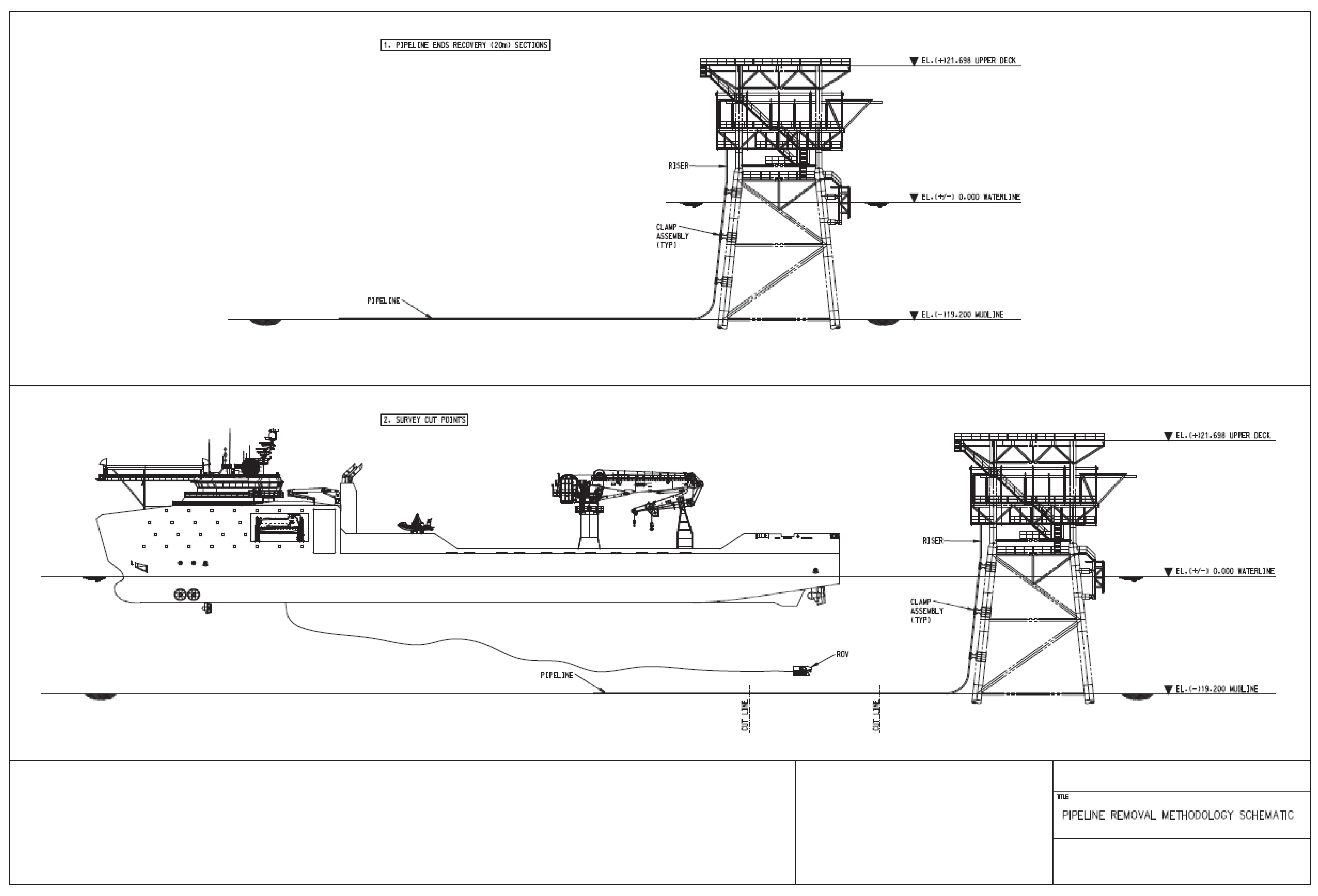
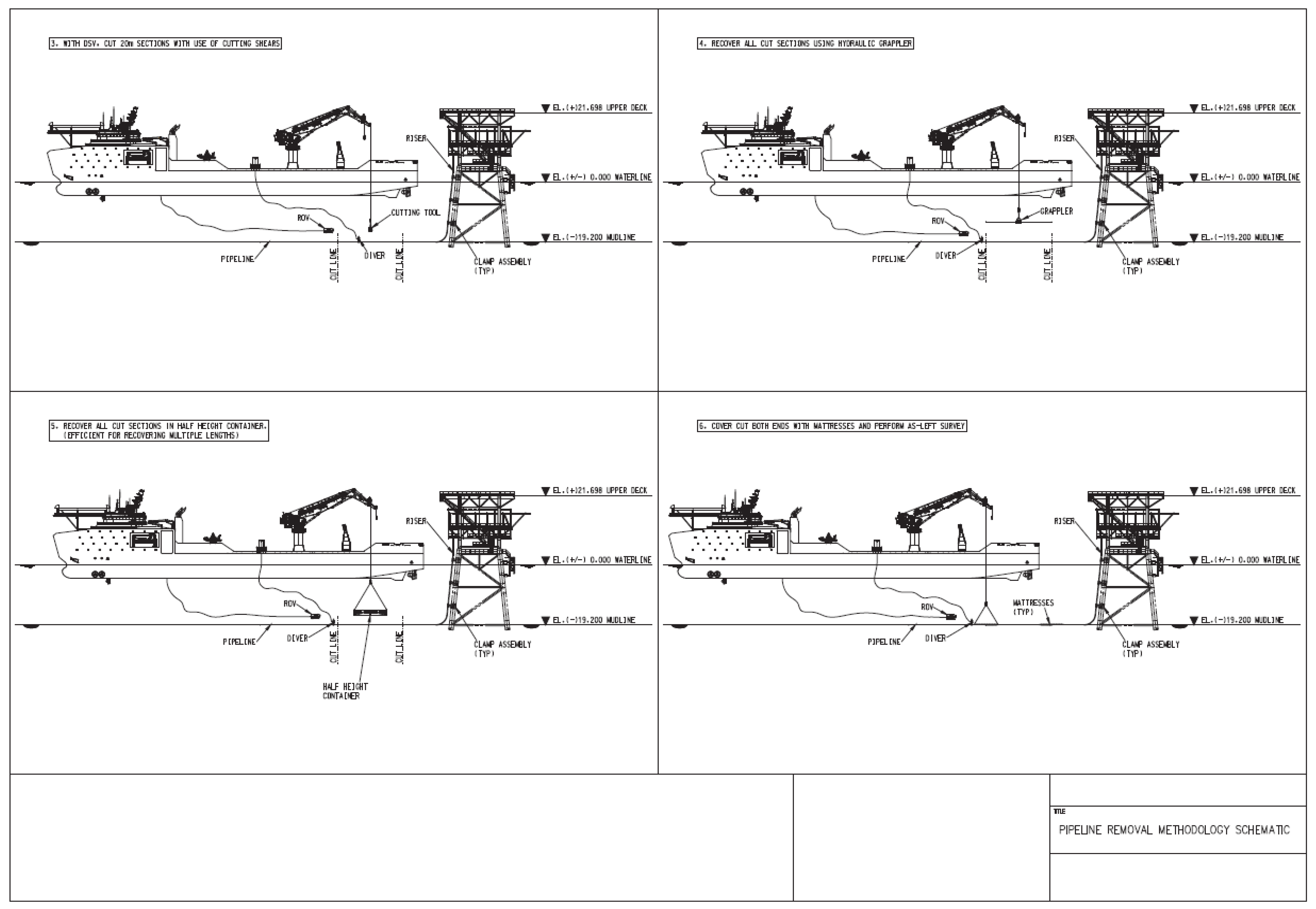
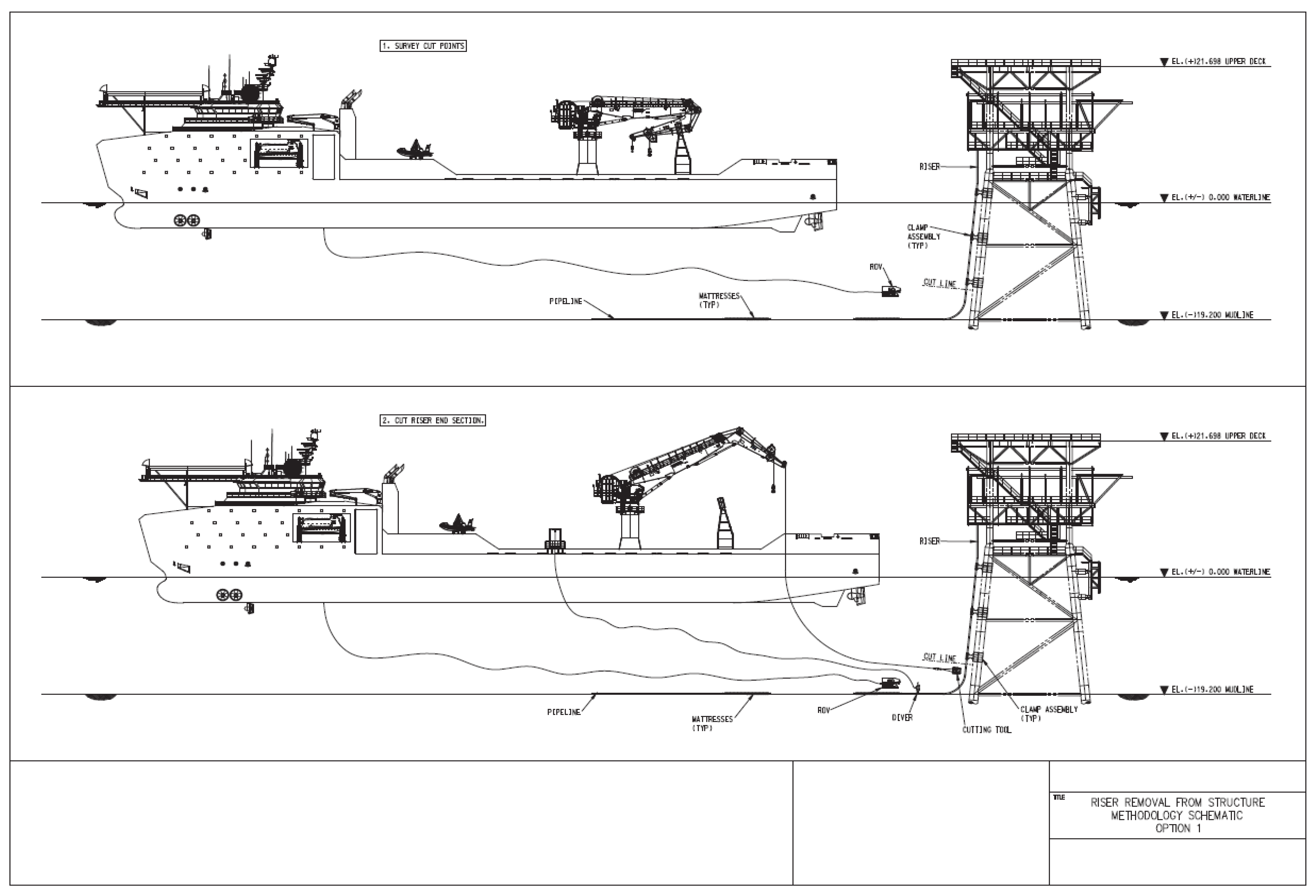
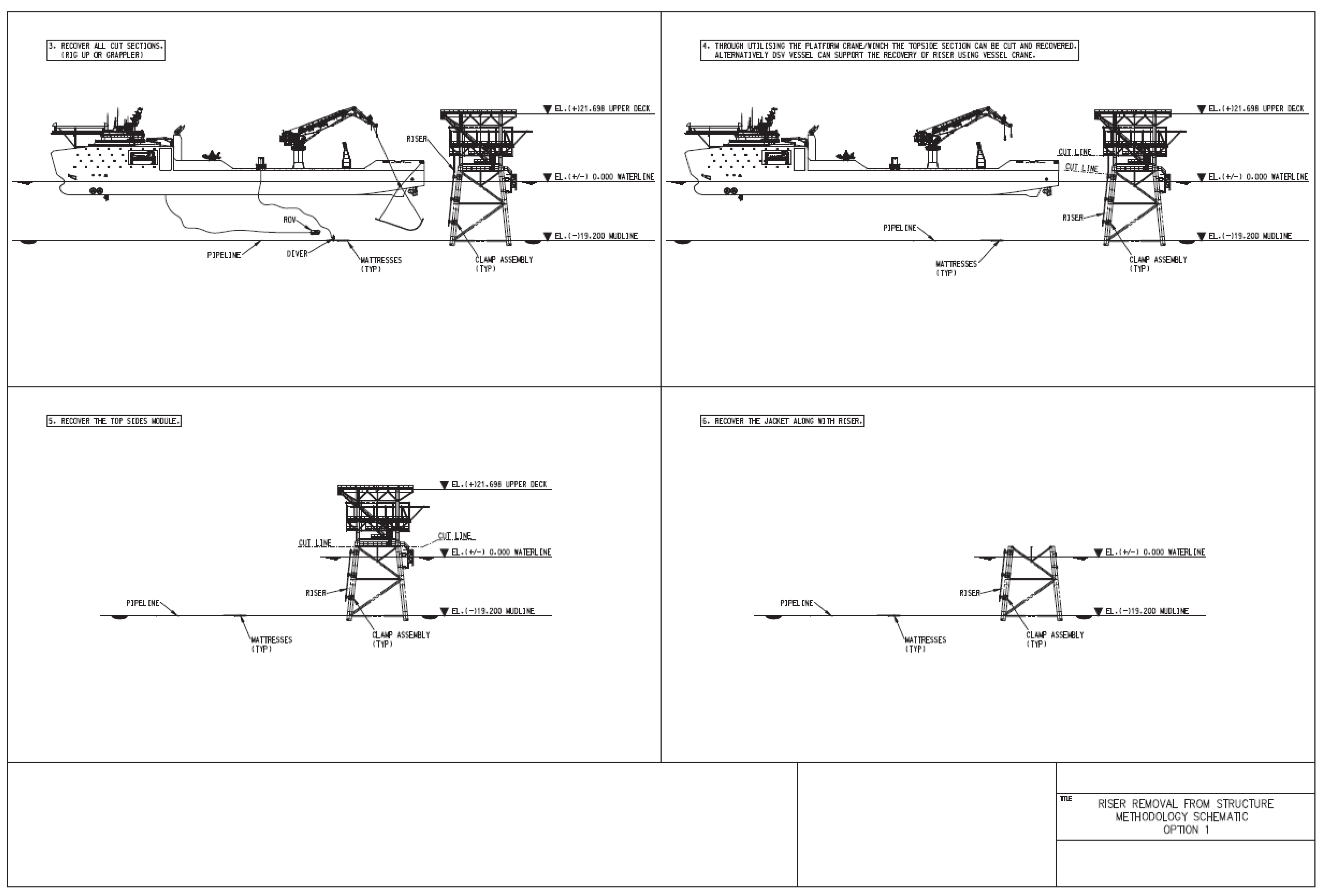
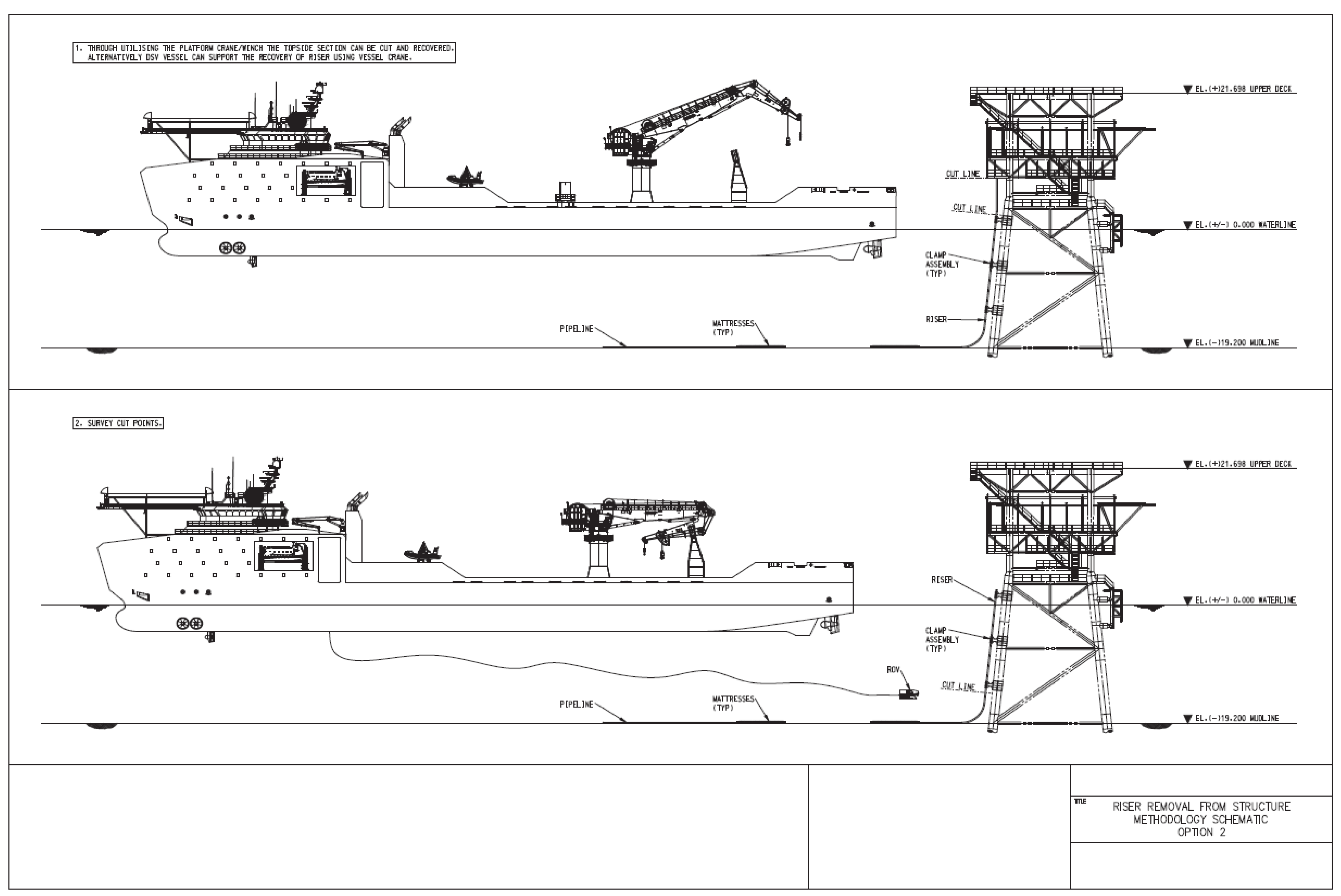
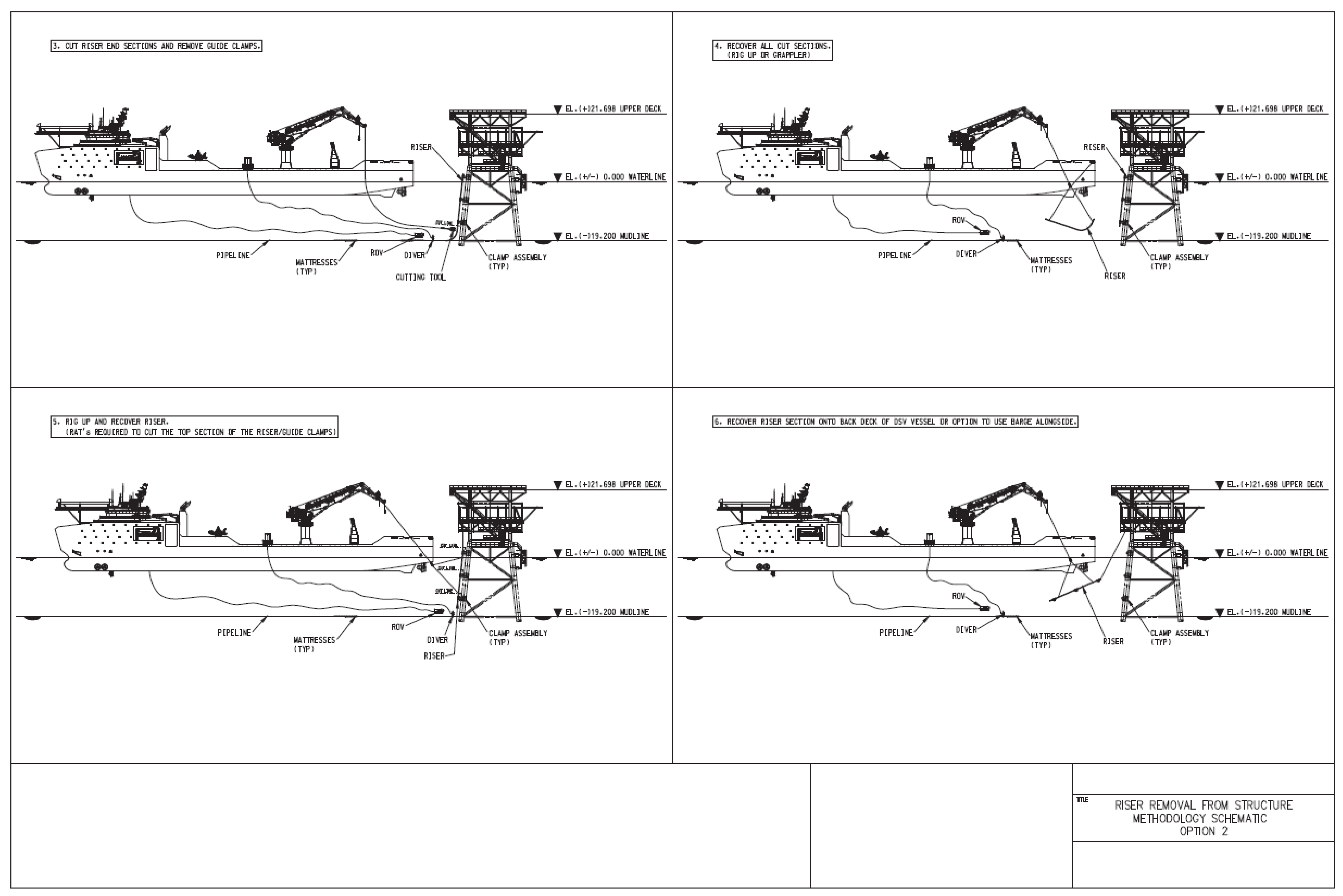
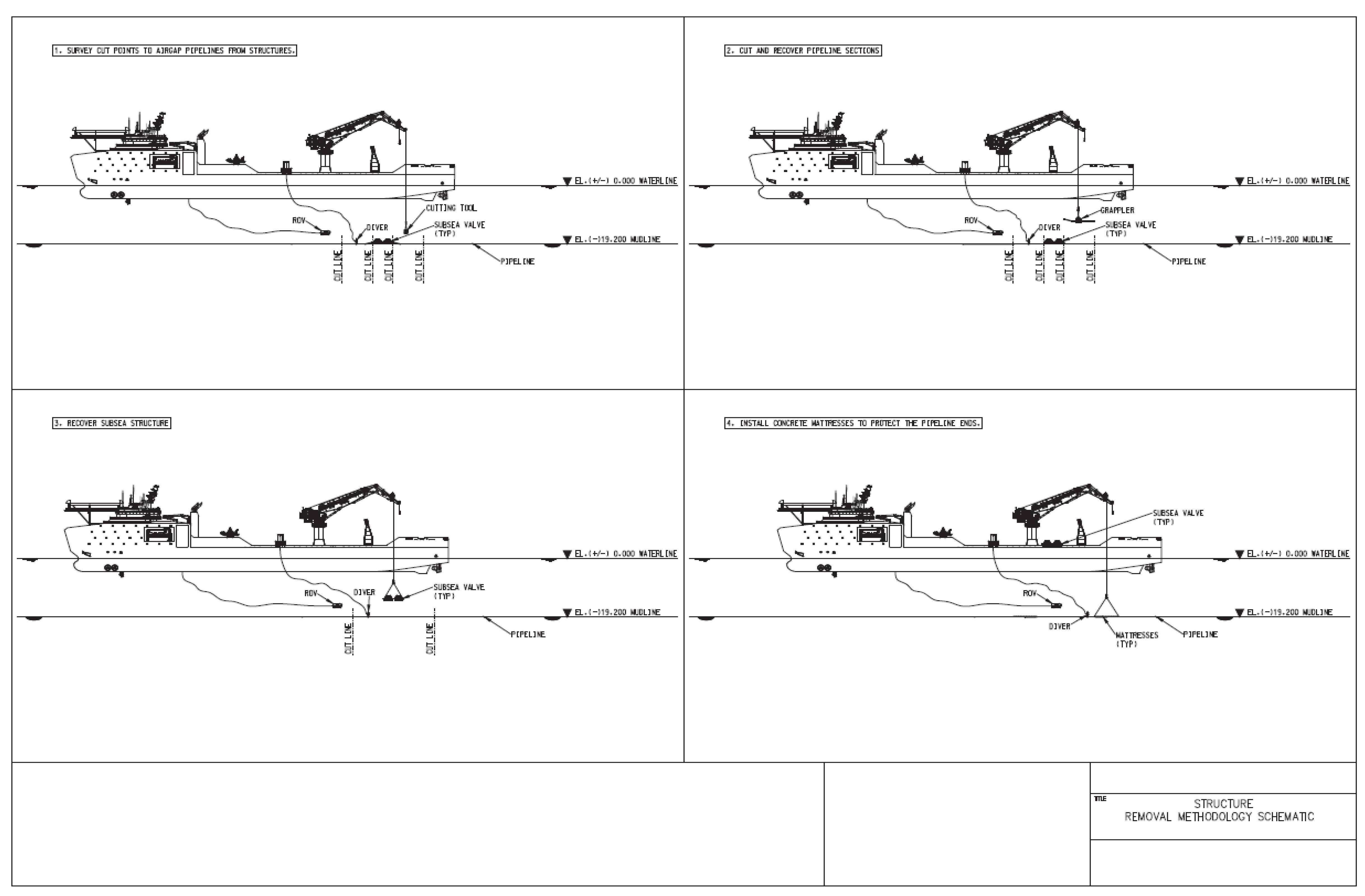
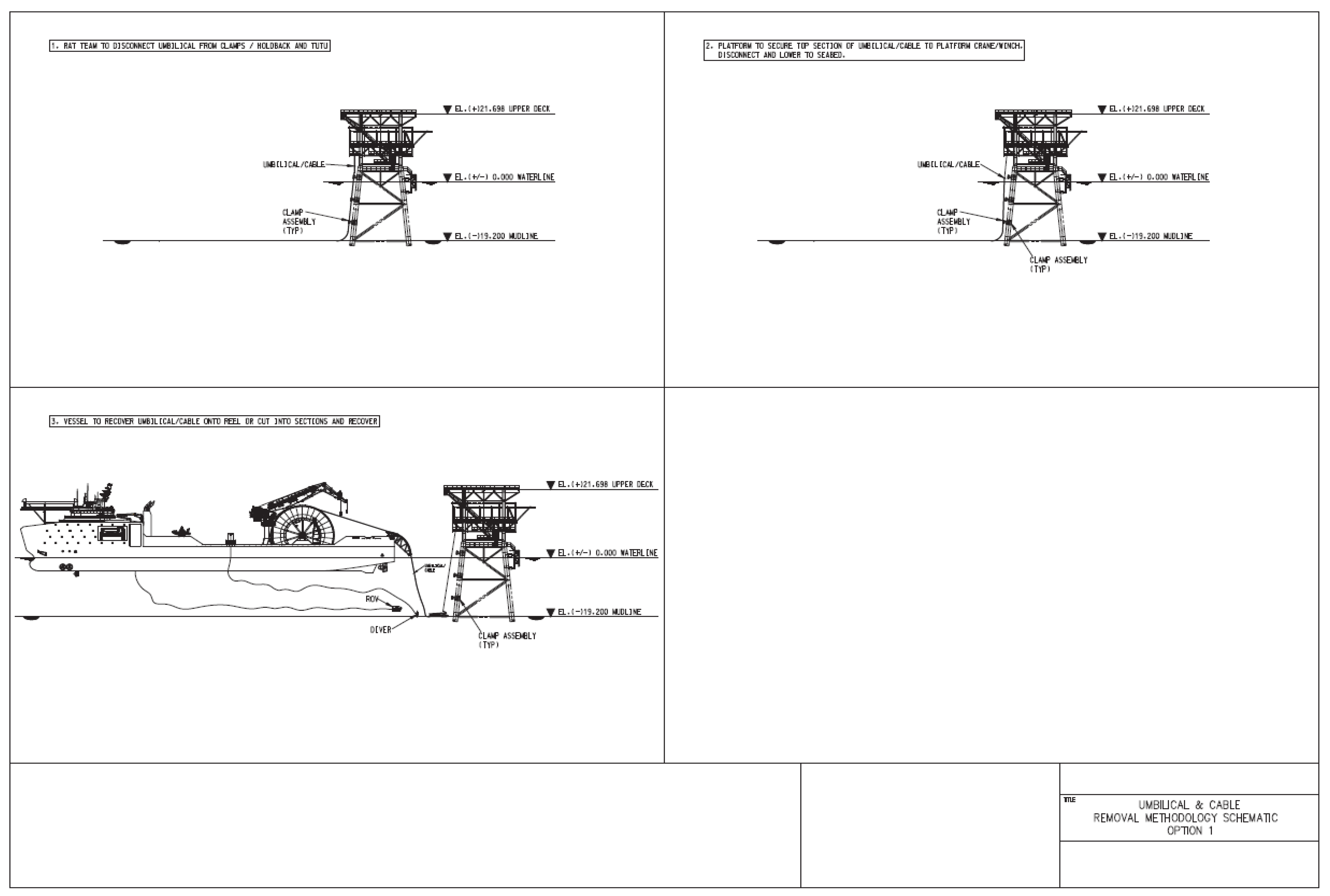
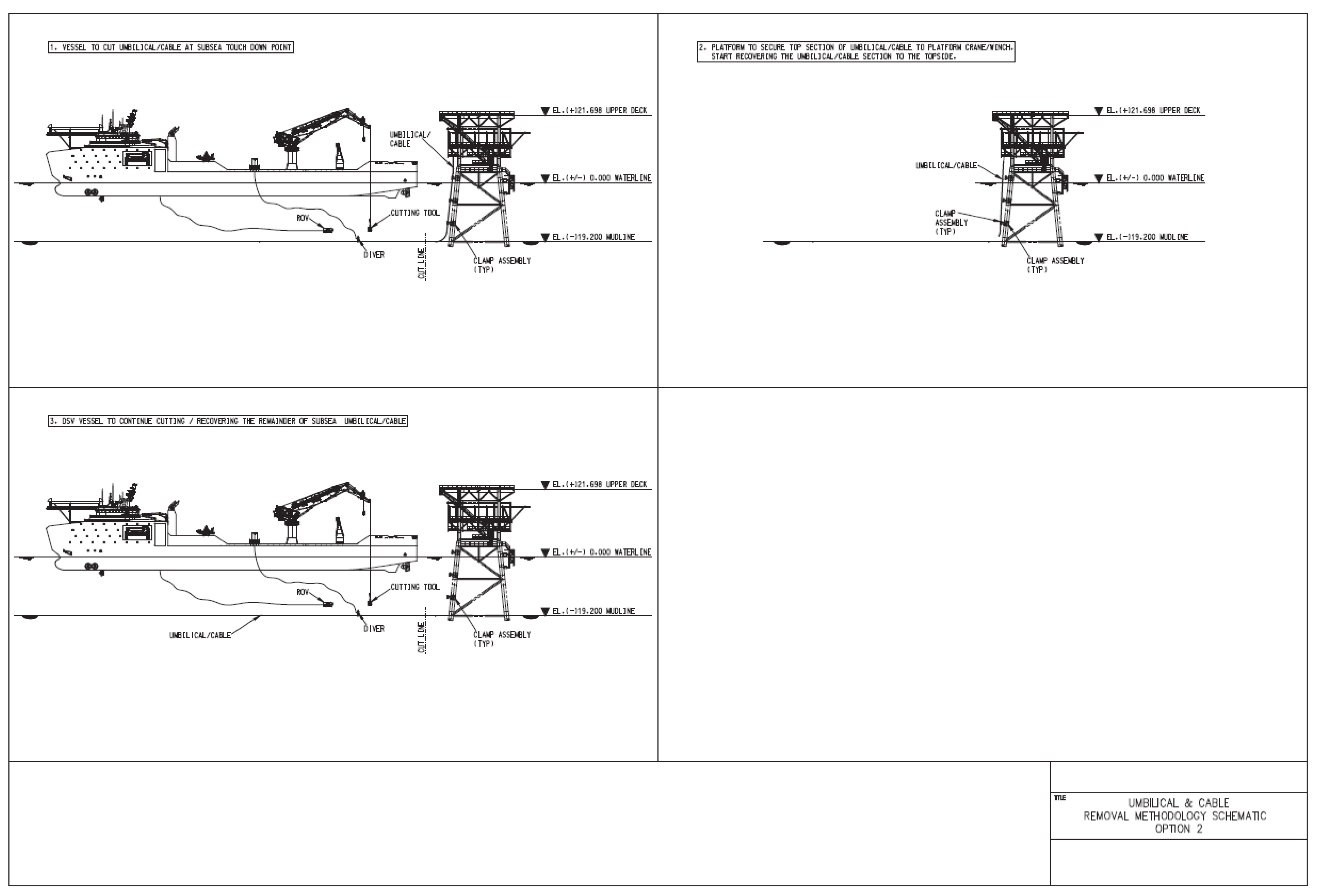
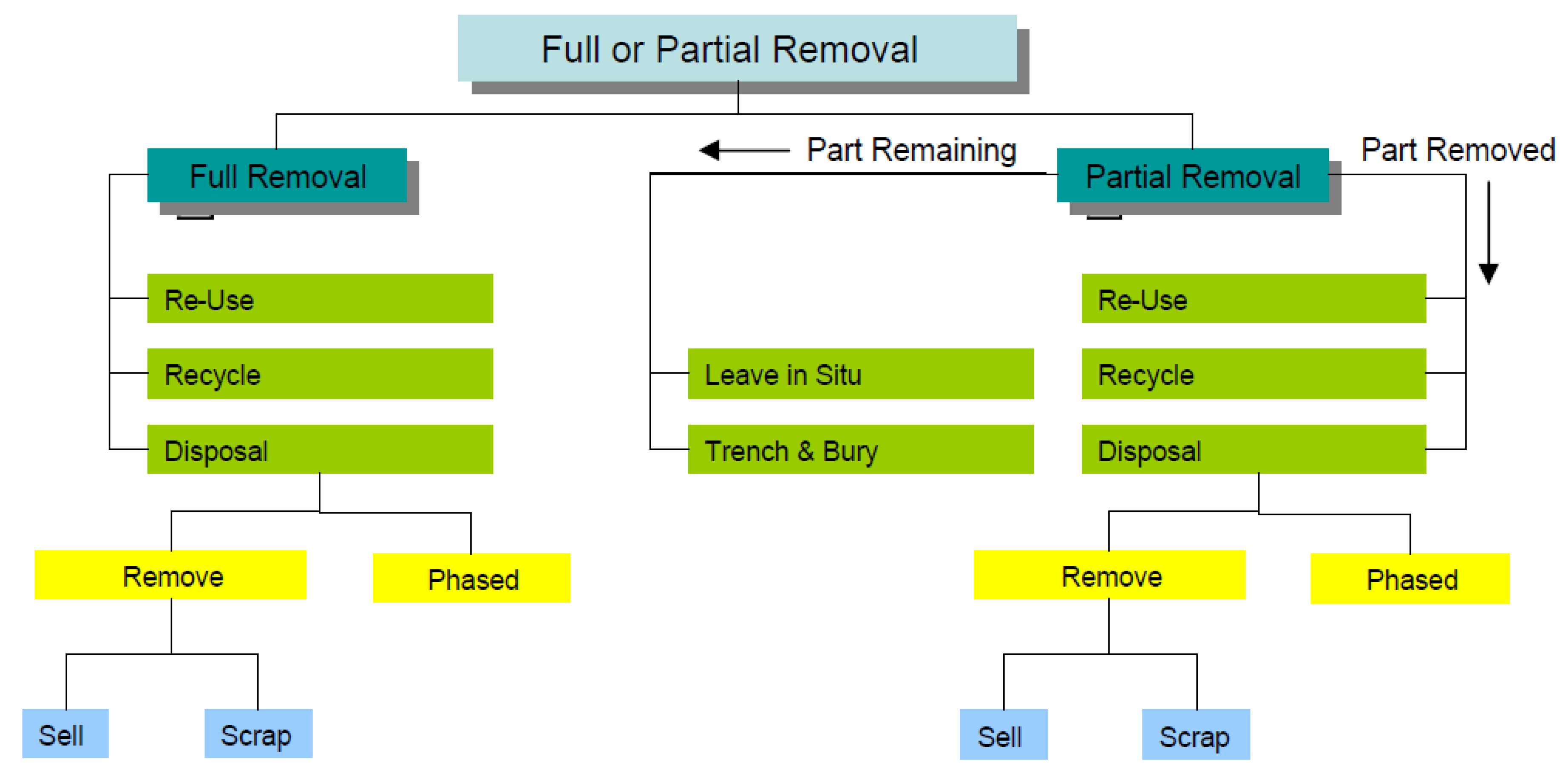
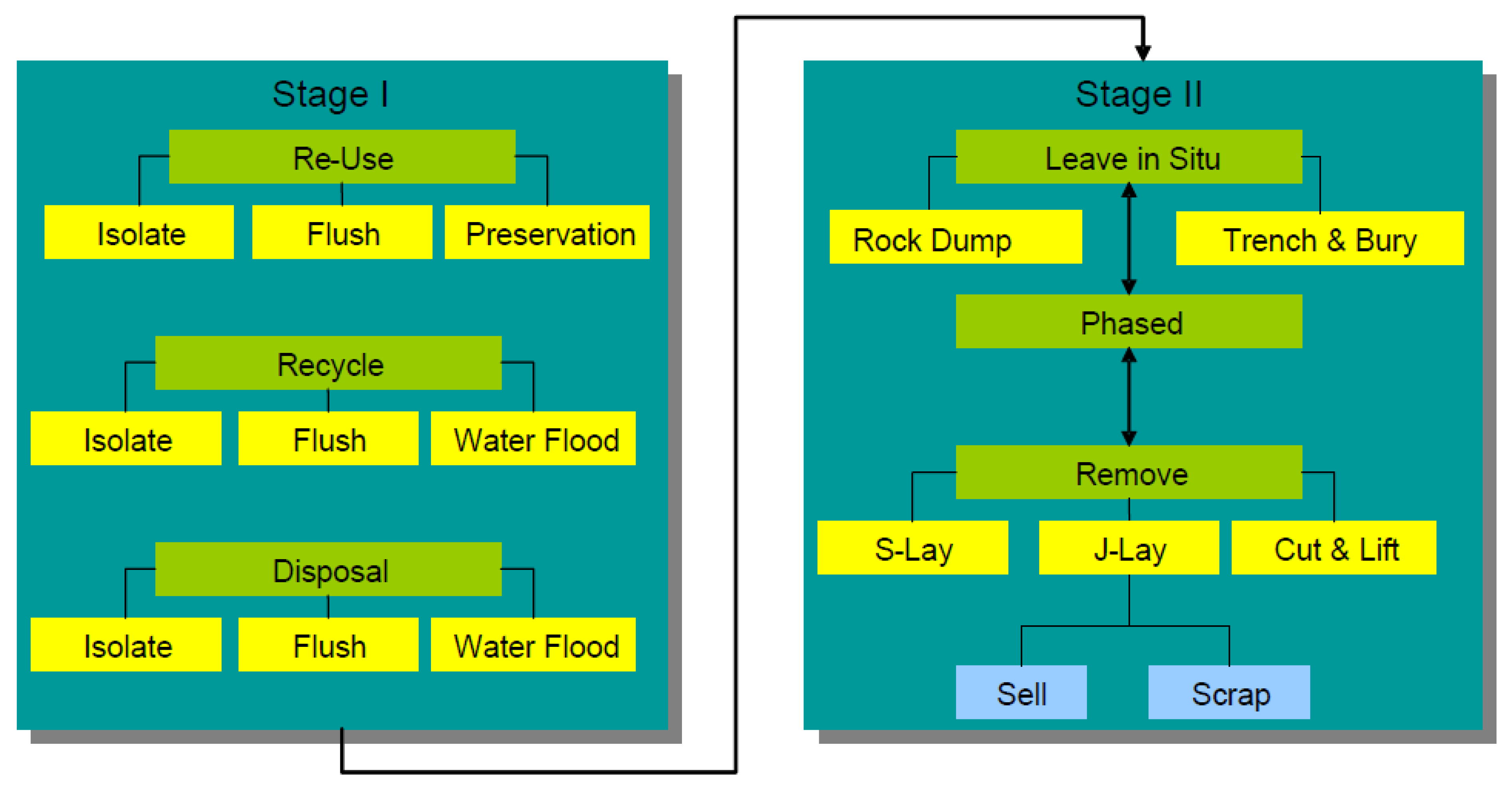
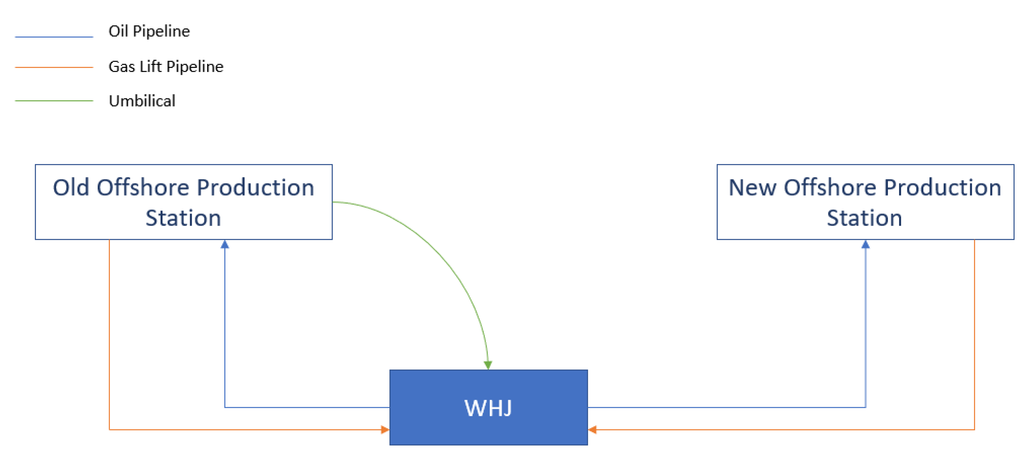
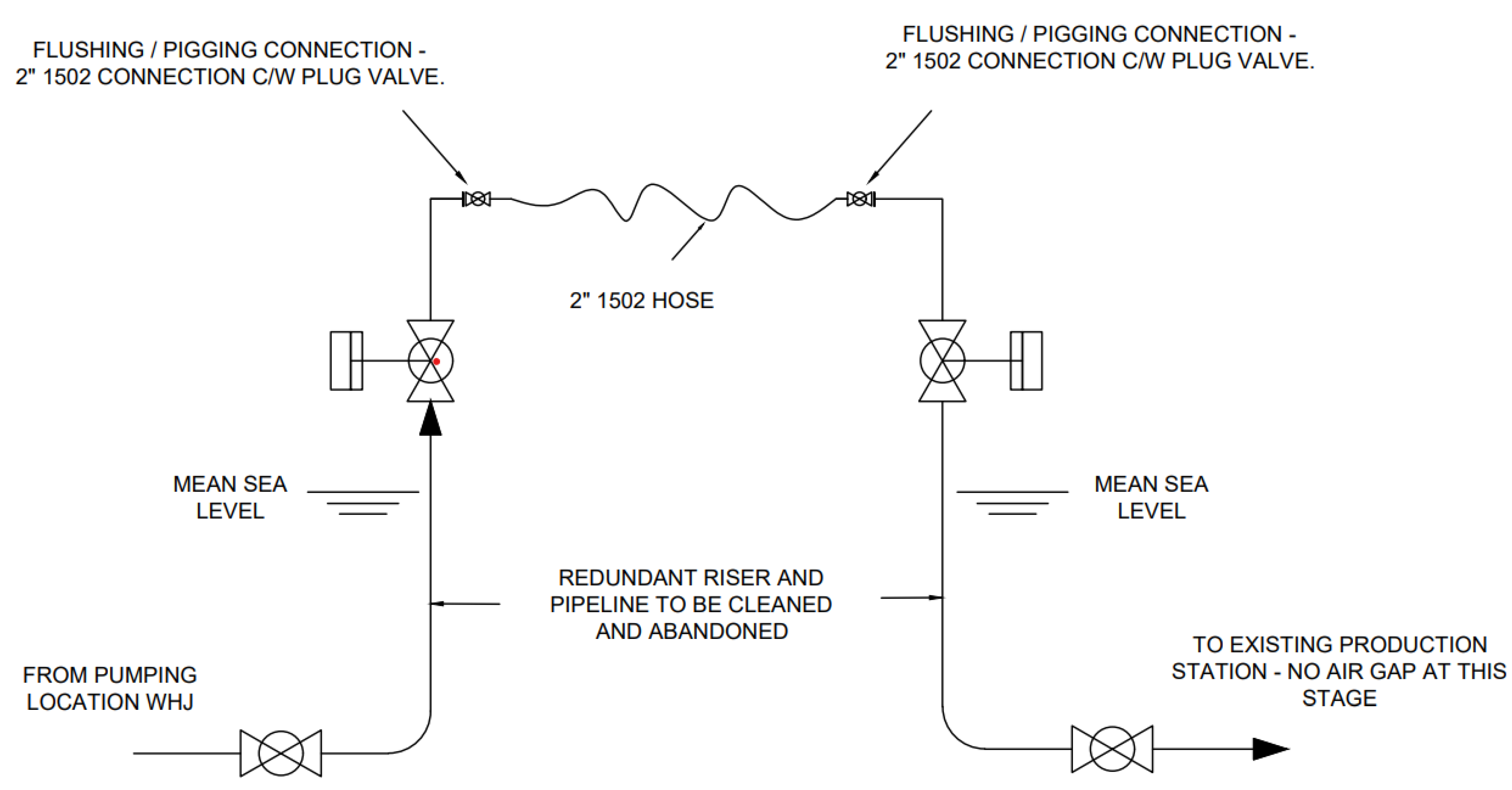
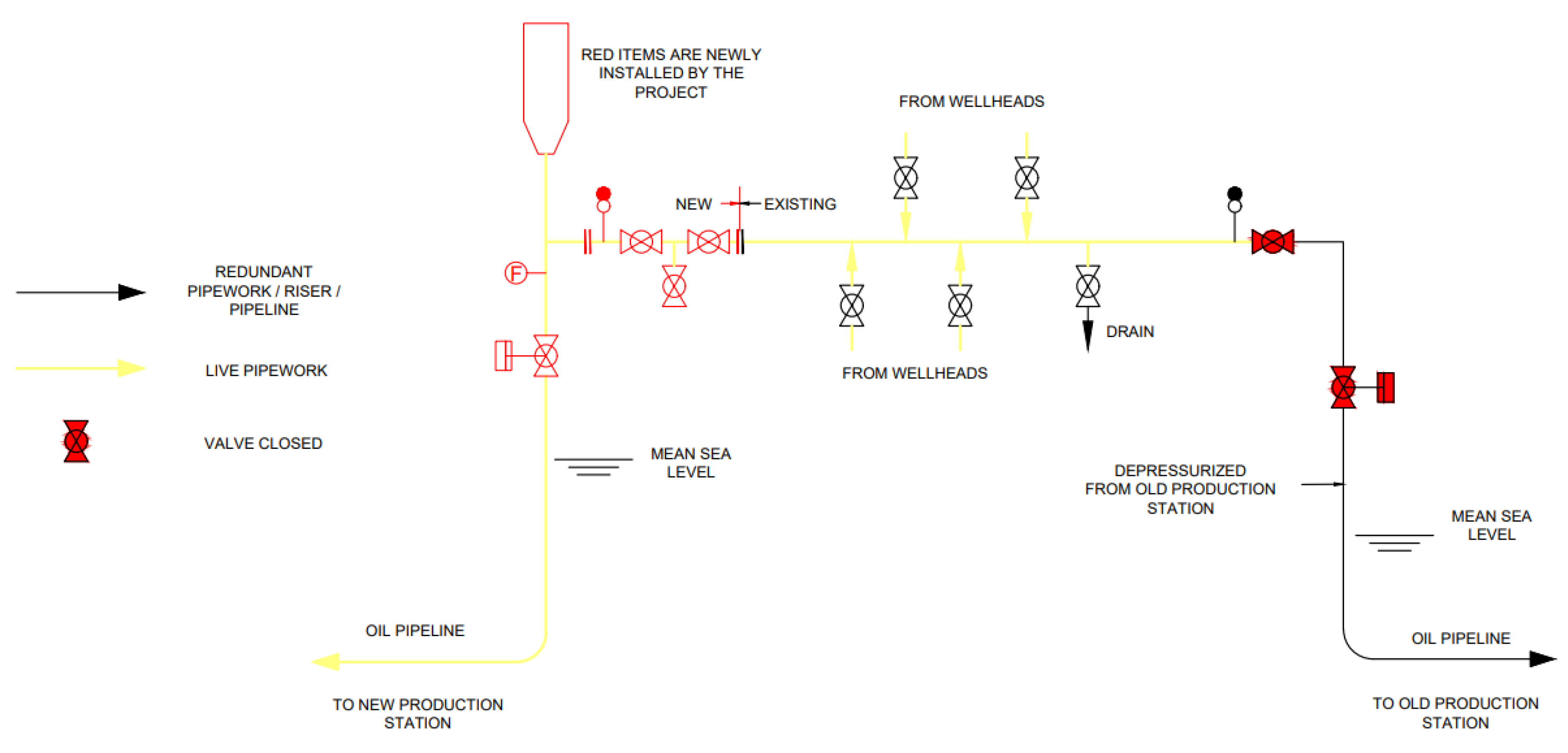
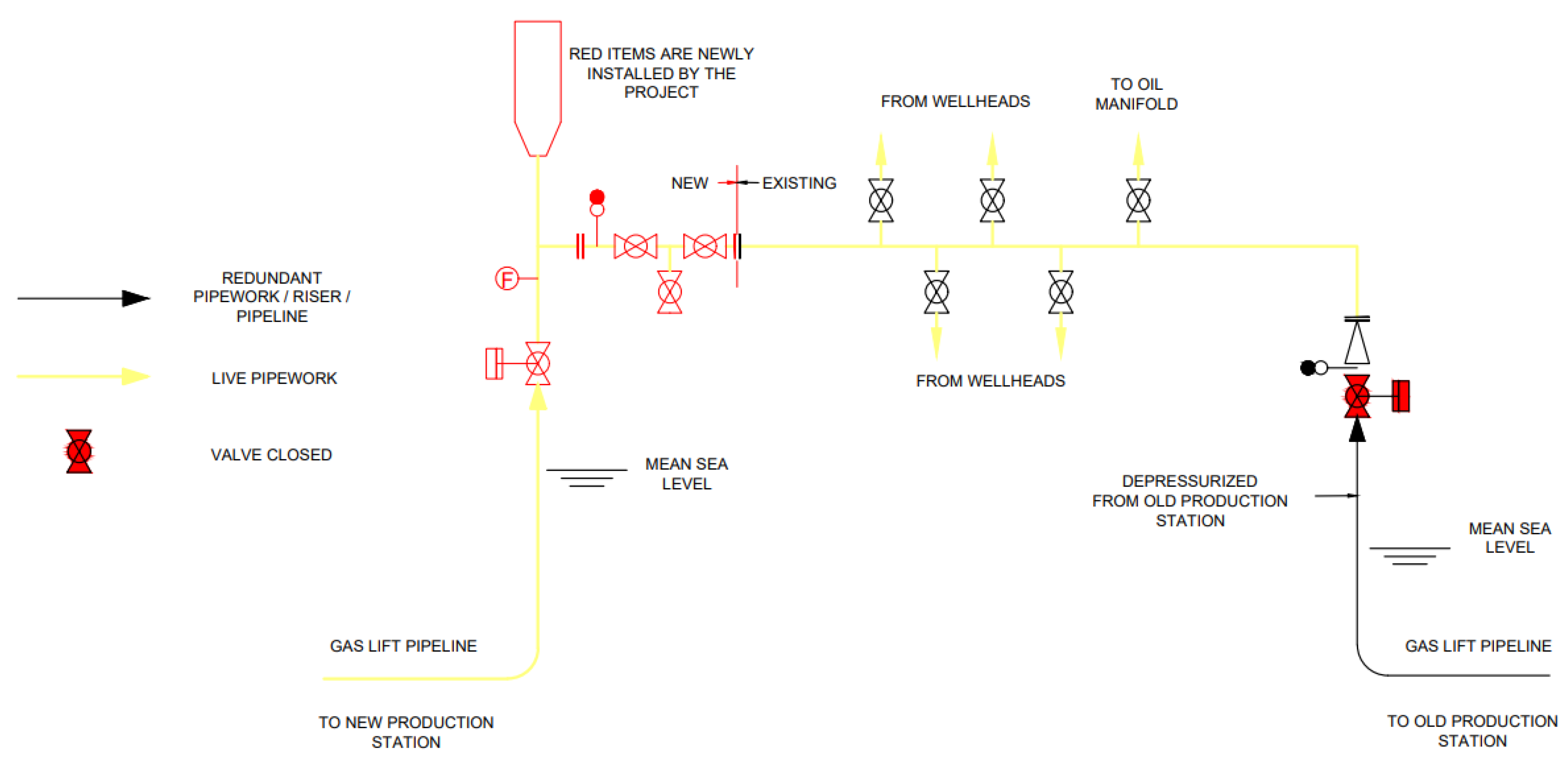
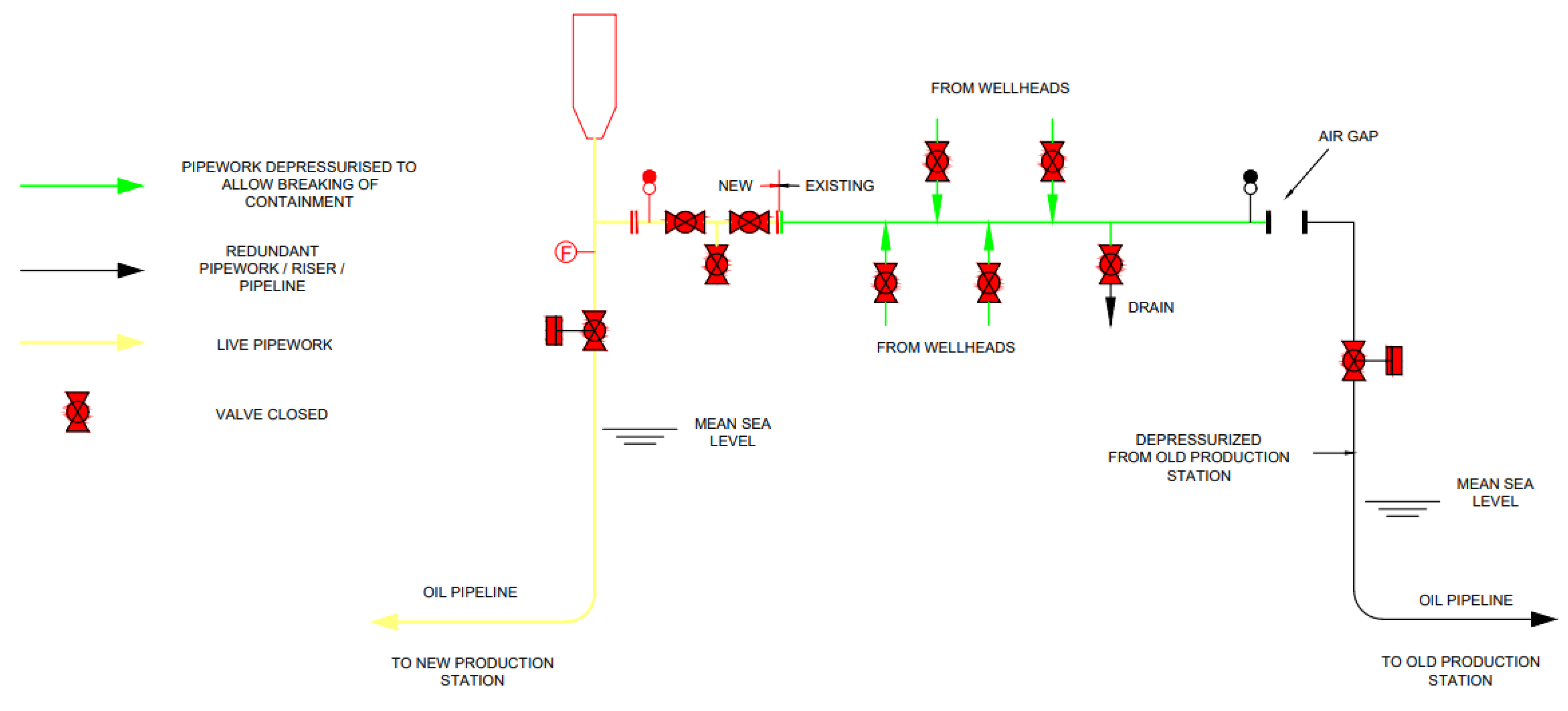
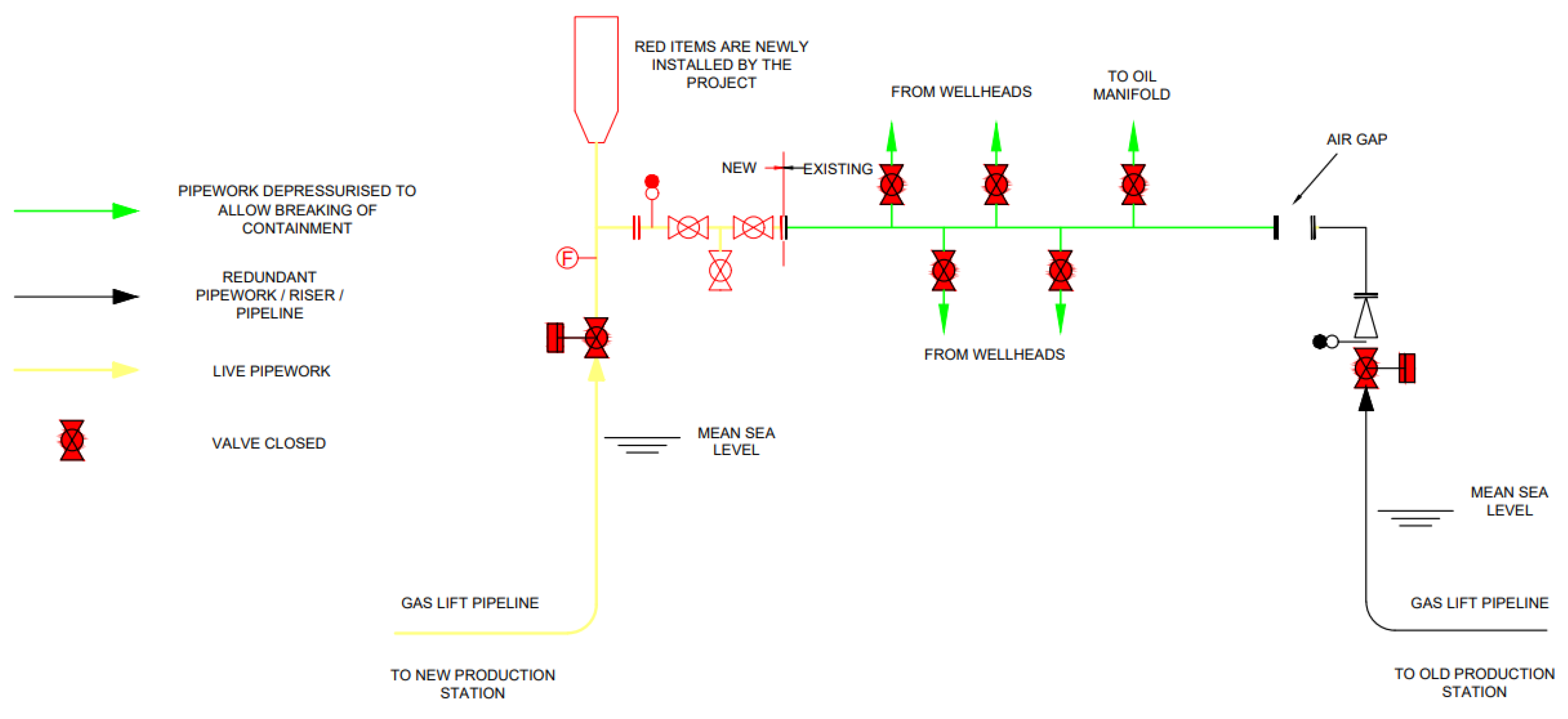

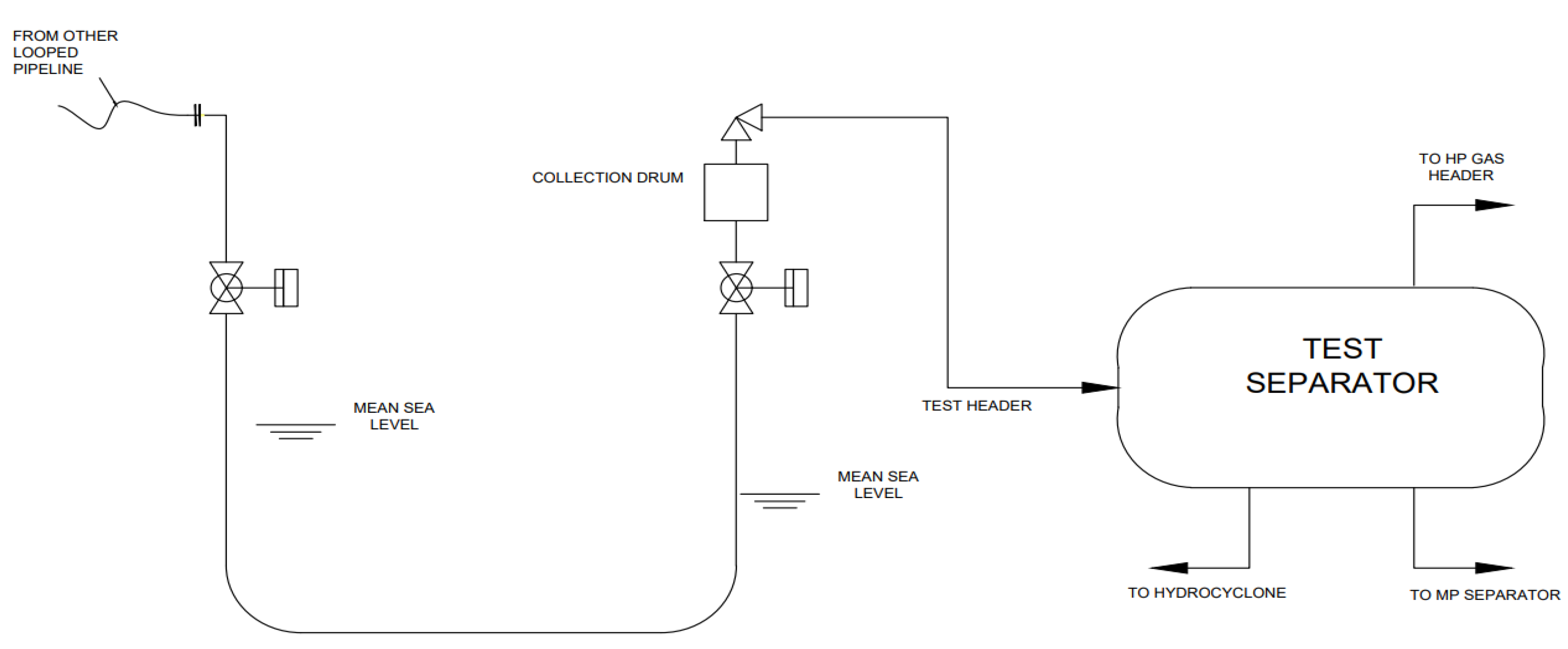

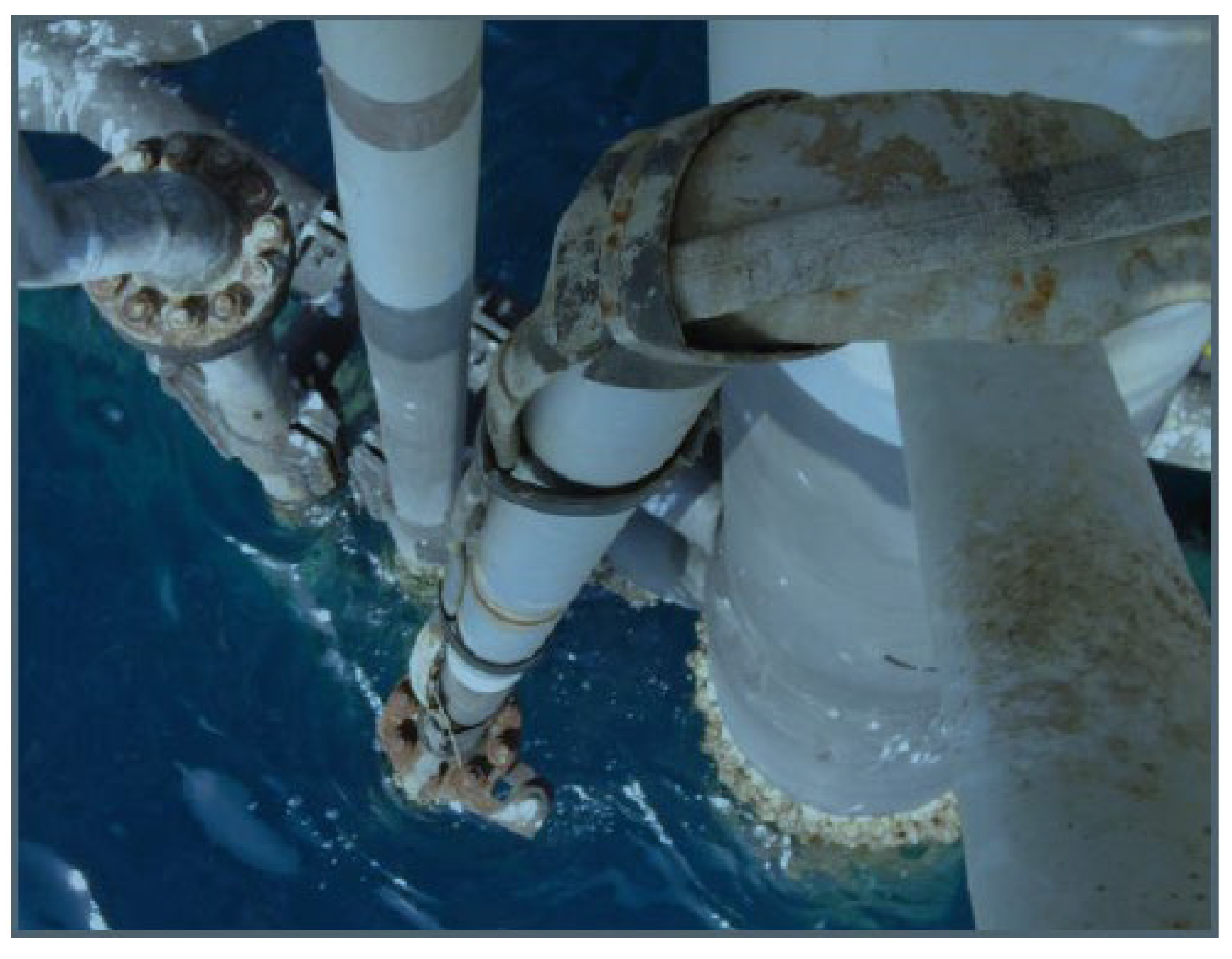
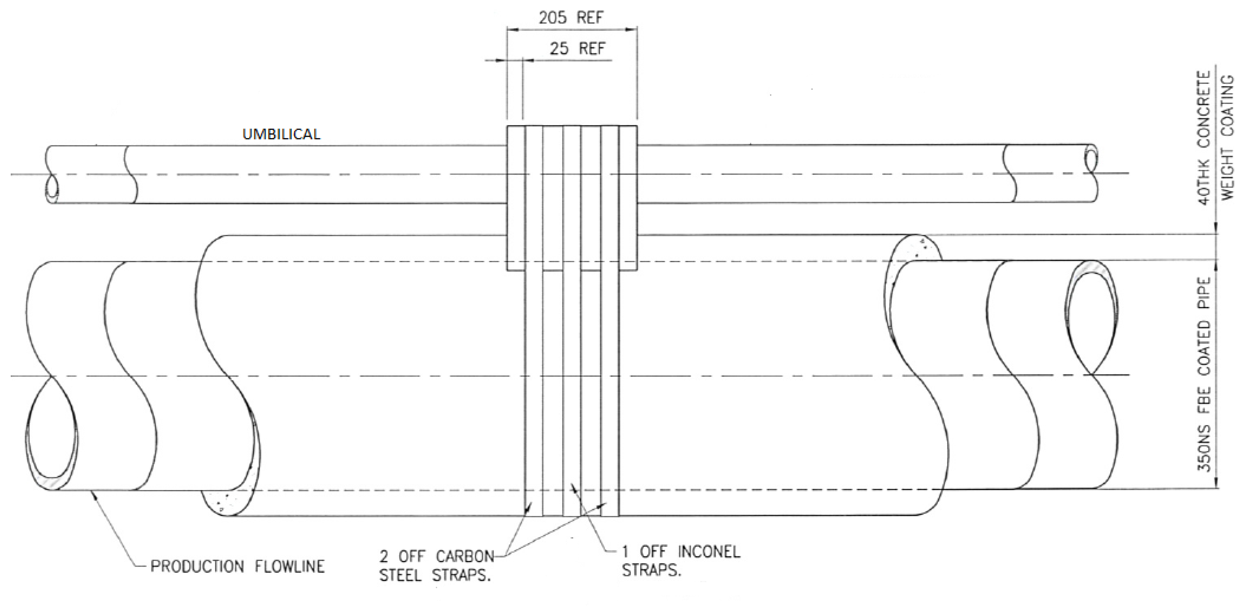

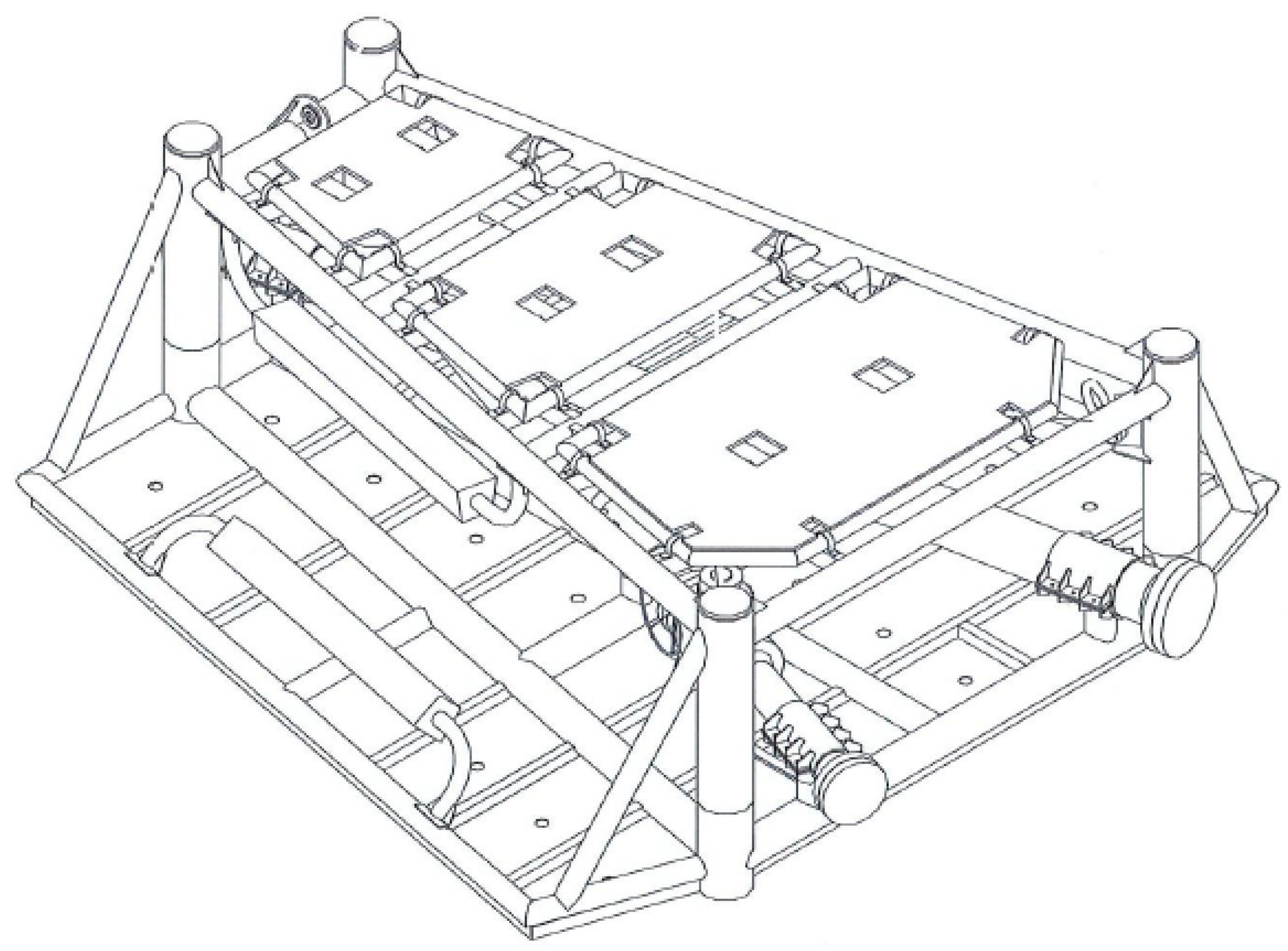
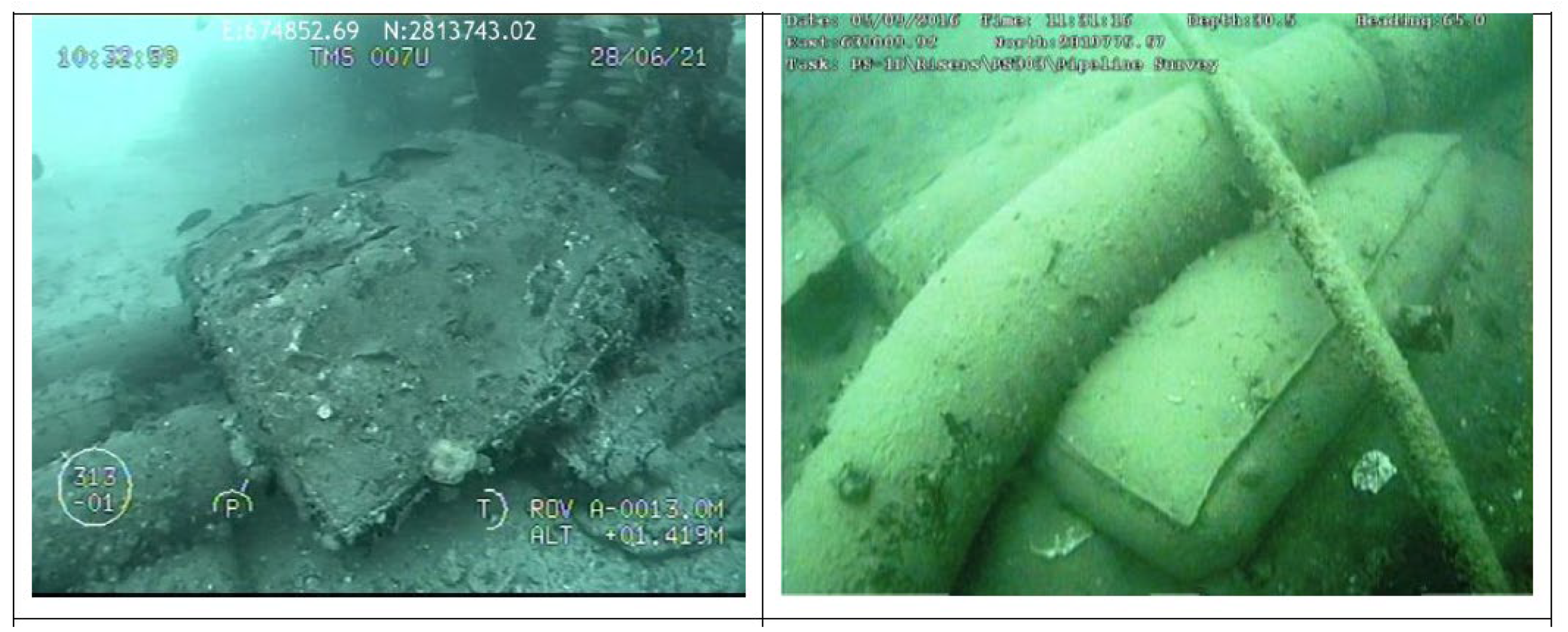

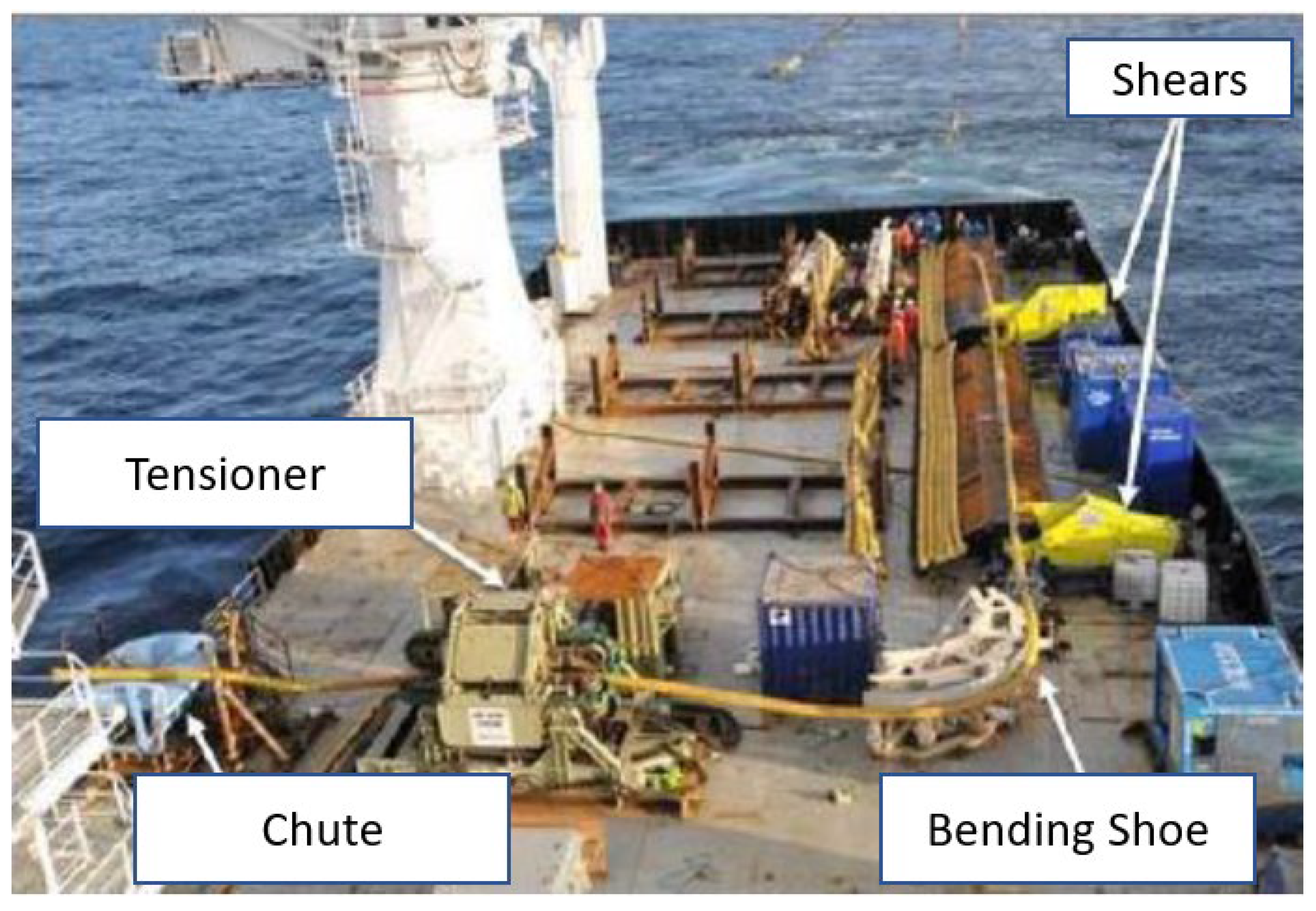
