Article

An Underwater Triboelectric Biomechanical Energy Harvester to Power the Electronic Tag of Marine Life

1
Dalian Key Lab of Marine Micro/Nano Energy and Self-Powered Systems, Marine Engineering College, Dalian Maritime University, Dalian 116026, China
2
Collaborative Innovation Research Institute of Autonomous Ship, Dalian Maritime University, Dalian 116026, China
3
Intelligent Biomimetic Design Lab, College of Engineering, Peking University, Beijing 100871, China
*
Authors to whom correspondence should be addressed.
These authors contributed equally to this work.
J. Mar. Sci. Eng. 2023, 11(9), 1766; https://doi.org/10.3390/jmse11091766
Submission received: 4 August 2023 / Revised: 30 August 2023 / Accepted: 8 September 2023 / Published: 9 September 2023
(This article belongs to the Special Issue Advanced Marine Energy Harvesting Technologies)

Abstract

:
Implantable electronic tags are crucial for the conservation of marine biodiversity. However, the power supply associated with these tags remains a significant challenge. In this study, an underwater flexible triboelectric nanogenerator (UF-TENG) was proposed to harvest the biomechanical energy from the movements of marine life, ensuring a consistent power source for the implantable devices. The UF-TENG, which is watertight by the protection of a hydrophobic poly(tetrafluoroethylene) film, consists of high stretchable carbon black-silicone as electrode and silicone as a dielectric material. This innovative design enhances the UF-TENG’s adaptability and biocompatibility with marine organisms. The UF-TENG’s performance was rigorously assessed under various conditions. Experimental data highlight a peak output of 14 V, 0.43 μA and 38 nC, with a peak power of 2.9 μW from only one unit. Notably, its performance exhibited minimal degradation even after three weeks, showing its excellent robustness. Furthermore, the UF-TENG is promising in the self-powered sensing of the environmental parameter and the marine life movement. Finally, a continuous power supply of an underwater temperature is achieved by paralleling UF-TENGs. These findings indicate the broad potential of UF-TENG technology in powering implantable electronic tags.

1. Introduction

Marine biodiversity significantly contributes to ecosystem services (regulation and provisioning), enhancing the stability and equilibrium of marine ecosystems while also offering substantial economic resources and wealth to humanity [1,2,3]. Nevertheless, marine biodiversity faces myriad challenges stemming from various human activities, such as overfishing, wastewater discharge into oceans, and oil spills [4,5,6]. Hence, the formulation of conservation strategies is indispensable to effectively protect marine biodiversity [7,8]. The efficacy of these conservation strategies largely hinges on routine monitoring of habitat utilization, movement patterns, and behaviors of marine species across daily to seasonal timescales. The implantable electronic tag, a compact device affixed to or implanted within marine life [9,10,11], consistently collects data regarding the position, movements, and physiological parameters using mobile receivers or stationary loggers [12,13,14].
Implantable electronic tagging has offered indispensable data support for the development of strategies aimed at preserving marine biodiversity [15,16,17]. Block et al. deployed 4,306 tags across 23 species in the North Pacific Ocean, creating a tracking dataset of unparalleled magnitude [18]. These data collected by electronic tags constitute the cornerstone for the spatial management of vast marine ecosystems. However, the predominant power source for these tags in practical scenarios remains lithium batteries, which inherently limit their operational longevity [19,20]. Regular battery replacements are essential for maintaining the long-term functioning of these devices. Replacement procedures risk causing morbidity or mortality amongst marine species, besides escalating operational costs and potentially causing irreversible harm to marine life [21,22,23]. Consequently, a sustainable energy supply solution is imperative.
Energy harvesting and conversion devices using nanotechnology have received increasing interest [24]. The piezoelectric nanogenerator (PENG) has demonstrated its ability to harvest energy for numerous electronic devices [25,26,27], in addition to being utilized in a variety of sensors such as those for bridge vibration and temperature [28,29,30]. Alternatively, the triboelectric nanogenerator (TENG), which operates on the principle of Maxwell’s displacement current [31,32,33,34], has garnered significant attention due to its notable advantages, including heightened energy harvesting efficiency and a wide range of excitation sources. As a result, the adoption of TENG has expanded across various domains, encompassing wearable technology, electronic skin, and energy harvesting [35,36,37]. Wang et al. have presented a multifunctional fish-wearable data surveillance platform aimed at studying fish kinematics, which is built on an air sac Triboelectric Nanogenerator (AS-TENG) featuring an antibacterial coating [38]. The AS-TENG operates as a self-powered sensory module to monitor fish swimming behavior. Wang et al. have proposed an underwater flag-like TENG predicated on the flow-induced vibration for powering sensors in the Internet of Things [39]. However, no triboelectric nanogenerator currently exists that is designed explicitly for harvesting marine bioenergy to power implantable electronic tags.
This study proposed a UF-TENG for harnessing oceanic bioenergy derived from marine life. The device incorporates a flexible biocompatible silicone material as its dielectric layer, carbon black(CB)-silicone as the electrode, and a poly(tetrafluoroethylene)(PTFE) film with excellent hydrophobicity as the sealing material [40,41]. The UF-TENG can seamlessly attach to marine life, translating their movements into electrical energy. Furthermore, voltage signal analysis facilitates the observation of marine organisms’ movement patterns and surrounding environment. The UF-TENG exhibits excellent waterproof and stretchable properties. In contrast to traditional lithium batteries, the UF-TENG can continuously power implantable electronic tags, thereby enabling these tags to track the movement patterns of marine life over extended durations.

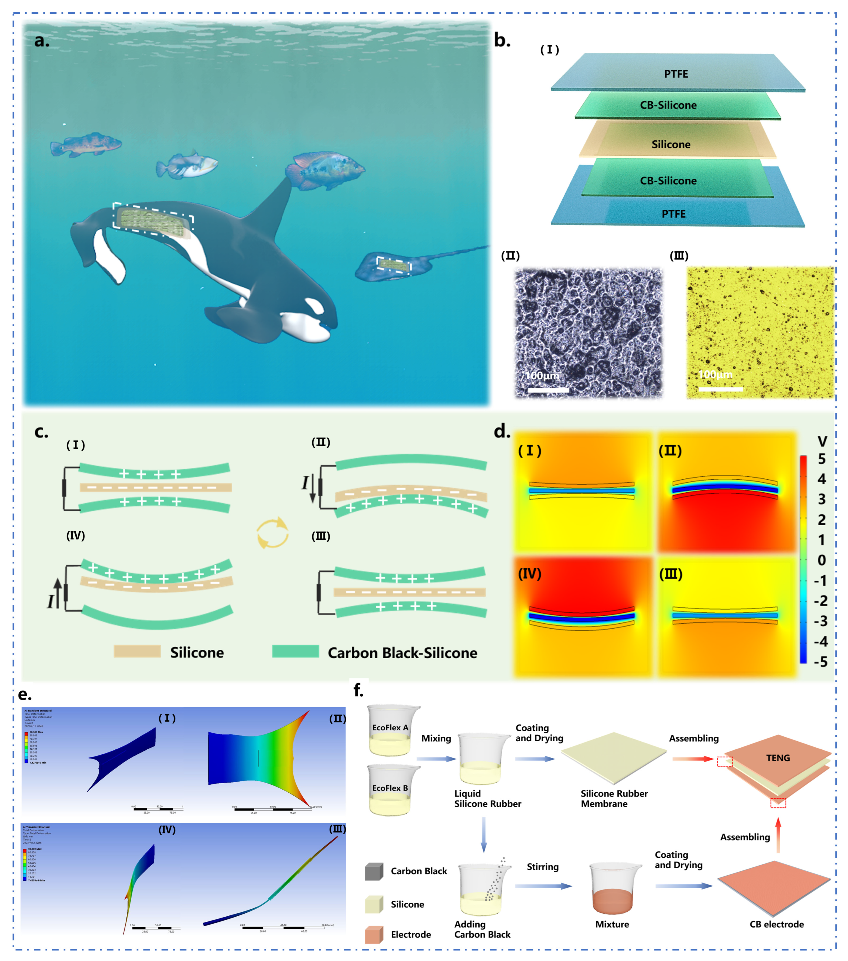
2. Structure and Working Principle

Marine life can produce mechanical energy with every movement, but there is still a lack of effective energy-harvesting methods. This phenomenon served as the inspiration for the development of a UF-TENG that can attach to the bodies of marine life, converting the energy generated by their movements into electrical energy for implantable electronic tags in Figure 1a. This device ensures both the long-term battery life of the implantable electronic tag and mitigates the adverse impact of traditional lithium batteries on marine life and the marine environment. As depicted in Figure 1b(I), the UF-TENG is composed of CB-silicone as the electrode, silicone as the dielectric, and a hydrophobic PTFE film for sealing. Both the conductive CB-silicone film surface and silicone surface underwent polishing using 10,000-mesh sandpaper to enhance their surface roughness. The surface roughness enhancement enlarges the contact area between the two electrodes, which effectively hoists the sensitivity and output performance of UF-TENG. The microstructure of the CB-silicone film and silicone film is illustrated in Figure 1b(II,III). Finally, these components are assembled by applying PTFE waterproof tape. It is worth noting that although PTFE has a certain electron-donating ability [42], it is in direct contact with water and exchanges ions with water, which has little effect on the output of UF-TENG.
Figure 1c shows the working principle of UF-TENG, which consists of four stages. In the initial stage, an air layer separates the CB-silicone electrode and the silicone as shown in Figure 1c(I). Electrostatic induction results in equivalent charges being produced on both the CB-silicone electrode and the silicone. When marine life oscillates to one side, the UF-TENG undergoes bending, causing the silicone and CB-silicone electrodes to come into contact, as shown in Figure 1c(II). The silicone has a higher electronegativity than the CB-silicone electrode. Therefore, the surface of CB-silicone has a positive charge and the surface of silicone has a negative charge. When marine life bends and then returns to its original shape, silicone is separated from CB-silicone.
The positive and negative triboelectric charges no longer overlap on the same plane, creating a dipole moment and potential between the two contact surfaces. Free electrons flow through an external circuit to balance the local electric field and generate positive charges on the conductive silicone electrode. The electron flow stops when the distance between the two contact surfaces returns to the initial state, completing the power generation cycle as shown in Figure 1c(III). Figure 1c(IV) shows the cycle repeating as the marine life swings to the opposite side. The electrostatic field distribution of the TENG is calculated using the commercial software COMSOL Multiphysics and is presented in Figure 1d. The simulation results are consistent with the analysis conducted above. Figure 1e presents the finite element analysis of UF-TENG in a fluid environment. The caudal fin material in the simulation mimics the actual marine biological tissue and shows that UF-TENG can deform with the bending of marine life and effectively convert mechanical energy into electrical energy. Supplementary Video S1 shows the state of UF-TENG with the swing of marine life. Figure 1f depicts the process of constructing the UF-TENG, with comprehensive specifics outlined within the “Materials and Methods” segment.

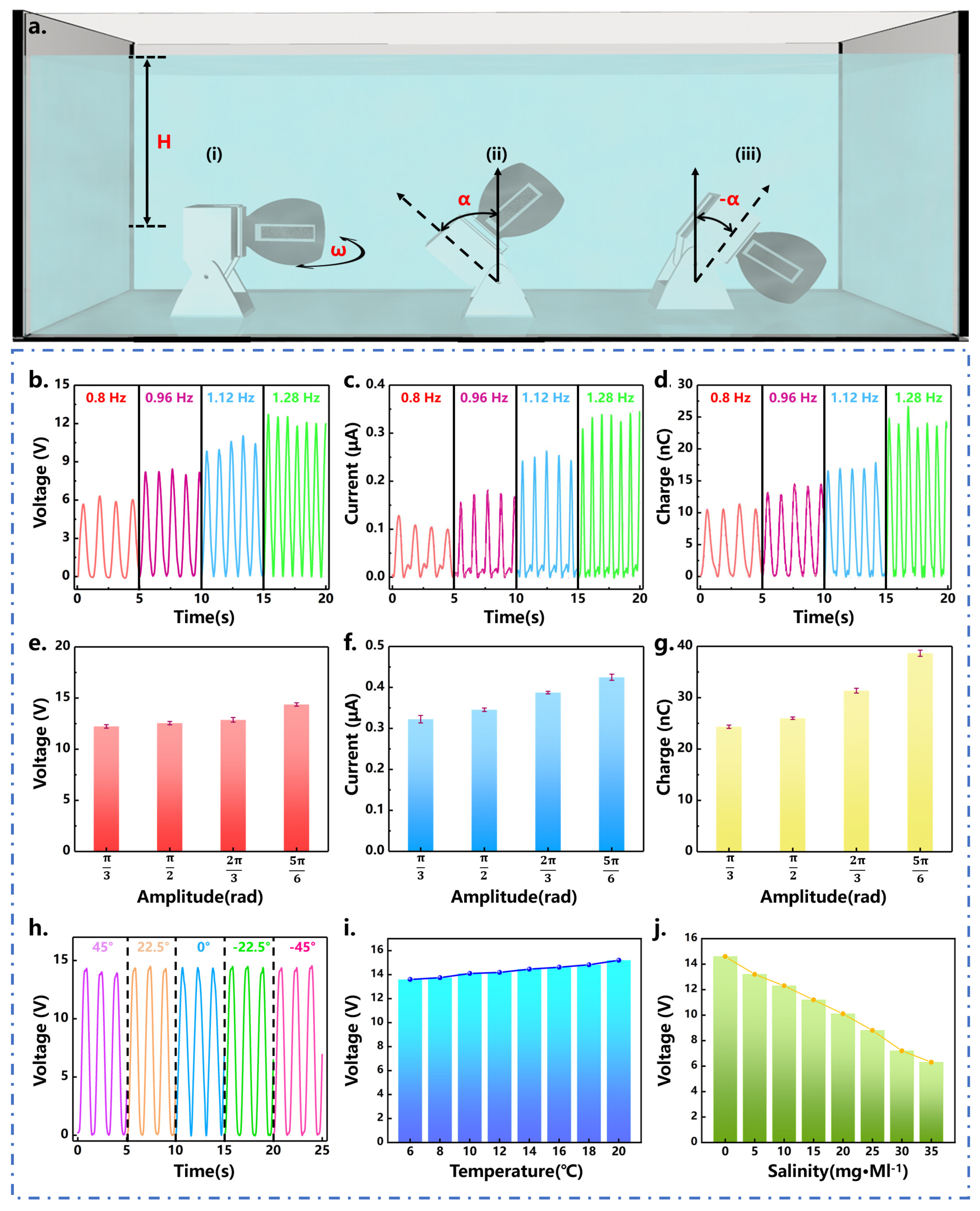
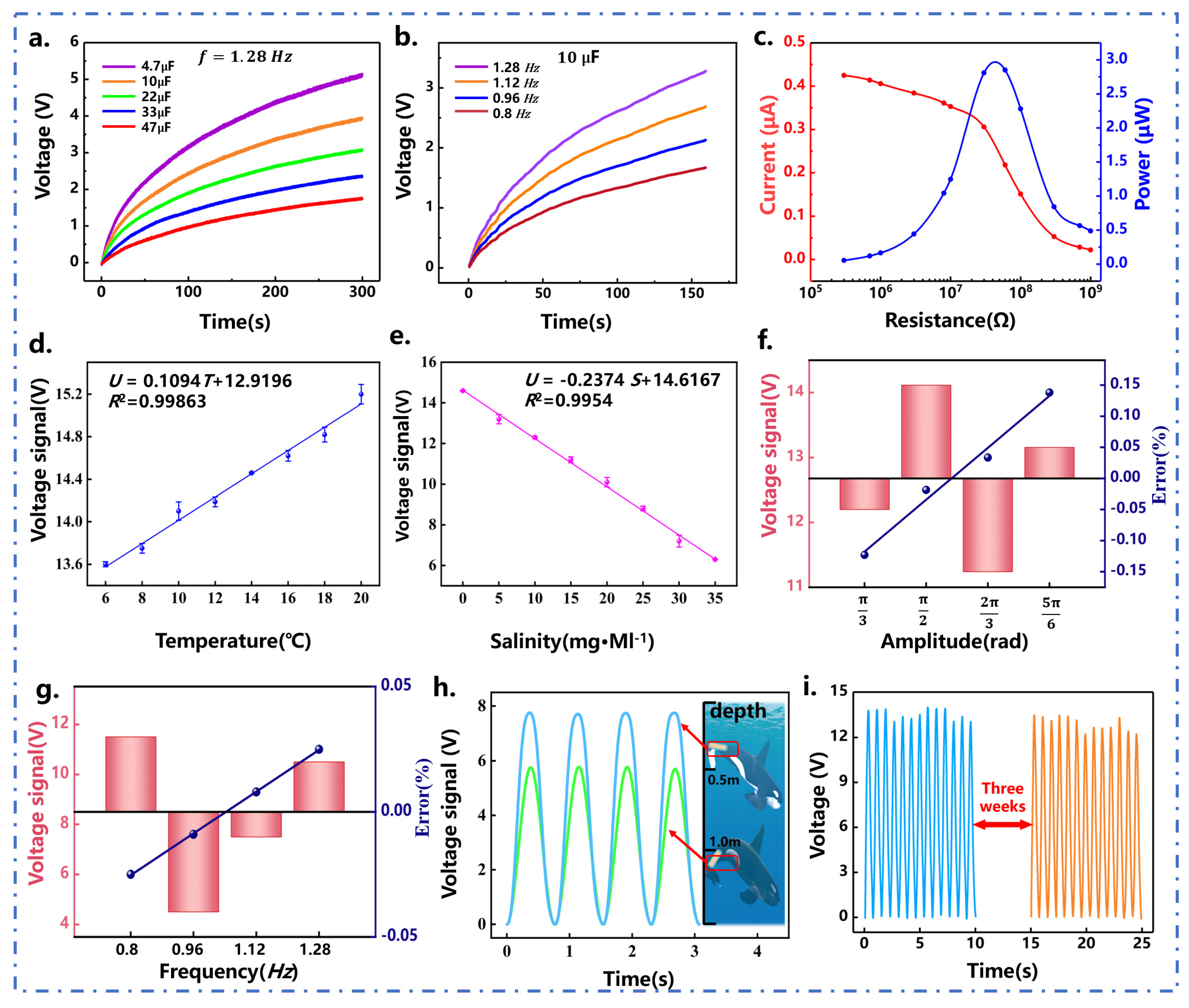
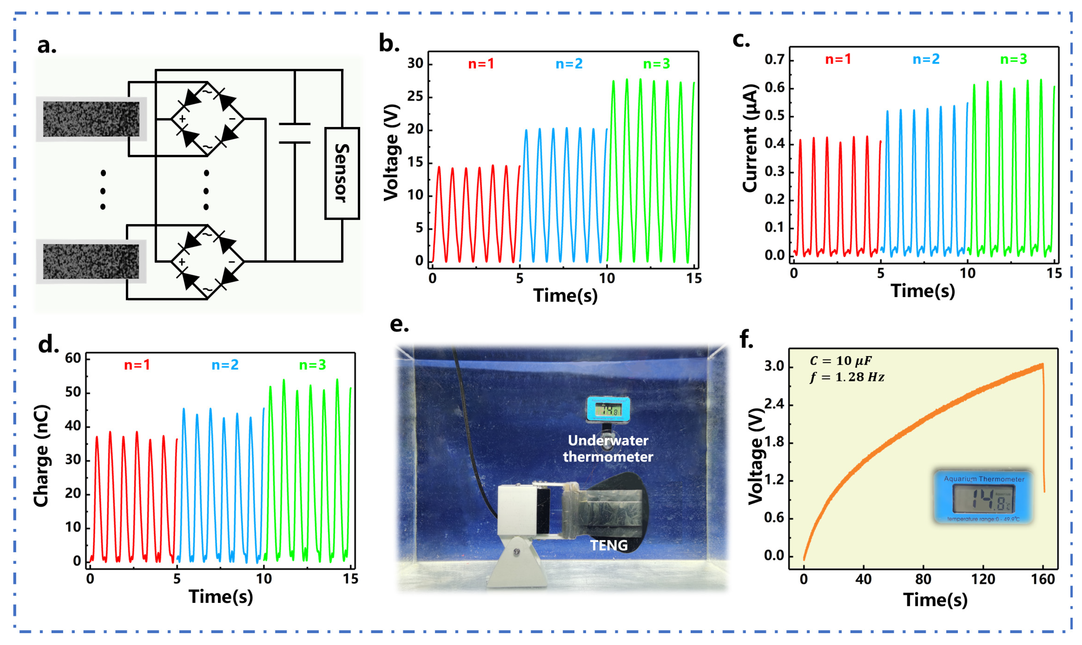
3. Results and Discussion

Figure 2a demonstrates the consistent resistance of the stretchable CB-silicone electrodes across bending and stretching states, after receiving micro-nano treatment. The resistance remains nearly constant across the three states, indicating that the electrode has excellent conductivity with stable output performance. Various electrode materials were tested to enhance the output of UF-TENG, including CB-silicone electrodes with rough surfaces, CB-silicone electrodes with smooth surfaces, ink electrodes, and Cu electrodes. The surface roughness of the textured electrode was determined to be around 100 µm using scanning electron microscopy, in contrast to the smooth electrode with a surface roughness of 8 µm. The graphite electrode employed in this study was created by applying ink onto an FEP membrane, and the copper electrode was fashioned using high-purity T2 copper foil. As shown in Figure 2b,c, the rough surface CB-silicone electrode in conjunction with silicone have superior performance under the same cyclic bending deformation conditions, characterized by the highest open circuit voltage and short circuit current. The observed phenomenon is attributed to the increased contact area between the rough CB-silicone electrode and the dielectric material, compared to the smoother CB-silicone electrode. This enlarged interface promotes a more extensive transfer of electrons, resulting in elevated output voltage and current. In contrast, the ink and Cu electrode materials establish direct and solid connections with the dielectric layer. Our custom-made CB-silicone electrode, on the other hand, establishes a softer interface with the dielectric layer, enabling a more thorough electron exchange. Consequently, the rough CB-silicone electrode generates higher output voltage and current compared to both ink and Cu electrodes [43,44].
Based on Maxwell’s displacement current, TENG operates in various modes. Specifically, the UF-TENG utilizes a free-standing mode TENG, depicted in Figure 2d. The physical model consists of conductive-dielectric materials, and the CB-silicone electrode plays a dual role as an electrode and a triboelectric material. Charges on its surface are bifurcated: one part arises from triboelectric electrification while the other is attributed to the charge transfer between the two electrodes during the electrostatic induction phase. According to the Gauss theorem, the relationship between the free-standing model of the conductive and dielectric model can be obtained:
V = Q S ε 0 d 0 ε 2 + x ( t ) + σ x ( t ) ε 0
Among them, S is the area of UF-TENG electrode material, d 0 is the thickness of CB-silicone electrode material, ε 2 is the dielectric constant of CB-silicone, ε 0 is the dielectric constant of the air layer, and σ is the charge density. Moreover, the transferred charge of the UF-TENG can be obtained from the following formula:
Q S C = 2 σ S x d 0 + g
Among them, σ is the charge density, S is the area of UF-TENG electrode material, x denotes the distance between the two triboelectric interaction layers, d 0 is the thickness of CB-silicone electrode material, and g represents the distance between the two electrodes.
To investigate the effects of the marine biological motion parameters and the marine environmental parameters on the output performance of UF-TENG. The UF-TENG is attached to the caudal fin-shaped silicone plate as shown in Figure 3a, which is driven by a servo motor. Here, a new medical bioadhesive, specifically a composite hydrogel bioadhesive, was employed for aquatic organisms, which exhibits excellent adhesion and fast curing speed and has been widely applied in aquatic biomedicine [45]. The test bench is shown in Figure S4, and the electronic components are shown in Figure S5. The initial connection of the UF-TENG is established with the circuit’s rectifier bridge. This component transforms the alternating current generated by the UF-TENG into a direct current that is appropriate for capacitive charging purposes. When the capacitor reaches its target voltage, the charge–discharge module activates. This action facilitates the provisioning of readily available electrical energy to the capacitor, serving as its load. The motor can vary the pitch angle ( α ), swing amplitude ( ω ), and swing frequency (f) to simulate different motion states of marine life. Figure 3a(i) represents the simulated motion state of marine life hovering, with a pitch angle of 0. Figure 3a(ii) illustrates the simulated motion state of marine life diving, with a pitch angle of α . Figure 3a(iii) depicts the simulated motion state of marine life floating up, with a pitch angle of − α . In order to explore the power generation performance of UF-TENG under different swing frequencies of marine life, Figure 3b illustrates the increase in the open-circuit voltage of the UF-TENG from 6 V to 12 V as the swing frequency rises from 0.8 Hz to 1.28 Hz while maintaining a pitch angle of 0° and a swing amplitude of π /3 rad. This is because as the swing amplitude increases, the contact area between the dielectric layer and the electrode layer of the UF-TENG also increases, leading to an increase in the transferred charge [37].
Subsequent tests assessed the short-circuit current produced over five distinct oscillation frequencies, as illustrated in Figure 3c. The short-circuit current increased from 0.1 μA to 0.35 μA as the frequency increased. The transferred charge exhibits a consistent trend (see Figure 3d), increasing with the frequency (f) from 0.8 Hz and peaking at 1.28 Hz with a value of 25 nC. The relevance of the output performance and swing amplitude is shown in Figure 3e–g, at 1.28 Hz frequency and a pitch angle of 0°. It is observed that the voltage increases as the amplitude ω increases from π /3 rad to 5 π /6 rad, and the voltage achieves a peak value of 14 V. Subsequent tests encompassed evaluations of the short-circuit current generated across five distinct oscillation frequencies (see Figure 3f). The short-circuit current increased from 0.35 μA to 0.41 μA as the swing amplitude increased. The transferred charge exhibits a consistent trend (see Figure 3g), increasing with the swing amplitude from π /3 rad and peaking at π /3 rad with a value of 38 nC.
In addition, the study simulates various motion postures of marine life by adjusting the pitch angle of the servo. The simulated postures include the initial state, floating state, and diving state. As shown in Figure 3h, the voltage remains relatively constant at different pitch angles due to the consistent swing frequency and amplitude. This stability suggests that the UF-TENG’s output remains unaffected by marine life’s floating and diving states when it is attached to their surface. In order to explore the influence of the marine environment on the output performance of UF-TENG, the output performance of the UF-TENG varying with the seawater temperature and salinity is investigated. As shown in Figure 3i, in the range of 0–20 °C [46], UF-TENG’s voltage exhibits an incremental trend with rising seawater temperature. The temperature of seawater is positively correlated with the voltage of UF-TENG. An analysis of TENG’s properties suggests that the phenomenon may be due to the acceleration of ion movement in the marine environment as the temperature rises, subsequently enhancing electrical resistance and conductivity.
Figure 3j shows the relationship between seawater salinity and UF-TENG output power. As seawater salinity increases, the output voltage of the UF-TENG gradually decreases. The output voltage of UF-TENG is negatively correlated with seawater salinity. This phenomenon is linked to the heightened conductivity and increased ion concentration of seawater resulting from elevated salinity levels [47]. The PTFE waterproof film within the UF-TENG makes direct contact with seawater, prompting an ion exchange with the ions present in the aqueous medium. Furthermore, PTFE interfaces directly with the electrodes in the UF-TENG. Despite PTFE’s limited impact on the electrodes, it facilitates the transfer of specific ions from the UF-TENG’s electrodes into the seawater, thereby diminishing the output performance of the UF-TENG. As seawater salinity increases, this ion transfer process is further accentuated. By studying the relationship between seawater temperature and salinity and the performance of UF-TENG, it was found that seawater temperature and salinity have different effects on UF-TENG. Therefore, although seawater temperature and salinity have a certain effect on UF-TENG, UF-TENG can still provide a stable power supply in various marine environments to ensure the durability of the sensors.
Figure 4a presents a series of 300 s charging experiments, the capacitor reaches 5 V, 3.8 V, 3 V, 2.2 V, and 1.8 V with a capacitance of 4.7 μF, 10 μF, 22 μF, 33 μF, and 47 μF at 1.28 Hz frequency, respectively. Figure 4a clearly demonstrates the inverse relationship between the charging rate and the capacitance. The charging rate is also influenced by the swing frequency, as shown in Figure 4b. During a 1.28 Hz frequency swing, a 10 μF capacitor could be charged up to 3.3 V in 150 s, and the charging process becomes faster with increasing frequency. Specifically, the charge within the capacitor has been completely discharged, leading to an output power of approximately 2.9 μW. Higher swing frequencies convey increased power, thereby elevating the charging rate. Figure 4c illustrates the plot of the output current and power of the UF-TENG under different load resistances. As the external load resistance increases, the output current decreases. At an external load of 70 MΩ, the peak power reaches 2.9 μW.
The study conducted in the previous section on the output characteristics of UF-TENG revealed a correlation between the voltage output of UF-TENG and the motion state of marine life as well as the marine environment. Due to its great mechanical responsiveness underwater, UF-TENG serves as a complementary tool for monitoring marine life behavior, supplementing the data from implantable electronic tags. As shown in Figure 4d, To determine the relationship between open circuit voltage and seawater temperature, the leave-one cross-validation was used. U = 0.1094 T + 12.9196, R 2 = 0.99863, where the correlation coefficient R 2 , indicated that the open circuit voltage and seawater temperature had an approximately linear relationship. This demonstrates the feasibility of using the voltage output of UF-TENG to obtain the seawater temperature along the swimming path of the monitored marine life.
Figure 4e shows that the linear relationship between the open circuit voltage and salinity could be expressed by U = −0.2374 S + 14.6167, R 2 = 0.9954. Therefore, UF-TENG enables the monitoring of the marine environment in which marine life swim. As shown in Figure 4f, the linear relationship between the swing amplitude of the marine life and the voltage output can be expressed by U = 0.8 θ + 10.75, R 2 = 0.9769, where the correlation coefficient R 2 indicated that the swing amplitude of the fishtail and the voltage output had an approximately linear relationship, with an error of less than 0.15% at a swing frequency of 1.28 Hz. Moreover, a minuscule error of 0.02% characterizes the linear association between swing frequency and voltage output at a swing amplitude of π /3 rad, as shown in Figure 4g.
The corresponding figure of the output voltage signal of UF-TENG and the posture of the fishtail is shown in Figure S6. Figure 4h illustrates the relationship between the voltage output of UF-TENG and the depth of marine life. As the depth increases, the pressure of the water rises, resulting in a reduction in the segregation distance. The experimental results also indicate a projected reduction in the device’s sensitivity with increasing depths, attributed to the influence of hydrostatic pressure. However, the operational continuity of the device is not compromised by hydrostatic pressure. This phenomenon persists due to the interaction of marine life’s oscillations, inducing bending in the UF-TENG, consequently causing relative motion between the silicone and CB-silicone electrodes. This relative motion plays a crucial role in generating the signal output. Finally, a durability test of the UF-TENG was conducted, as shown in Figure 4i. The device underwent a three-week water experiment under identical experimental conditions. The UF-TENG consistently maintained a stable output performance, with the voltage value remaining around 13 V throughout the three-week period. Consequently, this demonstrates that UF-TENG possesses excellent waterproof properties, which guarantee the longevity of UF-TENG.
Multiple studies have demonstrated that the overall electrical output of TENG can be enhanced by increasing the number of parallel-connected TENG units [36]. The investigation focused on the output of several parallel-connected UF-TENG units, with an increase in the unit number from 1 to 3. An experiment bench was established to study the output characteristics of parallel connected TENGs. Figure 5a illustrates the structural diagram of the integrated devices consisting of multiple UF-TENG units and their corresponding circuits. The experiment employed a KBP 310 model rectifier bridge, possessing a forward current capacity of 3.0 A and a reverse voltage tolerance of 1000 V. As shown in Figure 5b, at a frequency of 1.28 Hz and an amplitude of 5 π /6 rad, the UF-TENG gives an output voltage of 14 V. This output increases to 20 V and 27 V as the unit count rises to 2 and 3, respectively. Similarly, at a frequency of 1.28 Hz and an amplitude of 5 π /6 rad, the UF-TENG yields a short circuit current of 0.4 μA. As the number of units increases to 2 and 3 units, the short circuit current increases correspondingly to 0.5 μA and 0.6 μA, as shown in Figure 5c. There is a similar increase in the charge transferred. As the number of array units increases, the transferred charge increases from 38 nC to 55 nC, as shown in Figure 5d. These findings underscore that the UF-TENG’s output performance can be significantly optimized by enhancing the unit count. Supplementary Video S2 displays the process of powering a light emitting diode by three UF-TENG units, demonstrating its successful illumination after charging the 100 μF capacitor for 60 s. The attributes of the light-emitting diode is shown in Table S1. Figure 5e shows that an underwater thermometer is powered by a single UF-TENG unit. Figure 5f demonstrates the successful activation of the underwater thermometer after charging the 10 μF capacitor for 160 s under the charging frequency of 1.28 Hz. The underwater thermometer operated with a power supply voltage of 1.5 V, and its anticipated power consumption during operation was around 6 μW. Using the UF-TENG to supply power to sensors with higher power requirements results in an extended charging time, yet it effectively retains the ability to maintain the sensor’s intended functionality. Supplementary Video S3 showcases the process of powering the thermometer, demonstrating the continuous provision of electricity by the UF-TENG. Based on these results, UF-TENG demonstrates significant potential for powering sensors used in the monitoring of marine life. Additionally, the energy generated by the movement of marine life can be stored in an energy storage device to provide a stable energy supply for the sensors.

4. Materials and Methods

Figure 1f illustrates the fabrication process of the UF-TENG device. Initially, equal volumes of Ecoflex A and Ecoflex B were combined in a dry beaker. The mixture was then stirred clockwise for 20 min at room temperature to ensure complete mixing. Subsequently, the mixed silicone was poured into the centrifuge to obtain a silicone membrane. The silicone electrode was fully manufactured by placing it in a drying box at 40 °C for 6 h. This process was repeated to prepare another mixture of Ecoflex A and Ecoflex B, to which an equivalent volume of CB was added. This solution was stirred clockwise for one hour. The carbon black utilized in this study is manufactured by the TIMCAL company, designated as SUPER P LI grade, and possesses a particle size of 40 nm. Subsequently, pour the thoroughly mixed solution into the prepared molds and place it in a drying oven at 40 °C to obtain CB-silicone electrodes. The device physical diagram of UF-TENG is shown in Figure S1 and the view of the device cross-section is shown in Figure S2. The stress–strain curves of the CB-silicone electrodes are shown in Figure S3 of the Supplementary Material. The electrode material remains in the elastic stage within the stress range that the UF-TENG needs to withstand. This result demonstrates that the CB-silicone electrodes have high durability. The employed silicone, sourced from the Smooth-On Company in the U.S., is non-toxic, harmless, and biocompatible. The unique physical flexibility, stretchability, variable device size, elasticity, and biocompatibility of the UF-TENG device are attributed to its materials and manufacturing process. These properties and characteristics enable UF-TENG to exhibit high adaptability and compatibility with marine life. It can effectively convert changes in marine life posture into a bending and contraction of the device, thereby converting the resulting mechanical energy into electrical energy.

5. Conclusions

In this study, an underwater flexible triboelectric nanogenerator was designed to harvest the mechanical energy from marine lifes’ body-bending movements, providing a power source for implantable electronic tagging. Compared with lithium batteries, UF-TENG does not suffer from the problem of insufficient service life and the resulting need for battery replacement [20]. The UF-TENG is a free-standing mode device in which the contact area of two different materials (CB-silicone and silicone) with opposite triboelectric polarities is periodically changed, converting mechanical energy from marine lifes’ body-bending motions into electricity. In particular, the effects of marine biological motion parameters and marine environmental parameters on UF-TENG output performance were investigated, indicating that UF-TENG can adapt to various motion postures and different marine environments of marine life. A single UF-TENG can produce a peak output voltage of 14 V at 1.28 Hz and only requires 150 s to charge a 10 μF capacitor to 3.3 V. The energy density of the UF-TENG is 0.97 ×   10 3 (mW/cm2). The output voltage of UF-TENG can also serve as an indicator of the swing amplitude and frequency, complementing the information obtained from the electronic tag sensor. In addition, the total electrical output increases as the number of UF-TENG units connected in parallel increases (up to 3 units). The UF-TENG array (3 units) can produce a peak short-circuit current of 0.6 μA, while the transferred charge can reach 55 nC. The experimental results demonstrate that the UF-TENG array can provide sufficient and stable power for sensors. This implies that the implantable electronic tagging can receive constant power from a sufficient number of UF-TENG units. UF-TENG offers a novel approach to electronic power supply, and its biocompatibility enables potential applications in marine bioenergy harvesting. In the forthcoming research, endeavors will be focused on further improving the device’s output performance, enhancing its waterproof capabilities, and bolstering its resistance to biofouling.

Supplementary Materials

The following supporting information can be downloaded at: https://www.mdpi.com/article/10.3390/jmse11091766/s1, Figure S1: UF-TENG device physical diagram; Figure S2: Cross-section of UF-TENG; Figure S3: Tensile-strain curve of the CB-silicone electrode; Figure S4: Schematic of the experimental setup used; Figure S5: Circuits used in the experiment; Figure S6: The contrast relationship between UF-TENG signal and fishtail swing posture; Table S1: The attributes of the light-emitting diode; Video S1: Fludi simulation of UF-TENG; Video S2: UF-TENGs for powering a LED; Video S3: UF-TENGs for powering a thermometer.

Author Contributions

Conceptualization, P.X., M.X., T.D. and B.L.; methodology, X.X., H.W., B.L. and J.L.; software, B.L. and P.Z.; validation, Y.L. and L.G.; formal analysis, T.W., P.Z., Y.Z. and L.G.; investigation, J.L. and B.L.; resources, M.X. and T.D.; data curation, P.X. and B.L.; writing—original draft preparation, B.L. and P.X.; writing—review and editing, B.L.; supervision, T.D. and M.X.; project administration, P.S., H.W. and M.X.; funding acquisition, T.D., M.X. and P.S. All authors have read and agreed to the published version of the manuscript.

Funding

The work is supported by the Scientific Research Fund of the Educational Department of Liaoning Province (Grant No. LJKZ0055), Dalian Outstanding Young Scientific and Technological Talents Project (2021RJ11), the Open Fund of National Center for International Research of Subsea Engineering Technology and Equipment (No. 3132023354).

Institutional Review Board Statement

Not applicable.

Informed Consent Statement

Not applicable.

Data Availability Statement

Data are availability on request from the authors.

Conflicts of Interest

The authors declare no conflict of interest.

References

  1. Thorstad, E.B.; Rikardsen, A.H.; Alp, A.; ∅kland, F. The use of electronic tags in fish research–an overview of fish telemetry methods. Turk. J. Fish. Aquat. Sci. 2013, 13, 881–896. [Google Scholar]
  2. National Research Council. Understanding Marine Biodiversity; National Academies Press: Washington, DC, USA, 1995. [Google Scholar]
  3. Venkataraman, K.; Raghunathan, C. Coastal and marine biodiversity of India. In Marine Faunal Diversity in India; Elsevier: Amsterdam, The Netherlands, 2015; pp. 303–348. [Google Scholar]
  4. Sala, E.; Knowlton, N. Global marine biodiversity trends. Annu. Rev. Environ. Resour. 2006, 31, 93–122. [Google Scholar] [CrossRef]
  5. Grigg, R.W. Effects of sewage discharge, fishing pressure and habitat complexity on coral ecosystems and reef fishes in Hawaii. Mar. Ecol. Prog. Ser. Oldendorf 1994, 103, 25–34. [Google Scholar] [CrossRef]
  6. Ford, A.K.; Van Hoytema, N.; Moore, B.R.; Pandihau, L.; Wild, C.; Ferse, S.C. High sedimentary oxygen consumption indicates that sewage input from small islands drives benthic community shifts on overfished reefs. Environ. Conserv. 2017, 44, 405–411. [Google Scholar] [CrossRef]
  7. Marshall, R.C.; Fisher, J.A.; Gatti, P.; Carruthers, E.H.; Robert, D.; Le Bris, A. Combining electronic tag data and fish harvesters’ knowledge to identify ocean management concerns. Mar. Policy 2023, 147, 105393. [Google Scholar] [CrossRef]
  8. Lundquist, C.J.; Granek, E.F. Strategies for successful marine conservation: Integrating socioeconomic, political, and scientific factors. Conserv. Biol. 2005, 19, 1771–1778. [Google Scholar] [CrossRef]
  9. Thaxter, C.B.; Ross-Smith, V.H.; Clark, J.A.; Clark, N.A.; Conway, G.J.; Masden, E.A.; Wade, H.M.; Leat, E.H.; Gear, S.C.; Marsh, M.; et al. Contrasting effects of GPS device and harness attachment on adult survival of Lesser Black-backed Gulls Larus fuscus and Great Skuas Stercorarius skua. Ibis 2016, 158, 279–290. [Google Scholar] [CrossRef]
  10. MacRae, A.M.; Makowska, I.J.; Fraser, D. Initial evaluation of facial expressions and behaviours of harbour seal pups (Phoca vitulina) in response to tagging and microchipping. Appl. Anim. Behav. Sci. 2018, 205, 167–174. [Google Scholar] [CrossRef]
  11. Hays, G.C.; Rattray, A.; Esteban, N. Addressing tagging location bias to assess space use by marine animals. J. Appl. Ecol. 2020, 57, 1981–1987. [Google Scholar] [CrossRef]
  12. Hammerschlag, N.; Cooke, S.J.; Gallagher, A.J.; Godley, B.J. Considering the fate of electronic tags: Interactions with stakeholders and user responsibility when encountering tagged aquatic animals. Methods Ecol. Evol. 2014, 5, 1147–1153. [Google Scholar] [CrossRef]
  13. Bacopoulos, P.; Lambert, J.D.; Hertz, M.; Montoya, L.; Smith, T. Field and model study to define baseline conditions of beached oil tar balls along Florida’s First Coast. J. Mar. Sci. Eng. 2014, 2, 160–170. [Google Scholar] [CrossRef]
  14. Maniscalco, R.; Forzese, M.; Barbagallo, V.; Borzì, L.; D’Andrea, N.M.; Distefano, S.; Giustolisi, C.; Nádudvari, Á.; Pellegrino, A.G.; Foresi, L.M.; et al. Toward an Astrochronology-Based Age-Model for a Messinian Pre-Evaporitic Succession: The Example of Torrente Vaccarizzo Section in Sicily (Italy). J. Mar. Sci. Eng. 2023, 11, 915. [Google Scholar] [CrossRef]
  15. Todd Jones, T.; Van Houtan, K.S.; Bostrom, B.L.; Ostafichuk, P.; Mikkelsen, J.; Tezcan, E.; Carey, M.; Imlach, B.; Seminoff, J.A. Calculating the ecological impacts of animal-borne instruments on aquatic organisms. Methods Ecol. Evol. 2013, 4, 1178–1186. [Google Scholar] [CrossRef]
  16. Cooke, S.J.; Woodley, C.M.; Brad Eppard, M.; Brown, R.S.; Nielsen, J.L. Advancing the surgical implantation of electronic tags in fish: A gap analysis and research agenda based on a review of trends in intracoelomic tagging effects studies. Rev. Fish Biol. Fish. 2011, 21, 127–151. [Google Scholar] [CrossRef]
  17. Mulcahy, D.M. Antibiotic use during the intracoelomic implantation of electronic tags into fish. Rev. Fish Biol. Fish. 2011, 21, 83–96. [Google Scholar] [CrossRef]
  18. Block, B.A.; Jonsen, I.D.; Jorgensen, S.J.; Winship, A.J.; Shaffer, S.A.; Bograd, S.J.; Hazen, E.L.; Foley, D.G.; Breed, G.; Harrison, A.L.; et al. Tracking apex marine predator movements in a dynamic ocean. Nature 2011, 475, 86–90. [Google Scholar] [CrossRef]
  19. Li, H.; Lu, J.; Myjak, M.J.; Liss, S.A.; Brown, R.S.; Tian, C.; Deng, Z.D. An implantable biomechanical energy harvester for animal monitoring devices. Nano Energy 2022, 98, 107290. [Google Scholar] [CrossRef]
  20. Zeng, L.; Hu, Y.; Lu, C.; Pan, G.; Li, M. Arrhenius Equation-Based Model to Predict Lithium-Ions Batteries’ Performance. J. Mar. Sci. Eng. 2022, 10, 1553. [Google Scholar] [CrossRef]
  21. Walker, K.A.; Trites, A.W.; Haulena, M.; Weary, D.M. A review of the effects of different marking and tagging techniques on marine mammals. Wildl. Res. 2011, 39, 15–30. [Google Scholar] [CrossRef]
  22. Magle, S.B.; Hunt, V.M.; Vernon, M.; Crooks, K.R. Urban wildlife research: Past, present, and future. Biol. Conserv. 2012, 155, 23–32. [Google Scholar] [CrossRef]
  23. Yang, Y.; Lu, J.; Pflugrath, B.D.; Li, H.; Martinez, J.J.; Regmi, S.; Wu, B.; Xiao, J.; Deng, Z.D. Lab-on-a-fish: Wireless, miniaturized, fully integrated, implantable biotelemetric tag for real-time in vivo monitoring of aquatic animals. IEEE Internet Things J. 2021, 9, 10751–10762. [Google Scholar] [CrossRef]
  24. Fan, F.R.; Tian, Z.Q.; Wang, Z.L. Flexible triboelectric generator. Nano Energy 2012, 1, 328–334. [Google Scholar] [CrossRef]
  25. Yan, J.; Liu, M.; Jeong, Y.G.; Kang, W.; Li, L.; Zhao, Y.; Deng, N.; Cheng, B.; Yang, G. Performance enhancements in poly (vinylidene fluoride)-based piezoelectric nanogenerators for efficient energy harvesting. Nano Energy 2019, 56, 662–692. [Google Scholar] [CrossRef]
  26. Sun, J.; Guo, H.; Ribera, J.; Wu, C.; Tu, K.; Binelli, M.; Panzarasa, G.; Schwarze, F.W.; Wang, Z.L.; Burgert, I. Sustainable and biodegradable wood sponge piezoelectric nanogenerator for sensing and energy harvesting applications. ACS Nano 2020, 14, 14665–14674. [Google Scholar] [CrossRef]
  27. Noll, M.U.; Lentz, L.; von Wagner, U. On the discretization of a bistable cantilever beam with application to energy harvesting. Facta Univ. Ser. Mech. Eng. 2019, 17, 125–139. [Google Scholar] [CrossRef]
  28. Marinković, D.; Rama, G.; Zehn, M. Abaqus implementation of a corotational piezoelectric 3-node shell element with drilling degree of freedom. Facta Univ. Ser. Mech. Eng. 2019, 17, 269–283. [Google Scholar] [CrossRef]
  29. Nguyen, X.H.; Nguyen, H.A. Investigation of influences of fabrication tolerances on operational characteristics of piezo-actuated stick-slip micro-drives. Facta Univ. Ser. Mech. Eng. 2022, 20, 109–126. [Google Scholar] [CrossRef]
  30. Kachapi, S.H.H. Nonlinear vibration response of piezoelectric nanosensor: Influences of surface/interface effects. Facta Univ. Ser. Mech. Eng. 2023, 21, 259–272. [Google Scholar]
  31. Kim, W.G.; Kim, D.W.; Tcho, I.W.; Kim, J.K.; Kim, M.S.; Choi, Y.K. Triboelectric nanogenerator: Structure, mechanism, and applications. Acs Nano 2021, 15, 258–287. [Google Scholar] [CrossRef]
  32. Niu, S.; Wang, Z.L. Theoretical systems of triboelectric nanogenerators. Nano Energy 2015, 14, 161–192. [Google Scholar] [CrossRef]
  33. Cheng, T.; Gao, Q.; Wang, Z.L. The current development and future outlook of triboelectric nanogenerators: A survey of literature. Adv. Mater. Technol. 2019, 4, 1800588. [Google Scholar] [CrossRef]
  34. So, M.Y.; Xu, B.; Li, Z.; Lai, C.L.; Jiang, C. Flexible corrugated triboelectric nanogenerators for efficient biomechanical energy harvesting and human motion monitoring. Nano Energy 2023, 106, 108033. [Google Scholar] [CrossRef]
  35. Wang, X.; Liu, J.; Wang, S.; Zheng, J.; Guan, T.; Liu, X.; Wang, T.; Chen, T.; Wang, H.; Xie, G.; et al. A Self-powered Triboelectric Coral-Like Sensor Integrated Buoy for Irregular and Ultra-Low Frequency Ocean Wave Monitoring. Adv. Mater. Technol. 2022, 7, 2101098. [Google Scholar] [CrossRef]
  36. Wang, H.; Fan, Z.; Zhao, T.; Dong, J.; Wang, S.; Wang, Y.; Xiao, X.; Liu, C.; Pan, X.; Zhao, Y.; et al. Sandwich-like triboelectric nanogenerators integrated self-powered buoy for navigation safety. Nano Energy 2021, 84, 105920. [Google Scholar] [CrossRef]
  37. Xu, P.; Liu, J.; Liu, X.; Wang, X.; Zheng, J.; Wang, S.; Chen, T.; Wang, H.; Wang, C.; Fu, X.; et al. A bio-inspired and self-powered triboelectric tactile sensor for underwater vehicle perception. NPJ Flex. Electron. 2022, 6, 25. [Google Scholar] [CrossRef]
  38. Wang, X.; Shi, Y.; Yang, P.; Tao, X.; Li, S.; Lei, R.; Liu, Z.; Wang, Z.L.; Chen, X. Fish-Wearable Data Snooping Platform for Underwater Energy Harvesting and Fish Behavior Monitoring. Small 2022, 18, 2107232. [Google Scholar] [CrossRef]
  39. Wang, Y.; Liu, X.; Chen, T.; Wang, H.; Zhu, C.; Yu, H.; Song, L.; Pan, X.; Mi, J.; Lee, C.; et al. An underwater flag-like triboelectric nanogenerator for harvesting ocean current energy under extremely low velocity condition. Nano Energy 2021, 90, 106503. [Google Scholar] [CrossRef]
  40. Du, T.; Dong, F.; Zhu, M.; Xi, Z.; Li, F.; Zou, Y.; Sun, P.; Xu, M. Self-Powered and Robust Marine Exhaust Gas Flow Sensor Based on Bearing Type Triboelectric Nanogenerator. J. Mar. Sci. Eng. 2022, 10, 1416. [Google Scholar] [CrossRef]
  41. Xiao, X.; Wang, Q.; Yao, B.; Guo, L.; Zhu, C.; Zhao, C.; Liu, L.; Xu, M. Research on Low-Frequency Vibration Monitoring Sensor Based on a Cantilever-Beam-Structured Triboelectric Nanogenerator. J. Mar. Sci. Eng. 2023, 11, 838. [Google Scholar] [CrossRef]
  42. Feng, S.; Zhong, Z.; Wang, Y.; Xing, W.; Drioli, E. Progress and perspectives in PTFE membrane: Preparation, modification, and applications. J. Membr. Sci. 2018, 549, 332–349. [Google Scholar] [CrossRef]
  43. Zhou, Q.; Kim, J.N.; Han, K.W.; Oh, S.W.; Umrao, S.; Chae, E.J.; Oh, I.K. Integrated dielectric-electrode layer for triboelectric nanogenerator based on Cu nanowire-Mesh hybrid electrode. Nano Energy 2019, 59, 120–128. [Google Scholar] [CrossRef]
  44. Bui, V.T.; Oh, J.H.; Kim, J.N.; Zhou, Q.; Oh, I.K. Nest-inspired nanosponge-Cu woven mesh hybrid for ultrastable and high-power triboelectric nanogenerator. Nano Energy 2020, 71, 104561. [Google Scholar] [CrossRef]
  45. Tavafoghi, M.; Sheikhi, A.; Tutar, R.; Jahangiry, J.; Baidya, A.; Haghniaz, R.; Khademhosseini, A. Engineering tough, injectable, naturally derived, bioadhesive composite hydrogels. Adv. Healthc. Mater. 2020, 9, 1901722. [Google Scholar] [CrossRef] [PubMed]
  46. Rohling, E.; Foster, G.L.; Grant, K.; Marino, G.; Roberts, A.; Tamisiea, M.E.; Williams, F. Sea-level and deep-sea-temperature variability over the past 5.3 million years. Nature 2014, 508, 477–482. [Google Scholar] [CrossRef]
  47. Park, S.; Ligaray, M.; Kim, Y.; Chon, K.; Son, M.; Cho, K.H. Investigating the influence of catholyte salinity on seawater battery desalination. Desalination 2021, 506, 115018. [Google Scholar] [CrossRef]
Figure 1. Structural Design and working mechanism of the UF-TENG: (a) Application of the UF-TENG harvesting energy. (b) The structure diagram and micro-nano structure of UF-TENG. (c) The working mechanism of the UF-TENG. (d) The potential simulation of UF-TENG. (e) Fluid simulation of UF-TENG. (f) Process flow of the CB-silicone electrode and silicone–rubber membrane.
Jmse 11 01766 g001
Figure 2. Performance testing of the stretchable UF-TENG materials: (a) The electrical resistance of the electrodes membrane or membrane under various deformations. (b) The output current of UF-TENG with the different electrode materials at the same frequency. (c) The output voltage of UF-TENG with the different electrode materials at the same frequency. (d) Coordinate system of UF-TENG.
Jmse 11 01766 g002
Figure 3. Output performance of a single unit of UF-TENG measured underwater: (a) Simulation of different swimming styles of fish. (b) Open-circuit voltage, (c) short-circuit current and (d) transferred charges measured under different frequencies. (e) Open-circuit voltage measured, (f) short-circuit current measured and (g) transferred charges measured under different amplitudes. (h) The open-circuit voltage of a single unit of UF-TENG at different pitch angles under different amplitudes. (i) Voltage measured under different temperatures. (j) Voltage measured under different salinities.
Jmse 11 01766 g003
Figure 4. The voltage output of UF-TENG: (a) The voltage of various capacitors charging by UF-TENG under different capacitance. (b) The voltage of various capacitors charging by UF-TENG under different frequencies. (c) Resistance dependency of the output voltage and peak power of the UF-TENG unit. (d) Fitting linear relationship between voltage and temperature. (e) Fitting linear relationship between voltage and salinity. (f) Fitting linear relationship between voltage and amplitude. (g) Fitting linear relationship between voltage and frequency. (h) Relationship between voltage and depth. (i) Durability of UF-TENG.
Jmse 11 01766 g004
Figure 5. The output performance of UF-TENG with different units measured underwater: (a) The corresponding power management circuit diagram of UF-TENG. (b) Open-circuit voltage with different units. (c) Short-circuit current with different units. (d) Transferred charges of UF-TENG with different units. (e,f) Applications of UF-TENG.
Jmse 11 01766 g005
Disclaimer/Publisher’s Note: The statements, opinions and data contained in all publications are solely those of the individual author(s) and contributor(s) and not of MDPI and/or the editor(s). MDPI and/or the editor(s) disclaim responsibility for any injury to people or property resulting from any ideas, methods, instructions or products referred to in the content.

