
Numerical Investigation of the Influence of a Splitter Plate on Mixing Transfer in the Ducts of a Rotary Energy Recovery Device


Abstract
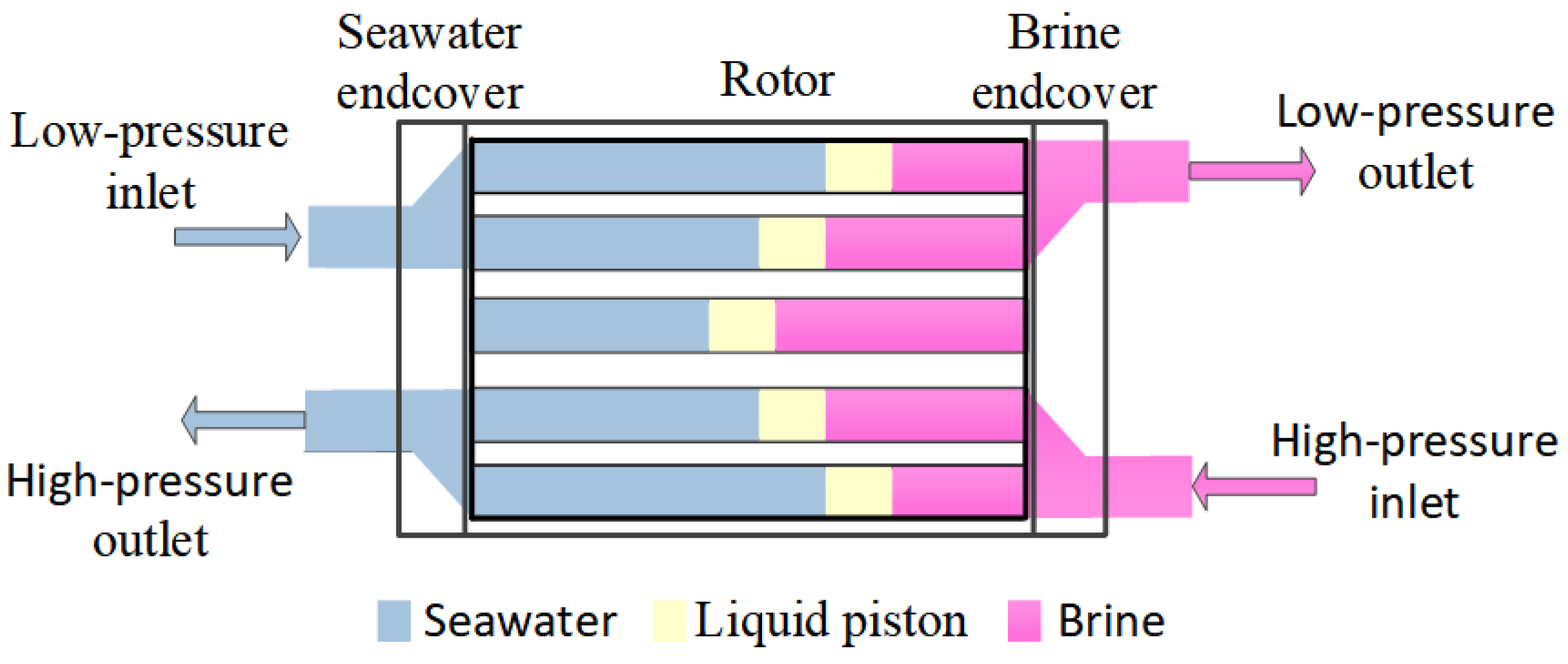
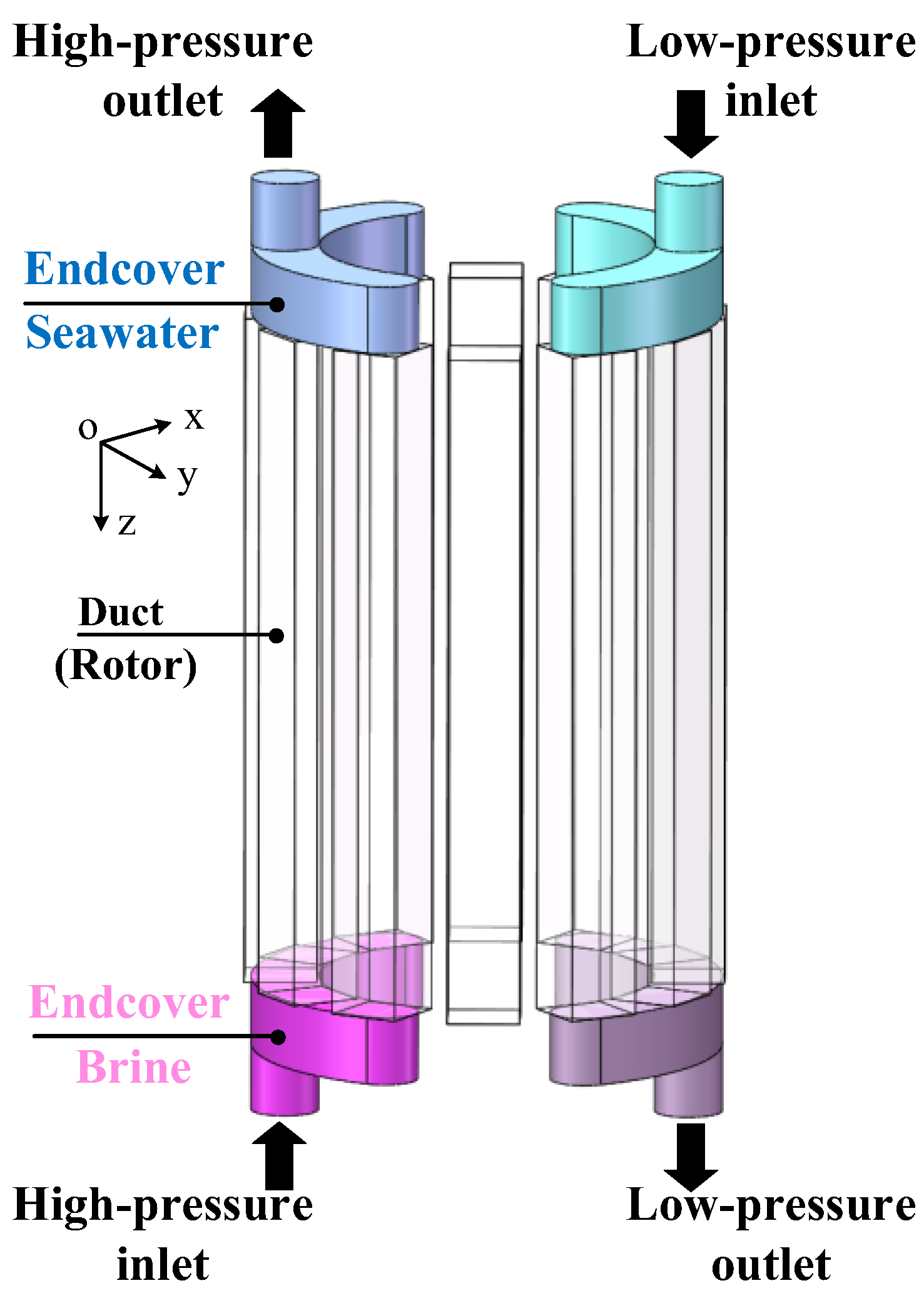
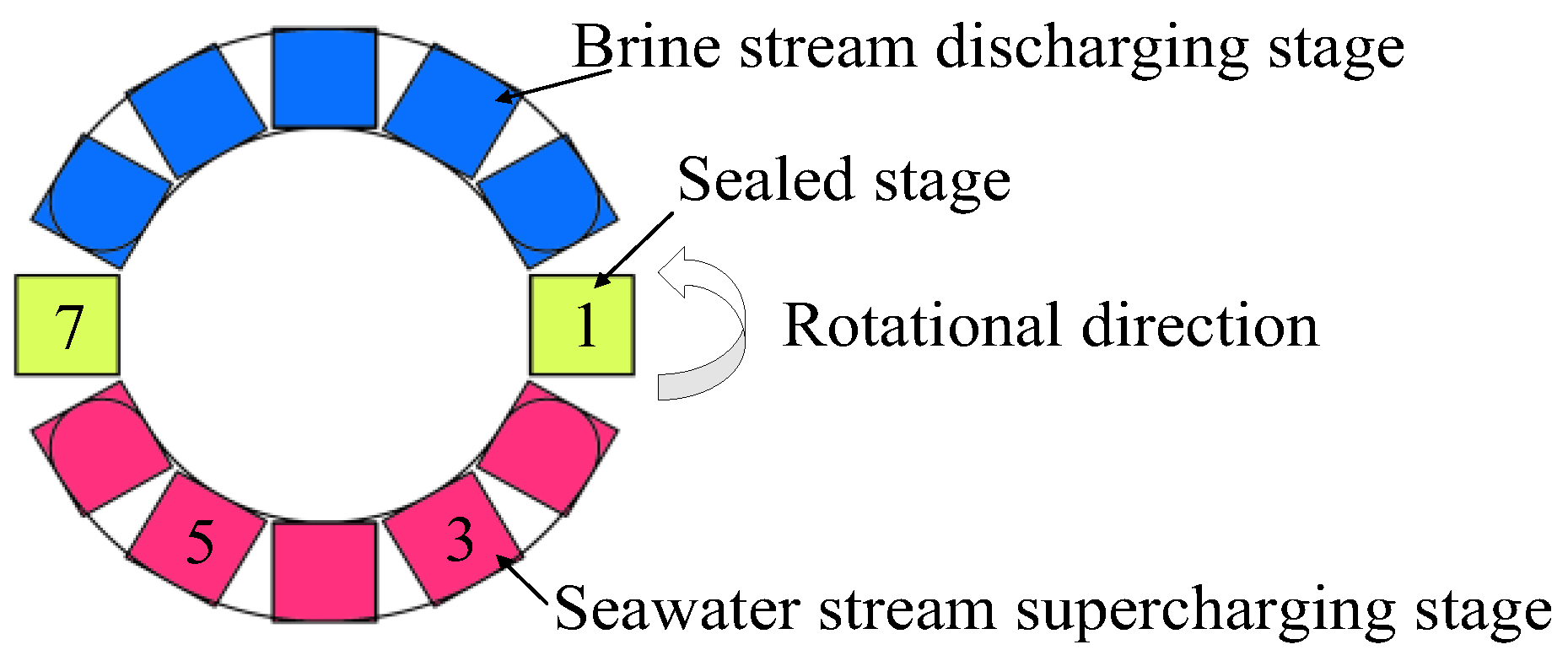
:1. Introduction

| Reference | Volumetric Mixing Rate | Method |
|---|---|---|
| Zhou et al. [18] | 3~16% | Adjusting operational parameters |
| Liu et al. [19] | 3~6% | Adjusting operational parameters |
| Xu et al. [20] | 2~10% | Adjusting operational parameters |
| Wu et al. [21] | 2~9% | Endcover with groove-textured surface |
| Xu et al. [22] | 2~9% | Adjusting operational parameters |
| Yin et al. [23] | 2~6% | Adjusting operational and structural parameters |
| Cao et al. [24] | 1–4% | Endcover with extended angle |
2. Numerical Methods
3. Results
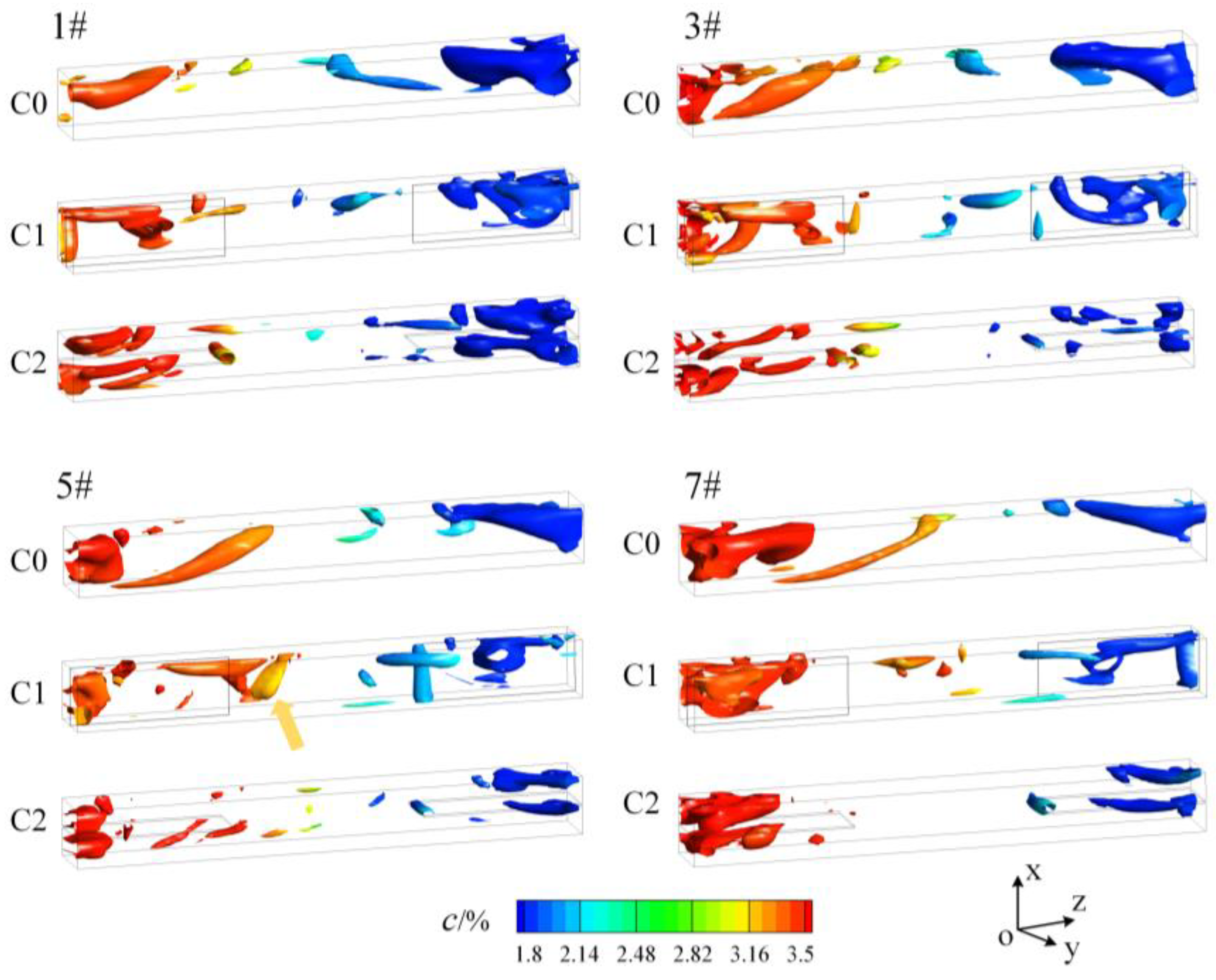
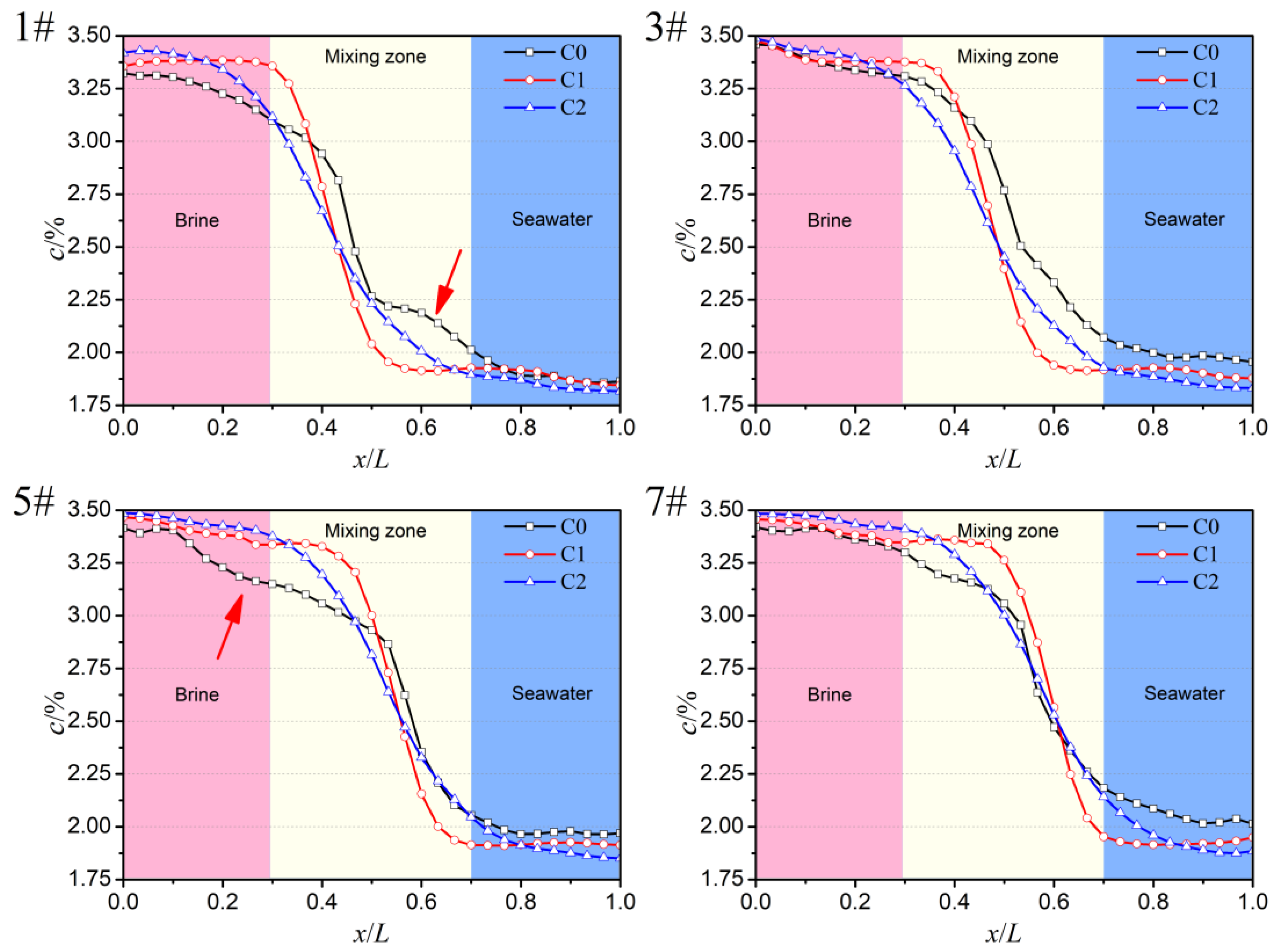
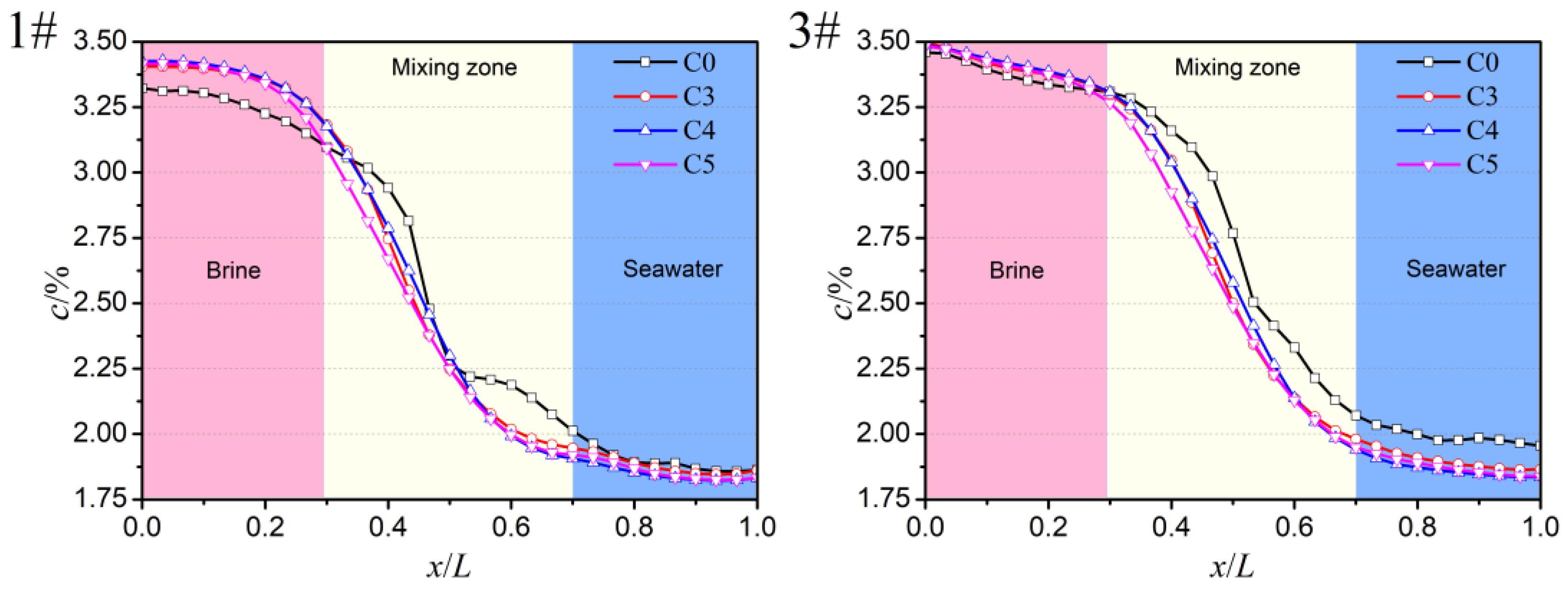
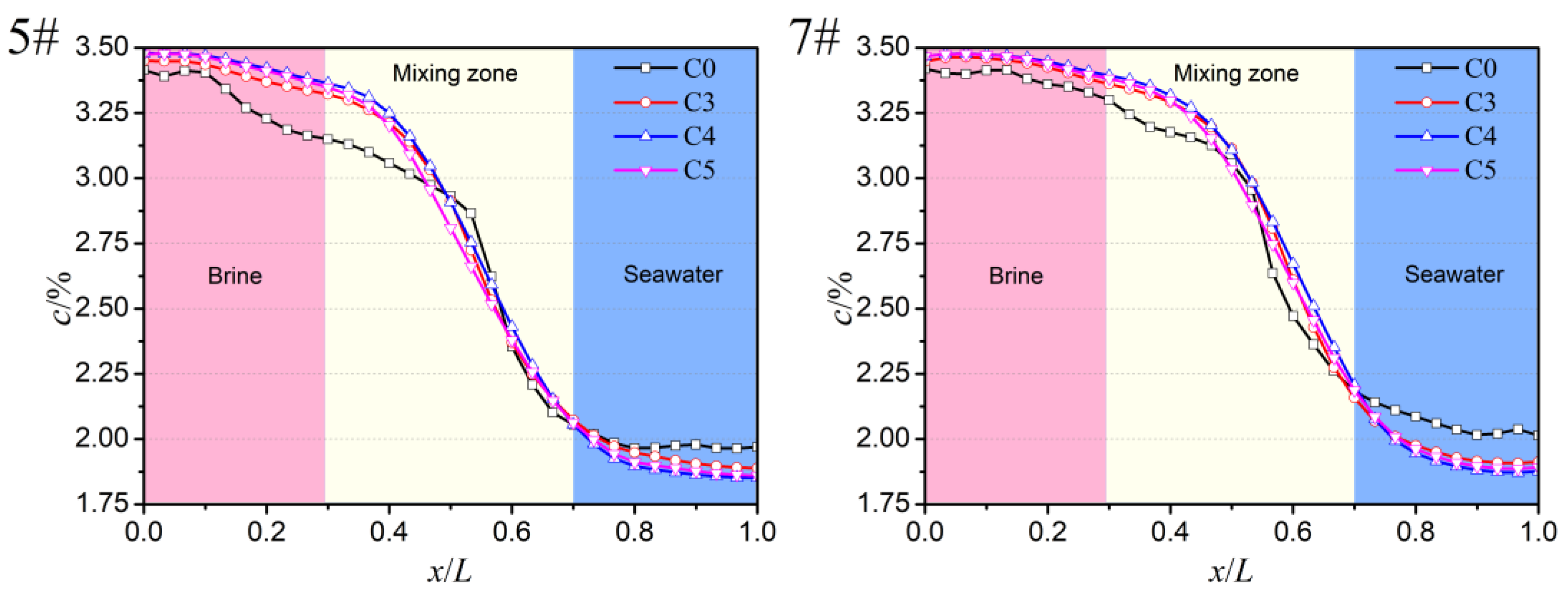
3.1. Results of Volumetric Mixing Rate
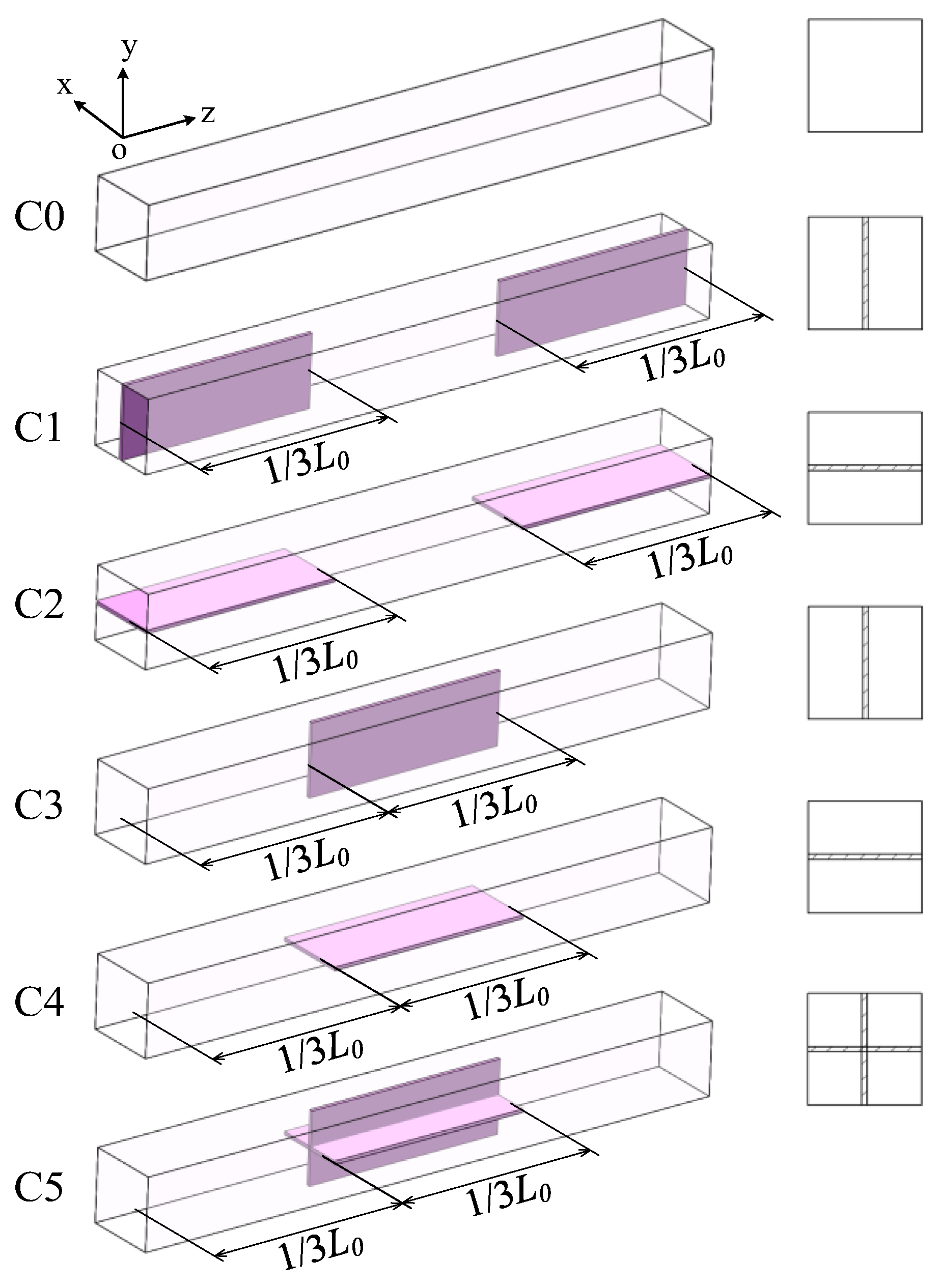
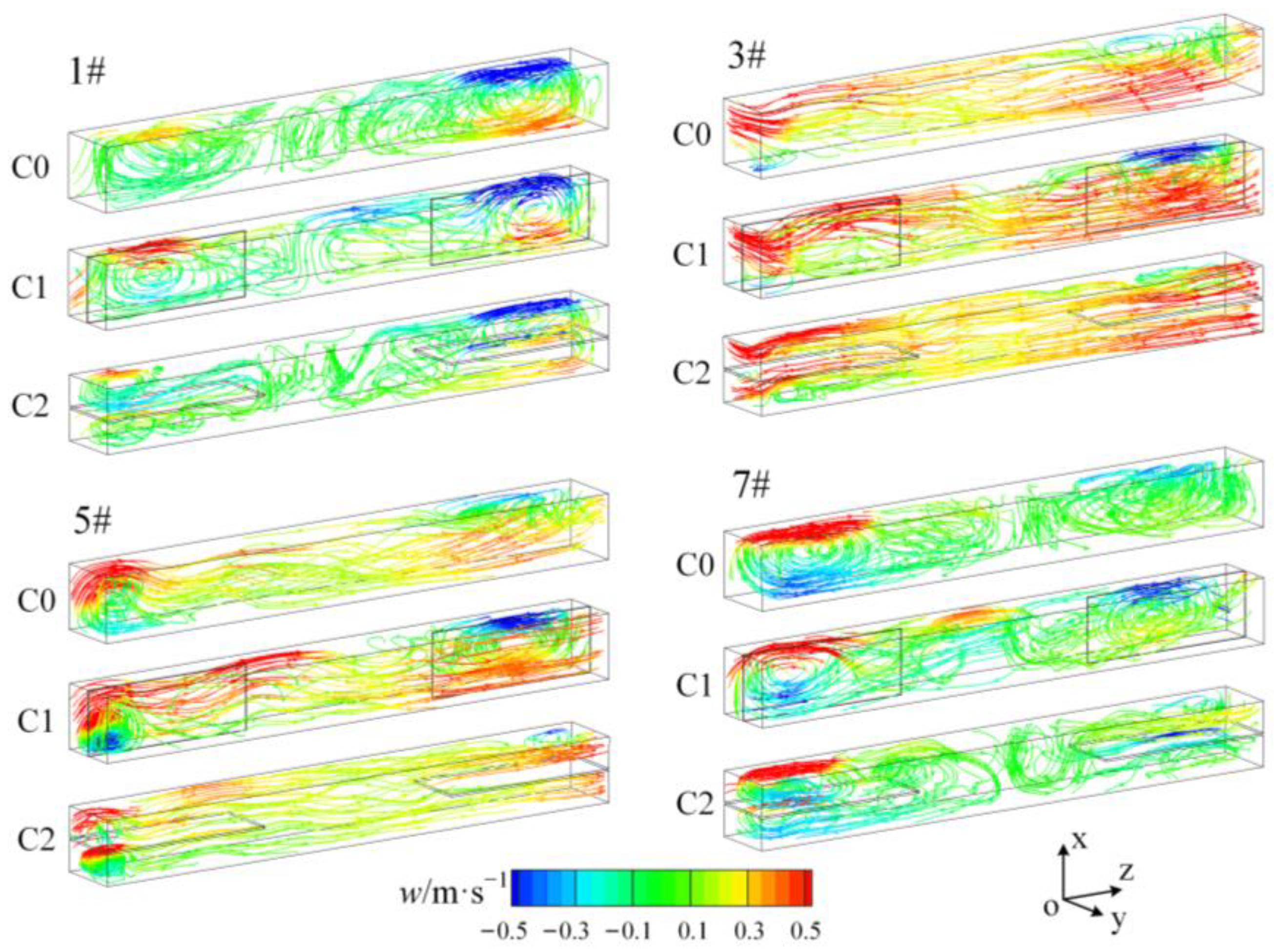
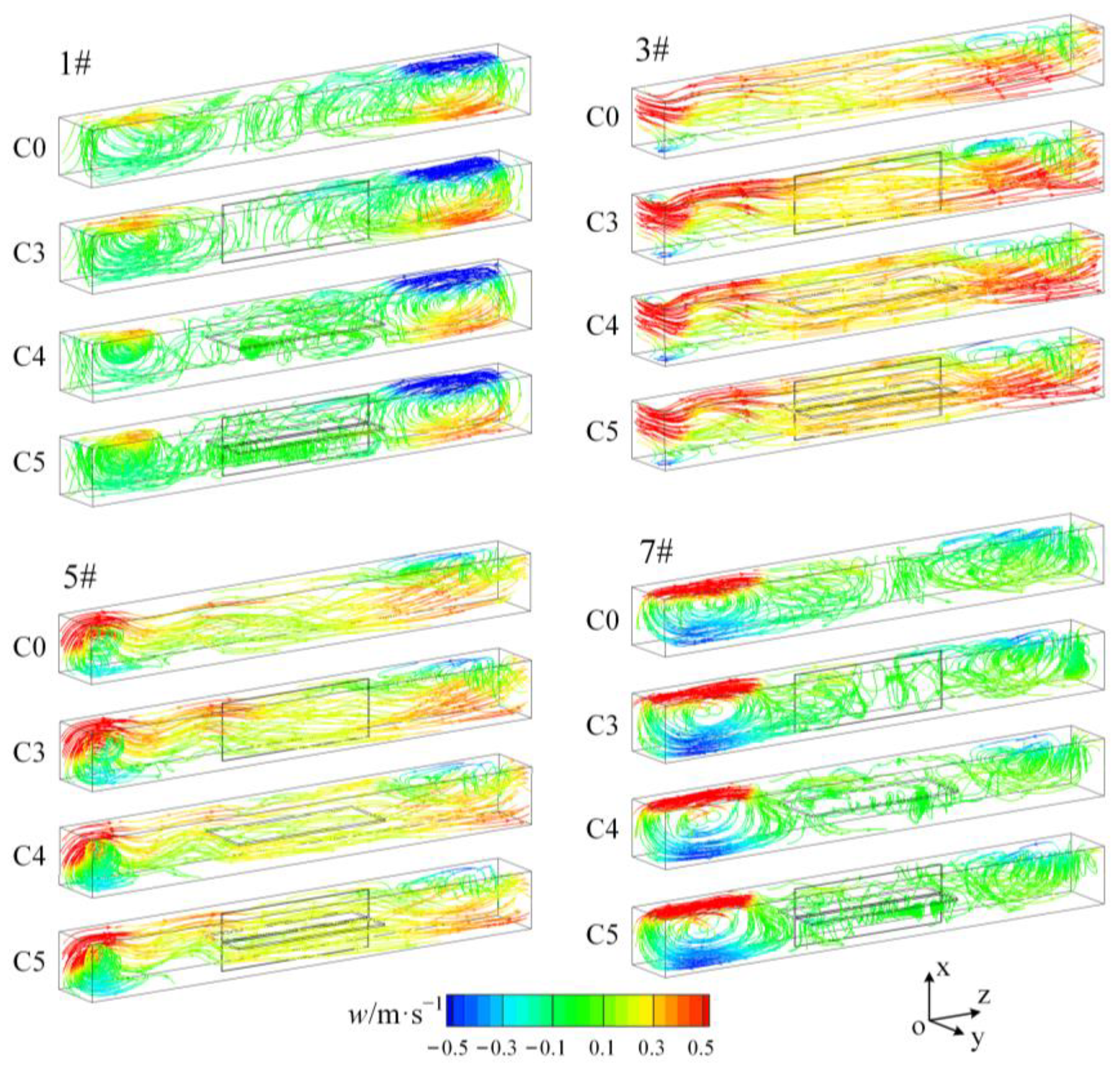
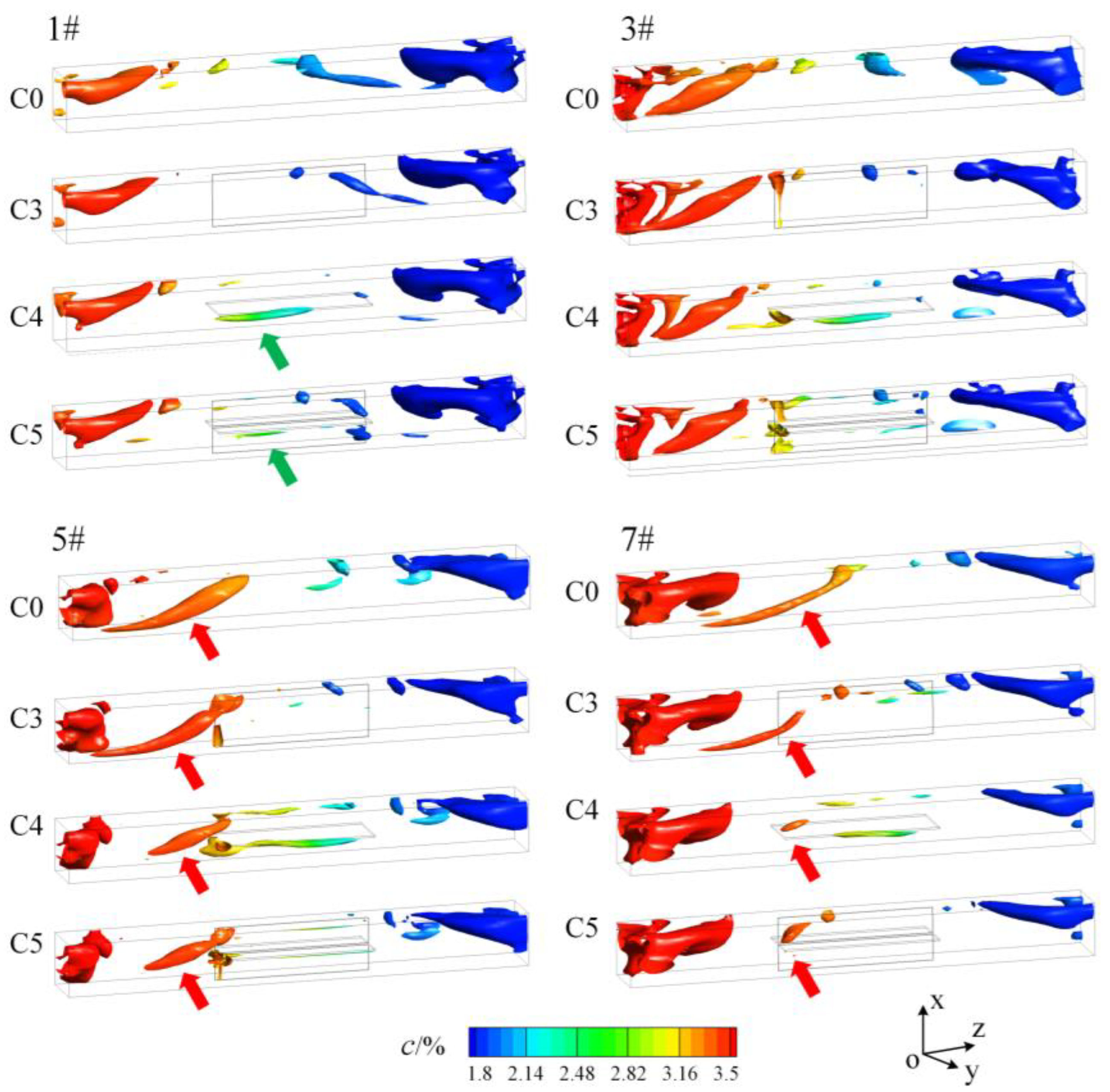
3.2. The Control Effect of Splitter Plates on the “Entrance Effect”
3.3. The Control Effect of Splitter Plates on the Liquid Piston
4. Conclusions
- (1)
- Flow structure and vortex formation control: Effective suppression of swirling flows at the entrance was achieved when horizontal splitter plates were positioned at the duct inlet (as seen in experimental case C2). Moreover, the control of flow-induced vortices generated by the “entrance effect” was efficiently executed by splitter plates positioned at the center of the duct (as seen in experimental cases C4 and C5), preventing their propagation into the central duct region.
- (2)
- Salinity distribution and mass transfer: By efficiently suppressing the ‘entrance effect’ and flow-induced vortices, as observed in experimental case C2 and experimental cases C4 and C5, respectively, these configurations resulted in decreased flow intensity and the establishment of a more uniform salinity distribution. Consequently, the mass transfer between brine and seawater streams was significantly minimized.
- (3)
- Effect of splitter plates on volumetric mixing rate: The utilization of splitter plates consistently reduced the volumetric mixing rate across all experimental cases compared to the control case. This reduction was most notable when utilizing cross-spread splitter plates positioned at the center of the duct, as evidenced in experimental case C5, where a remarkable 57% decrease in volumetric mixing rate was achieved compared to the control case.
Author Contributions
Funding
Institutional Review Board Statement
Informed Consent Statement
Data Availability Statement
Acknowledgments
Conflicts of Interest
References
- Tawalbeh, M.; Qalyoubi, L.; Al-Othman, A.; Qasim, M.; Shirazi, M. Insights on the development of enhanced antifouling reverse osmosis membranes: Industrial applications and challenges. Desalination 2023, 553, 116460. [Google Scholar] [CrossRef]
- Zinatloo-Ajabshir, S.; Morassaei, M.S.; Salavati-Niasari, M. Eco-friendly synthesis of Nd2Sn2O7–based nanostructure materials using grape juice as green fuel as photocatalyst for the degradation of erythrosine. Compos. Part B Eng. 2019, 167, 643–653. [Google Scholar] [CrossRef]
- Esfahani, M.H.; Zinatloo-Ajabshir, S.; Naji, H.; Marjerrison, C.A.; Greedan, J.E.; Behzad, M. Structural characterization, phase analysis and electrochemical hydrogen storage studies on new pyrochlore SmRETi2O7 (RE = Dy, Ho, and Yb) microstructures. Ceram. Int. 2023, 49, 253–263. [Google Scholar] [CrossRef]
- Caldera, U.; Breyer, C. Afforesting arid land with renewable electricity and desalination to mitigate climate change. Nat. Sustain. 2023, 6, 526–538. [Google Scholar] [CrossRef]
- Kadaj, E.; Bosleman, R. Chapter 11—Energy Recovery Devices in Membrane Desalination Processes. In Renewable Energy Powered Desalination Handbook; Gude, V.G., Ed.; Butterworth-Heinemann: Oxford, UK, 2018; pp. 415–444. [Google Scholar]
- Ayaz, M.; Namazi, M.A.; Din, M.A.; Ershath, M.I.M.; Mansour, A.; Aggoune, e.-H.M. Sustainable seawater desalination: Current status, environmental implications and future expectations. Desalination 2022, 540, 116022. [Google Scholar] [CrossRef]
- Nassrullah, H.; Anis, S.F.; Hashaikeh, R.; Hilal, N. Energy for desalination: A state-of-the-art review. Desalination 2020, 491, 114569. [Google Scholar] [CrossRef]
- Wang, C.; Meng, P.; Wang, S.; Song, D.; Xiao, Y.; Zhang, Y.; Ma, Q.; Liu, S.; Wang, K.; Zhang, Y. Comparison of two types of energy recovery devices: Pressure exchanger and turbine in an island desalination project case. Desalination 2022, 533, 115752. [Google Scholar] [CrossRef]
- Stover, R.L. Seawater reverse osmosis with isobaric energy recovery devices. Desalination 2007, 203, 168–175. [Google Scholar] [CrossRef]
- Bross, S.; Kochanowski, W. SWRO core hydraulic system: Extension of the SalTec DT to higher flows and lower energy consumption. Desalination 2007, 203, 160–167. [Google Scholar] [CrossRef]
- Cameron, I.B.; Clemente, R.B. SWRO with ERI’s PX Pressure Exchanger device—A global survey. Desalination 2008, 221, 136–142. [Google Scholar] [CrossRef]
- Stover, R.; Fernandez, A.O.; Galtes, J. Permeate Recovery Rate Optimization at the Alicante Spain SWRO Plant. In Proceedings of the International Desalination Association World Congress, Dubai, United Arab Emirates, 7–12 November 2009. [Google Scholar]
- Schneider, B. Desalination and the Environment Selection, operation and control of a work exchanger energy recovery system based on the Singapore project. Desalination 2005, 184, 197–210. [Google Scholar] [CrossRef]
- Goto, A.; Shinoda, M.; Takemura, T. Mixing Control in an Isobaric Energy Recovery Device of Seawater Reverse Osmosis Desalination System. In ASME 2017 Fluids Engineering Division Summer Meeting; American Society of Mechanical Engineers: New York, NY, USA, 2017; p. V01BT08A003. [Google Scholar]
- Liu, K.; Deng, J.; Ye, F. Numerical simulation of flow structures in a rotary type energy recovery device. Desalination 2019, 449, 101–110. [Google Scholar] [CrossRef]
- Zhao, M. A review of recent studies on the control of vortex-induced vibration of circular cylinders. Ocean Eng. 2023, 285, 115389. [Google Scholar] [CrossRef]
- Islam, S.; Rahman, H.; Abbasi, W.; Noreen, U.; Khan, A. Suppression of fluid force on flow past a square cylinder with a detached flat plate at low Reynolds number for various spacing ratios. J. Mech. Sci. Technol. 2014, 28, 4969–4978. [Google Scholar] [CrossRef]
- Zhou, Y.H.; Ding, X.W.; Ju, M.W.; Chang, Y.Q. Numerical simulation on a dynamic mixing process in ducts of a rotary pressure exchanger for SWRO. Desalin. Water Treat. 2009, 1, 107–113. [Google Scholar] [CrossRef]
- Liu, Y.; Zhou, Y.; Bi, M. 3D numerical simulation on mixing process in ducts of rotary pressure exchanger. Desalin. Water Treat. 2012, 42, 269–273. [Google Scholar]
- Xu, E.L.; Wang, Y.; Wu, L.M.; Xu, S.C.; Wang, Y.X.; Wang, S.C. Computational fluid dynamics simulation of brine-seawater mixing in a rotary energy recovery device. Ind. Eng. Chem. Res. 2014, 53, 18304–18310. [Google Scholar] [CrossRef]
- Wu, L.M.; Wang, Y.; Xu, E.L.; Wu, J.N.; Xu, S.C. Employing groove-textured surface to improve operational performance of rotary energy recovery device in membrane desalination system. Desalination 2015, 369, 91–96. [Google Scholar] [CrossRef]
- Xu, E.L.; Jianga, X.; Miaoa, Z.; Wangc, F. Comparing brine-seawater mixing between two-port and four-port rotary energy recovery device. Desalin. Water Treat. 2020, 173, 207–212. [Google Scholar] [CrossRef]
- Yin, F.L.; Nie, S.L.; Ji, H.; Lou, F.L. Numerical study of structure parameters on energy transfer and flow characteristics of integrated energy recovery and pressure boost device. Desalin. Water Treat. 2018, 131, 141–154. [Google Scholar] [CrossRef]
- Cao, Z.; Deng, J.; Yuan, W.; Chen, Z. Integration of CFD and RTD analysis in flow pattern and mixing behavior of rotary pressure exchanger with extended angle. Desalin. Water Treat. 2015, 57, 15265–15275. [Google Scholar] [CrossRef]
- Liu, Y.; Zhong, W.; Tang, Y. On the relationships between different vortex identification methods based on local trace criterion. Phys. Fluids 2021, 33, 105116. [Google Scholar] [CrossRef]
- Yin, F.; Nie, S.; Hou, W.; Xiao, S. Effect analysis of silencing grooves on pressure and vibration characteristics of seawater axial piston pump. Proc. Inst. Mech.Eng. Part C J. Mech. Eng.Sci. 2017, 231, 1390–1409. [Google Scholar] [CrossRef]
- Lou, F.; Nie, S.; Yin, F.; Lu, W.; Ji, H.; Ma, Z.; Kong, X. Numerical and experimental research on the integrated energy recovery and pressure boost device for seawater reverse os-mosis desalination system. Desalination 2022, 523, 115408. [Google Scholar] [CrossRef]
- Liu, K.; Zheng, L. Simulation Investigation on the Flow and Mixing in Ducts of the Rotary Energy Recovery Device. Geofluids 2020, 2020, 8822493. [Google Scholar]

Disclaimer/Publisher’s Note: The statements, opinions and data contained in all publications are solely those of the individual author(s) and contributor(s) and not of MDPI and/or the editor(s). MDPI and/or the editor(s) disclaim responsibility for any injury to people or property resulting from any ideas, methods, instructions or products referred to in the content. |
© 2023 by the authors. Licensee MDPI, Basel, Switzerland. This article is an open access article distributed under the terms and conditions of the Creative Commons Attribution (CC BY) license (https://creativecommons.org/licenses/by/4.0/).
Share and Cite
Liu, K.; Liu, X.; Wu, L.; Zhang, X.; Shi, B.; Zheng, L. Numerical Investigation of the Influence of a Splitter Plate on Mixing Transfer in the Ducts of a Rotary Energy Recovery Device. J. Mar. Sci. Eng. 2023, 11, 1804. https://doi.org/10.3390/jmse11091804
Liu K, Liu X, Wu L, Zhang X, Shi B, Zheng L. Numerical Investigation of the Influence of a Splitter Plate on Mixing Transfer in the Ducts of a Rotary Energy Recovery Device. Journal of Marine Science and Engineering. 2023; 11(9):1804. https://doi.org/10.3390/jmse11091804
Chicago/Turabian StyleLiu, Kai, Xuyu Liu, Lijuan Wu, Xingkai Zhang, Baocheng Shi, and Lixing Zheng. 2023. "Numerical Investigation of the Influence of a Splitter Plate on Mixing Transfer in the Ducts of a Rotary Energy Recovery Device" Journal of Marine Science and Engineering 11, no. 9: 1804. https://doi.org/10.3390/jmse11091804
APA StyleLiu, K., Liu, X., Wu, L., Zhang, X., Shi, B., & Zheng, L. (2023). Numerical Investigation of the Influence of a Splitter Plate on Mixing Transfer in the Ducts of a Rotary Energy Recovery Device. Journal of Marine Science and Engineering, 11(9), 1804. https://doi.org/10.3390/jmse11091804