Article

Research on High-Speed Catamaran Motion Reduction with Semi-Active Control of Flexible Pontoon

School of Marine Engineering, Dalian Maritime University, Dalian 116026, China
*
Author to whom correspondence should be addressed.
J. Mar. Sci. Eng. 2023, 11(9), 1747; https://doi.org/10.3390/jmse11091747
Submission received: 13 August 2023 / Revised: 1 September 2023 / Accepted: 4 September 2023 / Published: 5 September 2023
(This article belongs to the Special Issue Advances in Sensor Technology in Smart Ships and Offshore Facilities)

Abstract

:
A high-speed catamaran with a suspension system and flexible pontoons to reduce motion is proposed, and the vertical motion characteristics of the vessel are investigated. The results demonstrate that altering the stiffness of the flexible pontoon can significantly alter the motion characteristics of a high-speed vessel when subjected to wave excitation. The maximum relative error between the theoretical and experimental values of the vertical dynamic characteristics of the flexible pontoon, considered as a gas spring, is 10.5%. The vertical force exerted by the pontoon exhibits nonlinear behavior in response to compression, yet displays approximately linear behavior within its primary operational range. The design of the Linear Quadratic Regulator controller, utilizing genetic algorithm optimization, avoids the issue of subjectively setting weight coefficients typically found in traditional control systems. This approach achieves the objective of determining the optimal feedback matrix within specified constraints. Simulation results illustrate that the LQR controller developed using genetic algorithm significantly enhance the semi-active suspension performance compared to the passive suspension system. The Root Mean Square value of the main cabin acceleration is reduced by 85.82%, simultaneously reducing the RMS value of the suspension dynamic travel by 85.03% and the RMS value of the pontoon dynamic displacement by 24.42%. These outcomes thoroughly substantiate the effective reduction in vertical motion, effectively attenuating the motion of high-speed vessels under wave excitation.

1. Introduction

The irregular movements of vessels have adverse impacts on the crew, not only physically but also psychologically [1]. Constant rocking, swaying, and vibration can cause seasickness, dizziness, and motion-related discomfort for the crew [2]. These adverse effects can include nausea, headaches, loss of appetite, and overall fatigue, hindering the crew’s effectiveness in performing their duties [3]. Sudden movements or unexpected changes in vessel movement can increase the risk of accidents and injuries [4]. Crew members may lose balance, fall, or be thrown against objects, resulting in bruises, sprains, fractures, or more serious injuries [5,6]. The frequency of these movements can also make simple tasks challenging to accomplish. Crew members experience difficulties maintaining balance, concentrating, and effectively fulfilling their obligations, thereby reducing productivity, and hampering the vessel’s operation [7]. Prolonged exposure to constant vibration, especially in adverse weather conditions, can lead to increased stress, anxiety, and fatigue among the crew. This, in turn, causes fear and uncertainty, negatively impacting their psychological well-being [8].
Exposure to the irregular movements of high-speed vessels poses potential dangers to vessel piloting, equipment operation, and personnel safety. However, small rescue vessels involved in sea rescue operations, official vessels performing maritime patrol, monitoring, and maintenance tasks, and other special vessels are mostly small high-speed vessels. These small vessels are typically 6–15 m long and travel at speeds exceeding 30 knots [9]. In order to mitigate the adverse effects of irregular movements of high-speed vessels, three new technologies have been developed: suspension hull design [10], elastomer-coated hulls, and low-stiffness aluminum hull vessels [11]. Among these technologies, suspension hull design has proven to be the most effective.
Marine Advanced Research’s Wave Adaptive Modular Vessel (WAM-V), also known as Proteus, adapts to the sea rather than forcing the water to conform to its hull [12]. It uses springs, shock absorbers, and ball joints to minimize vertical force on the structure, payload, and crew, and is flexibly attached to the pontoons that move against each other [13]. Professor Ahmadian and his team at Virginia Tech established the multi-body dynamics model of the vessel through parametric simulation and experiment. The model matched well with the experimental results and optimized the key parameters of the suspension system [14]. Later, in collaboration with the University of Iowa, the hydrodynamics of the vessel were investigated, and the CFD-MBD FSI model was built by modeling the flexible pontoon as a rigid body. The bi-directional coupling significantly improved the prediction of the peak amplitude of the motion at the forward position of the pontoon, while the prediction of the extreme amplitude of the displacement and suspension motion at the rear position was inadequate [15]. On this basis, the Chryssostomidis team at MIT equates the flexible pontoon with the same mass of flexible solid, and adopts the URANS finite volume method and finite element method to calculate the bidirectional fluid–structure coupling. The results show that the recovery moment and heave moment decrease due to the deformation of the pontoon, and greater fluctuation and pitch motion are needed to compensate [16].
In publication [17], a new concept catamaran equipped with a suspension module called the Wave Harmonizer (WHzer) has been proposed and evaluated. The mass–spring–mass system is constructed by mounting four sets of suspensions between the passenger cabin and the twin hulls. Two sets of dual motor/generators (M/Gs) are mounted on the center beam fore and aft of the passenger cabin deck. Each shaft end of the dual M/Gs is connected to the twin hulls by a rack and pinion drive [18]. In this way, the vertical relative motion between the cabin and the twin hulls can be translated into a rotational motion of the M/Gs, and vice versa. A semi-active motion control system is designed to absorb wave energy while suppressing the local vertical velocity of the cabin as much as possible. A discussion of the results of the hull tests shows that the motion reduction and wave energy harvesting of the cabin can be achieved simultaneously under partial wave conditions. However, in other conditions, while a considerable amount of wave energy is harvested, no simultaneous reduction in cabin motion in heave and pitch can be obtained [19].
Nauti-craft in Australia and Velodyne Marine in America have implemented comparable design configurations by incorporating hydraulic active actuators into the suspension system [20], as well as integrating rapid response pneumatic actuators [21]. This suspension system exhibits the capability to maintain optimal speed during sea trials, while concurrently ameliorating comfort through mitigating main-cabin movement. Its effectiveness is not only evident when the vessel is stationary, but also at high speeds.
In publication [22], a series of wave adaptative rescue vessels have been designed that use a suspension system to isolate the motion of the main cabin and the two pontoons, thus achieving the purpose of attenuating the irregular motion of the main cabin. Through simulation analysis and in-water experimental verification, it was concluded that the acceleration values of the main cabin of the vessel were significantly attenuated and the motion period could effectively avoid the wave frequency range.
Most of the existing studies have primarily focused on regarding the flexible pontoon as a rigid structure, thus overlooking the crucial cushioning and damping effects provided by the flexible inflatable pontoon within the overall model. Although some studies have considered the cushioning effect of the flexible inflatable pontoon, it is important to note that its vertical dynamic characteristics differ significantly from those of a flexible solid structure. In this study, we propose an alternative approach wherein the flexible pontoon is treated as a variable stiffness gas spring. This enables us to derive the vertical dynamic characteristics of the flexible inflatable pontoon theoretically. Subsequently, a compression test is designed to validate these theoretical calculations. The results of the tests indicate a close match between the calculated values and the experimental test values, both in terms of the trends observed and the numerical magnitudes obtained. Building upon these findings, the main hull acceleration, suspension dynamic deflection, and root mean square value of the relative dynamic stroke of the pontoon are identified as optimization objectives. A semi-active control strategy is adopted to design a LQR controller optimized based on a genetic algorithm to reduce the motion amplitude of the main cabin under various adverse sea conditions and to improve the comfort of the vessel.

2. Rescue Vessel Structure and Dynamic Characteristics

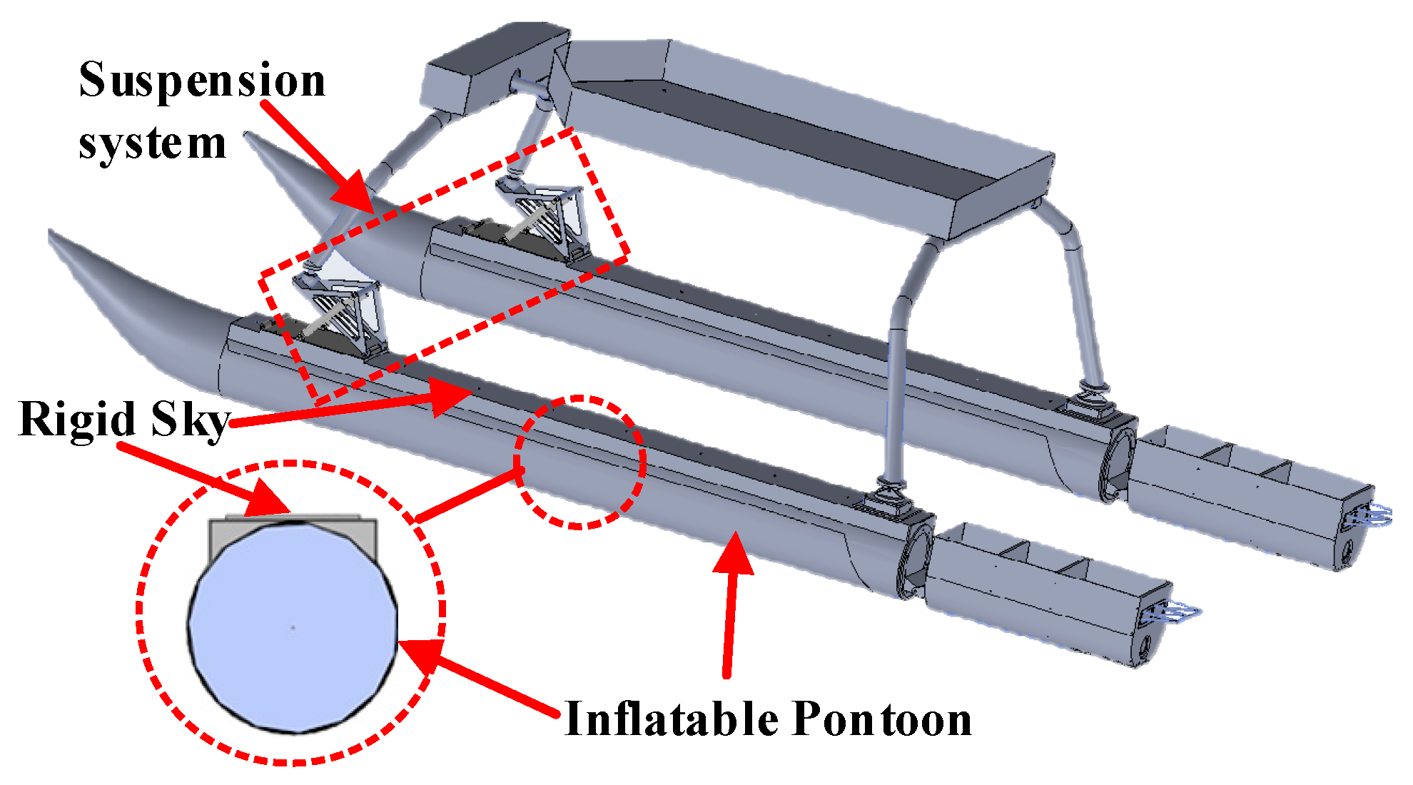
2.1. Structural Characteristics of the Rescue Vessel

The wave adaptive rescue vessel deviates from the conventional design principles of monohull and catamaran vessels by incorporating a new suspension system into its structural design. This innovation, illustrated in Figure 1, effectively minimizes the impact of wave excitation on the main cabin by providing a mechanism for buffering and absorbing irregular wave forces.
The vessel features two inflatable flexible pontoons made of PVC sandwich fabric, which resemble car tires [23]. These pontoons serve a dual purpose: firstly, they provide the necessary buoyancy for the entire vessel, akin to the supporting force exhibited by tires; secondly, they function as a vibration isolation and buffer mechanism. The compressed air within the pontoon exerts a non-linear restoring force, which effectively restrains the amplitude of wave excitation and prevents impact during the vibration isolation process. This is due to the favorable non-linear hard characteristics inherent to the flexible pontoon material. See Table 1.

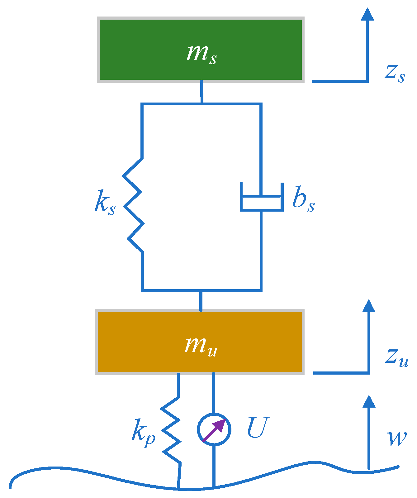
2.2. Dynamic Model of the Rescue Vessel

Given the intricate nature of the wave adaptive rescue vessel, a balance between precision and simplification in the model is essential when constructing the dynamic system model. In order to simplify the object of study and highlight the essence of the problem, different simplified models are usually used to describe it. Typically utilized simplified models include the whole-vessel seven-degrees-of-freedom model, the half-vessel four-degrees-of-freedom model and the quarter-vessel two-degrees-of-freedom model. The purpose of this study is to reduce the vibration of the rescue vessel in the vertical direction, so the rocking motion of the vessel in other directions is not considered for the time being and the ¼-vessel two-degrees-of-freedom model is used, as shown in Figure 2. Since the left and right pontoons and suspensions are symmetrical, this model disregards their reciprocal effects, resulting in a more accurate depiction of the vertical vibration reduction characteristics and greater computational efficiency [24]. Currently, the flexible pontoon has been substituted with a pliant solid object having a representational stiffness constant of kp.
Based on the two-degree-of-freedom vibration model shown in Figure 2, the Lagrange method is used to establish the following differential equation:
d d t ( T q ˙ j ) T q j = Q j j = 1 , 2 , , N
The specific vertical vibration model is obtained as follows:
{ m s z ¨ s = k s ( z s z u ) b s ( z ˙ s z ˙ u ) m u z ¨ u = k s ( z s z u ) + b s ( z ˙ s z ˙ u ) k p ( z u w ) + U
Take the state variables, and the output quantities as
x = [ z ˙ s , z ˙ u , z s , z u , w ] T ,   and   y = [ z ¨ s , z s z u , z u w ] T
In fact, it can be assumed that the main disturbance input to the system is the vertical displacement input of the wave, which can be simulated without a loss of generality by assuming randomly filtered white noise to simulate the vertical displacement of the wave [25].
w ˙ ( t ) = 2 π f 0 w ( t ) + 2 π G 0 v ω ( t )
Then, the system state equation is
{ x ˙ = A x + B u + G w y = C x
where the coefficient matrix is
A = [ b s m s b s m s k s m s k s m s 0 b s m u b s m u k s m u k s + k p m u k p m u 1 0 0 0 0 0 1 0 0 0 0 0 0 0 2 π f 0 ] B = [ 0 0 0 0 1 m u ] G = [ 0 0 0 0 2 π G 0 v ] C = [ b s m s b s m s k s m s k s m s 0 0 0 1 1 0 0 0 0 1 1 ]
Without considering the external active control force (i.e., U = 0), Figure 3 shows the influence of the radial stiffness of the pontoon on the RMS value of the main cabin acceleration, suspension dynamic travel, and pontoon relative displacement. The effect of pontoon stiffness on suspension dynamic travel is relatively small. As pontoon stiffness increases, the RMS value of pontoon relative displacement also increases, resulting in a worsening safety condition for the rescue vessel and an increased risk of “flying speed”. Pontoon stiffness significantly affects the RMS of the main cabin acceleration. Appropriately increasing the stiffness of the inflatable pontoon is conducive to improving ride comfort [26], and the vertical stiffness of the pontoon can be adjusted in real time in the system, thereby essentially changing the motion characteristics of the main cabin and achieving the goal of reducing the movement of the main cabin.

3. Vertical Dynamic Characteristics of Flexible Pontoons

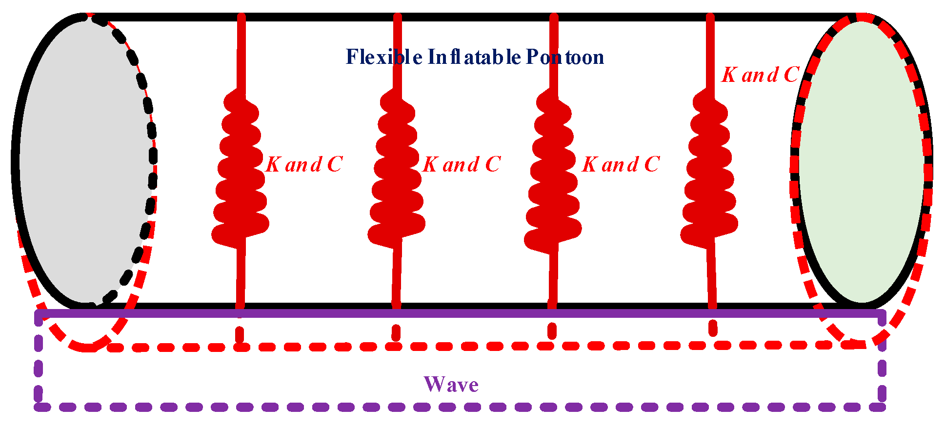
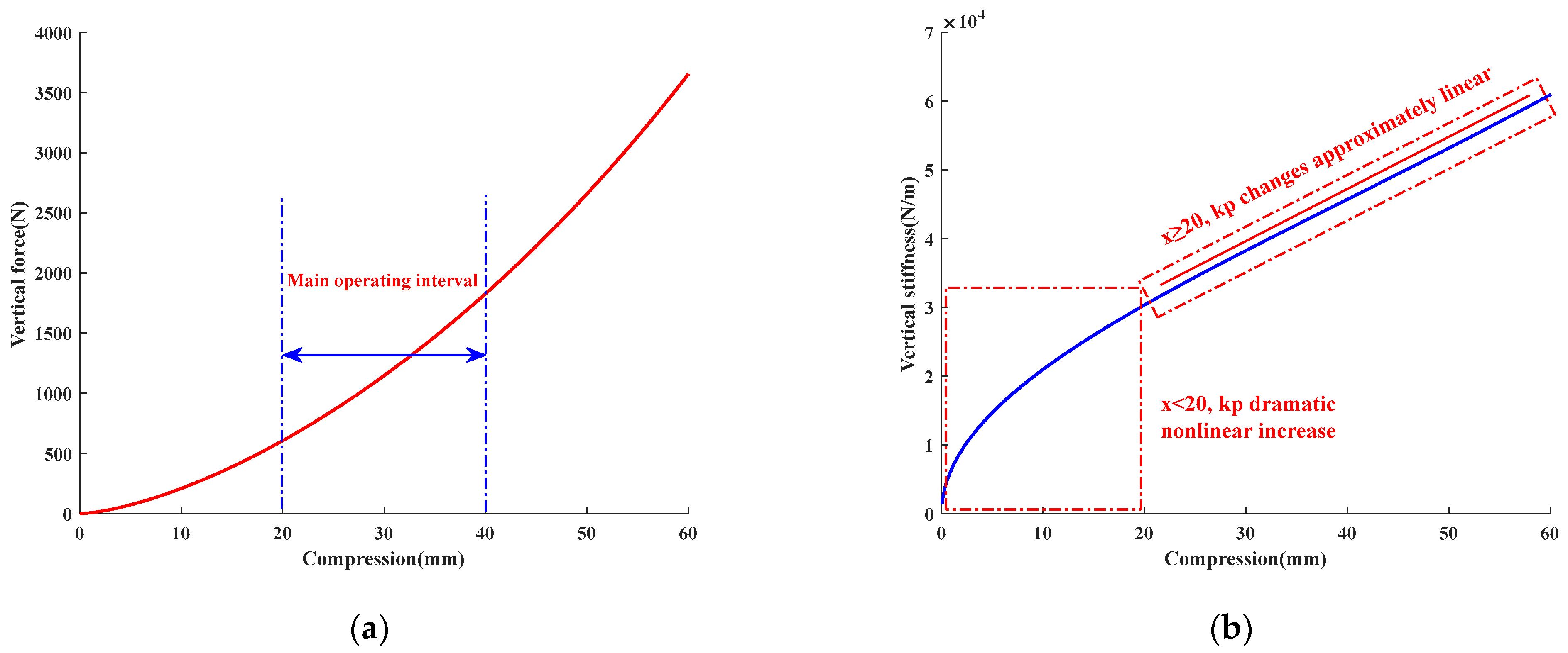
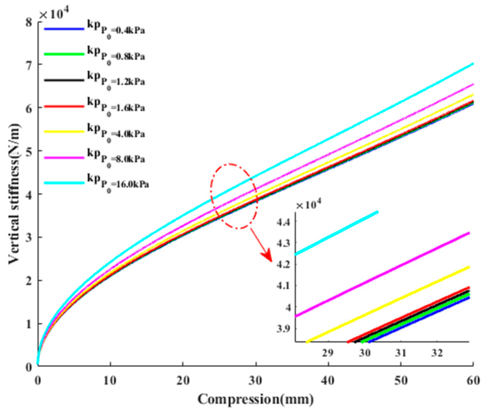
3.1. Mechanical Properties of Flexible Inflatable Pontoons

The study of mechanical properties pertaining to flexible inflatable pontoons is crucial in understanding the static stiffness of such pontoons. When subjected to wave load, a flexible inflatable pontoon undergoes deformation. The relationship between pontoon compression, changes in internal air pressure, and positive pressure relies on the coupling between pontoon material and the gas-filled inside. Denoting the initial volume and pressure as V0 and p0, respectively, when the pontoon is compressed, its internal volume decreases. Subsequently, the gas pressure within increases to p1, causing an increase in positive pressure on the rigid sky, as depicted in Figure 4.
According to Figure 5, the magnitude and direction of wave force are difficult to accurately calculate due to their random nature. Therefore, an approximate estimation is made, considering the force as vertically acting on the bottom surface of the pontoon. In order to study the static stiffness model of a flexible inflatable pontoon, the quasi-static compression process is employed as an equivalent alternative to the static compression process.

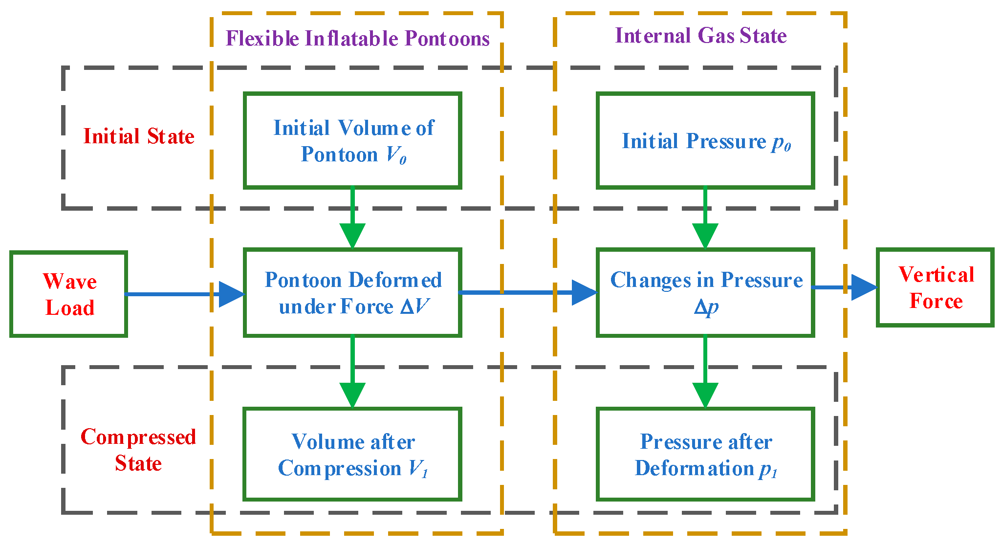
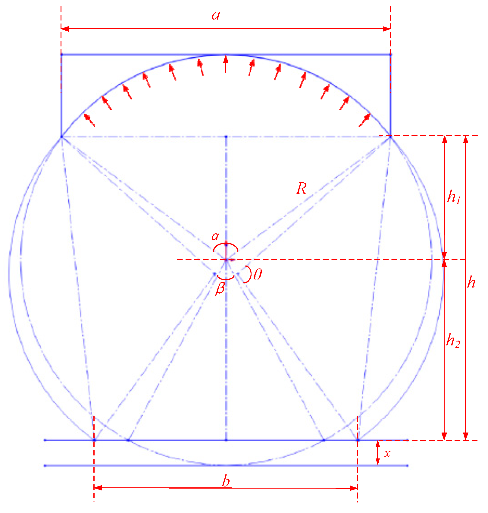
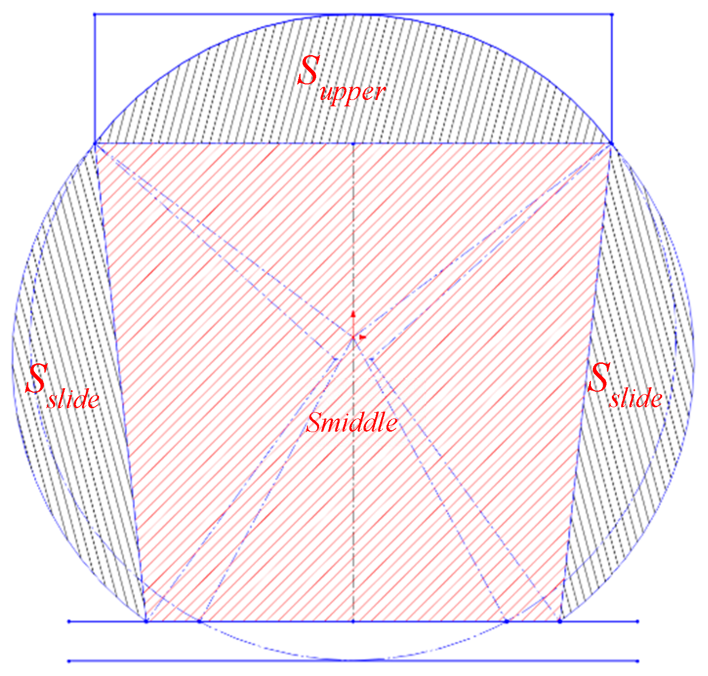
3.2. Dynamical Model of Flexible Inflatable Pontoons

In order to investigate the general geometric model of the flexible inflatable pontoon, several assumptions were made for the present study. These assumptions are as follows:
(1)
The flexible inflatable pontoon is composed of PVC sandwich fabric, which is considered to be an incompressible material within the pressure-bearing limit. This implies that both the circumference and length of the pontoon remain constant [27].
(2)
The force analysis only takes into account the cylindrical section of the flexible inflatable pontoon, while neglecting the effects of the conical section.
(3)
The initial cross-section of the inflatable pontoon is assumed to be a regular circle. However, after compression deformation occurs in the non-contact section, the cross-section shape is replaced by a regular arc with an unchanged radius [28].
(4)
The gas state variation within the flexible inflatable pontoon is considered to be an isothermal process.
A single flexible inflatable pontoon is taken as the object of study. The original shape of the flexible inflatable pontoon is a cylinder and the cross-section of the pontoon is shown in Figure 6. Under the action of the waves, the vertical deformation occurs. According to the assumptions, it is only necessary to find the change in the cross-section of the flexible pontoon before and after the deformation, so that the vertical mechanical properties of the flexible pontoon can be derived.
From the assumption of a constant perimeter after deformation, it follows that
θ = ( 2 π α β ) / 2
The distance h from the end-chord length a of the rigid sky to the wave-action surface b can be divided into
h = R 2 ( a / 2 ) 2 + R x
The length b of the line of intersection between the cross-section of the pontoon and the wave action surface, and the corresponding circular angle of that section of the arc β can be expressed as a function of x.
b = 2 R · arccos ( ( R x ) / R )
β = 2 arccos ( h 2 / R ) = 2 arccos ( ( R x ) / R )
After wave load, the cross-section S of the pontoon consists of three circular surfaces (Supper and Sslide) and a trapezoidal surface Smiddle, as shown in Figure 7. Based on the above analysis, the cross-sectional area S of the deformed pontoon can be obtained.
S = S u p p e r + 2 S s l i d e + S m i d d l e
The flexible inflatable pontoon can be approximated as a column after deformation; its length L does not change, the pontoon is a confined space, and it satisfies the ideal gas equation of state:
p V m = C
m is the polytropic index, which is used to describe the quasi-static process of the ideal gas and is related to the gas flow speed. As the pontoon is always in contact with seawater, the gas change process in the pontoon is approximated as an isothermal process, i.e., m is taken as 1 [29], so that for an arbitrary wave load it is obtained that
( p 0 + p a ) V 0 = ( p 1 + p a ) V 1
The rigid sky and the upper part of the pontoon are closely fitted. According to the calculation method of hydrostatic pressure force, the resultant force acting on the arc surface of the rigid sky is equal to the vertical force acting on the plane S0 where the chord line is located under the same pressure, and so it is obtained that
F = p 1 S 0
Thus, the static stiffness k of the flexible inflatable pontoon can be obtained as follows:
k = d F d x = S 0 d p 1 d x = S 0 ( p 1 + p a ) V 0 V 1 2 d V d x
From Equation (13), it can be seen that the vertical force and static stiffness of the flexible inflatable pontoon are mainly influenced by the internal gas pressure, which is related to the initial pressure of the internal gas and the geometric parameters of the pontoon [30].
The derivation process that was discussed above is performed under ideal conditions. It takes into account the scenario where the flexible inflatable pontoon does not undergo any deformations, denoted as x = 0 m. During this time, if p0 ≠ 0 pa, there exists an initial pressure inside the flexible pontoon, which acts on its inner wall. In addition, assumption (1) assumes that within the pressure-bearing limit, the PVC sandwich fabric can be considered as an incompressible material; hence, no deformation of the pontoon occurs. Consequently, the initial pressure p0 that acts vertically in plane S0, where the chord at the bottom of the rigid sky is located, should be zero. To ensure this, a correction must be applied to the vertical force of the flexible pontoon by subtracting the vertical force p0 acting in plane S0. It is worth mentioning that this correction does not compromise the accuracy of the static stiffness.
To solve for the vertical force and static stiffness of the flexible inflatable pontoon, we utilized the actual dimensions of the wave adaptive rescue vessel. The results obtained are presented in Figure 8. Upon examining the calculations, it becomes apparent that the vertical force F of the pontoon varies non-linearly with the compression x under wave load and experiences an approximately linear relationship during its primary operational range. Furthermore, the static stiffness of the flexible inflatable pontoon demonstrates a sharp increase when the deformation is less than 20 mm. Afterwards, it follows an approximately linear pattern once the deformation surpasses or equals 20 mm [31]. Subsequently, the static stiffness continues to increase as the compression increases.

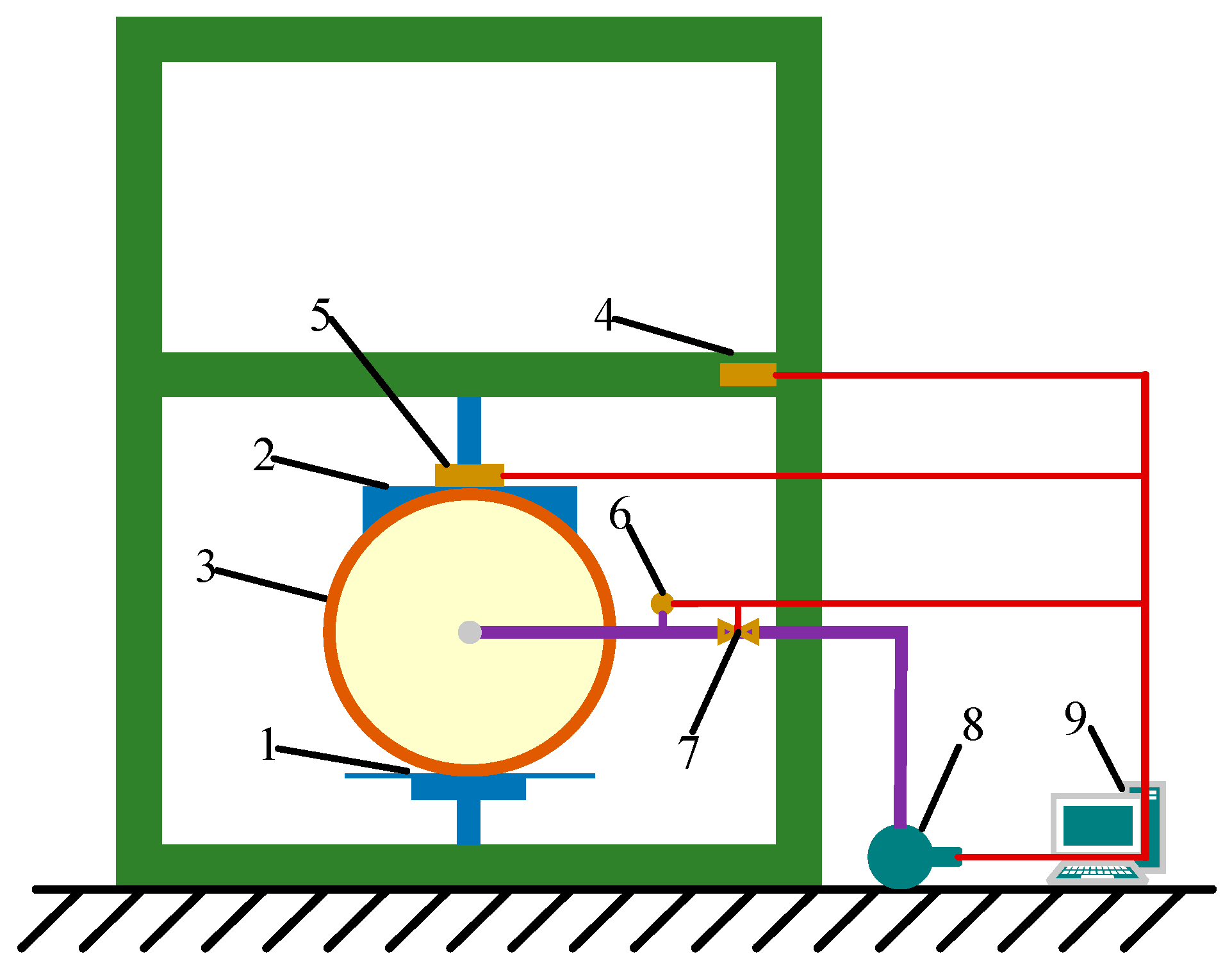
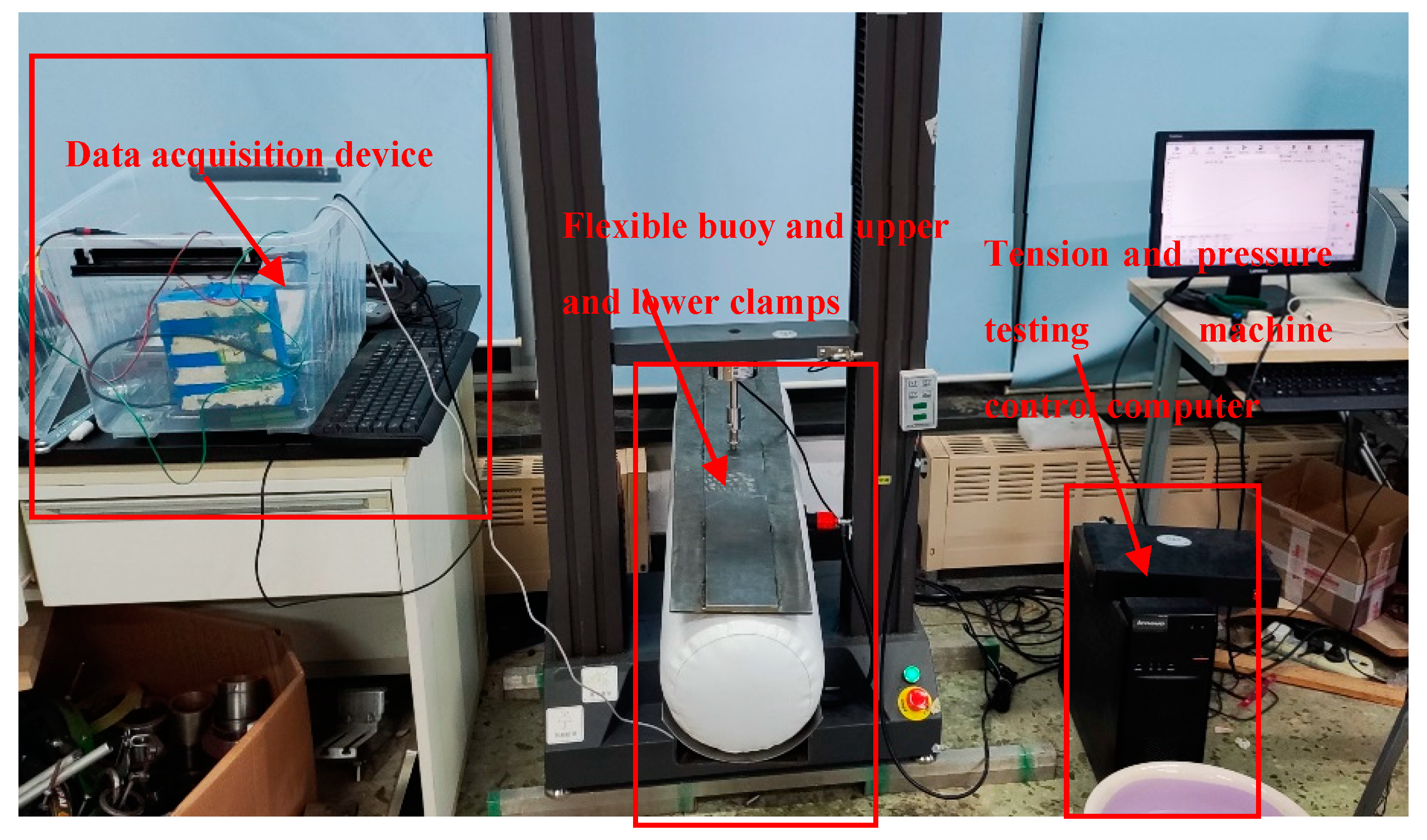
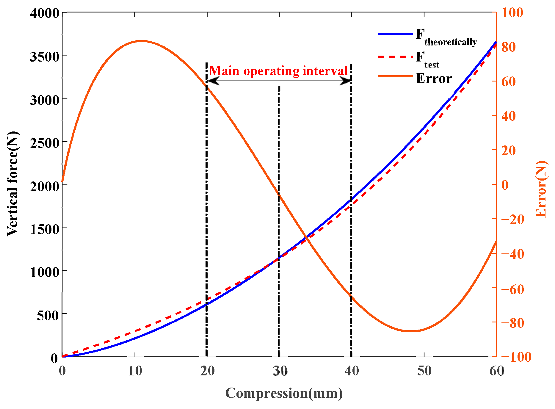
3.3. Experimental Verification of the Dynamic Properties of Flexible Pontoons

To verify the accuracy of the solution for the vertical dynamic characteristics of the flexible pontoon, we designed an identical upper and lower champ to simulate the real vessel installation. For the testing equipment, we selected the Shanghai Xieqiang ctm8010 test system. This system utilizes servo motors to drive the beam in an upward and downward motion, thereby facilitating the test loading process. Figure 9 presents the schematic diagram of the test equipment.
The experimental test device and data acquisition device are shown in Figure 10. The displacement and vertical force between the upper and lower clamps are collected in real-time by the data acquisition device, which also automatically releases the pressure upon reaching the maximum stroke. To determine the vertical static stiffness, the collected force–displacement data can be differentiated with respect to displacement [32]. According to Figure 11, a comparison is made between the theoretical solution and the experimental results of force–displacement. It can be observed that the trend and magnitude of the theoretical and experimental outcomes exhibit a strong agreement, with a maximum absolute error of 84.278 N and a maximum relative error of 10.5%.
By analyzing the mechanical characteristics of the flexible inflatable pontoon and its geometrical model, a calculation method for obtaining the vertical dynamic characteristics of the pontoon is obtained. The results from the solution show good agreement with the test results. The vertical static stiffness of the pontoon exhibits excellent nonlinear characteristics. In addition, the radius R, the width of the rigid sky a, the central angle α corresponding to the rigid sky, and the initial internal air pressure p0 can adjust the vertical stiffness of the pontoon to avoid the resonance region of the system and limit the vertical motion amplitude of the main cabin [33]. Even after determining the geometric size of the flexible inflatable pontoon, the stiffness magnitude can still be artificially varied by adjusting the internal air pressure p0, as shown in Figure 12, thereby actively adjusting the wind and wave resistance of the entire vessel to improve the range of sea conditions to which the vessel can adapt [34].

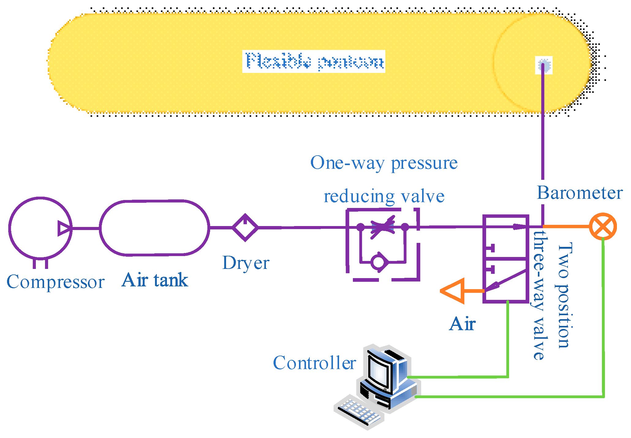
4. Semi-Active Control System Based on the Dynamic Characteristics of Flexible Pontoons

4.1. Design of the Semi-Active Control System

In the passive suspension system model, the flexible pontoon is treated as a spring with a fixed stiffness, without considering its dynamic characteristic, which allows for the artificial alteration of the vertical force by changing the internal air pressure of the flexible pontoon. This property of the flexible pontoon is utilized in the design of a semi-active control system, as shown in Figure 13. The control system consists of several components including a small compressor, storage tank, dryer, single check valve, electromagnetic two-position three-way valve, manometer, controller, and corresponding pipelines. The controller regulates the electromagnetic two-position three-way valve to adjust the air pressure within the flexible pontoon, thus actively generating the desired vertical force. This improvement effectively enhances the vertical motion characteristics of the main hull.

4.2. LQR Controller Design

The suspension performance indicators for evaluating wave adaptative rescue vessels include main cabin vertical acceleration, which represents ride comfort; suspension dynamic travel, which affects the attitude of the main cabin and is related to structural design and arrangement; and pontoon dynamic displacement, which represents maneuvering stability [35]. Consequently, the LQR controller is designed with consideration for these performance indicators.
J = 0 [ e 1 ( z s z u ) 2 + e 2 ( z u w ) 2 + e 3 z ¨ 2 s ] d t
Substituting the state space equations of the semi-active control suspension model into Equation (14), the quadratic objective function can be obtained as follows:
J = 0 [ x T Q x + u T R u + 2 x T N u ] d t
where Q = C T E C , E = d i a g ( e 3 , e 1 , e 2 ) , R = 0.01 , N = 0 .
According to optimal control theory, the control law is considered to be linear and the control force can be expressed as
U = K x
K can satisfy the minimum system performance index for a given condition when
K = R 1 B T P
The matrix P is given by the Algebraic Riccati Equation (ARE) as
P A + A T P P B R 1 B T P + Q = 0
Q is the semi-definite state weighting matrix and R is the positive definite control weighting matrix. The optimal control core of a semi-active suspension based on the vertical dynamic characteristics of a flexible pontoon lies in the selection of Q and R. Q is related to the weighting coefficients e1, e2, e3 related to the performance indicators. In previous designs, the weighted coefficients are often obtained by the designers through repeated trial and error according to their experience [36]. Although the corresponding optimal control law can be obtained, such an optimum is highly subjective [37]. How to choose the weight coefficient reasonably also becomes crucial, and then genetic algorithm is used to optimize the weight coefficient in the design of the LQR controller [38].

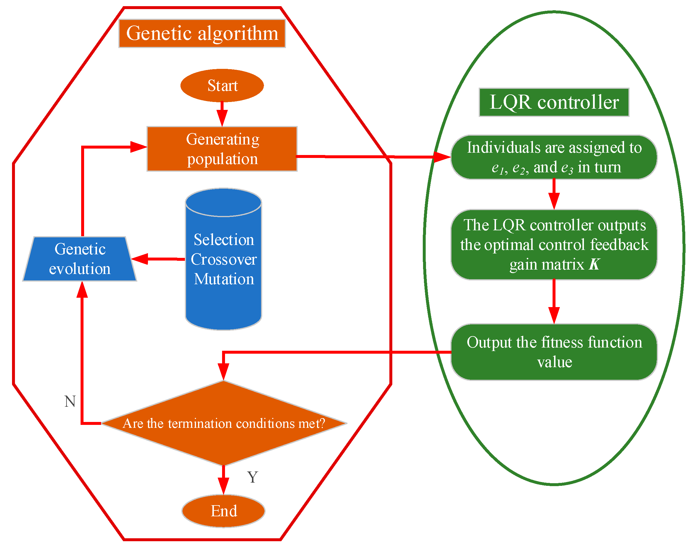
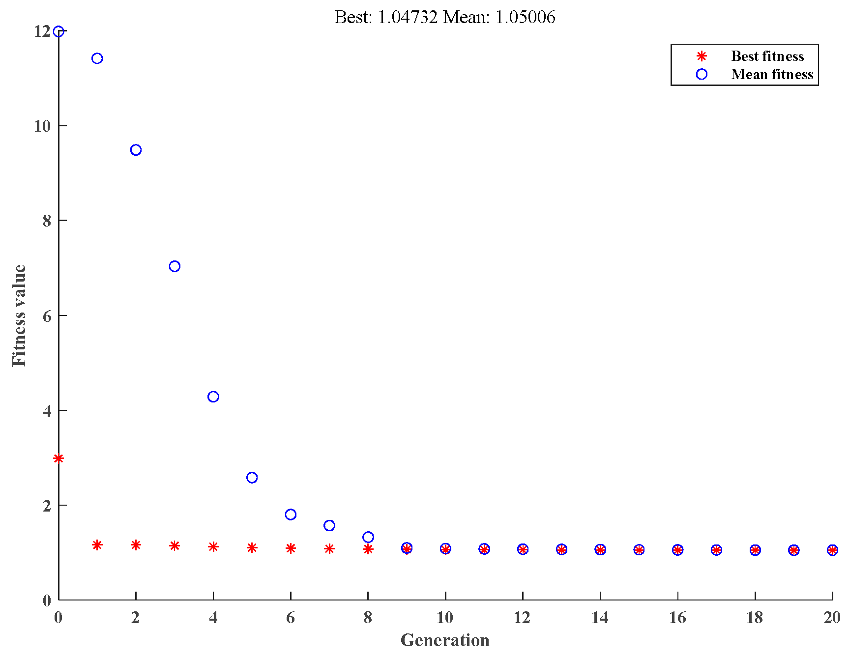
4.3. LQR Weighting Coefficient Optimization Based on Genetic Algorithm

The genetic algorithm is a stochastic, parallel, and adaptive global optimization method that simulates the natural selection and evolutionary mechanisms observed in the biological world. The optimization variables in our study are indicator weighting coefficients X = [e1, e2, e3]. To establish the fitness function of the genetic algorithm, we consider the performance constraint indicators, namely, z ¨ 2 , ( z s z u ) 2 , ( z u w ) 2 . Due to the inconsistent units and orders of magnitude of these indicators, we derive the fitness function by normalizing them based on the corresponding values obtained from the passive suspension system. The formulation of the optimization problem is as follows:
min O = R M S ( z s ) R M S ( z s ) p + R M S ( z s z u ) R M S ( z s z u ) p + R M S ( z s w ) R M S ( z s w ) p
X = ( e 1 , e 2 , e 3 ) , 0.01 < X i < 10 6 , i = 1 , 2 , 3
s . t . { R M S ( z s ) < R M S ( z s ) p R M S ( z s z u ) < R M S ( z s z u ) p R M S ( z s w ) < R M S ( z s w ) p
For each group of weighted coefficients X, fitness function O is calculated to determine whether constraint conditions (20) and (21) are met. If both conditions are satisfied, the value of the fitness function is the obtained O; otherwise, the fitness function value calculated by the weighting coefficient of the group is punished to make it far away from the minimum value, thus guiding the evolution of the population in the direction of meeting the constraints [39]. The optimization process for determining the weighting coefficients of the LQR controller using the genetic algorithm is depicted in Figure 14.
The generation of initial populations, selection, crossover, and mutation functions, as well as the configuration of key parameters, all have an impact on the optimization results of a genetic algorithm. The relevant configurations are presented in Table 2.

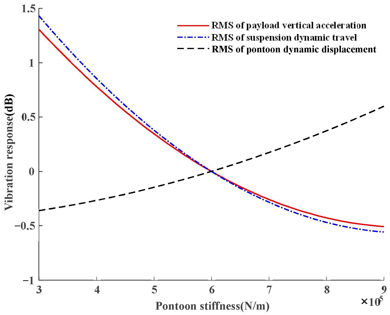
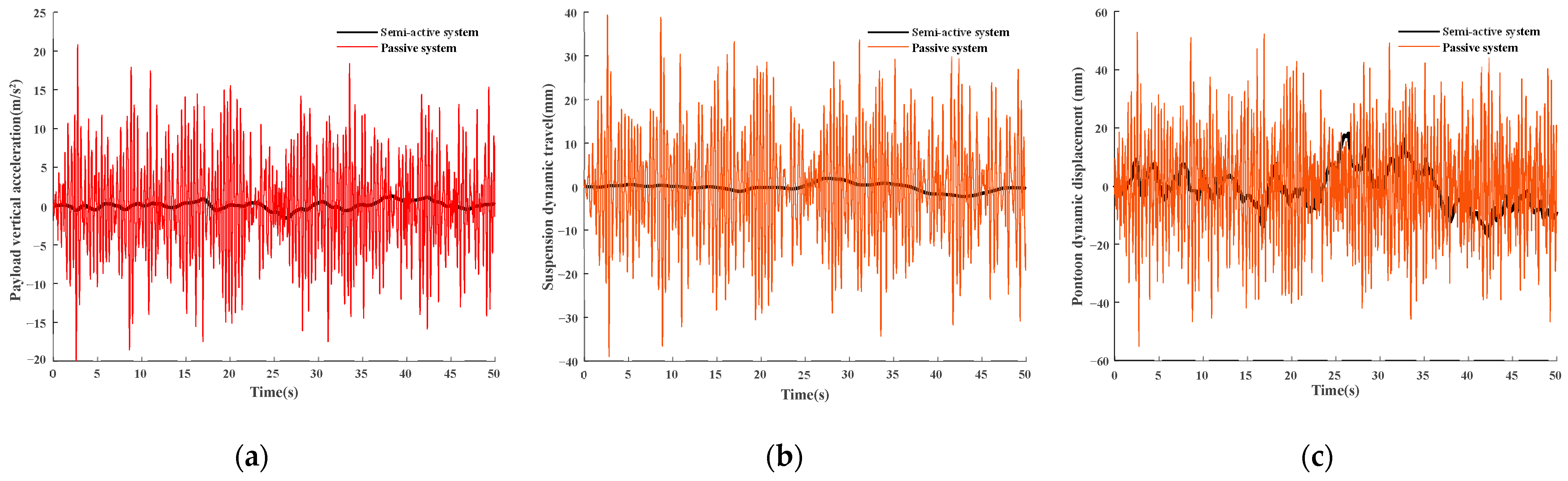
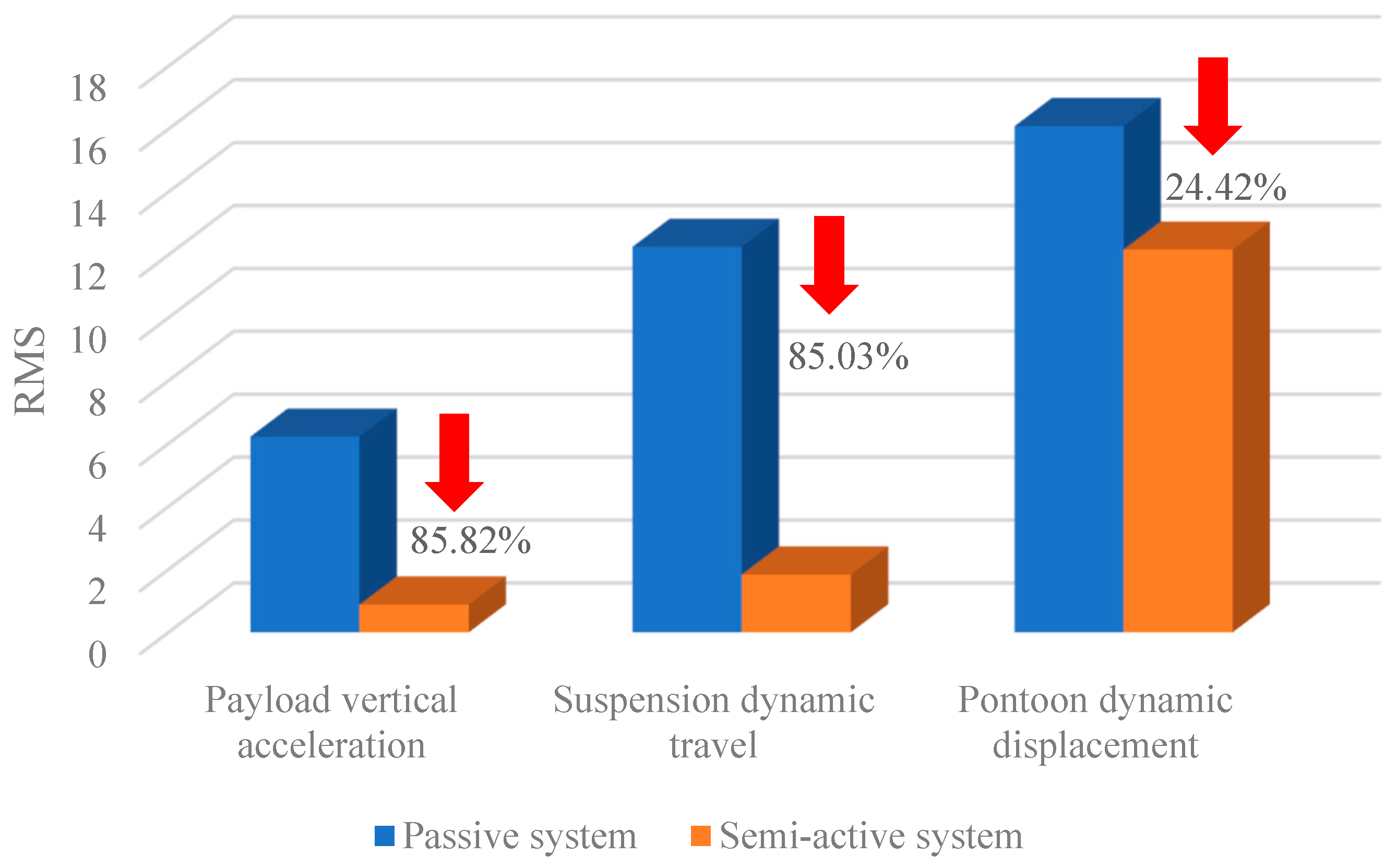
5. Simulation Results and Discussion

It can be seen that as the population continues to evolve, the best individual fitness function value constantly decreases, and, finally, in the 20th generation convergence to 1.04732 occurs, at which point the corresponding optimal individual is (e1, e2, e3) = (951,632.4648260964, 6.581172322675923, 15.251), as shown in Figure 15. The entire computation process takes approximately 15 min.
According to the value of E, the corresponding most feedback matrix K is solved, and the corresponding performance index can be obtained by bringing it into the semi-active control system. The main cabin acceleration, suspension dynamic travel, and pontoon dynamic displacement are shown in Figure 16, from which it can be seen that the semi-active system can effectively reduce the main cabin acceleration, suspension dynamic travel, and pontoon dynamic displacement values to achieve the purpose of weakening the vessel’s motion under wave excitation.
Figure 17 presents a comparison of multiple optimization indicators between the semi-active control system and the passive suspension. It is evident that the implementation of the LQR controller, designed using a genetic algorithm, greatly enhances the performance of the semi-active suspension system in comparison to the passive suspension.

6. Conclusions

In this paper, a theoretical and experimental investigation on the vertical dynamic characteristics of the flexible pontoon of a suspended high-speed rescue vessel was carried out. A semi-active control system was designed based on the vertical dynamic characteristics of the flexible pontoon. The weight coefficients of the LQR controller were optimized using genetic algorithms, and some conclusions were obtained as follows.
A two-degrees-of-freedom model of the suspended high-speed rescue vessel was analyzed, and it was found that by adjusting the stiffness of the pontoons, it was possible to essentially change the motion characteristics of the vessel under wave excitation.
The maximum relative error between the theoretical calculation and experimental values of the vertical force of the flexible pontoon is 10.5%. Under wave load, the vertical force of the pontoon varies non-linearly with the amount of compression, and approximately linearly in its main working interval. The static stiffness of the flexible inflatable pontoon increases sharply in the range of less than 20 mm in deformation and varies approximately linearly after the deformation is greater than or equal to 20 mm, increasing with compression. By varying the internal air pressure p0, the pontoon stiffness can be artificially changed, thus actively regulating the wind and wave resistance of the whole vessel, and improving the range of sea conditions to which the vessel can adapt.
The optimization of LQR weighting coefficients based on genetic algorithm avoids the problem of artificially setting weighting coefficients in traditional control systems, and achieves the purpose of finding the optimal feedback matrix in a certain range and constraint. Simulation results demonstrate that the LQR controller, designed using the genetic algorithm, significantly outperforms the passive suspension system. The RMS value of main cabin acceleration is reduced by 85.82%, while the RMS value of suspension dynamic travel experiences an 85.03% reduction and the RMS value of pontoon dynamic displacement is lowered by 24.42%. These outcomes convincingly indicate the effective attenuation of the vessel’s vertical motion.
Due to the hysteresis of air pressure control, the actual effect of the semi-active control system may be affected to some extent. However, research on the active adjustment of the vessel’s motion characteristics by artificially and dynamically regulating the internal air pressure of the flexible pontoon will continue. Future work involves constructing a test platform to conduct experimental investigations based on this concept.

Author Contributions

Conceptualization, J.L., Z.L. (Zheng Li), Y.W., X.X., Z.L. (Zhi Li) and W.X.; methodology, J.L. and W.X.; software, J.L. and W.X.; validation, J.L., Z.L. (Zheng Li), Y.W., X.X., Z.L. (Zhi Li) and W.X.; formal analysis, J.L. and W.X.; investigation, J.L. and W.X.; resources, J.L. and W.X.; data curation, J.L.; writing—original draft preparation, J.L. and W.X.; writing—review and editing, J.L. and W.X.; visualization, J.L. and W.X.; supervision, W.X.; project administration, J.L. and W.X.; funding acquisition, W.X. All authors have read and agreed to the published version of the manuscript.

Funding

This research was funded by the National Natural Science Foundation of China, grant numbers 51905066 and 52075065.

Institutional Review Board Statement

Not applicable.

Informed Consent Statement

Not applicable.

Data Availability Statement

The data presented in this study are available upon request from the corresponding authors.

Acknowledgments

The authors acknowledge technical support from the Dalian Maritime University School of Marine Engineering staff. The authors appreciate the feedback of the reviewers and the editors on this submission.

Conflicts of Interest

The authors declare no conflict of interest.

Nomenclature

RFlexible pontoon radius
Greeks LFlexible pontoon length
ω(t)Gaussian white noiseaThe chord length of the pontoon corresponding to the rigid sky
αCentral angle of abThe chord length of the pontoon corresponding to the wave
βCentral angle of bxCompression of the pontoon
θThe center angle corresponding to the arc of the non-contact sectionS0The plane area of the rigid-sky-bottom chord length
hDistance from the end of the rigid sky to the surface of the wave
Variables pInternal pressure
paStandard atmosphere
wWave vertical excitation displacementVFlexible pontoon volume
zuDisplacement of the flexible pontoon in the vertical directionCConstant
zsDisplacement of the payload in the vertical directionmGas polytropic index
qjThe jth generalized coordinatee1The weight coefficient of suspension dynamic travel
QjGeneralized force for the jth generalized coordinatee2The weight coefficient of pontoon dynamic displacement
TSystem kinetic energye3The weight coefficient of payload vertical acceleration
NNumber of complete constraint equationsQSemi-definite state weighting matrix
vSpeed of the high-speed vesselRPositive definite control weighting matrix
f0Lower cut-off frequency of ocean wavesNCorrelation weighting matrix
G0Simulated wave stateKOptimal feedback matrix
UActive control force of flexible pontoonPAuxiliary matrix

References

  1. Lawther, A.; Griffin, M.J. A survey of the occurrence of motion sickness amongst passengers at sea. Aviat. Space Environ. Med. 1988, 59, 399–406. [Google Scholar] [PubMed]
  2. Lawther, A.; Griffin, M.J. The motion of a ship at sea and the consequent motion sickness amongst passengers. Ergonomics 1986, 29, 535–552. [Google Scholar] [CrossRef] [PubMed]
  3. Fang, C.; Chan, H. An investigation on the vertical motion sickness characteristics of a high-speed catamaran ferry. Ocean Eng. 2007, 34, 1909–1917. [Google Scholar] [CrossRef]
  4. Stevens, S.C.; Parsons, M.G. Effects of Motion at Sea on Crew Performance: A Survey. Mar. Technol. 2002, 39, 29–47. [Google Scholar] [CrossRef]
  5. Lovalekar, M.; Perlsweig, K.A.; Keenan, K.A.; Baldwin, T.M.; Caviston, M.; McCarthy, A.E.; Parr, J.J.; Nindl, B.C.; Beals, K. Epidemiology of musculoskeletal injuries sustained by Naval Special Forces Operators and students. J. Sci. Med. Sport 2017, 20 (Suppl. 4), S51–S56. [Google Scholar] [CrossRef]
  6. Peterson, S.N.; Call, M.H.; Wood, D.E.; Unger, D.V.; Sekiya, J.K. Injuries in Naval Special Warfare Sea, Air, and Land Personnel: Epidemiology and Surgical Management. Oper. Techn. Sport Med. 2005, 13, 131–135. [Google Scholar] [CrossRef]
  7. Townsend, N.C.; Coe, T.E.; Wilson, P.A.; Shenoi, R.A. High-speed marine craft motion mitigation using flexible hull design. Ocean Eng. 2012, 42, 126–134. [Google Scholar] [CrossRef]
  8. McMorris, T.; Myers, S.; Dobbins, T.; Hall, B.; Dyson, R. Seating type and cognitive performance after 3 h travel by high-speed boat in sea states 2–3. Aviat. Space Environ. Med. 2009, 80, 24–28. [Google Scholar] [CrossRef]
  9. Halswell, P.K.; Wilson, P.A.; Taunton, D.J.; Austen, S. An experimental investigation into whole body vibration generated during the hydroelastic slamming of a high speed craft. Ocean Eng. 2016, 126, 115–128. [Google Scholar] [CrossRef]
  10. Pandey, J.; Hasegawa, K. Study on Turning Manoeuvre of Catamaran Surface Vessel with a Combined Experimental and Simulation Method. IFAC-PapersOnLine 2016, 49, 446–451. [Google Scholar] [CrossRef]
  11. Coe, T.E.; Xing, J.T.; Shenoi, R.A.; Taunton, D. A simplified 3-D human body–seat interaction model and its applications to the vibration isolation design of high-speed marine craft. Ocean Eng. 2009, 36, 732–746. [Google Scholar] [CrossRef]
  12. Li, J.; Bai, X.; Li, Y.; Du, H.; Fan, F.; Li, S.; Li, Z.; Xiong, W. Investigation of a Cabin Suspended and Articulated Rescue Vessel in Terms of Motion Reduction. J. Mar. Sci. Eng. 2022, 10, 1966. [Google Scholar] [CrossRef]
  13. Fratello, J.; Ahmadian, M. Multi-body dynamic simulation and analysis of wave-adaptive modular vessels. In Proceedings of the 11th International Conference on Fast Sea Transportation FAST 2011, Honolulu, HI, USA, 1 January 2011; pp. 777–783. [Google Scholar]
  14. Dhanak, M.R.; Ananthakrishnan, P.; Frankenfield, J.; von Ellenrieder, K. Seakeeping characteristics of a wave-adaptive modular unmanned surface vehicle. In Proceedings of the International Conference on Offshore Mechanics and Arctic Engineering—OMAE, Nantes, France, 9–14 June 2013. [Google Scholar] [CrossRef]
  15. Mousaviraad, M.; Conger, M.; Stern, F.; Peterson, A.; Ahmadian, M. Validation of CFD-MBD FSI for high-fidelity simulations of full-scale WAM-V Sea-Trials with suspended payload. In Proceedings of the 13th International Conference on Fast Sea Transportation, FAST 2015, Washington, DC, USA, 2–4 September 2015. [Google Scholar] [CrossRef]
  16. Ferrandis, D.Á.; Brizzolara, S.; Chryssostomidis, C. Influence of large hull deformations on the motion response of a fast catamaran craft with varying stiffness. Ocean Eng. 2018, 163, 207–222. [Google Scholar] [CrossRef]
  17. Han, J.; Maeda, T.; Kinoshita, T.; Kitazawa, D. Towing Test and Motion Analysis of a Motion-Controlled Ship-Based on an Application of Skyhook Theory. In Proceedings of the 12th International Conference on the Stability of Ships and Ocean Vehicles, Glasgow, UK, 14–19 June 2015. [Google Scholar]
  18. Kanno, S.; Han, J.; Maeda, T.; Yoshida, T.; Kitazawa, D. Numerical Simulation of Motion controlled Fishery Boat with Harvesting Wave Energy. In Proceedings of the ASME 2017 36th International Conference on Ocean, Offshore and Arctic Engineering, OMAE 2017, Trondheim, Norway, 25–30 June 2017. [Google Scholar] [CrossRef]
  19. Han, J.; Kitazawa, D.; Kinoshita, T.; Maeda, T.; Itakura, H. Experimental investigation on a cabin-suspended catamaran in terms of motion reduction and wave energy harvesting by means of a semi-active motion control system. Appl. Ocean Res. 2019, 83, 88–102. [Google Scholar] [CrossRef]
  20. Alex, R.J.; Richard, M. A Revolutionary Ride Control System for Multi-Hull High Speed Marine Vessels. In Proceedings of the Proceedings of the International Conference High Speed Marine Vessels, Fremantle, Australia, 2–3 March 2011. [Google Scholar]
  21. Yachts, S. Velodyne Marine. 2023. Available online: https://www.yachtsinternational.com/owners-lounge/velodyne-marine (accessed on 12 August 2023).
  22. Li, J.; Xiong, W.; Wang, H. The Research on Modeling and Simulation of Wave Adaptive Vessel. In Proceedings of the 8th IEEE International Conference on Fluid Power and Mechatronics, FPM 2019, Wuhan, China, 10–13 April 2019; pp. 1055–1059. [Google Scholar] [CrossRef]
  23. Zhang, B.; Xu, T.; Wang, H.; Huang, Y.; Chen, G. Vertical Tire Forces Estimation of Multi-Axle Trucks Based on an Adaptive Treble Extend Kalman Filter. Chin. J. Mech. Eng. 2021, 34, 55. [Google Scholar] [CrossRef]
  24. Theunissen, J.; Tota, A.; Gruber, P.; Dhaens, M.; Sorniotti, A. Preview-based techniques for vehicle suspension control: A state-of-the-art review. Annu. Rev. Control 2021, 51, 206–235. [Google Scholar] [CrossRef]
  25. Balan, R.M. Stochastic wave equation with Lévy white noise. arXiv 2021, arXiv:2111.14242. [Google Scholar] [CrossRef]
  26. Nigwal, D.; Pasi, D.K.; Chouksey, M. Effect of nonlinear conical springs on the vibration characteristics of seven degree-of-freedom car model using MATLAB/Simscape. Int. J. Dynam. Control 2023, 11, 491–503. [Google Scholar] [CrossRef]
  27. Yu, L.; Li, Y.; Xia, L.; Ding, J.; Yang, Q. Research on mechanics of ship-launching airbags I-Material constitutive relations by numerical and experimental approaches. Appl. Ocean Res. 2015, 52, 222–233. [Google Scholar] [CrossRef]
  28. Gao, D.; Lu, F. Study on shock response of cushion packaging system based on combined model using hyperbolic tangent and tangent functions with consideration of rotation effect. Appl. Mech. Mater. 2011, 102, 1161–1166. [Google Scholar] [CrossRef]
  29. Holtz, M.W.; Niekerk, J.L.V. Modelling and design of a novel air-spring for a suspension seat. J. Sound Vib. 2010, 329, 4354–4366. [Google Scholar] [CrossRef]
  30. Zhou, R.; Zhang, B.; Li, Z. Dynamic modeling and computer simulation analysis of the air spring suspension. J. Mech. Sci. Technol. 2022, 36, 1719–1727. [Google Scholar] [CrossRef]
  31. An, J.; Chen, G.; Deng, X.; Xi, C.; Wang, T.; He, H. Analytical study of a pneumatic quasi-zero-stiffness isolator with mistuned mass. Nonlinear Dyn. 2022, 108, 3297–3312. [Google Scholar] [CrossRef]
  32. Guomin, X.; Wei ZH, O.U.; Lin, H. Vertical dynamic characteristics of cuboid type air springs. J. Vib. Shock 2018, 37, 248–253. Available online: http://jvs.sjtu.edu.cn/EN/Y2018/V37/I7/247 (accessed on 13 August 2023).
  33. Zhang, X.; Cao, Q.; Qiu, H.; Liang, T.; Huang, W. Dynamic Analysis of a Loading-Adapting Quasi-Zero-Stiffness Isolation System Based on the Rolling Lobe Air-Springs. J. Vib. Eng. Technol. 2022, 10, 3207–3225. [Google Scholar] [CrossRef]
  34. Wei, Y.; Wu, M.; Tang, Z.; Yang, L.; Lv, J. Nonlinear Transfer Characteristics of Air Spring Struts with High-Fidelity Quarter-Car Tests and Theoretical Modeling. J. Vib. Eng. Technol. 2023, 11, 2453–2465. [Google Scholar] [CrossRef]
  35. Lai, F.; Deng, Z. Integrated control of automotive four wheel steering and active suspenion systems based on unifrom model. In Proceedings of the ICEMI 2009—Proceedings of 9th International Conference on Electronic Measurement and Instruments, Beijing, China, 16–19 August 2009; pp. 3551–3556. [Google Scholar] [CrossRef]
  36. Miyamoto, K.; She, J.; Sato, D.; Yasuo, N. Automatic determination of LQR weighting matrices for active structural control. Eng Struct. 2018, 174, 308–321. [Google Scholar] [CrossRef]
  37. Hu, J.; Liu, R.; Xie, Z.; Zhang, D.; Zhu, G. Research on an Active Vibration Isolation System with Hybrid Control Strategy for The Guidance System of TBM. J. Vib. Eng. Technol. 2023. [Google Scholar] [CrossRef]
  38. Habib, M.; Khoucha, F.; Harrag, A. GA-based robust LQR controller for interleaved boost DC-DC converter improving fuel cell voltage regulation. Electr. Power Syst. Res. 2017, 152, 438–456. [Google Scholar] [CrossRef]
  39. Ghoreishi, S.A.; Nekoui, M.A. Optimal Weighting Matrices Design for LQR Controller Based on Genetic Algorithm and PSO. AMR 2012, 433–440, 7546–7553. [Google Scholar] [CrossRef]
Figure 1. Diagram of the rescue vessel pontoon mechanism.
Jmse 11 01747 g001
Figure 2. Two-degree-of-freedom model of the rescue vessel.
Jmse 11 01747 g002
Figure 3. Curve of pontoon stiffness on key parameters.
Jmse 11 01747 g003
Figure 4. Mechanical properties of flexible inflatable pontoons.
Jmse 11 01747 g004
Figure 5. Simplified force model diagram of the pontoon.
Jmse 11 01747 g005
Figure 6. Cross-section of flexible inflatable pontoon.
Jmse 11 01747 g006
Figure 7. Cross-section changes after deformation.
Jmse 11 01747 g007
Figure 8. (a) Vertical force with compression; (b) static stiffness with compression.
Jmse 11 01747 g008
Figure 9. Schematic diagram of the test set-up: 1. lower clamping piece; 2. upper clamping piece; 3. pontoon; 4. displacement sensor; 5. pressure sensor; 6. pressure gauge; 7. air valve; 8. air compressor; 9. computer.
Jmse 11 01747 g009
Figure 10. Compression test arrangement.
Jmse 11 01747 g010
Figure 11. Comparison of solution results with experimental results.
Jmse 11 01747 g011
Figure 12. The curve of vertical stiffness with internal pressure.
Jmse 11 01747 g012
Figure 13. Semi-active control system.
Jmse 11 01747 g013
Figure 14. Weighting coefficient optimization process of LQR controller based on genetic algorithm.
Jmse 11 01747 g014
Figure 15. Fitness function value.
Jmse 11 01747 g015
Figure 16. (a) Payload vertical acceleration; (b) suspension dynamic travel; (c) pontoon dynamic displacement.
Jmse 11 01747 g016
Figure 17. Comparison of semi-active system and passive system.
Jmse 11 01747 g017
Table 1. Specifications of wave-adaptive vessel.
SymbolValueDefinition
ms13.5 kgMass of quarter payload
mu36 kgMass of half pontoon
ks4500 N/mSuspension spring stiffness
bs294 Nm/sSuspension damping coefficient
kp16,000 N/mPontoon equivalent stiffness
Table 2. The key parameters of genetic algorithm.
ParameterDefinition
Coding schemereal number coding
Initial populationrandomly generated in upper and lower limits
Population size100
Elitecount10
Crossover fraction0.4
Ordering functionrank sort
Selection functionrandom consistent selection
Crossover functioncrossoverheuristic
Mutation functionmutationadaptfeasible
Maximal generations20
Stall generations20
Function tolerance1.00 × 10−100
Disclaimer/Publisher’s Note: The statements, opinions and data contained in all publications are solely those of the individual author(s) and contributor(s) and not of MDPI and/or the editor(s). MDPI and/or the editor(s) disclaim responsibility for any injury to people or property resulting from any ideas, methods, instructions or products referred to in the content.

