Article

Wave Characteristics over a Dual Porous Submerged Breakwater Using a Fully Nonlinear Numerical Wave Tank with a Porous Domain

1
Department of Naval Architecture and Ocean Engineering, Inha University, Incheon 22212, Republic of Korea
2
Department of Ocean Engineering, Texas A&M University, College Station, TX 77843, USA
*
Author to whom correspondence should be addressed.
J. Mar. Sci. Eng. 2023, 11(9), 1648; https://doi.org/10.3390/jmse11091648
Submission received: 27 July 2023 / Revised: 18 August 2023 / Accepted: 21 August 2023 / Published: 23 August 2023
(This article belongs to the Special Issue Advances in Marine Applications of Computational Fluid Dynamics)

Abstract

:
This study developed a two-dimensional fully nonlinear numerical wave tank (FN-NWT) to examine the nonlinear interaction between waves and dual submerged porous structures. Using the FN-NWT, not only reflection and transmission coefficients, but also wave deformation/force depending on porosity were investigated. The FN-NWT was developed using the boundary element method (BEM), and consisted of a fluid domain and a porous medium domain. Darcy’s law or the non-Darcy (Forchheimer) flow equation were applied to the flow passing through the porous domain. The wave reflection coefficient of the porous submerged structures agreed well with the given experimental data when using Forchheimer flow boundary conditions. Excessive attenuation of the transmitted wave occurred when Darcy’s condition was employed. The difference in each coefficient due to the spacing of the submerged structure was reduced in the porous structure compared with the non-porous structure. The difference according to the incident wave height was clearly revealed in the transmission coefficient. The developed dual-domain FN-NWT can be applied to investigate the nonlinear interaction between waves and porous structures as a first-cut design tool.

1. Introduction

Considerable technical efforts are being made to minimize the impact of incident waves, protect coastal facilities, and mitigate coastal erosion. Many researchers have examined the effects of submerged breakwaters. Wave energy and wave loads can be changed due to submerged objects such as reefs [1]. Moroever, submerged structures such as Articulated Concrete Block Mattresses are employed to maintain the ecosystem while minimizing coastal erosion [2]. Structures with porosity are also utilized as breakwaters. The main advantage of porous breakwaters over non-porous breakwaters is greater wave attenuation [3]. They also have additional benefits, such as better water circulation and calmness upstream [4,5]. The scouring depth decreases because the porous structure reduces wave energy [6].
Studies on the characteristics of surface waves over submerged structures have mainly been conducted experimentally. To physically make submerged porous structures, a plastic ball [7] and a wooden caisson model [8] were used. In addition, a laboratory experiment was conducted on the porous structure installed on a sloping seabed as well as a flat seabed [9].
In computational fluid dynamics (CFD) techniques, the porous structure effect has been considered in numerous ways. The modified Navier–Stokes equation including the resistance of the porous medium was defined as the governing equation, without directly modeling the porous structure [10,11]. Furthermore, the wave model and the seabed-structure dynamic model were combined; however, only a one-way coupling method has been used so far [12,13]. In general, these studies have focused on the dynamic response of a breakwater on a seabed. A study was also conducted to directly model a tetrapod shape to implement porous structures [14]; however, this required considerable calculation time and effort.
Potential flow-based analysis has some limitations in turbulent-dominant conditions [15,16]. Nonetheless, it is still useful for hydrodynamic analysis in initial design and has also been validated through experimental data [17]. Accordingly, the linear-based numerical model [18] using a potential-flow-based formulation on non-porous or porous submerged breakwaters is steadily progressing. Several authors have investigated wave transmission over permeable structures using the linearized boundary element method (BEM). In [19], the trapping and scattering of oblique waves by bottom-mounted and surface-piercing structures with porosity was investigated using BEM. To apply variable porosity to a permeable structure, a BEM model with multi-layer porous domains was developed by [20]. Wave scattering and trapping by a porous structure under sloping and undulating seabed conditions was investigated by [21,22]. The wave scattering problem by thin, porous barriers (slits) was analyzed using the BEM method.
To increase computational efficiency, a dual boundary integral formulation was derived without using the multi-domain technique [23]. A hybrid-BEM technique was developed to reduce the number of meshes for modeling porous slits and increase overall numerical efficiency [24]. In addition, to investigate the performance of the perforated floating body, a Taylor-expansion-based BEM was proposed [25]. Prior numerical studies on wave reflection and transmission by porous structures using BEM have mostly been conducted using linear calculations. A numerical model combining BEM and the finite element method (FEM) has been developed for nonlinear wave analysis [26]. In this model, the wave model was developed using BEM, and the permeable submerged breakwater was modeled using FEM. As stated above, most prior studies on the numerical modeling of wave transmission and reflection due to permeable seabed structures have been conducted in the frequency domain assuming linear waves.
However, there are some studies on wave reflection caused by double or multiple submerged structures with porosity. If there are two or more submerged structures, the phenomenon called the Bragg reflection can be observed. According to this phenomenon, maximum reflection occurs when the distance between the structures corresponds to approximately half of the incident wavelength. Regarding porous submerged structures, wave reflection experiments by one to three porous structures of rectangular and trapezoidal shapes were carried out [27]. The reflected wave was measured and compared with the analytical solution based on the eigenfunction expansion method (EFEM). Then it was investigated including the view of the Bragg reflection [27]. The Bragg reflection by the trapezoidal structure with porosity was also investigated based on the Reynolds-averaged Navier–Stokes (RANS) equation and the volume of fluid (VOF) method [28]. Analytical solutions were also developed to consider oblique wave interaction with submerged multiple [29] and dual [30] porous structures. Then, wave reflection, transmission, and dissipation coefficient by porous rectangular structures were analyzed. Another study was conducted using BEM method for oblique wave characteristics by a dual porous structure with different size and porosity [31]. The wave reflection and dissipation by three submerged breakwaters near vertical wall were investigated using wave-seabed-structure interaction CFD model [32]. The solitary wave interactions, run-up, and hydrodynamic force by dual [33] and multiple [34] semi-circular-shape structures with porosity were investigated using CFD.
To the best of the authors’ knowledge, there are only few cases directly modeling the porous medium and fully coupling the model between fluid and porous media using the CFD technique. In the BEM-based model for coupling fluid and porous domains, mostly linear wave theory was used in the frequency domain, and time domain-based analysis was rare.
In this study, both fluid and porous regions were numerically modeled in the time domain using nonlinear BEM. The present authors have already performed a time domain analysis based on a linear wave model under permeable seabed conditions [35] and simulated nonlinear wave propagation over a porous sloped seabed [36]. However, those studies were for small seabed permeability (such as soil), without porous breakwaters. Therefore, in this study, we developed a fully nonlinear numerical wave tank (FN-NWT) and used a two-domain technique to numerically analyze nonlinear wave propagation over dual submerged breakwaters with high permeability.
Using the FN-NWT, we analyzed waves reflected and transmitted by a dual submerged porous structure. The computational domain consists of the fluid domain and the porous domain. The Laplace equations for the velocity potential (fluid domain) and pore pressure (porous domain) are applied as the governing equations, respectively. A three-step boundary value problem was solved at each time step in the time domain analysis to calculate the interaction between the fluid domain and the porous domain. Darcy flow conditions are limited for high flow velocity (large permeability) [37]. Therefore, non-Darcy (Forchheimer) flow was also applied as a boundary condition at the fluid–porous interface, and the differences in wave characteristics between the Darcy and non-Darcy flows were compared. The numerical model was verified by comparing the wave reflection coefficient by the submerged dual porous structure with existing research data. The wave reflection, transmission, and dissipation coefficients of non-porous and porous structures were compared. The wave characteristics for various incident wave heights and distances between the structures were also compared.

2. Methods

The boundary value problem was solved by numerically modeling a dual computational domain consisting of fluid and porous domains, which are briefly described below.

2.1. Fluid Domain

The viscosity of fluid can be neglected in wave propagation, and the fluid particle motion was assumed to be potential flow. Therefore, the Laplace equation (Equation (1)) for the velocity potential (ϕ) was used as the governing equation in the fluid domain. This governing equation was converted to the boundary integral equation (Equation (2)) using Green’s 2nd identity.
2 ϕ = 0 ,
α ϕ i = Ω F G i j ϕ j n ϕ j G i j n   d s ,
where α is the solid angle and equals 0.5 when the node is on the boundary; Gij = (1/2π)lnRij is the green function, which can be defined by the distance between the source and field points (Rij) in the fluid domain (ΩF).
The boundary conditions of each boundary required to solve the boundary value problem in the fluid domain are as follows: the velocity profile of the incident wave was used for the left-hand side boundary condition. In fully nonlinear calculations, spatial wave modulation can occur due to the mismatch in particle motion on the free surface near the incident wave boundary, but only if linear wave particle velocity is employed as the boundary condition. To mitigate this spatial modulation of free surface waves, Stokes’ 2nd-order wave was applied as the incident wave boundary condition.
ϕ n = R a m p g A k ω cosh k ( z + h ) cosh k h cos ( k x ω t ) + 3 4 A 2 ω k cosh 2 k ( z + h ) sinh 4 k h cos 2 ( k x ω t ) n x
where g is the gravitational acceleration; A is the incident wave amplitude; k is the wave number (=2π/λ, λ = wavelength); ω is the wave frequency; h is the water depth; nx means the x-direction component of the normal vector. To generate a stable incident wave and minimize any transient effects, a ramp function (Ramp) was applied at the beginning of the time simulation.
R a m p = 1 2 1 cos π t T R a m p ,   T R a m p = 4 T ,
where T is the incident wave period. For free surface boundary conditions, the mixed Eulerian–Lagrangian (MEL) method was applied to treat the nonlinear free surface boundary conditions. The free surface boundary conditions were rearranged through the total derivative ( δ δ t = t + v ) and material node approach (full Lagrangian approach), assuming the node velocity ( v ) is equal to fluid particle velocity ( v = ϕ ) (Equations (5) and (6)). Therefore, the node points were updated to match the fluid particle movement. In addition, to minimize the wave reflection from the end of the computation domain (right-hand side wall), artificial damping terms were added to Equations (5) and (6), such as the last term of RHS (right-hand side).
δ ϕ δ t = g η + 1 2 ϕ 2 μ 1 ϕ n ,
δ η δ t = ϕ z μ 2 η ,
where η is the wave elevation and μm (m = 1, 2) represents an artificial damping coefficient, defined as follows:
μ m = μ 0 m 1 cos ( π 2 x x d l d ) for   x d x 0 for   x f d < x < x d ,
where ld is the length of the end-damping zone; xfd means the x-coordinate of the end point of the frontal-damping zone; and xd means the x-coordinate of the starting point of the end-damping zone. The damping coefficients have a relationship, μ02 = 01.
In this study, the submerged breakwater was placed in the computational domain. Thus, the propagating wave can be reflected by the submerged breakwater, and the reflected wave propagates in the opposite direction of the incident wave. Therefore, when the incident wave entered the computational domain, the free surface artificial damping scheme was applied to the difference between the total and incident waves in front of the left-hand side wall in the computational domain to prevent the dissipation of incident waves as follows:
δ ϕ δ t = g η + 1 2 ϕ 2 μ f 1 ϕ n ϕ * n ,
δ η δ t = ϕ z μ f 2 ( η η * ) ,
where ϕ* and η* mean incident wave potential and elevation, excluding the reflected wave components. The incident wave can be obtained from Stokes’ 2nd-order wave theory. From the last terms of RHS in Equations (8) and (9), only the reflected waves can be attenuated. The symbol μfm (m = 1, 2) represents a frontal artificial damping coefficient, defined as follows:
μ f m = μ 0 f m 1 cos ( π 2 x f d x l f d ) for   x x f d 0 for   x f d < x < x d ,
where lfd is the length of the frontal-damping zone. In this study, the length of the artificial damping zone was set to ld = lfd = 1λ for kh < 1.0 and ld = lfd = 2λ for kh ≥ 1.0.
Using the above free surface boundary conditions and the Runge–Kutta 4th-order scheme, the wave elevation and velocity potential on the free surface can be updated at each time step in the Lagrangian manner. Moroever, to avoid the possible saw-tooth instability of the free surface wave, which can occur during the fully nonlinear material node approach and the corresponding node update, the Chebyshev five-point smoothing scheme [38] was applied.
The porous boundary condition was classified into Darcy flow (Equation (11)) and Forcheimer (non-Darcy) flow (Equation (12)). As the flow rate through the porous domain increases, the flow velocity and pressure gradient have a nonlinear relationship [39].
p s = μ K u ,
p s = μ K + β F ρ u u ,
where ps is the pore pressure. u is the discharge velocity and is equal to (−∂ϕ/∂n) at the interface between the fluid and the porous domain. K is the permeability coefficient and μ is the dynamic viscosity of fluids, equaling 10−3 Pa∙s in this study. βF is the non-Darcy factor and is expressed as β F = c / K (c: Forchheimer coefficient). ρ is the water density. The boundary condition for the impermeable bottom and end wall is defined as follows:
ϕ n = 0 ,

2.2. Porous Domain

Assuming that the porous domain satisfied the continuity equation (Equation (14)) and Darcy’s law (Equation (11)), the Laplace equation for the pore pressure is used as the governing equation in the porous domain (Equation (15)). The boundary integral equation for pore pressure is Equation (16).
u = 0 ,
2 p s = 0 ,
α p s , i = Ω P G i j p s , j n p s , j G i j n   d s ,
In the porous domain, the wave dynamic pressure was applied to the interface boundary condition between the fluid and the porous domain.
p s = ρ ϕ t + 1 2 ϕ 2 ,
An impermeable boundary condition was applied to the side wall and the bottom boundaries.
p s n = 0 ,

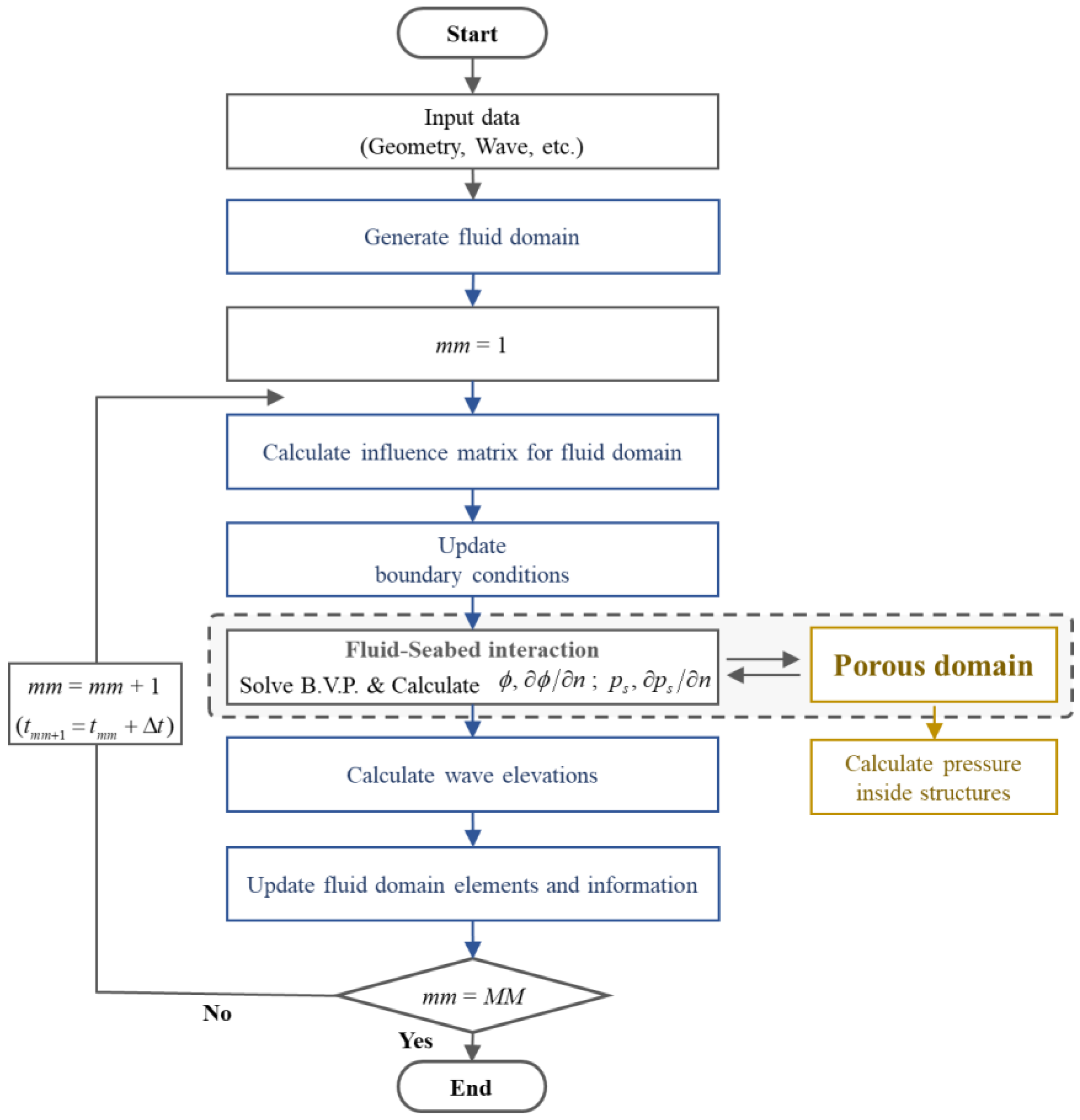
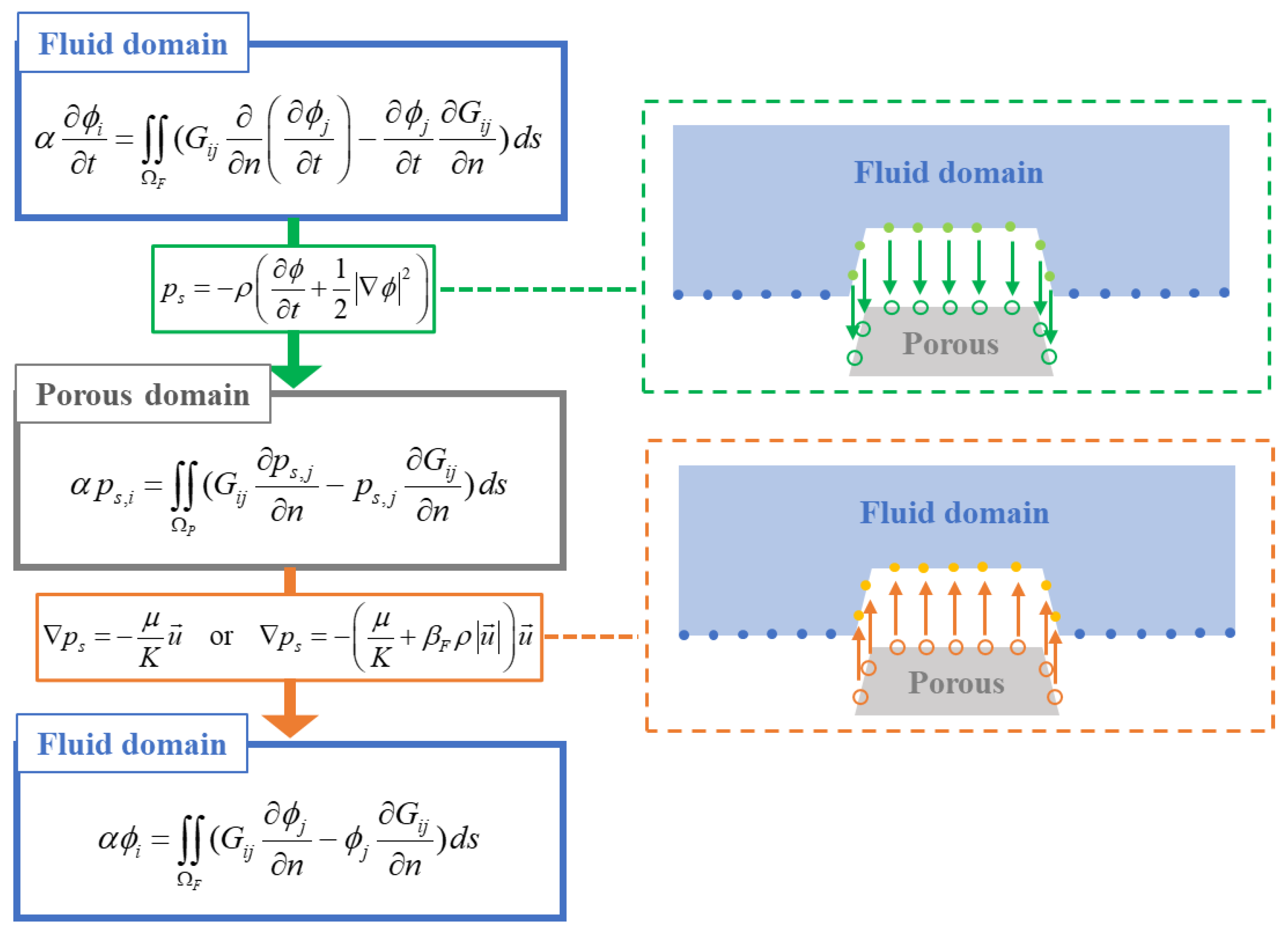
2.3. Numerical Calculation Process and Coupling of Fluid Domain and Porous Domain

Using the fluid and porous medium model described in the above sections, the wave–porous structure interaction was calculated and nodes were rearranged at each time step. The flowchart of the total process is presented in Figure 1.
Figure 2 provides greater detail of “the interaction of the fluid and porous domain” process shown in Figure 1. A three-step calculation scheme [36] was used to calculate the coupling of the fluid and porous domains. First, the boundary value problem (BVP) for the time derivative of velocity potential (∂ϕ/∂t) in the fluid domain is solved, and the obtained values are used as the interface boundary condition (Equation (17)) in the porous domain. The boundary condition for ∂ϕ/∂t on the interface between the fluid and the porous domain is assumed to be Equation (19). Then, the time derivative of ∂ϕ/∂n can be obtained from sub-step values of ∂ϕ/∂n in each time step using the finite difference formula [40] as shown in Equation (20).
n ϕ t = t ϕ n ,
t ϕ ( t m m + 1 ) n = 1 4 Δ t ( 10 ϕ n ( 4 ) 2 ϕ n ( 1 ) 4 ϕ n ( 2 ) 4 ϕ n ( 3 ) ) 1 2 t ϕ ( t m m ) n ,
where ϕn(l) = ∂ϕ(l)/∂n and the superscript (l) mean each sub-step value in the Runge–Kutta 4th order. Second, the BVP for the pore pressure in the porous domain is solved, and the resulting values are used as the interface boundary conditions (Equations (11) and (12)) in the fluid domain. At this time, in the non-Darcy flow boundary conditions, the discharge velocity ( u ) is calculated using an iterative method. Finally, the BVP for the velocity potential is solved again, and the free surface elevation affected by the porous domain can be calculated.
In developing the FN-NWT, the advantage of solving the BVP for the time derivative of velocity potential independently in addition to the BVP of velocity potential itself was well explained as the acceleration potential method in [41]. Alternatively, the time derivative of the velocity potential can be obtained numerically through the backward difference formula, which is not only less accurate but also may cause numerical instability during the time-marching process.

3. Numerical Results and Discussion

3.1. Validation of Numerical Results

The numerical model of this study was compared with experimental data for verification [27]. Figure 3 presents a schematic diagram of a dual porous breakwater. The detailed setup conditions of the numerical model are as follows: water depth (h) = 0.8 m; incident wave height (HI) = 0.04 m; wave period (T) ranges from 1.29 s to 3.73 s. The submerged breakwater was set up under the following conditions: bottom width (Wb) = 2h; top width (Wt) = 0.5h; height (Hb) = 0.5h; distance between structures (Lb) = 3.6 m. The submerged structure was a tetrapod model in an experimental study [27] and its effective diameter (d50) and porosity (n) were 0.076 m and 0.5 m, respectively [28].
First, a convergence test was performed by increasing the number of nodes for the non-porous structure, as shown in Figure 4. The time step was set to Δt = T/64. From Figure 4, if the number of nodes per wavelength is 25 or more, the wave elevation appears to converge. Therefore, in this study, the calculation was performed by setting the number of nodes to Δx = λ/30.
In the reference experimental paper [27], a tetrapod was used to set up the porous breakwater. To obtain the permeability coefficient, the suggested relation between permeability coefficient (K) and the porosity (n) for the tetrapod was used [42].
K = 5 × 10 9 e 7.3 n   [ m 2 ] ,
From Equation (21), the permeability coefficient was set to K = 2.039 × 10⁻⁷ m2 in this study. Additionally, the Forchheimer coefficient was obtained using the empirical formula [43]. This value was a function of effective diameter (d50) and porosity (n), as follows: from Equations (12), (22), and (23), the non-Darcy factor (βF) of the porous structures can be obtained as Equation (24).
p s = ρ g h p = μ K u   ρ g B s u u ,
B s = 0.194325 d 50 1.265175 n 1.141417   [ s 2 / m 2 ] ,
β F = c K = g B s   1 / m ,
where hp means the piezometric head. From the above equations, the non-Darcy factor was set to βF = 109.54/m (c = 0.0495).
Figure 5 and Figure 6 present snapshots of the incident wave elevations over non-porous (rigid) and porous structures. In the case of kh = 1.0, the reflected wave was almost the same regardless of the porosity of the structure, but the transmitted wave was greatly reduced by the porous structure. In Figure 6 (kh = 1.2), both reflected and transmitted wave elevations were reduced by the porous structure. The wave attenuation in the model with the Darcy flow boundary condition was greater than that under the non-Darcy flow condition. The transmitted waves passing over non-porous structures look more deformed from the linear sinusoidal form than those over the porous structures.
Figure 7 compares the wave reflection coefficients with previous experimental and numerical data (Eigenfunction expansion method, EFEM). The present results from the FN-NWT are generally in good agreement with the other datasets for both non-porous and porous structure conditions. For porous structures, the wave reflection coefficients were similar to the previous study data, except in the long wave region (kh = 0.5–0.7). Notably, at the second maximum peak (around kh = 1.3), the wave reflection coefficients applying the non-Darcy (Forchheimer) flow boundary condition (Equation (12)) showed more similar results compared with the experimental and calculation results than the result of applying the Darcy flow boundary condition (Equation (11)). The reduction of the reflected wave amplitude is noticeable, especially at the respective peaks. While Darcy’s method underestimates the reflection coefficient. This is especially the case in the range of kh = 1.2–1.4, where there is a fairly good agreement between the non-Darcy-based FN-NWT and the experimental results. This shows that the non-Darcy approach produces better results than the Darcy-based approach.
Table 1 shows the difference between the present results and previous calculation data [31] for the porous structure case (Figure 7b case). In a low frequency region, the results of the non-Darcy flow condition deviate more from the previous calculation results. However, the error of the results under non-Darcy flow condition was greatly reduced as the wave frequency increased.

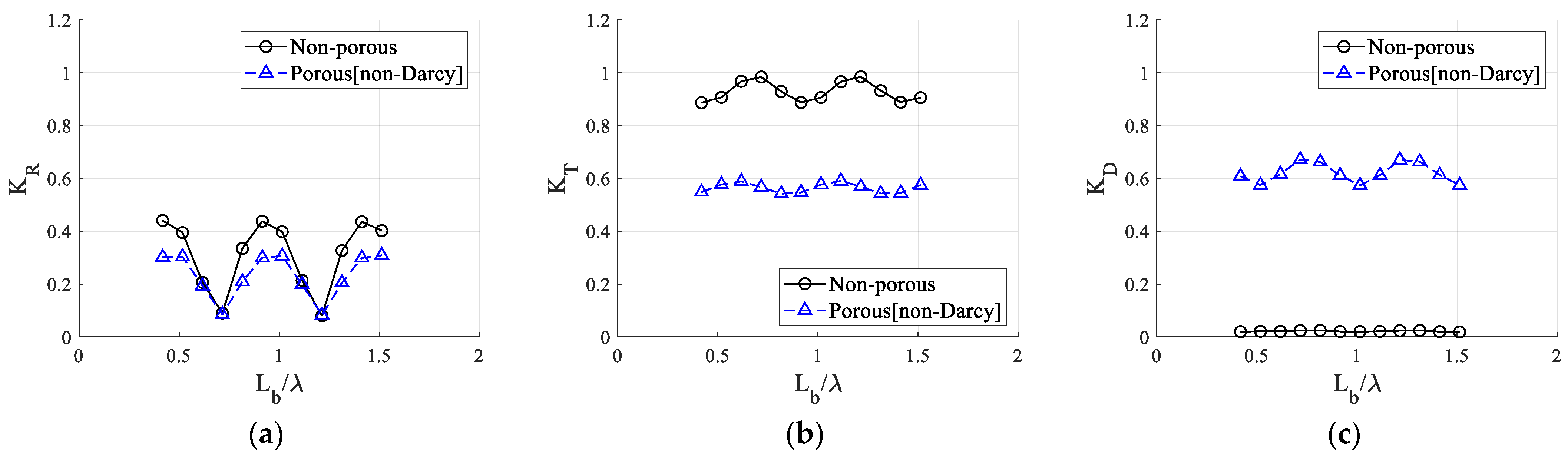
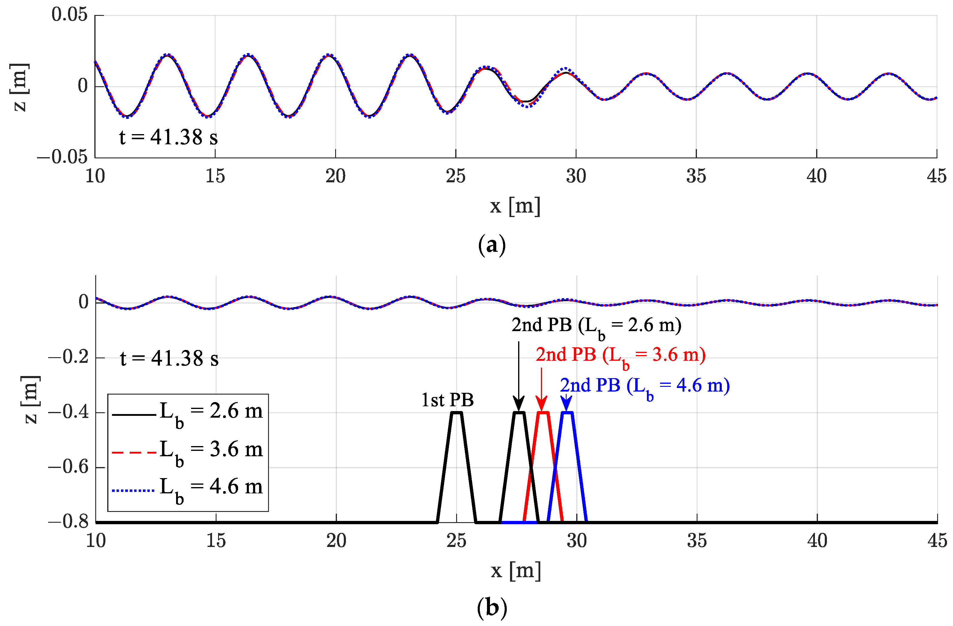
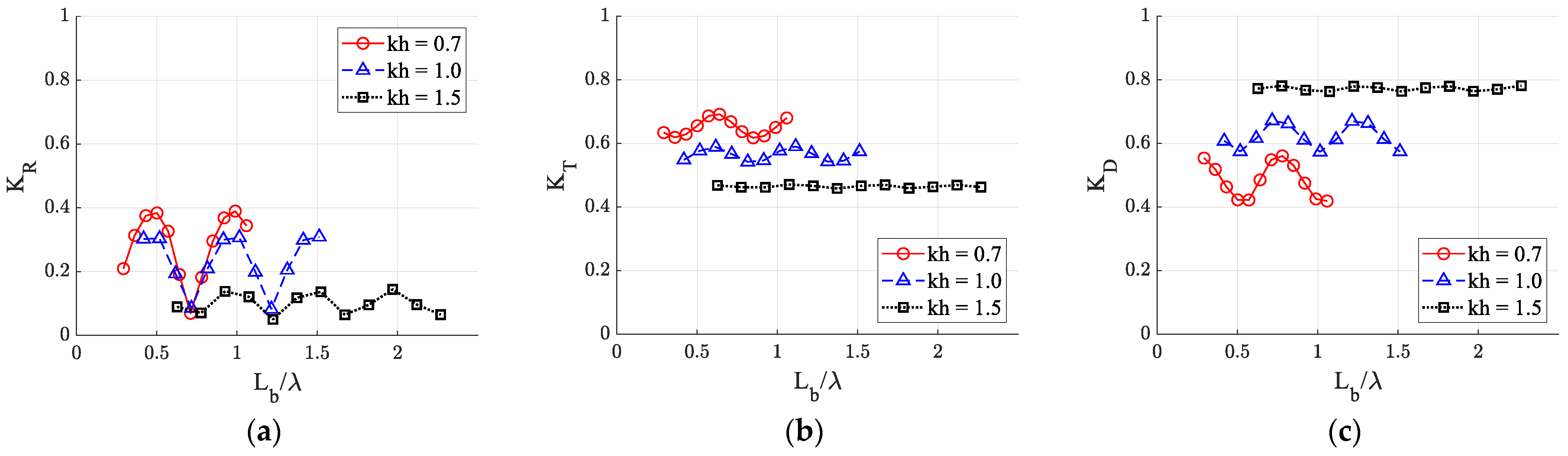
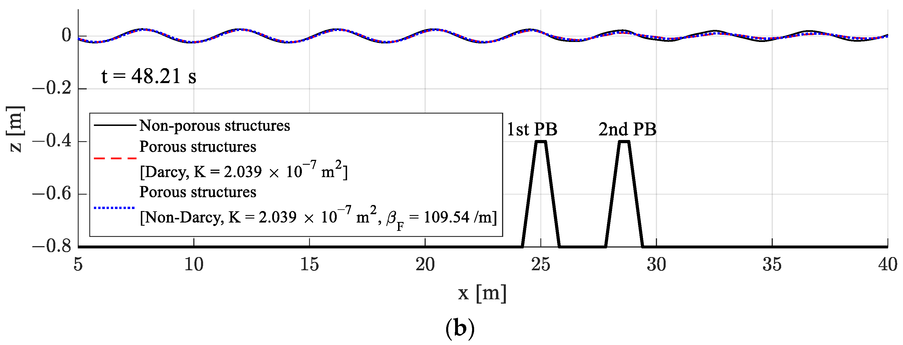
3.2. Comparison of Non-Porous and Porous Structures

Figure 8 compares the wave reflection, transmission, and dissipation coefficients over a submerged non-porous and porous dual breakwater. The results for the porous structures were calculated by applying the non-Darcy flow boundary condition. The wave reflection (KR) and transmission (KT) coefficients are defined as Equations (25) and (26), and these coefficients define the wave dissipation coefficient (KD) [20,30,31].
K R = H R / H I ,
K T = H T / H I ,
K D = 1   ( K R 2 + K T 2 ) ,
where HR and HT mean the wave heights of reflected and transmitted waves, respectively.
When the wave reflection by the non-porous structure was large, the attenuation of the reflected wave by the porous structure was also large. In the non-porous structure, there are fluctuations in the transmission coefficient (kh = 0.5–1.5). In the porous structure, the transmission coefficient continues to decrease, but the decrease is moderate with shorter wavelengths. Then, in case of the non-Darcy flow, the transmission coefficient becomes minimal at about kh = 2.0 and increases slightly with shorter wavelengths. The dissipation coefficient increases markedly in the kh = 0.7–1.0 region, with a maximum of about kh = 2.0 for the non-Darcy flow condition.
The energy dissipation by the non-porous structure was relatively small; however, the energy dissipation by the porous structure was quite large, as intuitively expected. In addition, the porous structure modeling based on the Darcy flow dissipates more energy, which, in turn, results in smaller reflected and transmitted waves. As a result, the wave dissipation coefficient (KD) in the Darcy flow condition was approximately 0.1–0.15 larger than that in the non-Darcy flow condition. Comparisons with previous results show that the non-Darcy model produced better comparisons with the measured data than the Darcy model.
Figure 9 shows the wave reflection, transmission, and dissipation coefficients according to the distance (Lb) between dual structures under constant wavelength conditions (kh = 1.0). Lb is set from 2.1 to 7.6 m. In the non-porous structure, both reflection and transmission coefficients (KR, KT) tend to repeat peaks and troughs at the interval of Lb = 0.5. In case of porous structure, a similar fluctuation is seen with a significant decrease in amplitudes and mean values. Instead, unlike the non-porous case, significant wave energy dissipation can be observed, as shown in KD. It is of interest that the transmission coefficient of the wave passing over the porous dual structure is insensitive to the gap distance. The wave energy dissipation coefficients of the porous case remain around 0.6 over the kh range considered, showing the effectiveness of the applied dual porous breakwater.
Figure 10, Figure 11 and Figure 12 present snapshots of wave elevations according to the distance between two porous (non-Darcy) structures for Lb = 2.6, 3.6 and 4.6 m. The differences in the transmitted waves with varying the distance were not significant.
In Figure 10a, a slight phase difference was observed with different distances between structures at long wave condition in the region of the reflected waves (x = 10–25 m), but the phases of transmitted waves were almost same. The phase shift of reflected waves was less pronounced in shorter waves because seabed structures are less affected by shorter waves. The dimensionless structure spacing normalized by wave length (Lb/λ) was used in Figure 13 for three representative wave lengths.
Figure 13 compares their differences according to wavelength (kh). As the wavelength becomes shorter (kh increases), the difference in each coefficient according to the distance between the dual porous structure was not large (Figure 13). This is because the seabed effect decreases as the water depth increases relative to the wavelength (h/λ). Regardless of wavelength, the values of Lb/λ corresponding to the maximum and minimum values of each coefficient are similar. However, the effect of distance between structures decreased in larger kh (i.e., in deeper water or with shorter wave length). As shown in Figure 8, the dissipation coefficient increases with shorter wavelengths.
Figure 14 compares the wave characteristics for various incident wave heights. The transmission coefficient increased as the incident wave height increased (Figure 14b), while the dissipation coefficient decreased (Figure 14c). However, its effect on the wave reflection coefficient was not significant.
Figure 14 also shows the differences in wave coefficients according to linear and fully nonlinear calculations. As the wave non-linearity increases (the incident wave height increases), the differences in the transmission and dissipation coefficients were observed more clearly, while the reflection coefficients remain similar. When comparing the linear and fully nonlinear results, their differences are noticeable in higher incident wave amplitudes at kh values lower than 0.7.
The snapshots of wave elevations (Figure 15) are compared under the condition of kh = 1.2, where the difference in the wave reflection coefficient is the maximum according to Figure 14a. Figure 15a shows the relative wave elevation to the incident wave height (η/HI). As the wave height increases, the shapes of the reflected waves show slight differences, but the shapes of the transmitted waves are appreciably deformed compared with the linear sinusoidal wave form. More deformation is seen in higher incident waves, as shown in Figure 15a.
The distribution of wave-induced dynamic pressure in the submerged structures is shown in Figure 16. The pressure was made dimensionless by the magnitude of wave dynamic pressure, a value obtained as shown below:
p 0 = ρ g H I 2 cosh ( k h ) ,
Figure 16 shows the pore pressure distribution in the porous structure for large incident wave height (HI = 0.12 m) and kh = 1.2. Figure 16a,b present linear simulation results, and Figure 16c,d show fully nonlinear simulation results. As the wave passes over submerged structures, the deformation of wave shapes and phases by the submerged structures leads to differences in the pore pressure distribution between linear and fully nonlinear cases. The pressure magnitude/fluctuation of the of the front structure is generally higher than that of the rear structure. The pressure differences between the linear and nonlinear cases are also more noticeable at the rear structure due to more wave deformations after passing the front structure in the fully nonlinear results.
Based on previous studies, applying Darcy’s flow boundary condition was sufficiently valid under small permeability conditions [36]. In the case of relatively high permeability, however, more accurate results can be obtained by applying the non-Darcy flow boundary condition, especially in short wave regions, as illustrated in Figure 6. When the flow in the highly porous structures was assumed to be Darcy flow, the reflected and transmitted waves were greatly attenuated, which implies greater wave dissipation than in the non-Darcy flow case. In general, when the porous structure was used, the fluctuations of reflection and transmission coefficients corresponding to the wavelengths or the distances between dual structures were reduced. The effect of the porous structure was greater for transmitted waves than reflected waves, and more wave energy was dissipated when using the porous structure. However, the transmission coefficients were relatively insensitive to the gap distances.
In addition, by using the developed dual-domain FN-NWT, the nonlinear deformations of transmitted waves by the porous dual structure were clearly observed. As the incident wave height increased, more nonlinear wave deformations were observed due to higher nonlinear effects. The present dual-domain FN-NWT was based on potential flow theory. More realistic physics can be described by using the CFD model in the porous region. However, it is difficult to reproduce the details of the complex flows with many rubles and numerous sub-element structures, even with the advanced CFD programs consuming several orders higher computational effort and time. In this regard, the developed dual-domain FN-NWT can practically be applied as a first-cut design tool.

4. Conclusions

In this study, a fully nonlinear numerical wave tank (FN-NWT) with a porous domain was developed to analyze wave propagation characteristics over submerged porous breakwaters. A three-step calculation process was devised to accurately reflect the interaction between the dual domains. The Darcy and Forchheimer (non-Darcy) flow conditions were used as the fluid and porous interface boundary conditions in the time domain analysis. In the submerged porous structures, the non-Darcy flow model performed better against the corresponding experimental and previous calculation results than the Darcy flow model, as the wavelength became shortened. The wave transmission coefficient of the submerged porous structure was reduced significantly compared with that of the non-porous structure. In particular, applying the Darcy flow condition resulted in greater excessive wave attenuation than non-Darcy flow condition. In the non-Darcy flow condition, the energy dissipation by the submerged porous breakwater increased, with kh reaching a maximum at kh = 2. As the wavelength became shorter (kh increased), the reflection and transmission coefficients decreased with increased energy dissipation regardless of structure spacing. As the incident wave height increased, the transmission coefficient grew relatively larger. The difference between linear and fully nonlinear results was more pronounced at a low frequency (small kh values). The present FN-NWT can also calculate pressure distribution inside the porous breakwater and the resultant forces against it exerted by nonlinear waves.
The present FN-NWT, coupled with the fluid and porous medium domain at each time step and the application of a three-step calculation scheme, can simulate the nonlinear wave and porous structure interaction, even for a relatively large permeability coefficient. Although the FN-NWT has limitations as a two-dimensional potential flow model, it can sufficiently analyze the characteristics of typical long-crested reflected and transmitted waves, thereby saving computational effort and time. The methodology developed in this study can also be easily extended to the three-dimensional model. The FN-NWT model can be applied to various bottom geometries, tsunamis, and irregular waves.

Author Contributions

Conceptualization, E.-H.M. and W.K.; methodology, E.-H.M. and W.K.; software, E.-H.M. and W.K.; validation, E.-H.M.; formal analysis, E.-H.M. and W.K.; investigation, E.-H.M. and W.K.; writing—original draft preparation, E.-H.M.; writing—review and editing, E.-H.M., M.-H.K. and W.K.; supervision, M.-H.K. and W.K.; project administration, W.K.; funding acquisition, W.K. All authors have read and agreed to the published version of the manuscript.

Funding

This work was supported by INHA UNIVERSITY Research Grant.

Institutional Review Board Statement

Not applicable.

Informed Consent Statement

Not applicable.

Data Availability Statement

Not applicable.

Conflicts of Interest

The authors declare no conflict of interest.

References

  1. Cuong, D.Q.; Tuan, T.Q. Wave hydrodynamics across steep platform reefs: A laboratory study. Civ. Eng. J. 2022, 8, 1739–1751. [Google Scholar] [CrossRef]
  2. Safari Ghaleh, R.; Aminoroayaie Yamini, O.; Mousavi, S.H.; Kavianpour, M.R. Numerical Modeling of Failure Mechanisms in Articulated Concrete Block Mattress as a Sustainable Coastal Protection Structure. Sustainability 2021, 13, 12794. [Google Scholar] [CrossRef]
  3. Srineash, V.K.; Murali, K. Effects of seaward slope on wave transmission of porous and non-porous reef breakwaters with smooth and stepped slopes. Coast. Struct. 2019, 2019, 275–285. [Google Scholar]
  4. Chyon, M.S.A.; Rahman, A.; Rahman, M.A. Comparative study on hydrodynamic performance of porous and non-porous submerged breakwater. Procedia Eng. 2017, 194, 203–210. [Google Scholar] [CrossRef]
  5. Mojtahedi, A.; Beiragh, M.S.; Farajpour, I.; Mohammadian, M. Investigation on hydrodynamic performance of an environmentally friendly pile breakwater. Ocean Eng. 2020, 217, 107942. [Google Scholar] [CrossRef]
  6. Widyastuti, I.; Thaha, M.A.; Lopa, R.T.; Hatta, M.P. Dam-break energy of porous structure for scour countermeasure at bridge abutment. Civ. Eng. J. 2022, 8, 3939–3951. [Google Scholar] [CrossRef]
  7. Mizutani, N.; Mostafa, A.M.; Iwata, K. Nonlinear regular waves, submerged breakwater and seabed dynamic interaction. Coast. Eng. 1998, 33, 177–202. [Google Scholar] [CrossRef]
  8. Mostafa, A.M.; Mizutani, N.; Iwata, K. Nonlinear wave, composite breakwater, and seabed dynamic interaction. J. Waterw. Port Coast. Ocean Eng. 1999, 236, 88–97. [Google Scholar] [CrossRef]
  9. Ranasinghe, R.S.; Sata, S.; Tajima, Y. Modeling of waves & currents around porous submerged breakwaters. Proc. Coast. Dyn. 2009, 2009, 1–13. [Google Scholar]
  10. Hieu, P.D.; Vinh, P.N. Numerical study of wave overtopping of a seawall supported by porous structures. Appl. Math. Model. 2012, 36, 2803–2813. [Google Scholar] [CrossRef]
  11. Lee, J.; Jeong, Y.M.; Kim, J.S.; Hur, D.S. Analysis of hydraulic characteristics according to the cross-section changes in submerged rigid vegetation. J. Ocean Eng. Technol. 2022, 36, 326–339. [Google Scholar] [CrossRef]
  12. Jeng, D.-S.; Ye, J.-H.; Zhang, J.-S.; Liu, P.L.-F. An integrated model for the wave-induced seabed response around marine structures: Model verifications and applications. Coast. Eng. 2013, 72, 1–19. [Google Scholar] [CrossRef]
  13. Ye, J.; Yu, D. ABAQUS-OlaFlow integrated numerical model for fluid-seabed-structure interaction. Mar. Struct. 2021, 78, 103016. [Google Scholar] [CrossRef]
  14. Dentale, F.; Donnarumma, G.; Carratelli, E.P. Numerical wave interaction with tetrapods breakwater. Int. J. Nav. Archit. Ocean Eng. 2014, 6, 800–812. [Google Scholar] [CrossRef]
  15. Zhang, T.; Zhao, Y.; Gan, Q.; Yuan, L.; Zhu, G.; Cai, Y.; Cao, B. Experimental investigation of Forchheimer coefficients for non-Darcy flow in conglomerate-confined aquifer. Geofluids 2018, 2018, 4209197. [Google Scholar] [CrossRef]
  16. Wang, D.X.; Dong, S.; Sun, J.W. Numerical modeling of the interactions between waves and a Jarlan-type caisson breakwater using OpenFOAM. Ocean Eng. 2019, 188, 106230. [Google Scholar] [CrossRef]
  17. Han, M.M.; Wang, C.M. Potential flow theory-based analytical and numerical modelling of porous and perforated breakwater: A review. Ocean Eng. 2022, 249, 110897. [Google Scholar] [CrossRef]
  18. Jeong, J.H.; Kim, J.H.; Lee, J.L. Analysis of wave transmission characteristics on the TTP submerged breakwater using a parabolic-type linear wave deformation model. J. Ocean Eng. Technol. 2021, 35, 82–90. [Google Scholar] [CrossRef]
  19. Behera, H.; Koley, S.; Sahoo, T. Wave transmission by partial porous structures in two-layer fluid. Eng. Anal. Bound. Elem. 2015, 58, 58–78. [Google Scholar] [CrossRef]
  20. Koley, S. Wave transmission through multilayered porous breakwater under regular and irregular incident waves. Eng. Anal. Bound. Elem. 2019, 108, 393–401. [Google Scholar] [CrossRef]
  21. Tabssum, S.; Kaligatla, R.B.; Sahoo, T. Gravity wave interaction with a porous breakwater in a two-layer ocean of varying depth. Ocean Eng. 2020, 196, 106816. [Google Scholar] [CrossRef]
  22. Tabssum, S.; Kaligatla, R.B.; Sahoo, T. Surface gravity wave interaction with a partial porous breakwater in the presence of bottom undulation. J. Eng. Mech. 2020, 146, 04020088. [Google Scholar] [CrossRef]
  23. Chen, K.H.; Chen, J.T.; Lin, S.Y.; Lee, Y.T. Dual boundary element analysis of normal incident wave passing a thin submerged breakwater with rigid, absorbing, and permeable boundaries. J. Waterw. Port Coast. Ocean Eng. 2004, 130, 179–190. [Google Scholar] [CrossRef]
  24. Han, M.M.; Wang, C.M. Modelling wide perforated breakwater with horizontal silts using Hybrid-BEM method. Ocean Eng. 2021, 222, 108630. [Google Scholar] [CrossRef]
  25. Duan, W.Y.; Liu, R.Z.; Chen, J.K.; Ma, S. Hydrodynamic analysis of floating breakwater with perforated structure based on the Taylor expansion boundary element method. Ocean Eng. 2020, 200, 107044. [Google Scholar] [CrossRef]
  26. Mizutani, N.; McDougal, W.; Mostafa, A. BEM-FEM combined analysis of nonlinear interaction between wave and submerged breakwater. Coast. Eng. 1997, 1996, 2377–2390. [Google Scholar]
  27. Cho, Y.S.; Lee, J.I.; Kim, Y.T. Experimental study of strong reflection of regular water waves over submerged breakwaters in tandem. Ocean Eng. 2004, 31, 1325–1335. [Google Scholar] [CrossRef]
  28. Jeon, C.H.; Cho, Y.S. Bragg reflection of sinusoidal waves due to trapezoidal submerged breakwaters. Ocean Eng. 2006, 33, 2067–2082. [Google Scholar] [CrossRef]
  29. Zhao, Y.; Liu, Y.; Li, H.; Chang, A. Oblique wave motion over multiple submerged porous bars near a vertical wall. J. Ocean Univ. China 2017, 16, 568–574. [Google Scholar] [CrossRef]
  30. Khan, M.B.M.; Behera, H. Oblique wave scattering by double porous structures. J. Phys. Conf. Ser. 2018, 1000, 012168. [Google Scholar] [CrossRef]
  31. Behera, H.; Khan, M.B.M. Numerical modeling for wave attenuation in double trapezoidal porous structures. Ocean Eng. 2019, 184, 91–106. [Google Scholar] [CrossRef]
  32. Jiang, L.; Zhang, J.; Tong, L.; Guo, Y.; He, R.; Sun, K. Wave motion and seabed response around a vertical structure sheltered by submerged breakwaters with Fabry-Pérot resonance. J. Mar. Sci. Eng. 2022, 10, 1797. [Google Scholar] [CrossRef]
  33. Zhao, E.; Dong, Y.; Tang, Y.; Xia, X. Performance of submerged semi-circular breakwater under solitary wave in consideration of porous media. Ocean Eng. 2021, 223, 108573. [Google Scholar] [CrossRef]
  34. Zhu, K.; Jiang, R.; Sun, Z.; Qin, H.; Cheng, Z.; Wang, Y.; Zhao, E. Numerical study on the effects of the multiple porous medium breakwaters on the propagation of the solitary wave. J. Mar. Sci. Eng. 2023, 11, 565. [Google Scholar] [CrossRef]
  35. Min, E.H.; Koo, W. Numerical simulation of wave propagation over structures on a porous seabed. J. Coast. Res. 2018, 85, 966–970. [Google Scholar] [CrossRef]
  36. Min, E.H.; Koo, W. Numerical analysis of nonlinear wave characteristics under porous sloped-seabed conditions. J. Coast. Res. 2021, 114, 116–120. [Google Scholar] [CrossRef]
  37. Chwang, A.T.; Chan, A.T. Interaction between porous media and wave motion. Annu. Rev. Fluid Mech. 1998, 30, 53–84. [Google Scholar] [CrossRef]
  38. Longuet-Higgins, M.S.; Cokelet, E. The deformation of steep surface waves on water-I. A numerical method of computation. Proc. R. Soc. Lond. A Math. Phys. Sci. 1976, 350, 1–26. [Google Scholar]
  39. Hou, X.; Shi, W.; Yang, T. A nonlinear flow model for the flow behavior of water inrush induced by the karst collapse column. RSC Adv. 2018, 8, 1656–1665. [Google Scholar] [CrossRef] [PubMed]
  40. Hong, S.Y.; Kim, M.H. Nonlinear wave forces on a stationary cylinder by HOBEM-NWT. In Proceedings of the 10th ISOPE International Ocean and Polar Engineering Conference, Seattle, WA, USA, 27 May–2 June 2000; Volume 3, pp. 214–220. [Google Scholar]
  41. Koo, W.C.; Kim, M.H. Fully nonlinear wave-body interaction with surface-piercing bodies. Ocean Eng. 2007, 34, 1000–1012. [Google Scholar] [CrossRef]
  42. Conzelmann, N.A.; Partl, M.N.; Clemens, F.J.; Müller, C.R.; Poulikakos, L.D. Effect of artificial aggregate shape on the porosity, tortuosity and permeability of their packings. Powder Technol. 2022, 397, 117019. [Google Scholar] [CrossRef]
  43. Sidiropoulou, M.G.; Moutsopoulos, K.N.; Tsihrintzis, V.A. Determination of Forchheimer equation coefficients a and b. Hydrol. Process. 2007, 21, 534–554. [Google Scholar] [CrossRef]
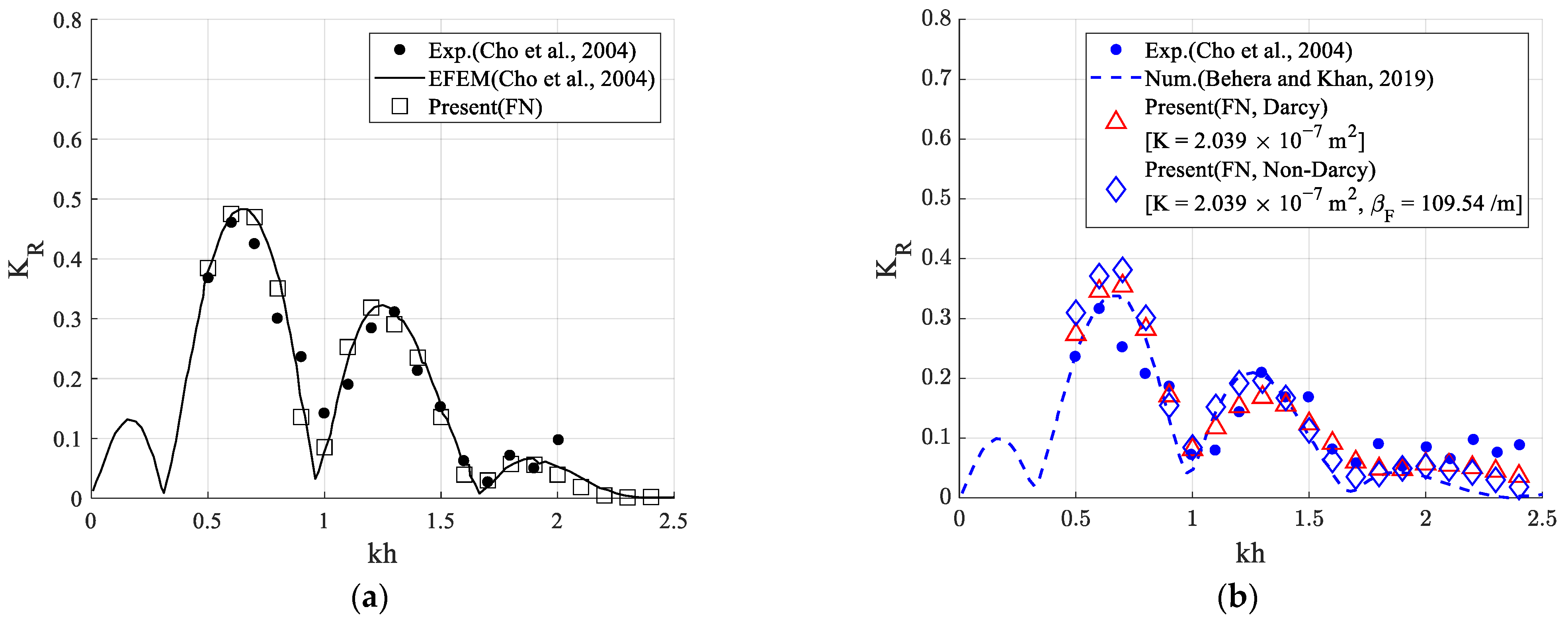
Figure 1. Flow chart of total process for coupling dual domains.
Jmse 11 01648 g001
Figure 2. Three-step calculation process for the interaction between the fluid and porous domains.
Jmse 11 01648 g002
Figure 3. Sketch of a submerged dual porous breakwater (PB: Porous Breakwater).
Jmse 11 01648 g003
Figure 4. Convergence test with increasing number of nodes for the non-porous dual breakwater [HI = 0.04 m, Lb = 3.6 m, kh = 1.0, T = 2.06 s]: (a) Enlarged wave elevation; (b) Simulation overview.
Jmse 11 01648 g004
Figure 5. Snapshots of the wave deformation over a submerged dual breakwater [HI = 0.04 m, Lb = 3.6 m, kh = 1.0, T = 2.06 s]: (a) Enlarged wave elevation; (b) Simulation overview.
Jmse 11 01648 g005
Figure 6. Snapshots of the wave deformation over a submerged dual breakwater [HI = 0.04 m, Lb = 3.6 m, kh = 1.2, T = 1.79 s]: (a) Enlarged wave elevation; (b) Simulation overview.
Jmse 11 01648 g006aJmse 11 01648 g006b
Figure 7. Wave reflection coefficient by a submerged dual breakwater [HI = 0.04 m, Lb = 3.6 m]: (a) Non-porous structures; (b) Porous structures [27,31].
Jmse 11 01648 g007
Figure 8. Comparison of wave reflection, transmission, and dissipation coefficients for the non-porous (rigid) and porous breakwater [HI = 0.04 m, Lb = 3.6 m]: (a) Wave reflection coefficient (KR); (b) Wave transmission coefficient (KT); (c) Wave dissipation coefficient (KD).
Jmse 11 01648 g008
Figure 9. Comparison of the reflection, transmission, and dissipation coefficients between the non-porous and porous structures [Non-Darcy flow (K = 2.039 × 10⁻⁷ m2, βF = 109.54/m)] for the distance between structures [HI = 0.04 m, kh = 1.0]: (a) Wave reflection coefficient (KR); (b) Wave transmission coefficient (KT); (c) Wave dissipation coefficient (KD).
Jmse 11 01648 g009
Figure 10. Comparison of the wave deformation over a submerged dual breakwater according to the distance between dual breakwaters [Non-Darcy flow (K = 2.039 × 10⁻⁷ m2, βF = 109.54/m), HI = 0.04 m, kh = 0.7, T = 2.76 s]: (a) Enlarged wave elevation; (b) Simulation overview.
Jmse 11 01648 g010
Figure 11. Comparison of the wave deformation over a submerged dual breakwater according to the distance between dual breakwaters [Non-Darcy flow (K = 2.039 × 10⁻⁷ m2, βF = 109.54/m), HI = 0.04 m, kh = 1.0, T = 2.06 s]: (a) Enlarged wave elevation; (b) Simulation overview.
Jmse 11 01648 g011
Figure 12. Comparison of the wave deformation over a submerged dual breakwater according to the distance between dual breakwaters [Non-Darcy flow (K = 2.039 × 10⁻⁷ m2, βF = 109.54/m), HI = 0.04 m, kh = 1.5, T = 1.54 s]: (a) Enlarged wave elevation; (b) Simulation overview.
Jmse 11 01648 g012
Figure 13. Comparison of the reflection, transmission, and dissipation coefficients by porous [Non-Darcy flow (K = 2.039 × 10⁻⁷ m2, βF = 109.54/m), HI = 0.04 m] structures for various wavelength (kh): (a) Wave reflection coefficient (KR); (b) Wave transmission coefficient (KT); (c) Wave dissipation coefficient (KD).
Jmse 11 01648 g013
Figure 14. Comparison of the reflection, transmission, and dissipation coefficients between dual porous [Non-Darcy flow (K = 2.039 × 10⁻⁷ m2, βF = 109.54/m), Lb = 3.6 m] structures for various incident wave heights (HI): (a) Wave reflection coefficient (KR); (b) Wave transmission coefficient (KT); (c) Wave dissipation coefficient (KD).
Jmse 11 01648 g014
Figure 15. Snapshots of wave propagation over dual porous structures for various incident wave heights (HI) [Non-Darcy flow (K = 2.039 × 10⁻⁷ m2, βF = 109.54/m), Lb = 3.6 m, kh = 1.2, T = 1.79 s]: (a) Relative wave elevation (z/HI); (b) Simulation overview.
Jmse 11 01648 g015
Figure 16. Snapshots of wave propagation and distributions of wave-induced pore pressure in dual porous structures [Non-Darcy flow (K = 2.039 × 10⁻⁷ m2, βF = 109.54/m), Lb = 3.6 m, HI = 0.12 m, kh = 1.2, T = 1.79 s]: (a) Linear calculation (t = 48.10 s); (b) Linear calculation (t = 49.00 s); (c) Fully nonlinear calculation (t = 48.10 s); (d) Fully nonlinear calculation (t = 49.00 s).
Jmse 11 01648 g016
Table 1. Difference between present and previous calculation data [31] for porous structures.
KhPrevious—Present [Darcy]Previous—Present [Non-Darcy]
0.6−6.93%−14.79%
1.224.87%5.64%
1.317.83%4.20%
1.46.56%−0.50%
Disclaimer/Publisher’s Note: The statements, opinions and data contained in all publications are solely those of the individual author(s) and contributor(s) and not of MDPI and/or the editor(s). MDPI and/or the editor(s) disclaim responsibility for any injury to people or property resulting from any ideas, methods, instructions or products referred to in the content.

