
BEM Turbine Model and PID Control System of a Floating Hybrid Wind and Current Turbines Integrated Generator System


Abstract
:1. Introduction
2. Materials and Methods
2.1. Introduction to Turbine Modeling Using Blade Element Momentum Theory
2.2. Application of Blade Element Momentum Theory
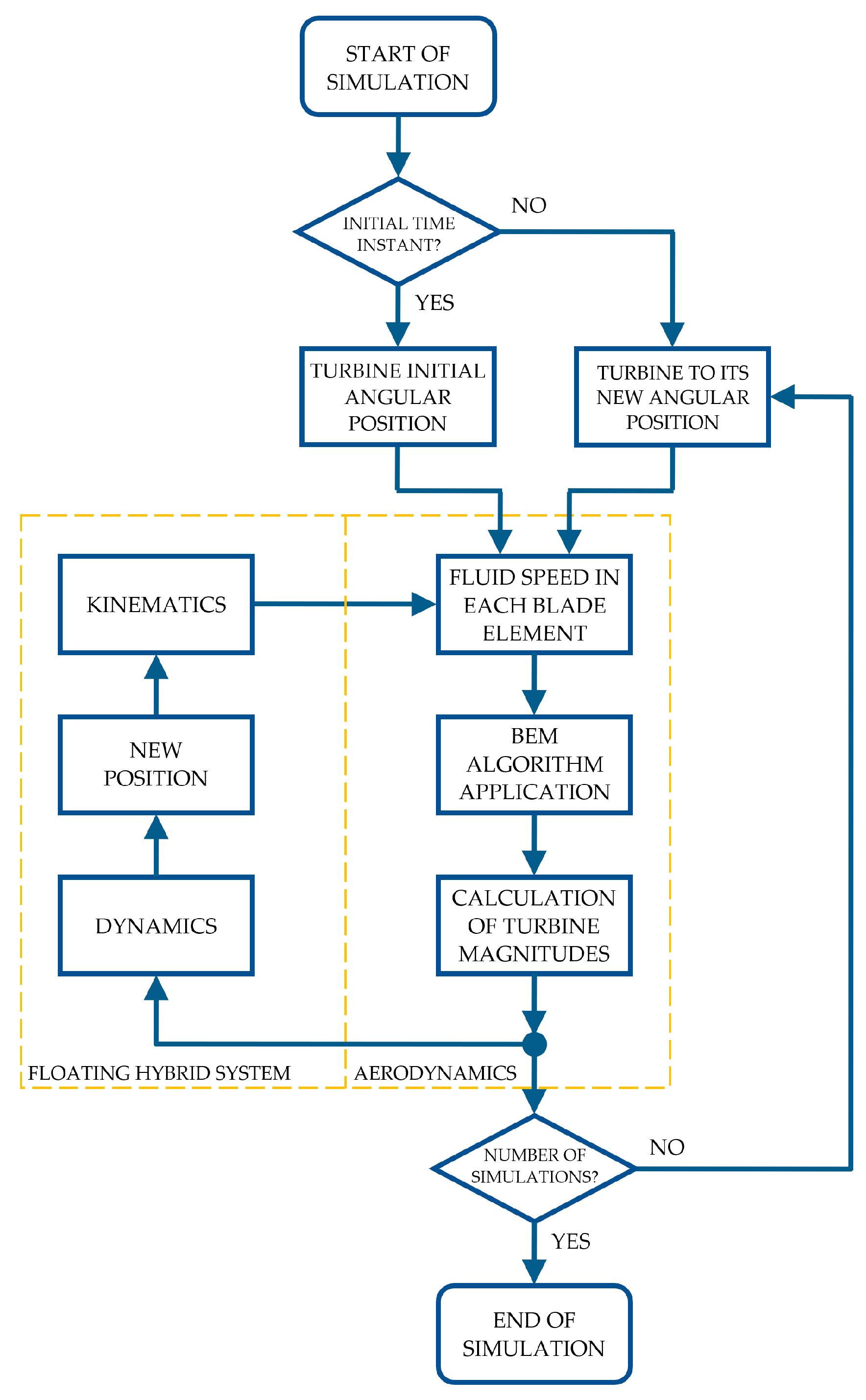
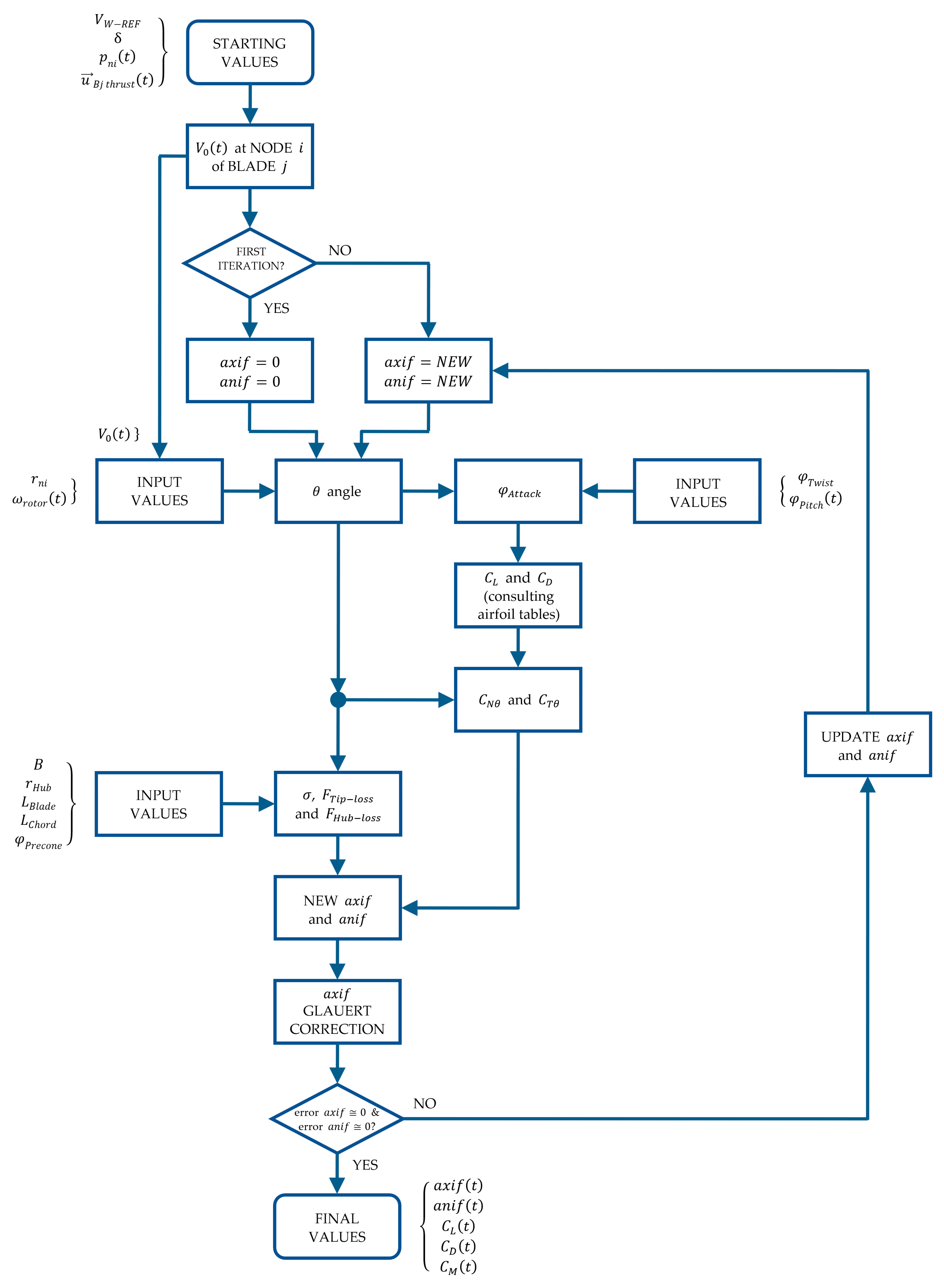
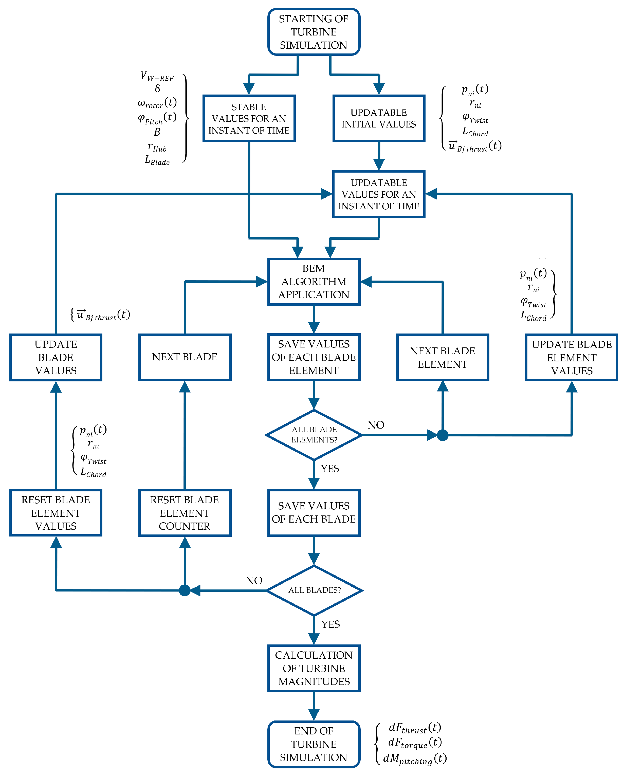
2.2.1. BEM Algorithm Application
2.3. Obtaining Values of the Wind Turbine Magnitudes
2.3.1. Moment about the Shaft
2.3.2. Blade Azimuth Position
2.3.3. Vector of Wind Turbine Forces
2.3.4. Additional Magnitudes
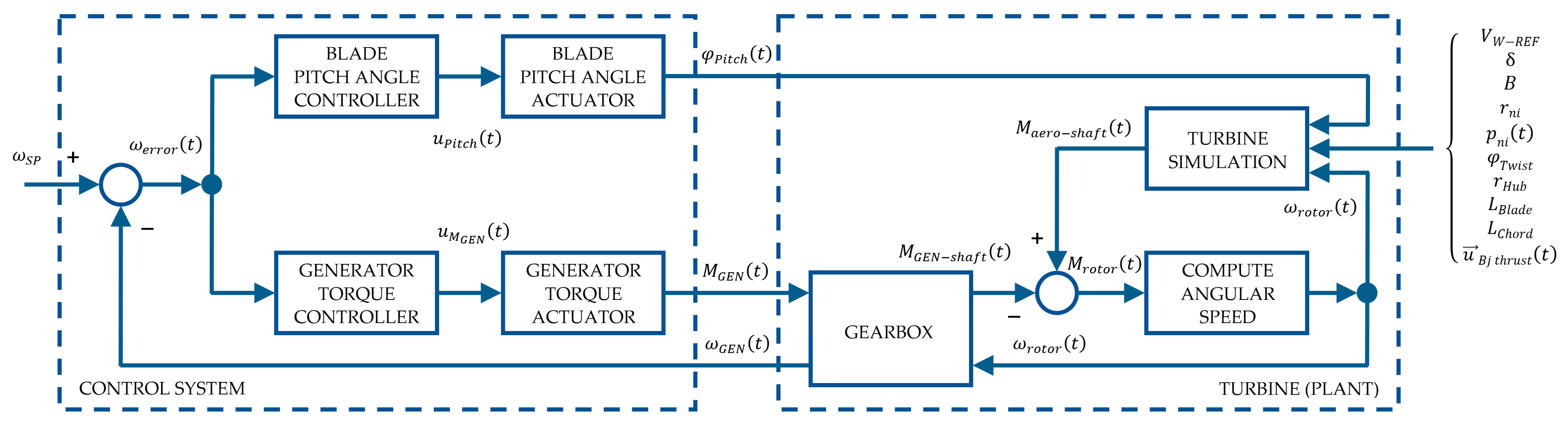
2.4. Wind Turbine Control System
2.4.1. Generator Torque Controller
2.4.2. Collective Blade Pitch Angle Controller
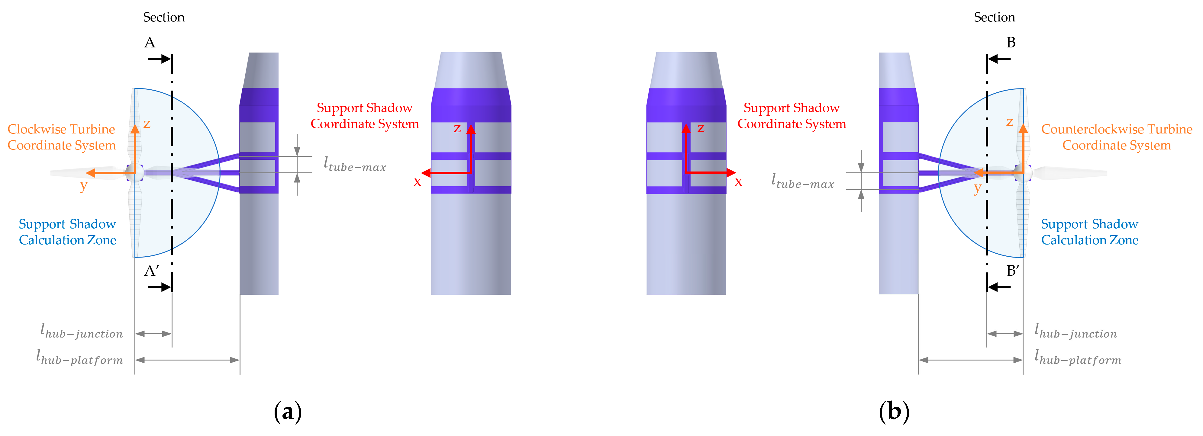
2.5. Application of BEM Modeling to Marine Current Turbines
2.6. Marine Current Turbines Control System
3. Results
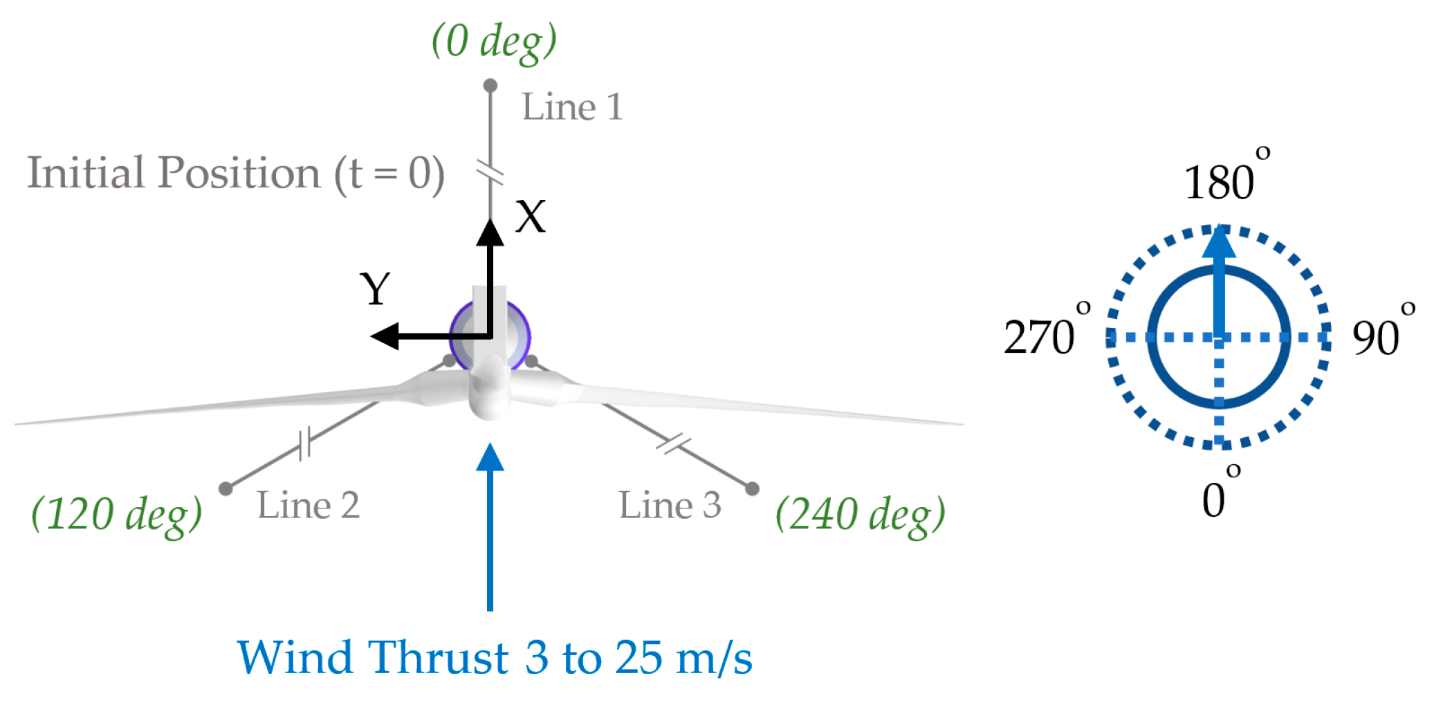
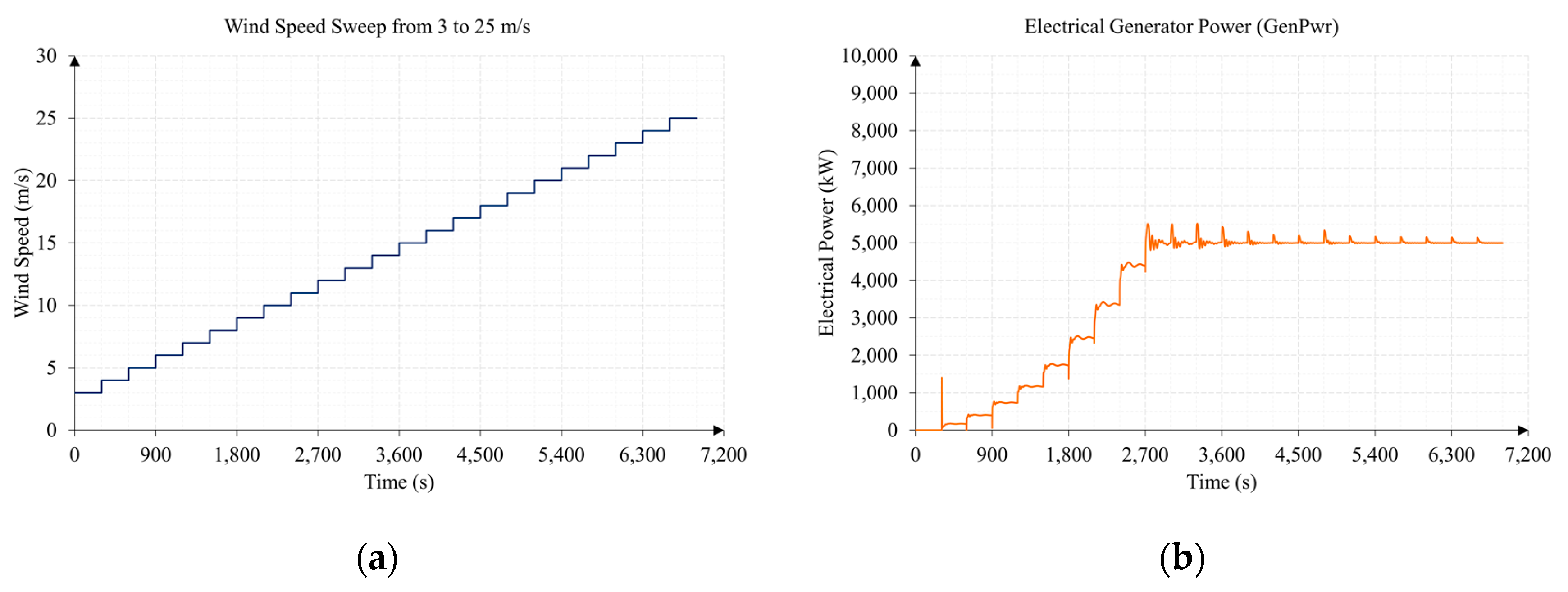
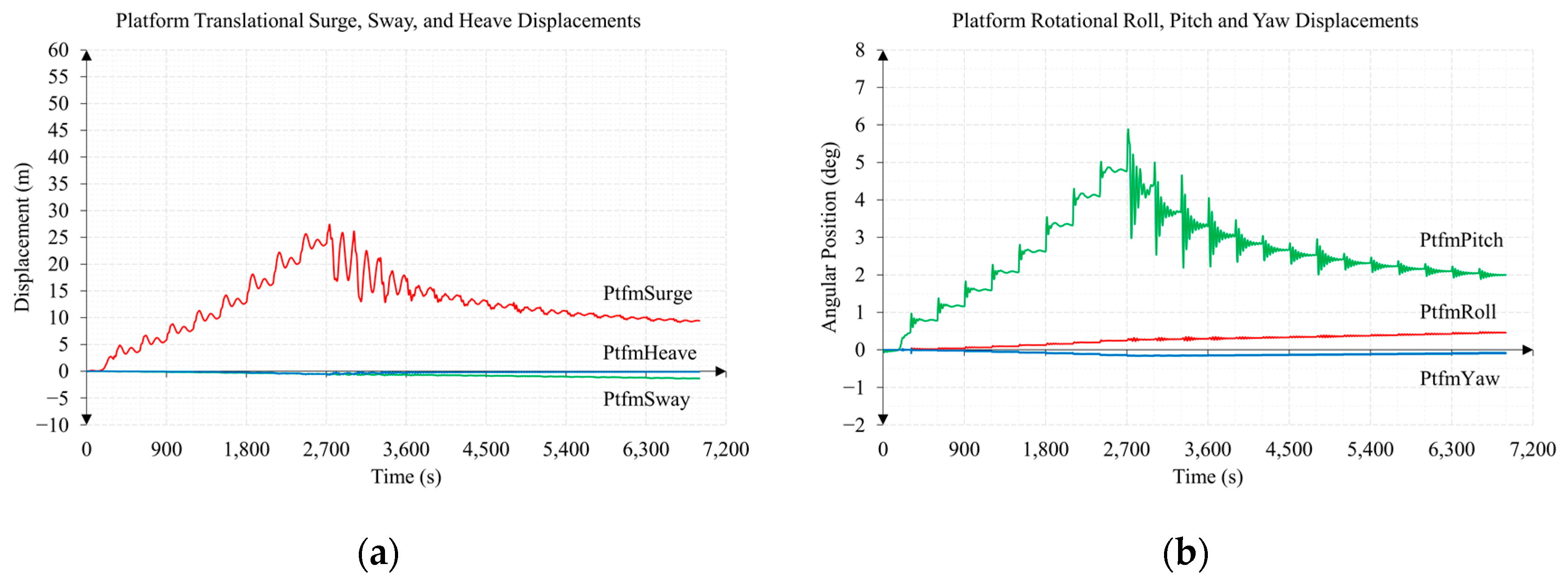
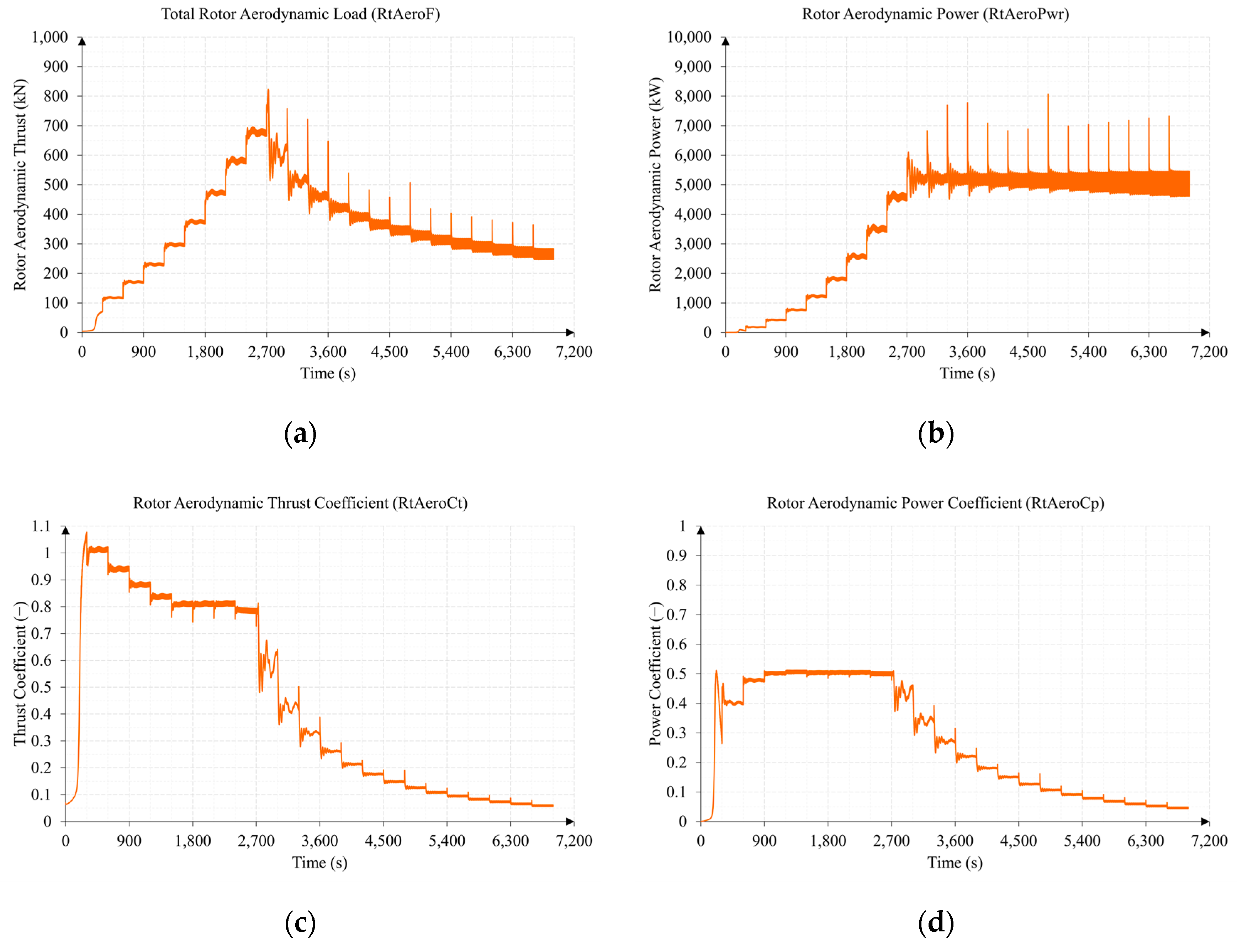
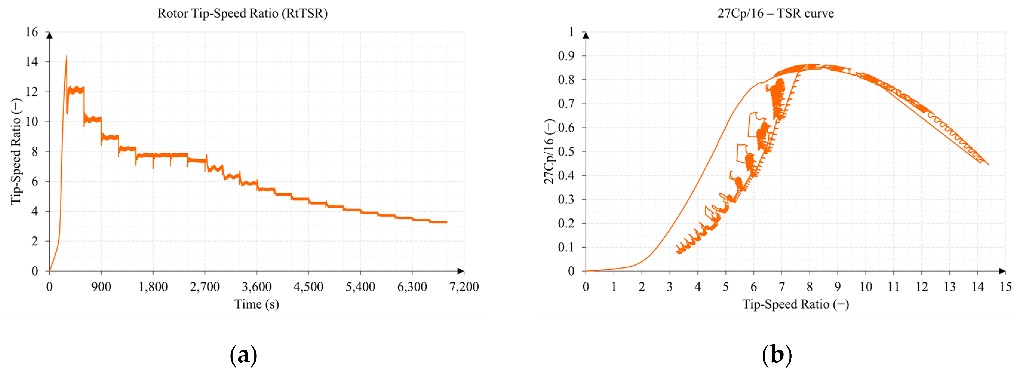
3.1. Test 1. Wind Speed Sweep from 3 to 25 m/s
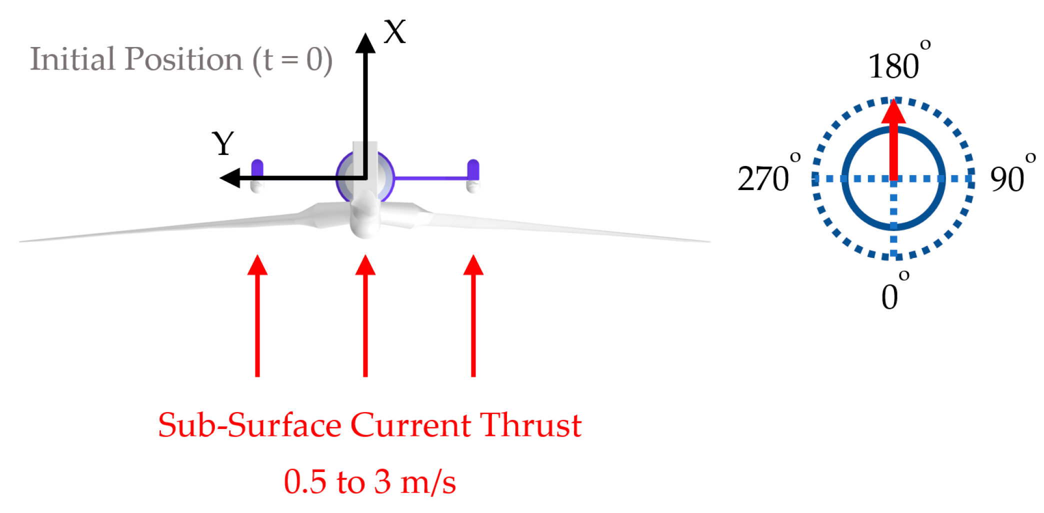
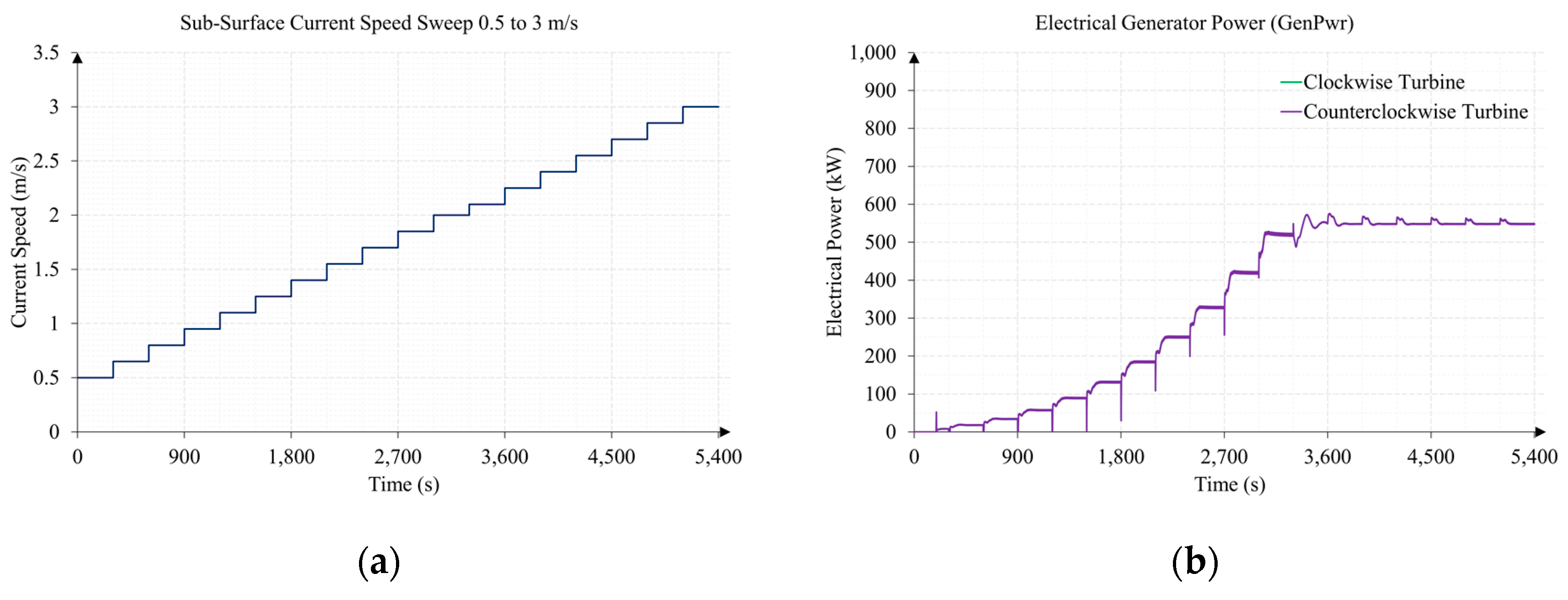
3.2. Test 2. Sub-Surface Current Speed Sweep from 0.5 to 3 m/s
3.3. Comparison of Mooring Line Tensions between Tests 1 and 2
4. Discussion
Supplementary Materials
Author Contributions
Funding
Institutional Review Board Statement
Informed Consent Statement
Data Availability Statement
Acknowledgments
Conflicts of Interest
Abbreviations
| Acronym list | |
| ANSYS | Swanson Analysis Systems |
| BEM | Blade Element Momentum theory |
| CFD | Computational Fluid Dynamics |
| DOF | Degrees Of Freedom |
| FAST | Fatigue, Aerodynamics, Structures, and Turbulence |
| FHYGSYS | Floating Hybrid Generator SYstems Simulator |
| HAWC2 | Horizontal Axis Wind turbine simulation Code 2nd generation |
| HAWT | Horizontal Axis Wind Turbine |
| MCT | Marine Current Turbines |
| MIMO | Multi-Input Multi-Output |
| NREL | National Renewable Energy Lab |
| OC3 | Offshore Code Comparison Collaboration |
| OLAF | cOnvecting LAgrangian Filaments |
| OWT | Offshore Wind Turbines |
| PID | Proportional–Integral–Derivative |
| PLC | Programmable Logic Controller |
| RTHS | Real-Time Hybrid Simulation |
| SHYFEM | System of HYdrodynamic Finite Element Modules |
| SOWFA | Simulator for Wind Farm Applications |
| WRP | WAMIT Reference Point |
| Symbol List | |
| angular induction factor of the wind turbine (or marine current turbine) | |
| mean value of angular induction factor | |
| area of the wind turbine (or marine current turbine) | |
| axial induction factor of the wind turbine (or marine current turbine) | |
| mean value of axial induction factor | |
| value of Glauert correction whose value is 1/3 | |
| low-speed shaft angular acceleration of the turbine rotor | |
| power law exponent | |
| aerodynamic (or hydrodynamic) drag coefficient | |
| aerodynamic (or hydrodynamic) lift coefficient | |
| aerodynamic (or hydrodynamic) normal coefficient | |
| center of mass of the wind turbine | |
| center of mass of the wind turbine expressed in the mobile coordinate system | |
| power coefficient | |
| thrust coefficient | |
| aerodynamic (or hydrodynamic) tangential coefficient | |
| tower diameter to calculate the vector | |
| value To calculate the shadow effect in a marine current turbine | |
| resultant of the differential forces of blade element of blade expressed in the mobile coordinate system | |
| differential of thrust force | |
| differential of thrust force of blade element of blade | |
| differential of thrust force vector of blade element of blade expressed in the mobile coordinate system | |
| differential of torque force | |
| differential of torque force of blade element of blade | |
| differential of torque force vector of blade element of blade expressed in the mobile coordinate system | |
| resultant of the differential moments of blade element of blade expressed in the mobile coordinate system | |
| differential of pitching moment | |
| blade elements or blade differentials | |
| direction of the wind velocity vector | |
| error value of a PID controller | |
| direction of the sub-surface current velocity vector | |
| and | |
| minimum value of the percent relative error whose value is | |
| resultant of the forces of blade expressed in the mobile coordinate system | |
| factor that represents the shadow effect of the central tube of the marine current support | |
| factor that represents the shadow effect of the lower tube of the marine current support | |
| hub-loss factor | |
| vector of wind turbine forces and moments expressed in the mobile coordinate system | |
| total turbine losses | |
| thrust force | |
| total thrust vector produced by the wind turbine expressed in the mobile coordinate system | |
| Prandtl’s tip-loss factor | |
| torque force | |
| pitch controller trigger offset factor | |
| trigger offset factor | |
| factor that represents the shadow effect of the upper tube of the marine current support | |
| symbol to refer to a specific blade element | |
| total inertia of the wind turbine rotor | |
| wind turbine moment of inertia about this x axis () | |
| marine current turbine moment of inertia about this x axis () | |
| marine current turbine moment of inertia about this x axis () to calculate added mass | |
| wind turbine moments of inertia | |
| marine current turbine moments of inertia | |
| marine current turbine moments of inertia to calculate added mass | |
| symbol to refer to a specific blade | |
| term of equation | |
| term of equation | |
| proportional gain of a PID controller | |
| proportional gain of the torque PID controller | |
| proportional gain of the collective blade pitch angle PID controller | |
| chord length of a blade element | |
| transformation matrix that allows changing between the inertial coordinate system and the mobile coordinate system | |
| total moment caused by the aerodynamics on the turbine | |
| low-speed shaft aerodynamic torque or moment (torque) about the shaft of the turbine | |
| moment vector caused by the blades on a turbine | |
| resultant of the moments of blade expressed in the mobile coordinate system | |
| high-speed shaft generator torque | |
| low-speed shaft generator torque | |
| total moment vector originated by the force vector from the bases of the blades to the center of mass of the turbine | |
| moment vector originated by the force vector from the bases of the blades to the center of mass of the turbine | |
| homogeneous transformation matrix that allows for changing between the inertial coordinate system and the mobile coordinate system | |
| wind turbine rotor inertia tensor | |
| marine current turbine rotor inertia tensor | |
| marine current turbine rotor inertia tensor to calculate added mass | |
| resultant of pitching moment on a turbine | |
| pitching moment | |
| total pitching moment vector | |
| pitching moment originated in blade | |
| pitching moment vector originated in blade expressed in the mobile coordinate system | |
| low-speed shaft torque | |
| low-speed shaft torque vector expressed in the mobile coordinate system | |
| total moment vector produced by the wind turbine at the origin of the mobile coordinate system expressed in the same coordinate system | |
| moment produced by the resultant of the forces of blade at the origin of the mobile coordinate system expressed in the same coordinate system | |
| ) | |
| high-speed shaft angular speed of the generator | |
| low-speed shaft angular speed of the turbine rotor | |
| low-speed shaft angular speed of the turbine rotor expressed in rpm | |
| set point of low-speed shaft angular speed expressed in rpm | |
| set point of high-speed shaft angular speed | |
| rotor aerodynamic power | |
| electrical generator power | |
| mechanical power or low-speed shaft power | |
| center of each of the blade elements | |
| center of each of the blade elements expressed in a blade coordinate system | |
| center of each of the blade elements expressed in the mobile coordinate system | |
| center of each of the blade elements expressed in the inertial coordinate system | |
| center point at the base of blade | |
| center of blade element of blade expressed in the mobile coordinate system | |
| and the chord line of each blade element | |
| mean value of angle of attack | |
| collective blade pitch angle | |
| twist angle of a blade element | |
| angular position of the turbine rotor | |
| magnitude of vector | |
| turbine radius | |
| total rotor aerodynamic forces (thrust) | |
| total rotor aerodynamic moments (torque) | |
| density of air whose value is | |
| density of seawater whose value is | |
| local solidity | |
| derivative time of a PID controller | |
| integration time of a PID controller | |
| integration time of the torque PID controller | |
| integration time of the collective blade pitch angle PID controller | |
| magnitude of vector | |
| tip-speed ratio | |
| angle between velocity and a blade vertical plane | |
| control action of a PID controller | |
| control action of the torque PID controller | |
| control action of the collective blade pitch angle PID controller | |
| expressed in the mobile coordinate system | |
| torque unit vector expressed in the mobile coordinate system | |
| expressed in the mobile coordinate system | |
| shaft unit vector | |
| shaft unit vector expressed in the mobile coordinate system | |
| or | magnitude of vector |
| mean of the magnitude of the effective wind velocity vector | |
| normal velocity to the vertical plane of each blade | |
| magnitude of the wind velocity reaching each blade element | |
| tangential velocity to the vertical plane of each blade | |
| magnitude—or mean wind speed—of the wind velocity vector at the reference height | |
| ) | |
| effective wind velocity vector at node expressed in the mobile coordinate system | |
| effective wind velocity vector at node expressed in the mobile coordinate system | |
| ) expressed in the mobile coordinate system | |
| ) expressed in the inertial coordinate system | |
| sub-surface current velocity vector of the vector field rotated by the corresponding angle expressed in the mobile coordinate system | |
| sub-surface current velocity vector considering the support shadow effect | |
| wind velocity vector of the vector field rotated by the corresponding angle expressed in the mobile coordinate system | |
| wind velocity vector of the vector field rotated by the corresponding angle expressed in the inertial coordinate system | |
| wind velocity vector considering the tower shadow effect | |
| x, y and z components of point | |
| x, y and z components of point | |
| reference height of the wind velocity vector | |
| height to calculate the magnitude of the wind velocity vector |
Appendix A

| Node | (Blade 1) | (Blade 2) | (Blade 3) | |
|---|---|---|---|---|
| 0 (blade base) | (0, 0, 0) | (−5.126, 0, 91.52) | (−5.322, −1.299, 89.28) | (−5.322, 1.299, 89.28) |
| 1 | (0, 0, 1.3667) | (−5.067, 0, 92.88) | (−5.441, −2.482, 88.60) | (−5.441, 2.482, 88.60) |
| 2 | (0, 0, 4.1) | (−4.948, 0, 95.61) | (−5.679, −4.846, 87.25) | (−5.679, 4.846, 87.25) |
| 3 | (0, 0, 6.8333) | (−4.828, 0, 98.34) | (−5.917, −7.211, 85.90) | (−5.917, 7.211, 85.90) |
| 4 | (0, 0, 10.25) | (−4.679, 0, 101.8) | (−6.214, −10.17, 84.21) | (−6.214, 10.17, 84.21) |
| 5 | (0, 0, 14.35) | (−4.500, 0, 105.9) | (−6.571, −13.72, 82.19) | (−6.571, 13.72, 82.19) |
| 6 | (0, 0, 18.45) | (−4.322, 0, 110.0) | (−6.927, −17.26, 80.16) | (−6.927, 17.26, 80.16) |
| 7 | (0, 0, 22.55) | (−4.143, 0, 114.1) | (−7.284, −20.81, 78.14) | (−7.284, 20.81, 78.14) |
| 8 | (0, 0, 26.65) | (−3.964, 0, 118.1) | (−7.641, −24.36, 76.12) | (−7.641, 24.36, 76.12) |
| 9 | (0, 0, 30.75) | (−3.785, 0, 122.2) | (−7.997, −27.90, 74.09) | (−7.997, 27.90, 74.09) |
| 10 | (0, 0, 34.85) | (−3.606, 0, 126.3) | (−8.354, −31.45, 72.07) | (−8.354, 31.45, 72.07) |
| 11 | (0, 0, 38.95) | (−3.427, 0, 130.4) | (−8.711, −35.00, 70.04) | (−8.711, 35.00, 70.04) |
| 12 | (0, 0, 43.05) | (−3.249, 0, 134.5) | (−9.067, −38.55, 68.01) | (−9.067, 38.55, 68.01) |
| 13 | (0, 0, 47.15) | (−3.070, 0, 138.6) | (−9.424, −42.09, 65.99) | (−9.424, 42.09, 65.99) |
| 14 | (0, 0, 51.25) | (−2.891, 0, 142.7) | (−9.781, −45.64, 63.97) | (−9.781, 45.64, 63.97) |
| 15 | (0, 0, 54.6667) | (−2.742, 0, 146.1) | (−10.08, −48.60, 62.28) | (−10.08, 48.60, 62.28) |
| 16 | (0, 0, 57.4) | (−2.623, 0, 148.9) | (−10.32, −50.96, 60.93) | (−10.32, 50.96, 60.93) |
| 17 | (0, 0, 60.1333) | (−2.503, 0, 151.6) | (−10.55, −53.33, 59.58) | (−10.55, 53.33, 59.58) |
| 18 (blade tip) | (0, 0, 61.5) | (−2.444, 0, 153.0) | (−10.67, −54.51, 58.91) | (−10.67, 54.51, 58.91) |
| 19 (Surge positive unit) | (1, 0, 0) | (−4.127, 0, 91.47) | (−4.329, −1.337, 89.17) | (−4.329, 1.337, 89.17) |
| 20 (Sway negative unit) | (0, −1, 0) | (−5.126, −1, 91.52) | (−5.398, −0.7990, 88.41) | (−5.247, 1.799, 90.14) |
| 21 (Heave positive unit) | (0, 0, 1) | (−5.082, 0, 92.52) | (−5.409, −2.164, 88.78) | (−5.409, 2.164, 88.78) |

| Node | (Blade 1) | (Blade 2) | |
|---|---|---|---|
| 0 (blade base) | (−1.1, 0, 0) | (−0.9, 17.1, −19) | (−0.9, 17.1, −21) |
| 1 | (−1.1, 1.075, 0) | (−0.9, 17.1, −18.93) | (−0.9, 17.1, −21.08) |
| 2 | (−1.1, 1.3607, 0) | (−0.9, 17.1, −18.639) | (−0.9, 17.1, −21.36) |
| 3 | (−1.1, 1.7821, 0) | (−0.9, 17.1, −18.22) | (−0.9, 17.1, −21.78) |
| 4 | (−1.1, 2.2036, 0) | (−0.9, 17.1, −17.80) | (−0.9, 17.1, −22.20) |
| 5 | (−1.1, 2.625, 0) | (−0.9, 17.1, −17.38) | (−0.9, 17.1, −22.63) |
| 6 | (−1.1, 3.1342, 0) | (−0.9, 17.1, −16.87) | (−0.9, 17.1, −23.13) |
| 7 | (−1.1, 3.7313, 0) | (−0.9, 17.1, −16.27) | (−0.9, 17.1, −23.73) |
| 8 | (−1.1, 4.3283, 0) | (−0.9, 17.1, −15.67) | (−0.9, 17.1, −24.32) |
| 9 | (−1.1, 4.9253, 0) | (−0.9, 17.1, −15.08) | (−0.9, 17.1, −24.93) |
| 10 | (−1.1, 5.5223, 0) | (−0.9, 17.1, −14.48) | (−0.9, 17.1, −25.52) |
| 11 | (−1.1, 6.1193, 0) | (−0.9, 17.1, −13.88) | (−0.9, 17.1, −26.12) |
| 12 | (−1.1, 6.7164, 0) | (−0.9, 17.1, −13.28) | (−0.9, 17.1, −26.72) |
| 13 | (−1.1, 7.3134, 0) | (−0.9, 17.1, −12.69) | (−0.9, 17.1, −27.31) |
| 14 | (−1.1, 7.9104, 0) | (−0.9, 17.1, −12.09) | (−0.9, 17.1, −27.91) |
| 15 | (−1.1, 8.5074, 0) | (−0.9, 17.1, −11.49) | (−0.9, 17.1, −28.51) |
| 16 | (−1.1, 9.1045, 0) | (−0.9, 17.1, −10.89) | (−0.9, 17.1, −29.11) |
| 17 | (−1.1, 9.7015, 0) | (−0.9, 17.1, −10.30) | (−0.9, 17.1, −29.70) |
| 18 (blade tip) | (−1.1, 0, 10) | (−0.9, 17.1, −10) | (−0.9, 17.1, −30) |
| 19 (Surge positive unit) | (−0.1, 0, 0) | (0.1, 17.1, −19) | (0.1, 17.1, −21) |
| 20 (Sway negative unit) | (−1.1, −1, 0) | (−0.9, 16.1, −19) | (−0.9, 18.1, −21) |
| 21 (Heave positive unit) | (−1.1, 0, 1) | (−0.9, 17.1, −18) | (−0.9, 17.1, −22) |
| Node | (Blade 1) | (Blade 2) | |
|---|---|---|---|
| 0 (blade base) | (−1.1, 0, 0) | (−0.9, −17.1, −19) | (−0.9, −17.1, −21) |
| 1 | (−1.1, 1.075, 0) | (−0.9, −17.1, −18.93) | (−0.9, −17.1, −21.08) |
| 2 | (−1.1, 1.3607, 0) | (−0.9, −17.1, −18.639) | (−0.9, −17.1, −21.36) |
| 3 | (−1.1, 1.7821, 0) | (−0.9, −17.1, −18.22) | (−0.9, −17.1, −21.78) |
| 4 | (−1.1, 2.2036, 0) | (−0.9, −17.1, −17.80) | (−0.9, −17.1, −22.20) |
| 5 | (−1.1, 2.625, 0) | (−0.9, −17.1, −17.38) | (−0.9, −17.1, −22.63) |
| 6 | (−1.1, 3.1342, 0) | (−0.9, −17.1, −16.87) | (−0.9, −17.1, −23.13) |
| 7 | (−1.1, 3.7313, 0) | (−0.9, −17.1, −16.27) | (−0.9, −17.1, −23.73) |
| 8 | (−1.1, 4.3283, 0) | (−0.9, −17.1, −15.67) | (−0.9, −17.1, −24.32) |
| 9 | (−1.1, 4.9253, 0) | (−0.9, −17.1, −15.08) | (−0.9, −17.1, −24.93) |
| 10 | (−1.1, 5.5223, 0) | (−0.9, −17.1, −14.48) | (−0.9, −17.1, −25.52) |
| 11 | (−1.1, 6.1193, 0) | (−0.9, −17.1, −13.88) | (−0.9, −17.1, −26.12) |
| 12 | (−1.1, 6.7164, 0) | (−0.9, −17.1, −13.28) | (−0.9, −17.1, −26.72) |
| 13 | (−1.1, 7.3134, 0) | (−0.9, −17.1, −12.69) | (−0.9, −17.1, −27.31) |
| 14 | (−1.1, 7.9104, 0) | (−0.9, −17.1, −12.09) | (−0.9, −17.1, −27.91) |
| 15 | (−1.1, 8.5074, 0) | (−0.9, −17.1, −11.49) | (−0.9, −17.1, −28.51) |
| 16 | (−1.1, 9.1045, 0) | (−0.9, −17.1, −10.89) | (−0.9, −17.1, −29.11) |
| 17 | (−1.1, 9.7015, 0) | (−0.9, −17.1, −10.30) | (−0.9, −17.1, −29.70) |
| 18 (blade tip) | (−1.1, 0, 10) | (−0.9, −17.1, −10) | (−0.9, −17.1, −30) |
| 19 (Surge positive unit) | (−0.1, 0, 0) | (0.1, −17.1, −19) | (0.1, −17.1, −21) |
| 20 (Sway negative unit) | (−1.1, 1, 0) | (−0.9, −16.1, −19) | (−0.9, −18.1, −21) |
| 21 (Heave positive unit) | (−1.1, 0, −1) | (−0.9, −17.1, −20) | (−0.9, −17.1, −20) |
Appendix B
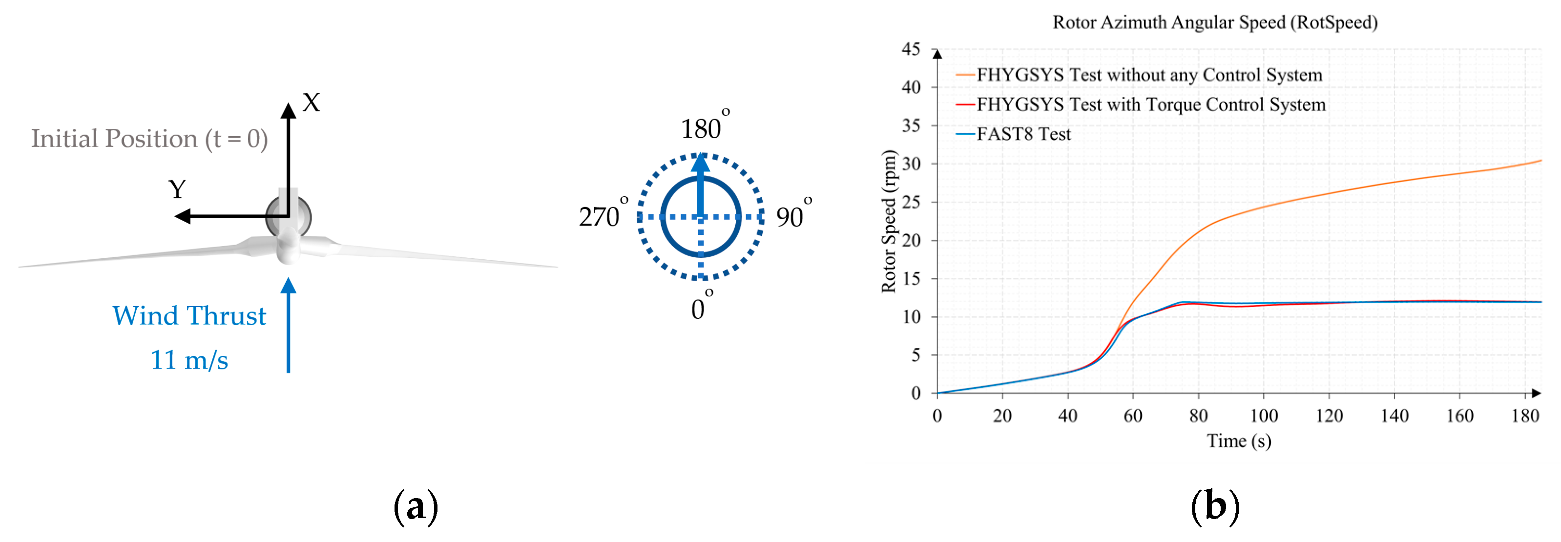
Appendix B.1. Test B1. Wind Speed 11 m/s and Direction 70 Degrees
| Section | Parameter | Original Value | Modified Value |
|---|---|---|---|
| PropagationDir | 0 | −70 | |
| Parameters for steady wind conditions | HWindSpeed | 0 | 11 |
| Section | Parameter | Original Value | Modified Value |
|---|---|---|---|
| Initial conditions | RotSpeed | 11.89 | 0 |
| NacYaw | 0 | 70 |


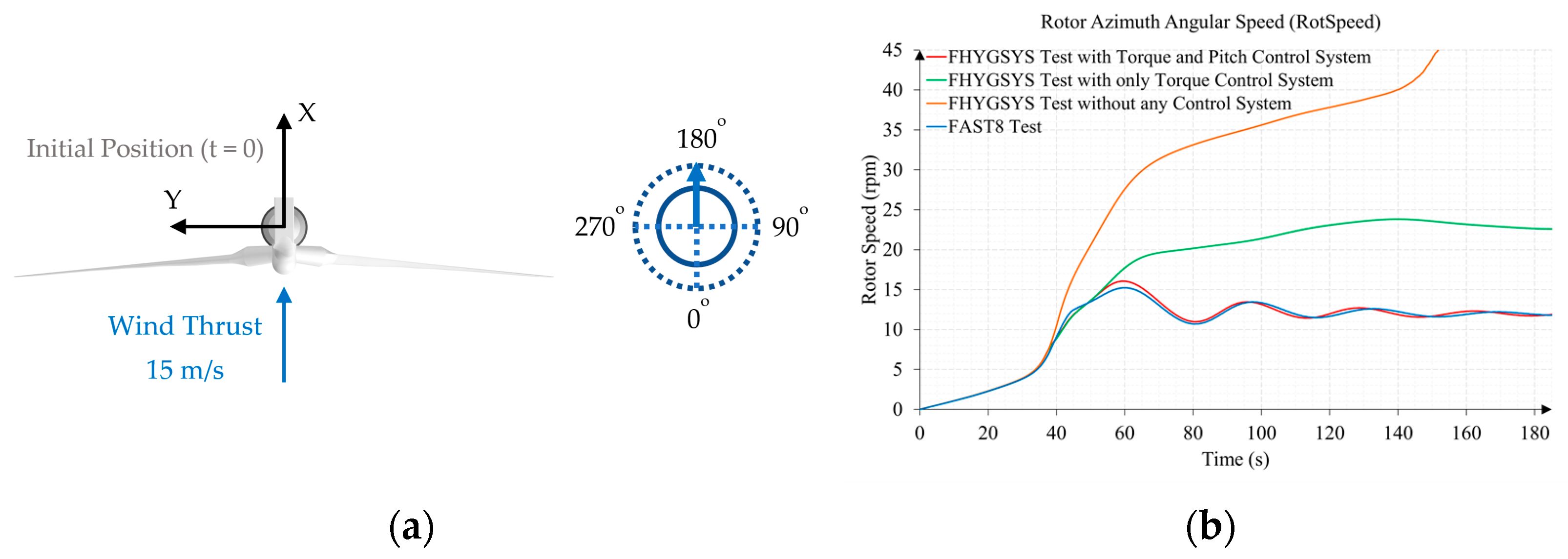
Appendix B.2. Test B2. Wind Speed 15 m/s and Direction 0 Degrees
| Section | Parameter | Original Value | Modified Value |
|---|---|---|---|
| PropagationDir | 0 | 0 | |
| Parameters for steady wind conditions | HWindSpeed | 0 | 15 |
| Section | Parameter | Original Value | Modified Value |
|---|---|---|---|
| Initial conditions | RotSpeed | 12.1 | 0 |
| NacYaw | 0 | 0 |


References
- Çengel, Y.A.; Cimbala, J.M. Fluid Mechanics: Fundamentals and Applications, 1st ed.; McGraw-Hill: New York, NY, USA, 2006. [Google Scholar]
- Hansen, M.O.L. Aerodynamics of Wind Turbines, 1st ed.; James & James Science Publishers, Ltd.: London, UK, 2000. [Google Scholar]
- Jonkman, J.M. Modeling of the UAE Wind Turbine for Refinement of FAST_AD.; NREL/TP-500-34755; NREL: Golden, CO, USA, 2003. [Google Scholar] [CrossRef]
- Burton, T.; Sharpe, D.; Jenkins, N.; Bossanyi, E. Wind Energy Handbook, 1st ed.; John Wiley & Sons, Ltd.: Chichester, UK, 2001. [Google Scholar]
- FAST v8. 2016. Available online: https://www.nrel.gov/wind/nwtc/fastv8.html (accessed on 13 May 2023).
- HAWC2. 2007. Available online: https://www.hawc2.dk (accessed on 13 May 2023).
- Cordle, A.; Jonkman, J. State of the Art in Floating Wind Turbine Design Tools. In Proceedings of the 21st International Offshore and Polar Engineering Conference, Maui, HI, USA, 19–24 June 2011. Available online: https://www.nrel.gov/docs/fy12osti/50543.pdf (accessed on 15 May 2023).
- Jonkman, J.; Larsen, T.; Hansen, A.; Nygaard, T.; Maus, K.; Karimirad, M.; Gao, Z.; Moan, T.; Fylling, I.; Nichols, J.; et al. Offshore Code Comparison Collaboration within IEA Wind Task 23: Phase IV Results Regarding Floating Wind Turbine Modelling. In Proceedings of the European Wind Energy Conference (EWEC), Warsaw, Poland, 20–23 April 2010. [Google Scholar] [CrossRef]
- Jonkman, J.; Robertson, A.; Popko, W.; Vorpahl, F.; Zuga, A.; Kohlmeier, M.; Larsen, T.J.; Yde, A.; Saetertro, K.; Okstad, K.M.; et al. Offshore Code Comparison Collaboration Continuation (OC4), Phase I—Results of Coupled Simulations of an Offshore Wind Turbine with Jacket Support Structure: Preprint; NREL/CP-5000-54124; NREL: Golden, CO, USA, 2012; Available online: https://www.nrel.gov/docs/fy12osti/54124.pdf (accessed on 15 May 2023).
- Robertson, A.N.; Wendt, F.; Jonkman, J.M.; Popko, W.; Dagher, H.; Gueydon, S.; Qvist, J.; Vittori, F.; Azcona, J.; Uzunoglu, E.; et al. OC5 Project Phase II: Validation of Global Loads of the DeepCwind Floating Semisubmersible Wind Turbine. Energy Proc. 2017, 137, 38–57. [Google Scholar] [CrossRef]
- Bergua, R.; Robertson, A.; Jonkman, J.; Branlard, E.; Fontanella, A.; Belloli, M.; Schito, P.; Zasso, A.; Persico, G.; Sanvito, A.; et al. OC6 Project Phase III: Validation of the Aerodynamic Loading on a Wind Turbine Rotor Undergoing Large Motion Caused by a Floating Support Structure. Wind Energy Sci. 2023, 8, 465–485. [Google Scholar] [CrossRef]
- Zhao, D.; Han, N.; Goh, E.; Cater, J.; Reinecke, A. Chapter 7—Aerodynamics of horizontal axis wind turbines and wind farms. In Wind Turbines and Aerodynamics Energy Harvesters, 1st ed.; Zhao, D., Han, N., Goh, E., Cater, J., Reinecke, A., Eds.; Academic Press: London, UK, 2019; pp. 431–461. [Google Scholar] [CrossRef]
- Song, W.; Sun, C.; Zuo, Y.; Jahangiri, V.; Lu, Y.; Han, Q. Conceptual Study of a Real-Time Hybrid Simulation Framework for Monopile Offshore Wind Turbines Under Wind and Wave Loads. Front. Built. Environ. 2020, 6, 129. [Google Scholar] [CrossRef]
- Jonkman, J.; Butterfield, S.; Musial, W.; Scott, G. Definition of a 5-MW Reference Wind Turbine for Offshore System Development; NREL/TP-500-38060; NREL: Golden, CO, USA, 2009. [Google Scholar] [CrossRef]
- Mendoza, N.; Robertson, A.; Wright, A.; Jonkman, J.; Wang, L.; Bergua, R.; Ngo, T.; Das, T.; Odeh, M.; Mohsin, K.; et al. Verification and Validation of Model-Scale Turbine Performance and Control Strategies for the IEA Wind 15 MW Reference Wind Turbine. Energies 2022, 15, 7649. [Google Scholar] [CrossRef]
- Abdelkhalig, A.; Elgendi, M.; Selim, M.Y.E. Review on validation techniques of blade element momentum method implemented in wind turbines. IOP Conf. Ser. Earth Environ. Sci. 2022, 1074, 012008. [Google Scholar] [CrossRef]
- Bangga, G. Wind Turbine Aerodynamics Modeling Using CFD Approaches, 1st ed.; AIP Publishing: Melville, NY, USA, 2022. [Google Scholar] [CrossRef]
- Khan, S. A Modeling Study Focused on Improving the Aerodynamic Performance of a Small Horizontal Axis Wind Turbine. Sustainability 2023, 15, 5506. [Google Scholar] [CrossRef]
- Kara, F. Coupled dynamic analysis of horizontal axis floating offshore wind turbines with a spar buoy floater. Wind Eng. 2023, 47, 607–625. [Google Scholar] [CrossRef]
- Jonkman, J. Definition of the Floating System for Phase IV of OC3; NREL/TP-500-47535; NREL: Golden, CO, USA, 2010. [Google Scholar] [CrossRef]
- Jonkman, J.; Musial, W. Offshore Code Comparison Collaboration (OC3) for IEA Task 23 Offshore Wind Technology and Deployment; NREL/TP-5000-48191; NREL: Golden, CO, USA, 2010. [Google Scholar] [CrossRef]
- Shaler, K.; Anderson, B.; Martínez-Tossas, L.A.; Branlard, E.; Johnson, N. Comparison of free vortex wake and blade element momentum results against large-eddy simulation results for highly flexible turbines under challenging inflow conditions. Wind Energy Sci. 2023, 8, 383–399. [Google Scholar] [CrossRef]
- OpenFAST. 2017. Available online: https://www.nrel.gov/wind/nwtc/openfast.html (accessed on 25 May 2023).
- Benelghali, S.; Balme, R.; Le Saux, K.; Benbouzid, M.; Charpentier, J.F.; Hauville, F. A Simulation Model for the Evaluation of the Electrical Power Potential Harnessed by a Marine Current Turbine. IEEE J. Ocean. Eng. 2007, 32, 786–797. [Google Scholar] [CrossRef]
- Batten, W.M.J.; Bahaj, A.S.; Molland, A.F.; Chaplin, J.R. Experimentally validated numerical method for the hydrodynamic design of horizontal axis tidal turbines. Ocean Eng. 2006, 34, 1013–1020. [Google Scholar] [CrossRef]
- Bahaj, A.S.; Molland, A.F.; Chaplin, J.R.; Batten, W.M.J. Power and thrust measurements of marine current turbines under various hydrodynamic flow conditions in a cavitation tunnel and a towing tank. Renew. Energy 2006, 32, 407–426. [Google Scholar] [CrossRef]
- Stelzenmuller, N. Marine Hydrokinetic Turbine Array Performance and Wake Characteristics. Master’s Thesis, University of Washington, Seattle, WA, USA, 2013. Available online: http://depts.washington.edu/pmec/docs/20131209_StelzenmullerN_thesis_ArrayOptimization.pdf (accessed on 25 May 2023).
- Chime, A.H. Analysis of Hydrokinetic Turbines in Open Channel Flows. Master’s Thesis, University of Washington, Seattle, WA, USA, 2013. Available online: http://depts.washington.edu/pmec/docs/Chime_Thesis.pdf (accessed on 25 May 2023).
- ANSYS Fluent. 2006. Available online: https://www.ansys.com/products/fluids/ansys-fluent (accessed on 25 May 2023).
- Allsop, S.; Peyrard, C.; Thies, P.R.; Boulougouris, E.; Harrison, G.P. Hydrodynamic analysis of a ducted, open centre tidal stream turbine using blade element momentum theory. Ocean Eng. 2017, 141, 531–542. [Google Scholar] [CrossRef]
- Pucci, M.; Di Garbo, C.; Bellafiore, D.; Zanforlin, S.; Umgiesser, G. A BEM-Based Model of a Horizontal Axis Tidal Turbine in the 3D Shallow Water Code SHYFEM. J. Mar. Sci. Eng. 2022, 10, 1864. [Google Scholar] [CrossRef]
- SHYFEM. 2020. Available online: https://github.com/SHYFEM-model/shyfem (accessed on 25 May 2023).
- Gao, Y.; Liu, H.; Lin, Y.; Gu, Y.; Ni, Y. Hydrodynamic Analysis of Tidal Current Turbine under Water-Sediment Conditions. J. Mar. Sci. Eng. 2022, 10, 515. [Google Scholar] [CrossRef]
- Bir, G.S.; Lawson, M.J.; Li, Y. Structural Design of a Horizontal-Axis Tidal Current Turbine Composite Blade. In Proceedings of the 30th International Conference on Ocean, Offshore, and Arctic Engineering, Rotterdam, The Netherlands, 19–24 June 2011. [Google Scholar] [CrossRef]
- Lawson, M.J.; Li, Y. Development and Verification of a Computational Fluid Dynamics Model of a Horizontal-Axis Tidal Current Turbine. In Proceedings of the 30th International Conference on Ocean, Offshore, and Arctic Engineering, Rotterdam, The Netherlands, 19–24 June 2011. [Google Scholar] [CrossRef]
- Tamarit, F.; García, E.; Quiles, E.; Correcher, A. Model and Simulation of a Floating Hybrid Wind and Current Turbines Integrated Generator System, Part I: Kinematics and Dynamics. J. Mar. Sci. Eng. 2023, 11, 126. [Google Scholar] [CrossRef]
- Tamarit, F.; García, E.; Quiles, E.; Correcher, A. Model and Simulation of a Floating Hybrid Wind and Current Turbines Integrated Generator System, Part II: Hydrodynamics and Acting Forces. J. Mar. Sci. Eng. 2023, 11, 987. [Google Scholar] [CrossRef]
- Newman, J.N. Marine Hydrodynamics; The MIT Press: Cambridge, MA, USA, 1977. [Google Scholar]
- García, E.; Correcher, A.; Quiles, E.; Tamarit, F.; Morant, F. Control and Supervision Requirements for Floating Hybrid Generator Systems. Int. J. Environ. Res. Public Health 2022, 19, 12781. [Google Scholar] [CrossRef] [PubMed]
- Chapra, S.C.; Canale, R.P. Numerical Methods for Engineers: With Software and Programming Applications, 4th ed.; McGraw-Hill: New York, NY, USA, 2001. [Google Scholar]
- IEC 61400–3; Wind Turbines—Part 3: Design Requirements for Offshore Wind Turbines, 1st ed. International Electrotechnical Commission (IEC): Geneva, Switzerland, 2009.
- Smith, R.T.; Minton, R.B. Calculus, Premiere ed.; McGraw-Hill: Boston, MA, USA, 2000. [Google Scholar]
- Moriarty, P.J.; Hansen, A.C. AeroDyn Theory Manual; NREL/TP-500-36881; NREL: Golden, CO, USA, 2005. [Google Scholar] [CrossRef]
- Riley, W.F.; Sturges, L.D. Engineering Mechanics: Statics, 2nd ed.; John Wiley & Sons, Inc.: Hoboken, NJ, USA, 1996. [Google Scholar]
- Soriano, L.A.; Yu, W.; Rubio, J.J. Modeling and Control of Wind Turbine. Math. Probl. Eng. 2013, 2013, 982597. [Google Scholar] [CrossRef]
- Rolán, A.; Luna, A.; Vázquez, G.; Aguilar, D.; Azevedo, G. Modeling of a variable speed wind turbine with a Permanent Magnet Synchronous Generator. In Proceedings of the IEEE International Symposium on Industrial Electronics, Seoul, Republic of Korea, 5–8 July 2009. [Google Scholar] [CrossRef]
- Pham, T.-D.; Dinh, M.-C.; Kim, H.-M.; Nguyen, T.-T. Simplified Floating Wind Turbine for Real-Time Simulation of Large-Scale Floating Offshore Wind Farms. Energies 2021, 14, 4571. [Google Scholar] [CrossRef]
- Tipler, P.; Mosca, G. Physics for Scientists and Engineers, 5th ed.; W.H. Freeman and Company: New York, NY, USA, 2003. [Google Scholar]
- Jonkman, J. Dynamics Modeling and Loads Analysis of an Offshore Floating Wind Turbine; NREL/TP-500-41958; NREL: Golden, CO, USA, 2007. [Google Scholar] [CrossRef]
- Ogata, K. Modern Control Engineering, 5th.ed.; Pearson Prentice Hall: New Jersey, NJ, USA, 2010. [Google Scholar]
- Hansen, M.H.; Hansen, A.D.; Larsen, T.J.; Øye, S.; Sørensen, P.; Fuglsang, P. Control Design for a Pitch-Regulated, Variable Speed Wind Turbine; Technical Report Risoe-R No. 1500; Risoe National Laboratory: Roskilde, Denmark, 2005; Available online: https://backend.orbit.dtu.dk/ws/portalfiles/portal/7710881/ris_r_1500.pdf (accessed on 30 June 2023).
- Robertson, A.; Jonkman, J.; Masciola, M.; Song, H.; Goupee, A.; Coulling, A.; Luan, C. Definition of the Semisubmersible Floating System for Phase II of OC4; NREL/TP-5000-60601; NREL: Golden, CO, USA, 2014. [Google Scholar] [CrossRef]
- Jonkman, J.M.; Robertson, A.N.; Hayman, G.J. HydroDyn User’s Guide and Theory Manual; NREL/TP Draft Paper; NREL: Golden, CO, USA, 2014; Available online: https://www.nrel.gov/wind/nwtc/assets/downloads/HydroDyn/HydroDyn_Manual.pdf (accessed on 30 June 2023).


| Property 1 | Value | Symbol |
|---|---|---|
| Elevation to tower top above still water level | 87.6 m | |
| Elevation to tower base above still water level | 10 m | |
| Tower top diameter | 3.87 m | |
| Tower base diameter | 6.5 m |
| Property 1 | Value | Symbol |
|---|---|---|
| Rated electrical power | 5 MW | |
| Number of blades | 3 | |
| Hub height | 90 m | |
| Hub radius | 1.5 m | |
| Blade length | 61.5 m | |
| Precone | −2.5 deg | |
| Shaft tilt | 5 deg | |
| Rated rotor speed | 12.1 rpm | |
| Gearbox ratio | 97:1 | |
| Electrical generator efficiency | 0.944 | |
| Generator inertia about high-speed shaft | 534.116 kg·m2 | |
| Minimum generator speed to connect the torque controller | 670 rpm | |
| Rated generator torque | 43,093.55 N·m | |
| Maximum generator torque rate | 15,000 N·m/s | |
| Minimum blade-pitch setting | 0 deg | |
| Maximum blade-pitch setting | 90 deg | |
| Maximum absolute blade pitch rate | 8 deg/s |
| Node | rni (m) | dpni (m) | φTwist (deg) | LChord (m) | Airfoil |
|---|---|---|---|---|---|
| 1 | 2.8667 | 2.7333 | 0 2 | 3.542 | Cylinder 1 |
| 2 | 5.6 | 2.7333 | 0 2 | 3.854 | Cylinder 1 |
| 3 | 8.3333 | 2.7333 | 0 2 | 4.167 | Cylinder 2 |
| 4 | 11.75 | 4.1 | 13.308 | 4.557 | DU 40 |
| 5 | 15.85 | 4.1 | 11.48 | 4.652 | DU 35 |
| 6 | 19.95 | 4.1 | 10.162 | 4.458 | DU 35 |
| 7 | 24.05 | 4.1 | 9.011 | 4.249 | DU 30 |
| 8 | 28.15 | 4.1 | 7.795 | 4.007 | DU 25 |
| 9 | 32.25 | 4.1 | 6.544 | 3.748 | DU 25 |
| 10 | 36.35 | 4.1 | 5.361 | 3.502 | DU 21 |
| 11 | 40.45 | 4.1 | 4.188 | 3.256 | DU 21 |
| 12 | 44.55 | 4.1 | 3.125 | 3.01 | NACA 64–618 |
| 13 | 48.65 | 4.1 | 2.319 | 2.764 | NACA 64–618 |
| 14 | 52.75 | 4.1 | 1.526 | 2.518 | NACA 64–618 |
| 15 | 56.1667 | 2.7333 | 0.863 | 2.313 | NACA 64–618 |
| 16 | 58.9 | 2.7333 | 0.37 | 2.086 | NACA 64–618 |
| 17 | 61.6333 | 2.7333 | 0.106 | 1.419 | NACA 64–618 |
| Wind Speed 1 | Wind Turbine Speed 2 | Proportional Gain | Integration Time |
|---|---|---|---|
| 3 | 6.97 | 0.09 | 15 |
| 4 | 7.18 | 0.08 | 15 |
| 5 | 7.51 | 0.07 | 15 |
| 6 | 7.94 | 0.06 | 15 |
| 7 | 8.47 | 0.05 | 20 |
| 8 | 9.16 | 0.04 | 30 |
| 9 | 10.3 | 0.03 | 40 |
| 10 | 11.43 | 0.02 | 50 |
| 11 | 11.89 | 0.018 | 100 |
| 11. 4 | 12.1 | 0.019 | 100 |
| 12 | 12.1 | 0.018 | 100 |
| 13 to 25 | 12.1 | 0.01 | 200 |
| 1 | 0 |
| 0 |
| Wind Speed 1 | Wind Turbine Speed 2 | Proportional Gain | Integration Time | Trigger Offset Factor FTrigg(%) (%) |
|---|---|---|---|---|
| 3 to 11 | 6.97 to 11.89 | 0 | 1 | 0 |
| 11.4 | 12.1 | 0.0023 | 7 | 11 |
| 12 | 12.1 | 0.0025 | 7 | 11 |
| 13 | 12.1 | 0.0016 | 7 | 7 |
| 14 | 12.1 | 0.0013 | 7 | 4.5 |
| 15 | 12.1 | 0.0012 | 7 | 3 |
| 16 | 12.1 | 0.0011 | 7 | 3 |
| 17 | 12.1 | 0.0011 | 7 | 3 |
| 18 | 12.1 | 0.0011 | 7 | 3 |
| 19 | 12.1 | 0.0010 | 7 | 3 |
| 20 | 12.1 | 0.0010 | 7 | 3 |
| 21 | 12.1 | 0.0010 | 7 | 3 |
| 22 | 12.1 | 0.0010 | 7 | 3 |
| 23 | 12.1 | 0.0010 | 7 | 3 |
| 24 | 12.1 | 0.0010 | 7 | 3 |
| 25 | 12.1 | 0.0010 | 7 | 3 |
| −1 | |
| 0 |
| Property | Value | Symbol |
|---|---|---|
| Length from the hub center to tube junction | 4.427 m | |
| Length from the hub center to floating platform | 12.09 m | |
| Maximum Length between the center of the main tube and the others | 2 m | |
| Turbine support tube diameter | 0.6 m |
| Description | Value (m) | Symbol |
|---|---|---|
| Origin of clockwise turbine coordinate system | (0, 17.1, −20) | poC−MCT (BODY) |
| Origin of counterclockwise turbine coordinate system | (0, −17.1, −20) | poCC−MCT (BODY) |
| Property | Value | Symbol |
|---|---|---|
| Rated electrical power 1 | 550 kW | |
| Number of blades 1 | 2 | |
| Hub depth 1 | −20 m | |
| Hub radius 1 | 1 m | |
| Blade length 1 | 9 m | |
| Precone 1 | 0 deg | |
| Shaft tilt 1 | 0 deg | |
| Rated rotor speed 1 | 11.5 rpm | |
| Gearbox ratio 2 | 97:1 | |
| Electrical generator efficiency 2 | 0.944 | |
| Generator inertia about high-speed shaft 2 | 534.116 kg·m2 | |
| Minimum generator speed to connect the torque controller 3 | 325 rpm | |
| Rated generator torque 3 | 4971.531 N·m | |
| Maximum generator torque rate 3 | 1000 N·m/s | |
| Minimum blade-pitch setting 2 | 0 deg | |
| Maximum blade-pitch setting 2 | 90 deg | |
| Maximum absolute blade pitch rate 3 | 4 deg/s |
| Node1 | pni (m) | dpni (m) | ϕTwist (deg) | LChord (m) | Hydrofoil |
|---|---|---|---|---|---|
| 1 | 1.075 | 0.15 | 0 2 | 0.8 | Cylinder 3 |
| 2 | 1.3607 | 0.42143 | 12.86 | 0.87812 | NACA 63–424 |
| 3 | 1.7821 | 0.42143 | 12.86 | 1.1802 | NACA 63–424 |
| 4 | 2.2036 | 0.42143 | 12.86 | 1.5287 | NACA 63–424 |
| 5 | 2.625 | 0.42143 | 12.805 | 1.7023 | NACA 63–424 |
| 6 | 3.1342 | 0.59702 | 10.727 | 1.6304 | NACA 63–424 |
| 7 | 3.7313 | 0.59702 | 8.8252 | 1.5404 | NACA 63–424 |
| 8 | 4.3283 | 0.59702 | 7.5219 | 1.4565 | NACA 63–424 |
| 9 | 4.9253 | 0.59702 | 6.5262 | 1.372 | NACA 63–424 |
| 10 | 5.5223 | 0.59702 | 5.7432 | 1.2867 | NACA 63–424 |
| 11 | 6.1193 | 0.59702 | 5.1057 | 1.2002 | NACA 63–424 |
| 12 | 6.7164 | 0.59702 | 4.5608 | 1.1116 | NACA 63–424 |
| 13 | 7.3134 | 0.59702 | 4.0772 | 1.0214 | NACA 63–424 |
| 14 | 7.9104 | 0.59702 | 3.6195 | 0.9299 | NACA 63–424 |
| 15 | 8.5074 | 0.59702 | 3.1795 | 0.83481 | NACA 63–424 |
| 16 | 9.1045 | 0.59702 | 2.7241 | 0.73776 | NACA 63–424 |
| 17 | 9.7015 | 0.59702 | 2.2413 | 0.63825 | NACA 63–424 |
| Current Speed 1 | MCT Speed 2 | Proportional Gain | Integration Time |
|---|---|---|---|
| 0.5 | 3.37 | 0.300 | 30 |
| 0.65 | 4.363 | 0.150 | 30 |
| 0.8 | 5.356 | 0.100 | 30 |
| 0.95 | 6.349 | 0.090 | 30 |
| 1.1 | 7.35 | 0.080 | 30 |
| 1.25 | 8.355 | 0.070 | 40 |
| 1.4 | 9.36 | 0.060 | 50 |
| 1.55 | 10.21 | 0.050 | 60 |
| 1.7 | 10.77 | 0.045 | 70 |
| 1.85 | 11.32 | 0.045 | 80 |
| 2.0 | 11.47 | 0.040 | 80 |
| 2.03 | 11.5 | 0.040 | 150 |
| 2.1 to 3.0 | 11.5 | 0.030 | 150 |
| Current Speed 1 | MCT Speed 2 | Proportional Gain | Integration Time | Trigger Offset Factor FTrigg(%) (%) |
|---|---|---|---|---|
| 0.5 to 2.0 | 3.37 to 11.47 | 0 | 1 | 0 |
| 2.03 | 11.5 | 0.0015 | 9 | 12 |
| 2.1 | 11.5 | 0.0012 | 10 | 10 |
| 2.25 | 11.5 | 0.0012 | 10 | 10 |
| 2.4 | 11.5 | 0.0012 | 10 | 10 |
| 2.55 | 11.5 | 0.0012 | 10 | 10 |
| 2.7 | 11.5 | 0.0012 | 10 | 10 |
| 2.85 | 11.5 | 0.0012 | 10 | 10 |
| 3 | 11.5 | 0.0012 | 10 | 10 |
Disclaimer/Publisher’s Note: The statements, opinions and data contained in all publications are solely those of the individual author(s) and contributor(s) and not of MDPI and/or the editor(s). MDPI and/or the editor(s) disclaim responsibility for any injury to people or property resulting from any ideas, methods, instructions or products referred to in the content. |
© 2023 by the authors. Licensee MDPI, Basel, Switzerland. This article is an open access article distributed under the terms and conditions of the Creative Commons Attribution (CC BY) license (https://creativecommons.org/licenses/by/4.0/).
Share and Cite
Tamarit, F.; García, E.; Quiles, E.; Correcher, A. BEM Turbine Model and PID Control System of a Floating Hybrid Wind and Current Turbines Integrated Generator System. J. Mar. Sci. Eng. 2023, 11, 1634. https://doi.org/10.3390/jmse11081634
Tamarit F, García E, Quiles E, Correcher A. BEM Turbine Model and PID Control System of a Floating Hybrid Wind and Current Turbines Integrated Generator System. Journal of Marine Science and Engineering. 2023; 11(8):1634. https://doi.org/10.3390/jmse11081634
Chicago/Turabian StyleTamarit, Fernando, Emilio García, Eduardo Quiles, and Antonio Correcher. 2023. "BEM Turbine Model and PID Control System of a Floating Hybrid Wind and Current Turbines Integrated Generator System" Journal of Marine Science and Engineering 11, no. 8: 1634. https://doi.org/10.3390/jmse11081634
APA StyleTamarit, F., García, E., Quiles, E., & Correcher, A. (2023). BEM Turbine Model and PID Control System of a Floating Hybrid Wind and Current Turbines Integrated Generator System. Journal of Marine Science and Engineering, 11(8), 1634. https://doi.org/10.3390/jmse11081634