Article

Experimental and Numerical Study on Crack Propagation of Cracked Plates under Low Cycle Fatigue Loads

1
Key Laboratory of High Performance Ship Technology, Wuhan University of Technology, Ministry of Education, Wuhan 430063, China
2
School of Civil Engineering and Architecture, Wuhan Polytechnic University, Wuhan 430048, China
3
School of Naval Architecture and Navigation, Wuhan Technical College of Communications, Wuhan 430065, China
4
Marine Equipment and Technology Institute, Jiangsu University of Science and Technology, Zhenjiang 212000, China
*
Author to whom correspondence should be addressed.
J. Mar. Sci. Eng. 2023, 11(7), 1436; https://doi.org/10.3390/jmse11071436
Submission received: 29 June 2023 / Revised: 13 July 2023 / Accepted: 14 July 2023 / Published: 18 July 2023
(This article belongs to the Special Issue Advanced Analysis of Marine Structures)

Abstract

:
The traditional study on fatigue strength for ship structures usually focuses on high cycle fatigue and ignores low cycle fatigue. However, given the recent trend towards large-scale ship development, the stress and deformation experienced by ship structures are becoming increasingly significant, leading to greater attention being paid to low cycle fatigue damage. Therefore, experimental and numerical studies on crack propagation behavior of cracked plates under low cycle fatigue loads were carried out in this paper, in order to explain the fatigue crack propagation mechanism. The effect of the stress ratio and maximum applied load on the crack propagation behavior was investigated by conducting experimental research on the cracked plate of AH32 steel. The experimental results show that an increasing maximum applied load and decreasing stress ratio will shorten the fatigue life of the cracked plate. Meanwhile, based on the finite element method, the distribution of the stress–strain field at the crack tip and the effect of crack closure were evaluated. The influencing factors such as the stress ratio and crack length were considered in numerical studies, which provided a new way to study the low cycle fatigue crack propagation behavior.

1. Introduction

Our foreign trade has flourished in recent years, and its dependence on the marine environment and resources has increased substantially. Developing the marine economy and building “maritime power” has become an inevitable choice for our economy to reach a new level. The trend of large-scale development of ships is inevitable. However, given the recent trend towards large-scale ship development, the stress and deformation experienced by ship structures are becoming increasingly significant, leading to greater attention being paid to low cycle fatigue damage.
The origins of the low cycle fatigue problem date back to the 1960s, when Manson and Coffin [1] established the low cycle fatigue theory, respectively. Their research indicated that plastic deformation of materials under high-stress amplitude loading was the primary cause of fatigue damage in structures. As further research was conducted in this area, both domestic and international scholars began to recognize the significance of low cycle fatigue on ship structures [2,3,4,5,6,7,8]. In 1965, Dunham [2] conducted fatigue tests on large submarine structures with full-scale models, observing crack propagation behavior under low cycle fatigue loading. Later, Jordan and Cochran [3,4] investigated the fatigue damage phenomenon of 86 ships in operation, finding that structural fatigue damage was a crucial factor leading to the failure of ships. Munse [5] summarized the findings of Jordan’s research, developing S-N fatigue curves for locations prone to fatigue damage and proposing a fatigue strength assessment applicable to different hull components. Radek [6] conducted low cycle fatigue tests using miniature test samples, which demonstrated that cyclic parameters produced consistent results regardless of the varying sample volumes.
In the 1980s, researchers in domestic academia began to focus on studying the problem of low cycle fatigue in ship structures. In 1991, Chen [9] conducted tests on large submarine structures using scale models and employed similar theoretical approaches to analyze the results. Building on Urm’s [10] work on low cycle fatigue in oil tankers, Cui [11] investigated the causes of low cycle fatigue damage in ship structures and developed a nonlinear model for calculating accumulative fatigue damage to predict their low cycle fatigue life. In 2008, Liu [12] carried out experiments on 921A steel plates to study the behavior of crack propagation in damaged ship structures under cyclic tensile loading, which served as a foundation for subsequent predictions of low cycle fatigue in ship structures.
The cracked plate will gradually propagate under cyclic loading, and the stress and strain field near the crack tip will change accordingly. The fracture parameters, such as the stress intensity factor K [13,14,15,16,17,18,19], crack tip opening displacement (CTOD) [20,21], the J-integral [22], the size of the reversed plastic zone [23,24,25], etc., are important factors to assess the fatigue crack propagation life. Fatigue crack propagation research has been primarily conducted by scholars from the perspective of the crack tip stress distribution [26,27] and crack closure effect [28,29,30], etc., leading to several valuable conclusions [31,32,33,34,35,36,37,38,39,40]. When a severe stress concentration occurs, plastic deformation arises in the surrounding area, which gradually accumulates, eventually resulting in crack propagation. As the crack tip passes through the plastic zone, a plastic trailing zone forms at the original crack tip, creating a significant residual compressive stress at the crack tip. This residual compressive stress causes crack closure, which affects the stress–strain field distribution near the crack tip, ultimately reducing the effective stress intensity factor range and the crack growth rate. Therefore, the paper will carry out experimental and numerical studies on the crack propagation behavior of cracked plates under low cycle fatigue loads, in order to explain the fatigue crack propagation mechanism. The effect of the stress ratio and maximum applied load on the crack propagation behavior was investigated by conducting experimental research on a cracked plate of AH32 steel. Meanwhile, based on the finite element method, the distribution of the stress–strain field at the crack tip and the effect of crack closure were evaluated. The influencing factors such as the stress ratio and crack length were considered in numerical studies, which provided a new way to study the low cycle fatigue crack propagation behavior.

2. Experimental Investigations on the Crack Growth Behavior of Cracked Plates under Low Cycle Fatigue Loads

2.1. Experimental Setup

The experiments on low cycle fatigue crack growth were conducted on a 3 mm thick steel plate with a central crack, and the standard used for the tests is ASTNE 647-05 [41]. The dimensions of the plate and crack are shown in Figure 1, where the initial crack length is a0 = 16 mm. The material used for the tests was AH32 steel, which is a high-strength steel commonly used in the manufacturing of hull and deck components for ocean-going, coastal, and inland waterway shipping vessels. The basic mechanical properties of the material are listed in Table 1. The chemical composition of the material is as follows (in weight percentage): Carbon (C) 0.18%, Aluminum (Al) 0.02%, Silicon (Si) 0.32%, Manganese (Mn) 1.4%, Phosphorus (P) 0.04%, Sulfur (S) 0.04%, and Niobium (Nb) 0.02%.
The experiments were conducted at room temperature of approximately 20–25 °C and in the air. A computer-controlled servo-hydraulic test machine MTS322 (±250 kN) was used in the testing process, as shown in Figure 2. Each specimen was subjected to load control at a frequency of 1 Hz using a sine wave, with a maximum applied load of 95 kN and stress ratios of 0, 0.1, and 0.2, respectively. The applied cyclic loads used in the present experiment are categorized as low cycle fatigue loads due to the fact that the fatigue lives of smooth specimens subjected to the same cyclic loads are shorter than 10,000 cycles. The crack length was determined by a metallographic microscope connected to a video travelling microscope, while an electronic extensometer was installed on both sides of the crack surface to measure the crack opening displacement (COD). The test procedure for evaluating the behavior of a cracked plate can be divided into three distinct steps. Firstly, the area around the crack is carefully sanded to ensure a smooth surface, and strain gauges are affixed to collect data on the crack tip strain value. After the preparation work, the cracked plate is fixed to the MTS by bolts. Then, a single loading is required before cyclic loading to remove the initial deformation of the cracked plate. Finally, the loading equipment program is adjusted, and cyclic loading is performed while collecting data on COD using an extensometer and observing the crack growth process using a metallographic microscope. The MTS is set up with displacement protection to prevent excessive displacement caused by fracture failure of the cracked plate to prevent damage to the machine. The loading conditions and experimental results of AH32 steel are summarized in Table 2.

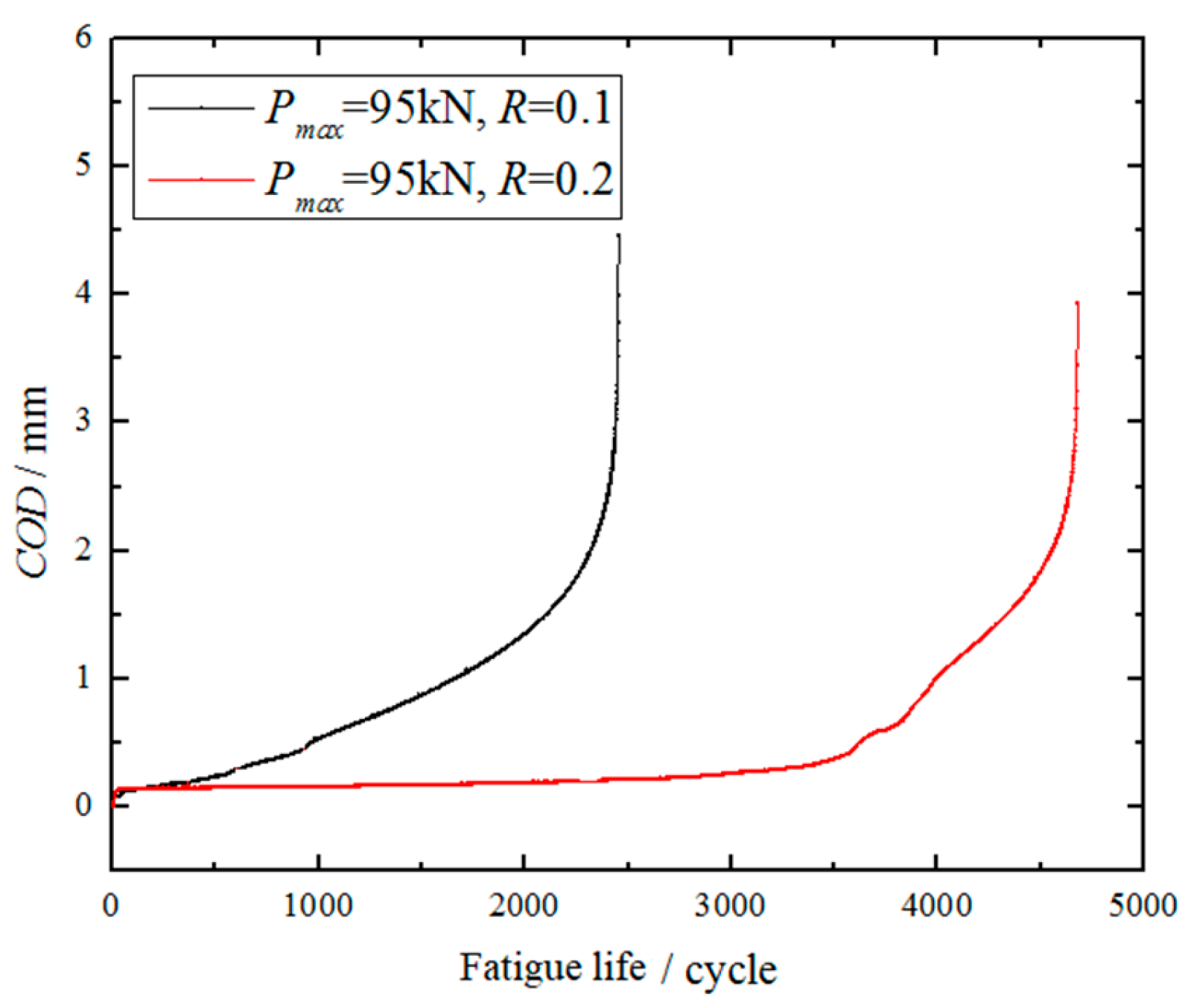
2.2. Experimental Result and Discussion

In order to study the impact of the maximum applied load and stress ratio on fatigue crack growth behavior in cracked plates, a series of low cycle fatigue tests were performed. As depicted in Figure 3, the results indicate that an increase in the maximum applied load at a constant stress ratio leads to an increase in crack growth rate, resulting in shorter fatigue life. Conversely, when the maximum applied load remains constant, an increase in the stress ratio leads to a decrease in the crack growth rate, thereby prolonging the material’s fatigue life. Figure 4 illustrates how crack opening displacement (COD) varies under different stress ratios, revealing that the effect of various loads on COD differs. Specifically, as the stress ratio increases, the value of COD does not change significantly during the early stages, displaying an approximately linear relationship. However, once the crack has propagated to a certain extent, the COD value begins to increase significantly until the plate fractures. Notably, the change in COD value accurately represents the crack growth rate.

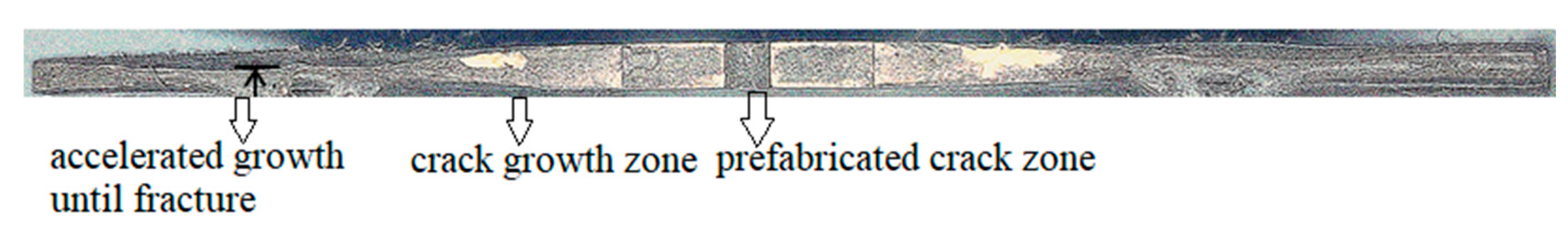
2.3. Observation of Fracture Morphology

In Figure 5, the fracture morphology of an AH32 steel specimen examined during a fatigue test with a stress ratio R = 0.1 is presented. The prefabricated crack area has a relatively smooth surface because it was produced using wire-cut EDM. It is noticeable that there is a significant accumulation of plastic deformation near the crack tip region, and the crack growth zone exhibits plastic slip, which is relatively smoother than the accelerated growth zone. This phenomenon occurs due to the continuous stretching and extrusion of the upper and lower surfaces of the crack during its growth process. As the crack enters the accelerated growth zone, it primarily stretches instead of being extruded, resulting in a comparatively rough section in this part. This section is similar to the fracture surface observed in cases of static load damage.

3. Numerical Analysis and Discussion

This paragraph describes a finite element (FE) analysis performed on a central cracked plate under constant amplitude loading. To simulate high stress and strain gradients near the crack tip more accurately, a singular element is adopted at the crack tip and a refined mesh is used in the region around the crack, as shown in Figure 6. A 1/4 model is considered due to symmetry with dimensions of length L = 100 mm, width w = 50 mm, and initial crack length a0 = 8 mm. Four-node plane-stress elements with full integration (CPS4) are used in the FE mesh model. To simulate crack growth behavior better, a dynamic crack growth approach is employed. This involves periodic release nodes, which allow the crack to propagate gradually. Contacts and constraints are used to simulate the boundary conditions. Specifically, contacts are arranged on both the upper and lower crack surfaces and a rigid line is set at the partition interface to prevent the upper and lower surfaces from crossing each other. The master surface refers to the rigid line, while the slave surface pertains to the crack surface. Since there is no inclination for sliding to occur between the contact surfaces, a friction coefficient of zero has been assigned. The process begins with the bonding of nodes located on the contact surface, followed by the gradual release of these nodes through low cycle fatigue loads to grow the crack. In this finite element analysis, appropriate boundary conditions have been implemented by setting X-symmetric constraints on the Y-axis and Y-symmetric constraints on the X-axis to account for symmetry. The Chaboche kinematic hardening model has been utilized to accurately capture the elastic-plastic stress–strain behavior of the component with a crack. This model is particularly suitable for materials exhibiting Masing-type behavior. The cyclic plasticity model parameters have been optimized based on fatigue experimental data from AH-32 steel and are presented in Table 3.
To balance between accuracy and computational time, it is necessary to select an appropriate refined mesh size. In this study, three mesh sizes of 0.1 × 0.1 mm, 0.05 × 0.05 mm, and 0.02 × 0.02 mm were used to simulate fatigue crack propagation under a constant amplitude cyclic load with a maximum load of Pmax = 95 kN and a stress ratio of R = 0.1. As can be seen from Table 4, there types of mesh were considered to calculate the crack closure parameter U, and the difference between the three mesh sizes was relatively small. While the 0.1 × 0.1 mm mesh may provide an overall assessment of a good economy, it falls short in accurately simulating the stress distribution at the crack tip. To address this limitation, a refined mesh of 0.05 × 0.05 mm is employed in the FE model. This refined mesh offers the dual advantage of efficient computation time and accurate simulation of stress distribution.
To validate the rationality of the numerical model, a finite element analysis was performed with a stress ratio of 0.1. The obtained stress–strain curve from the analysis was then compared with the experimental stress–strain curve, as shown in Figure 7. From Figure 7, it can be observed that the experimental and numerical stress–strain curves are in good agreement, indicating that the chosen material parameters in the FE model accurately reflect the stress–strain behavior of the material and the rationality of the numerical model.

3.1. Analysis of Crack Opening Displacement

The opening and closing of crack opening displacement (COD) can better reflect the change in the crack surface during the crack propagation process. Figure 8 shows the variation of COD under different stress ratios and a maximum applied load of 95 kN. It is evident that the crack is closed at the minimum applied load, with increasing stress ratios leading to larger closure effects. This implies that higher stress ratios tend to bring the crack surfaces closer together, thereby hindering crack propagation. Furthermore, the COD is reduced at the maximum applied load with an increasing stress ratio, primarily due to a decrease in effective driving stress. As the stress ratio increases, the proportion of the applied load that contributes to driving the crack further decreases. Consequently, the crack growth rates are reduced due to the reduced driving force. This finding indicates that higher stress ratios exacerbate the crack closure phenomenon, resulting in reduced crack growth rates, and ultimately causing a retardation effect.

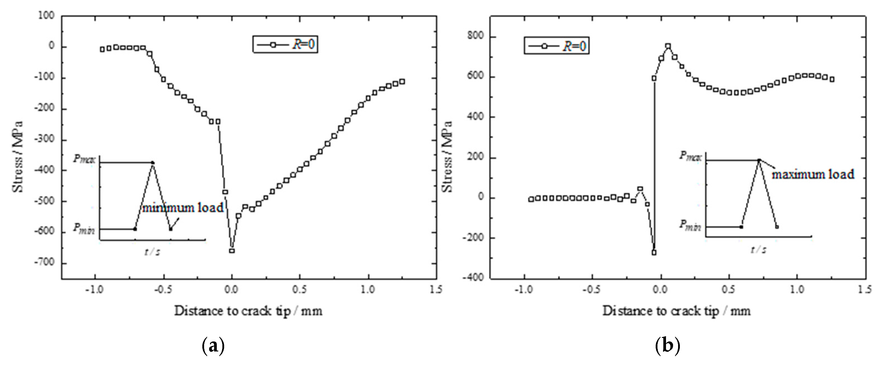
3.2. Analysis of Crack Tip Stress Field

The loading and unloading of cyclic loads can cause changes in the stress field at the crack tip, leading to crack closure and propagation behavior. Figure 9 illustrates the distribution of the normal stress, σ y y , at the crack tip in the y = 0 plane at maximum and minimum applied loads, respectively. It is evident from Figure 9 that plastic deformation occurs behind the crack tip as the load gradually decreases to the minimum applied load, resulting in a compressive stress field that partially closes the crack. As the crack length increases, the residual compressive stress at the crack tip remains almost constant. However, the stress concentration at the crack tip can cause the material to enter a reverse yielding state. Upon loading to the maximum applied load, the crack opens and enters the forward-yielding state, resulting in tensile plastic strain. This analysis indicates that during cyclic loading and unloading, the crack tip experiences reciprocal action between forward and reverse yielding states, leading to the gradual accumulation of plastic strain and prompting crack propagation.

3.3. Analysis of Crack Closure Parameter

The load ratio parameter U , which is commonly employed to characterize the development of crack closure during fatigue crack propagation, can be expressed as:
U = K max K o p K max K min
where K max is the maximum intensity factor, K min is the minimum intensity factor, and K o p is the intensity factor with respect to the crack opening load. The load parameter takes values between 0, which indicates complete crack closure, and 1, which corresponds to the fully open crack condition.
Figure 10 illustrates the load ratio parameter U for different stress ratios, with a comparison between the numerical simulation and test results, where the solid lines represent the FE results and the solid circles represent the test results. The results show that as the stress ratio increases, the load ratio parameter also increases while the crack closure effect weakens. This is because larger stress ratios increase the minimum stress level, which offsets some of the residual compressive stress at the crack tip that promotes crack closure. Consequently, the crack closure effect diminishes. While Figure 10 shows noticeable differences between the experimental and numerical results, the latter demonstrates a more prominent crack closure effect. The average errors in the load ratio parameter for increasing stress ratios are 3.6%, 3.9%, 4.1%, and 4.4%, respectively. Possible reasons for these errors include the idealized numerical simulation of the crack without accounting for blunting at the crack tip, which affects the level of crack closure. Additionally, the extensometer’s relatively large distance from the crack tip in the experiment may have resulted in small measured results due to its insensitivity. Lastly, processing procedures and the initial defects of the specimen could also contribute to measurement errors.

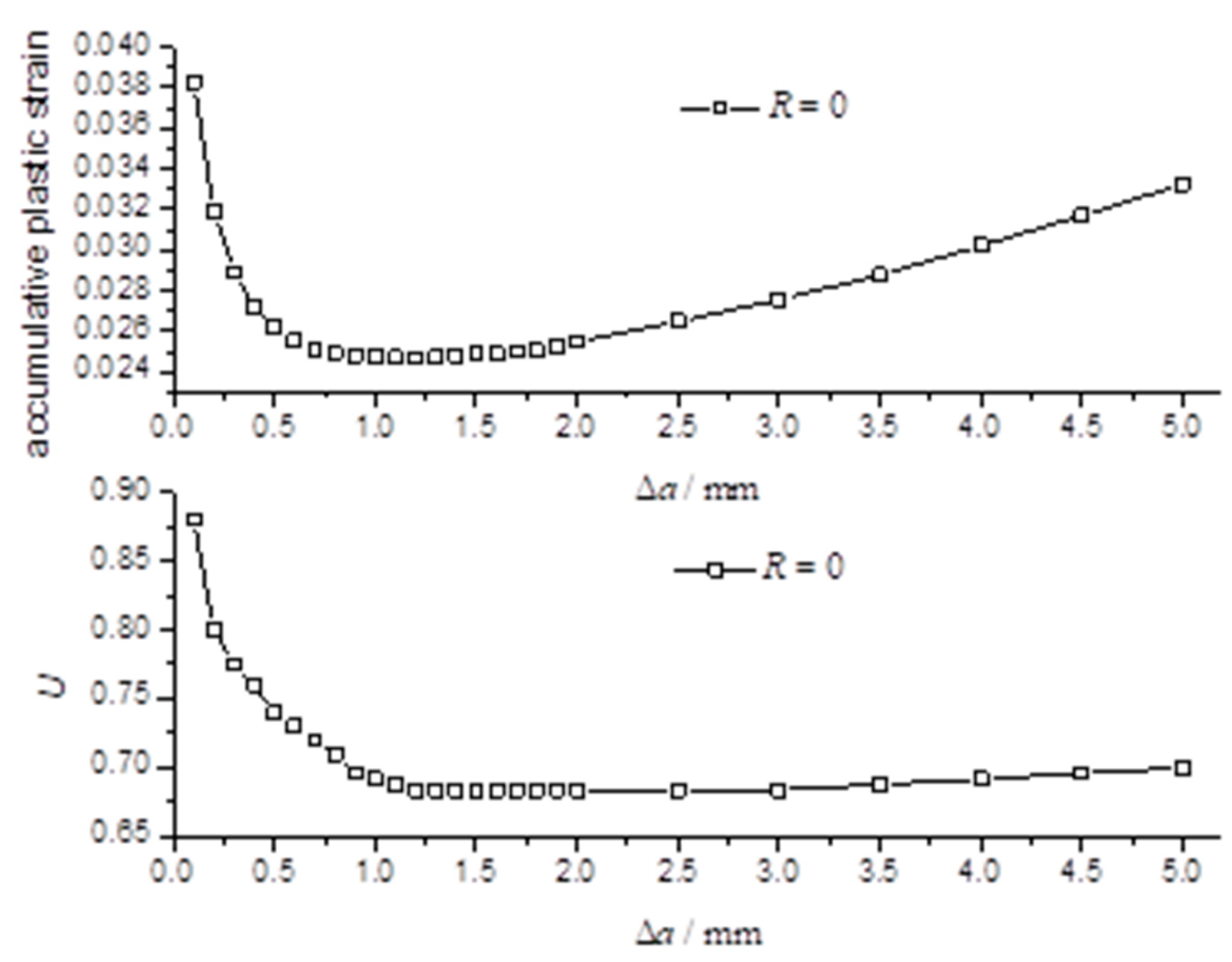
3.4. Relationship between Accumulative Plastic Strain and Crack Closure Parameter

3.4.1. Study of Crack Closure Mechanism and Evolution of Accumulative Plastic Strain

The phenomenon of crack closure is closely linked to the accumulative plastic strain at the crack tip. When a crack propagates, the plastic zone ahead of the crack tip affects the formation of the trailing zone, while the crack closure effect influences the stress–strain distribution in the vicinity of the crack tip, thus slowing down the crack growth rate. The accumulative plastic strain at the crack tip has two impacts on the crack closure phenomenon. Firstly, it affects the current crack length’s crack closure effect, and secondly, it influences the residual compressive stress field in the trailing zone of the new crack tip after crack propagation due to the irrecoverable deformation formed at the previous crack tip, which in turn affects the crack closure effect.
Based on Figure 11, it can be observed that the accumulative plastic strain at the crack tip experiences a peak value, followed by a decreasing trend, which is primarily influenced by the preceding hardening process [42]. The initial peak value of the accumulative plastic strain plays a significant role in facilitating crack closure, while the residual trailing zone gradually forms as the crack propagates. As a result, the residual compressive stress in the trailing zone becomes the primary source of crack closure. During the initial stage of crack propagation, the accumulative plastic strain at the crack tip first decreases and then stabilizes, with a corresponding decrease and stabilization of the crack closure parameter. This indicates that the stability of the accumulative plastic strain is closely related to the crack closure effect. As the crack continues to propagate, the accumulative plastic strain at the crack tip slowly increases, while the crack closure parameter remains unchanged. Once the crack length reaches a certain point, the accumulative plastic strain at the crack tip becomes larger, causing the crack closure parameter to exhibit a slow increase. In a related study [43], the reduction of the crack closure effect typically occurs only when the crack length is longer, but their study involves low load levels. In contrast, the present study involves higher low cycle fatigue loads, suggesting that the reduction in the closure effect may occur earlier under higher load levels.

3.4.2. The Evolution of Residual Compressive Stress Field

The portion of the crack surface that is closed can bear some of the load, which reduces the stress–strain field at the crack tip and consequently lowers the level of accumulative plastic strain. Conversely, an increase in accumulative plastic strain can result in a lower crack contact stress, which leads to a reduced crack closure effect. These two factors have a reciprocal influence on each other. The residual compressive stress field in the trailing zone is the primary determinant of the level of crack closure. Therefore, investigating the relationship between the accumulative plastic strain at the crack tip and the residual compressive stress field in the trailing zone can indirectly reveal the connection between the accumulative plastic strain at the crack tip and the crack closure effect.
The stress distribution near a crack tip was studied at minimum load for a stress ratio of R = 0, with different crack lengths. The relationship between the accumulative plastic strain and the residual compressive stress field at the crack tip was analyzed in Figure 12. Figure 12a indicates that as the crack length increased from 0.6 mm to 1.2 mm, the accumulative plastic strain decreased initially, but then stabilized. Meanwhile, the residual compressive stress increased consistently, which aligns with the observation that the crack closure parameter decreased and the crack closure effect increased. In Figure 12b, when the crack length increased from 1.2 mm to 1.8 mm, there was no significant change in the accumulative plastic strain or the corresponding residual compressive stress field. As a result, there was no notable effect on the crack closure effect, and the crack closure parameter remained stable. Figure 12c showed that as the crack length grew from 1.8 mm to 4.5 mm, the accumulative plastic strain increased continuously, while the residual compressive stress decreased slowly. This decrease is a crucial factor behind the reduction in the crack closure effect.
According to the above analysis, it is concluded that the residual compressive stress field in the trailing zone is more indicative of the level of crack closure. As the accumulative plastic strain at the crack tip increases, the residual compressive stress decreases, which in turn reduces the effectiveness of crack closure.

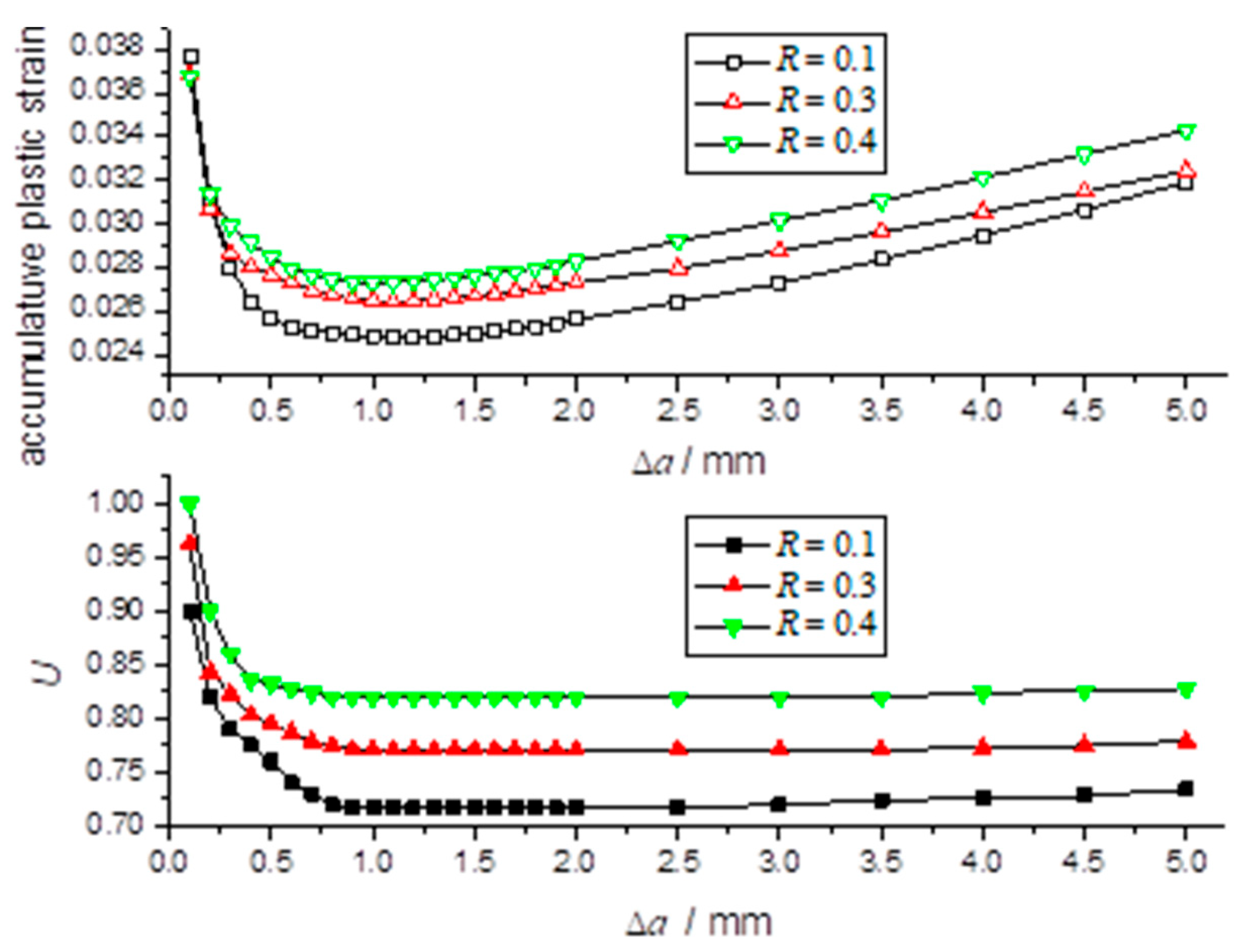
3.4.3. The Effect of the Stress Ratio

Figure 13 shows the effect of the stress ratio on accumulative plastic strain and crack closure parameters. It can be observed that when the stress ratios are 0.1, 0.3, and 0.4, the corresponding crack closure parameters at steady state are 0.717, 0.771, and 0.82, respectively. The corresponding range of decrease in accumulative plastic strain is 1.29%, 1.04%, and 0.95%, respectively. It is evident that a smaller stress ratio results in a smaller crack closure parameter, as well as a greater reduction in the range of accumulative plastic strain. The data suggest that an increase in the crack closure effect can lead to a decrease in accumulative plastic strain, with both factors tending to stabilize at a later stage. Additionally, the length of the crack has an influence on its propagation behavior. During the final stages of crack propagation, an increase in accumulative plastic strain may hinder the crack closure effect, causing the crack closure parameter to gradually increase. This trend is primarily due to a decline in the residual compressive stress field behind the crack tip.

4. Conclusions

A study was conducted to examine the behavior of crack propagation of cracked plates subjected to low cycle fatigue loads. Both experimental and numerical methods were employed to investigate the effect of the stress ratio and the initial crack length on the crack propagation process. The findings shed new light on the low cycle fatigue crack propagation behavior and offer a fresh perspective for future research. Some conclusions can be drawn:
(1) The test was conducted on AH32 steel plates to investigate the effect of maximum applied load and stress ratio on crack growth behavior. The results show that the increasing maximum applied load and decreasing stress ratio will shorten the fatigue life of cracked plates.
(2) A numerical analysis of a cracked plate was carried out to study the distribution of the stress–strain field and crack closure parameter. The study found that an increase in the stress ratio led to a rise in the residual compressive stress in the trailing zone, resulting in lengthened crack closure and an amplified effect. Additionally, the crack closure effect and accumulative plastic strain at the crack tip influenced the crack growth rate.
(3) The crack closure effect is influenced by the residual compressive stress in the trailing zone. Higher residual compressive stress enhances the effect, while crack closure weakens the stress–strain field at the crack tip, suppressing accumulative plastic deformation. As accumulative plastic deformation increases, the compressive stress in the trailing zone decreases, weakening the closure effect. This interaction is important for studying low cycle fatigue.

Author Contributions

Study design and manuscript writing D.Q., Literature search and article translation, X.G.; Making charts and data analysis, Z.J.; Revision, H.Y. All authors have read and agreed to the published version of the manuscript.

Funding

This research was funded by the National Natural Science Foundation of China (grant no. 51909198), The Natural Science Foundation of Hubei Province (Grant No.2022CFB331), the Fundamental Research Funds for the Central Universities (WUT: 3120622721), The Natural Science Foundation of the Jiangsu Higher Education Institutions of China (23KJB58005).

Institutional Review Board Statement

Not applicable.

Informed Consent Statement

Not applicable.

Data Availability Statement

Due to the nature of this research, participants of this study did not agree for their data to be shared publicly, so supporting data is not available.

Acknowledgments

The authors acknowledge the financial support provided by The National Natural Science Foundation of China (Grant No.51909198), The Natural Science Foundation of Hubei Province (Grant No.2022CFB331), the Fundamental Research Funds for the Central Universities (WUT: 3120622721), and The Natural Science Foundation of the Jiangsu Higher Education Institutions of China (23KJB58005).

Conflicts of Interest

The authors declare no conflict of interest.

References

  1. Coffin, L. A Study of the Effects of Cyclic Thermal Stresses on a Ductile Metal. J. Fluids Eng. 1954, 76, 931–949. [Google Scholar] [CrossRef]
  2. Dunham, F.W. Fatigue testing of large-scale models of submarine structural details. Mar. Technol. 1965, 1, 299–307. [Google Scholar] [CrossRef]
  3. Jordan, C.R.; Cochran, C.S. In-service performance of structural details. Ship Struct. Comm. 1978, 272, 1–9. [Google Scholar]
  4. Jordan, C.R.; Cochran, C.S. Further survey of in-service performance of structural details. Ship Struct. Comm. 1980, 294, 2–10. [Google Scholar]
  5. Munse, W.; Wilbur, T.; Tellalian, M.; Nicoll, K.; Wilson, K. Fatigue characterization of fabricated ship detail for design. Ship Struct. Comm. 1982, 318, 1–10. [Google Scholar]
  6. Radek, P.; Jan, D. Low cycle fatigue properties assessment for rotor steels with the use of miniaturized specimens. Int. J. Fatigue 2022, 154, 106555. [Google Scholar]
  7. Morishita, T.; Itoh, T.; Sakane, M.; Nakamura, H.; Takanashi, M. Multiaxial fatigue property of Ti–6Al–4V using hollow cylinder specimen under push-pull and cyclic inner pressure loading. Int. J. Fatigue 2016, 87, 370–380. [Google Scholar] [CrossRef]
  8. Itoh, T.; Nakamura, H.; Takanashi, M.; Wu, M. Multiaxial low cycle fatigue life of Ti-6Al-4V under non-proportional loading with mean strain. Theor. Appl. Fract. Mech. 2017, 90, 165–173. [Google Scholar] [CrossRef]
  9. Chen, L.; Chen, X. The low cycle fatigue tests on submarine structures. Ship Sci. Technol. 1991, 2, 19–20. [Google Scholar]
  10. Urm, H.; Yoo, I.; Heo, J. Low cycle fatigue strength assessment for ship structures. In Proceedings of the 9th Symposium on Practical Design of Ships and Other Floating Structures, Travemuende, Germany, 12–17 September 2004; pp. 774–781. [Google Scholar]
  11. Han, Y.; Cui, W.; Huang, X.; Wu, Y. Fatigue strength assessment of large-scale ship structures. Shipbuild. China 2007, 48, 60–67. [Google Scholar]
  12. Liu, Y.; Zhu, X.; Huang, X. Experimental research on low frequency fatigue crack propagation rate of 921A hull steel structure. J. Nav. Univ. Eng. 2008, 20, 69–74. [Google Scholar]
  13. Wang, Q.; Huber, N.; Liu, X.; Kashaev, N. On the analysis of plasticity induced crack closure in welded specimens: A mechanism controlled by the stress intensity factor resulting from residual stresses. Int. J. Fatigue 2022, 162, 106940. [Google Scholar] [CrossRef]
  14. Masoud, S.; Otmar, K. A novel approach for determining the stress intensity factor for cracks in multilayered cantilevers. Eng. Fract. Mech. 2022, 266, 108386. [Google Scholar]
  15. Hossein, N.; Pooya, R. Stress concentration factors in tubular T-joints reinforced with external ring under in-plane bending moment. Ocean Eng. 2022, 266, 112551. [Google Scholar]
  16. Hossein, N.; Pooya, R. Probabilistic analysis of the SCFs in tubular T/Y-joints reinforced with FRP under axial, in-plane bending, and out-of-plane bending loads. Structures 2022, 35, 1078–1097. [Google Scholar]
  17. Hossein, N.; Pooya, R. Stress concentration factors in tubular T/Y-connections reinforced with FRP under in-plane bending load. Mar. Struct. 2021, 76, 102871. [Google Scholar]
  18. Hossein, N.; Pooya, R. Static capacity of tubular X-joints reinforced with fiber reinforced polymer subjected to compressive load. Eng. Struct. 2021, 236, 112041. [Google Scholar]
  19. Hossein, N.; Pooya, R. Stress concentration factors in tubular T/Y-joints strengthened with FRP subjected to compressive load in offshore structures. Int. J. Fatigue 2020, 140, 105719. [Google Scholar]
  20. Dong, Q.; Yang, P.; Xu, G. Low cycle fatigue crack growth analysis by CTOD under variable amplitude loading for AH32 steel. Mar. Struct. 2019, 63, 257–268. [Google Scholar] [CrossRef]
  21. Dong, Q.; Yang, P.; Deng, J.; Wang, D. The theoretical and numerical research on CTOD for ship plate under cyclic loading considering accumulative plastic strain. J. Ship Mech. 2015, 19, 1507–1516. [Google Scholar]
  22. Dowling, N.E. Geometry effects and the J-integral approach to elastic-plastic fatigue crack growth. In Cracks and Fracture; Swedlow, J., Williams, M., Eds.; ASTM STP 601; American Society for Testing and Materials: West Conshohocken, PA, USA, 1976; pp. 19–32. [Google Scholar]
  23. Gonzales, G.L.G.; González, J.A.O.; Antunes, F.V.; Neto, D.M.; Díaz, F.A. Experimental determination of the reversed plastic zone around fatigue crack using digital image correlation. Theor. Appl. Fract. Mech. 2023, 125, 103901. [Google Scholar] [CrossRef]
  24. Chen, J.; Huang, Y.; Dong, L.; Li, Y. A study on evaluation method of crack tip reverse plastic zone size for the center cracked steel plate model under tension-compression cyclic loading. Eng. Fract. Mech. 2015, 133, 138–151. [Google Scholar] [CrossRef]
  25. Zhang, W.; Liu, Y. Plastic zone size estimation under cyclic loadings using in situ optical microscopy fatigue testing. Fatigue Fract. Eng. Mater. Struct. 2011, 34, 717–727. [Google Scholar] [CrossRef]
  26. Huang, M.; Cai, L. Unified theoretical solutions for describing the crack-tip stress fields of finite specimens with mode-I crack under fully plastic conditions. Int. J. Solids Struct. 2022, 254–255, 111846. [Google Scholar] [CrossRef]
  27. Xu, M.; Liu, Y.; Yuan, H. Characterization of crack-tip fields for elasto-plastic fatigue crack growth Part I: Analysis of the J-integral. Eng. Fract. Mech. 2022, 275, 108847. [Google Scholar] [CrossRef]
  28. Ding, X.; Yan, X.; Guo, Z.; Guo, K. A combined low- and high-cycle life prediction model considering the closure effect of micro-defects. Fatigue Fract. Eng. Mater. Struct. 2022, 45, 2058–2071. [Google Scholar] [CrossRef]
  29. Mansor, N.; Abdullah, S.; Ariffin, A. Effect of loading sequences on fatigue crack growth and crack closure in API X65 steel. Mar. Struct. 2019, 65, 181–196. [Google Scholar] [CrossRef]
  30. Ferreira, S.; Castro, J.; Meggiolaro, M.A.; de Oliveira Miranda, A.C. Crack closure effects on fatigue damage ahead of crack tips. Int. J. Fatigue 2019, 125, 187–198. [Google Scholar] [CrossRef]
  31. Ma, T.; Gao, N.; Chang, L.; He, X.; Zhou, C. Low-cycle fatigue behavior and life prediction of CP-Ti under non-proportional and multiaxial loading. Eng. Fract. Mech. 2021, 254, 107930. [Google Scholar] [CrossRef]
  32. Deng, J.; Tu, W.; Xiong, K.; Yang, P.; Dong, Q. Analysis of biaxial proportional low-cycle fatigue and biaxial accumulative plasticity of hull inclined-crack plate. Int. J. Nav. Archit. Ocean Eng. 2022, 14, 100423. [Google Scholar] [CrossRef]
  33. Song, Y.; Yang, P.; Peng, Z.; Jiang, W. Low-Cycle Fatigue Crack Propagation Behavior of Cracked Steel Plates Considering Accumulative Plastic Strain. Int. J. Steel Struct. 2020, 20, 538–547. [Google Scholar] [CrossRef]
  34. Jiang, W.; Yang, P.; Luo, B.; Xu, Z. Responses of cracked stiffened plates to low-cycle fatigue loads. Ocean Eng. 2021, 241, 109986. [Google Scholar] [CrossRef]
  35. Dong, Q.; Yang, P.; Xu, G.; Deng, J. Mechanisms and modeling of low cycle fatigue crack propagation in a pressure vessel steel Q345. Int. J. Fatigue 2016, 89, 2–10. [Google Scholar] [CrossRef]
  36. Tola, A.; Eatherton, M.; Koutromanos, L. Experimental program for characterization of ultra-low cycle fatigue fracture in structural steel. Eng. Fract. Mech. 2022, 276, 108873. [Google Scholar] [CrossRef]
  37. Chen, J.; Xiao, X.; Xiong, S.; Wang, J.; Huang, H.; Yang, B. Low cycle fatigue behavior of Cu-Cr-Zr alloy with different cold deformation. Fatigue Fract. Eng. Mater. Struct. 2023, 46, 3–16. [Google Scholar] [CrossRef]
  38. Xiong, K.; Deng, J.; Pei, Z.; Tang, H.; Tu, W. Analysis of accumulative plasticity and fracture behavior of hull cracked plates subjected to biaxial low cycle fatigue loading. J. Ship Mech. 2022, 26, 113–124. [Google Scholar]
  39. Dong, Q.; Rong, M.; Xu, G. Study of crack closure effect of hull plate under low cycle fatigue. J. Mar. Sci. Eng. 2022, 10, 1557. [Google Scholar] [CrossRef]
  40. Gan, J.; Sun, D.; Deng, H.; Wang, Z.; Wang, X.; Yao, L.; Wu, W. Fatigue characteristics of designed T-type specimen under two-step repeating variable amplitude load with low-amplitude load below the fatigue limit. J. Mar. Sci. Eng. 2021, 9, 107. [Google Scholar] [CrossRef]
  41. E647-05; Standard Test Method for Measurement of Fatigue Crack Growth Rates. ASTM: West Conshohocken, PA, USA, 2005.
  42. Rodrigues, D.; Antunes, F. Finite element simulation of plasticity induced crack closure with different material constitutive models. Eng. Fract. Mech. 2009, 76, 1215–1230. [Google Scholar] [CrossRef] [Green Version]
  43. Zhou, L.; Wang, J.; Wang, Y.; Li, X.; Chai, Y. The enriched finite element method-virtual crack closure technique for cracked structures. Thin-Walled Struct. 2023, 187, 110756. [Google Scholar] [CrossRef]
Figure 1. The geometric dimensions of central cracked plate.
Jmse 11 01436 g001
Figure 2. Scheme of fatigue crack growth test.
Jmse 11 01436 g002
Figure 3. The fatigue life vs. crack length.
Jmse 11 01436 g003
Figure 4. The fatigue life vs. COD.
Jmse 11 01436 g004
Figure 5. The fracture morphology of cracked plate.
Jmse 11 01436 g005
Figure 6. FE model and refined mesh.
Jmse 11 01436 g006
Figure 7. Comparison of stress–strain curves.
Jmse 11 01436 g007
Figure 8. The variation of COD (a) at minimum applied load and (b) at maximum load.
Jmse 11 01436 g008
Figure 9. The distribution of crack tip stress field (a) at minimum applied load and (b) at maximum load.
Jmse 11 01436 g009
Figure 10. The crack closure level under different stress ratios.
Jmse 11 01436 g010
Figure 11. Relationship between accumulative plastic strain and crack closure parameter.
Jmse 11 01436 g011
Figure 12. The stress distribution at minimum applied load.
Jmse 11 01436 g012
Figure 13. The effect of stress ratio.
Jmse 11 01436 g013
Table 1. Mechanical behavior for AH32 steel.
Yield   Stress   ( MPa ) Ultimate   Tensile   Strength   ( MPa ) Elastic   Modulus   ( GPa )
E
Poisson’s Ratio
ν
3455102060.3
Table 2. Loading conditions and experimental results of AH32 steel.
Specimen No. P max / kN Stress Ratio RFatigue Life
019502142
02950.12455
03950.24670
041000.23425
Table 3. Parameters of the Chaboche model.
E = 206 GPa        V = 0.3        Q = 72 MPa        k = 8 MPa
C1 = 314,310       C2 = 28,071       C3 = 1950
α1 = 800       α2 = 321           α3 = 0
Table 4. Results of convergence study.
Mesh SizeCrack Closure Parameter UDifference/%
0.1 × 0.1 mm0.7251.11
0.05 × 0.05 mm0.717-
0.02 × 0.02 mm0.7130.56
Disclaimer/Publisher’s Note: The statements, opinions and data contained in all publications are solely those of the individual author(s) and contributor(s) and not of MDPI and/or the editor(s). MDPI and/or the editor(s) disclaim responsibility for any injury to people or property resulting from any ideas, methods, instructions or products referred to in the content.

