Abstract
Bows and stems are often subjected to wave slamming loads. Stiffened plates with curvatures in both longitudinal and transversal directions are the basic members of these structures. As a result, it is important to investigate the lateral ultimate strength of the doubly curved stiffened plates. In this study, the non-linear finite element method (NFEM) is selected to investigate the collapse modes and lateral ultimate strengths of the doubly curved stiffened plates. Additionally, the influences of curvature and geometrical properties on the collapse modes and ultimate strengths of doubly curved stiffened plates are investigated. In the NFEM analysis, a series of numerical simulations, covering different aspect ratios, curvatures, and structural scantlings are performed. Different collapse modes of doubly curved stiffened plates under lateral loading cases are observed. The relationships between the collapse modes and the geometrical properties are then discussed based on the numerical results. Moreover, the results also show that larger curvatures along the stiffeners and stronger stiffeners contribute more to the lateral ultimate strengths. Subsequently, an empirical formula is derived and verified for predicting the lateral ultimate strength of the doubly curved stiffened plates. The results of the empirical formula match well with numerical calculations.
1. Introduction
Complicated curved surfaces exist in ship structures, e.g., the bow, stem, and hull surfaces exhibit varying curvatures. Consequently, stiffened plates with curvatures in both longitudinal and transversal directions are employed in these structures. In recent years, there has been increasing interest from both industry and academia in the structural ultimate strength and reliability of bows and stems.
Ultimate strengths of bows and stems are very important in the evaluation of ship structures, especially in ship–ice collision and wave slamming cases. Yang et al. [1] researched the dynamic behaviors of the large container ship’s bow structures subjected to slamming pressures; a safety margin evaluating the safety performance of large container ships under a slamming pressure coefficient was presented. Shabani et al. [2] investigated the slamming loads and kinematics during bow entry events and derived an advanced central bow designing method. In such cases, lateral loads with large amplitudes are applied to doubly curved stiffened plates which constitute structures. The plates face the risk of global buckling, which can result in the collapse of the entire structure. Therefore, it is crucial to conduct further research on the ultimate strength issues associated with such scenarios. Moreover, doubly curved stiffened plates are the basic units of ship structures with complicated curved surfaces, of which the collapse mechanisms are not exactly the same as with flat stiffened plates or singly curved stiffened plates. Related research into doubly curved stiffened plates has seldom been reported.
Research on the ultimate strengths and collapse mechanisms of flat stiffened plates serves as a valuable reference for studying curved stiffened plates. Numerous empirical formulae have been developed to conveniently obtain the ultimate strength of the plates or stiffened plates. Liu and Zhang [3] analyzed the influence of the rotational stiffness, aspect ratio, and initial deflection on the ultimate strengths of plates subjected to axial compressions, and a modified empirical formula containing the above factors was proposed. Hayward and Lehmann [4] presented a new formula of the load-bearing capacity of plates under biaxial loads, which can capture the influences of the plate slenderness and aspect ratio. Kim et al. [5] reviewed the well-known formula, predicting the ultimate strength of stiffened plates by comparing it with analytical and FEA results, and proposed the ultimate strength empirical formula without considering the fluctuation behavior. Li et al. [6,7] presented an adapted algorithm to predict the stiffened plates’ collapse progress, which extends the predicting capacity of the elastic stiffness and ultimate and post-ultimate features. The ultimate strength of stiffened plates subjected to the combined longitudinal compressive stress and lateral pressure has also been studied, with corresponding numerical analysis, empirical formulae, and experiments. Yao et al. [8] explored the effect of the boundary conditions on the ultimate strength of stiffened panels under the combined action of longitudinal and lateral loads.
Many investigations on collapse behaviors of plane stiffened plates have also been performed, through which several typical collapse modes, deformation mechanisms, and some recommending modeling techniques have been explored. Paik [9] explored six kinds of collapse modes for stiffened plates under different load cases and derived a series of empirical formulae for combined load cases. Ma et al. [10] explored the influence of lateral loads on ultimate strengths and collapse modes of stiffeners under combined load cases and provided a useful explanation about different collapse modes of stiffeners. Xu et al. [11] performed a series of NFEM analyses and investigated the influence of boundary conditions on collapse behaviors of the stiffened plates under different load cases. Li et al. [12,13] investigated the deformation behaviors of continuous plates under combined biaxial loads and lateral pressure. The loading components include both constant loads and cyclic loads.
By taking transversal curvature into account, many studies on singly curved stiffened plates have been conducted. Cui et al. [14] investigated the ultimate strength and collapse behaviors under different load cases of single-curved stiffened plates from cargo containers and derived a series of empirical formulae for predicting the axial ultimate strength of the single-stiffened plates. Park et al. [15] researched the fundamental buckling behaviors of cylindrically curved plates subjected to axial loading and investigated the effects of the curvature, magnitude of initial imperfection, slenderness ratio, and aspect ratio on the characteristics of the buckling and post-buckling collapse behavior of cylindrically curved plates. Seo et al. [16] researched the influence of curvatures on the buckling/post-buckling characteristics and collapse behaviors of singly curved stiffened plates under axial compression and then derived relevant formulae on axial strengths. Park et al. [17] performed a series of elastic-plastic large deflection analyses on singly curved stiffened plates to clarify the fundamental behaviors of cylindrically curved plates under axial compression and lateral pressure. A double beta formula considering secondary buckling behaviors was derived based on the results. Cho et al. [18] performed an experiment on singly curved stiffened plates and investigated the influence of the curvature effect on the ultimate strengths of the single-curved stiffened plates. Research on the collapse modes and ultimate strengths of flat or singly curved stiffened plates has laid a foundation for studying doubly curved stiffened plates. The methodologies, concepts, and ultimate strengths’ influencing factors involved in these studies are instructive.
In this study, the collapse behaviors and ultimate strengths of doubly curved stiffened plates under lateral loading cases are investigated. Considering different kinds of ship structures, the influences of varying types of stiffeners, longitudinal and transversal curvatures, and geometric scantlings on the ultimate strengths and collapse modes are taken into account. Based on above influential factors studies, a prediction formula for lateral ultimate strengths of such structures has been derived and verified, resulting in good accuracy with simple form. The results from this research can be helpful for the understanding of doubly curved panels’ ultimate strength and collapse behavior as well as its contribution to the ultimate strengths of ship structures with complicated curved surfaces.
2. Methodology
In this study, the geometrical parameters of doubly curved stiffeners are firstly obtained according to the data from different ships. The NFEM models of the doubly curved with different slenderness ratios are established in the next step. Then, the lateral ultimate strengths and collapse modes of the models are obtained via the NFEM. Finally, an empirical formula of the doubly curved stiffened plates’ lateral ultimate strength is derived.
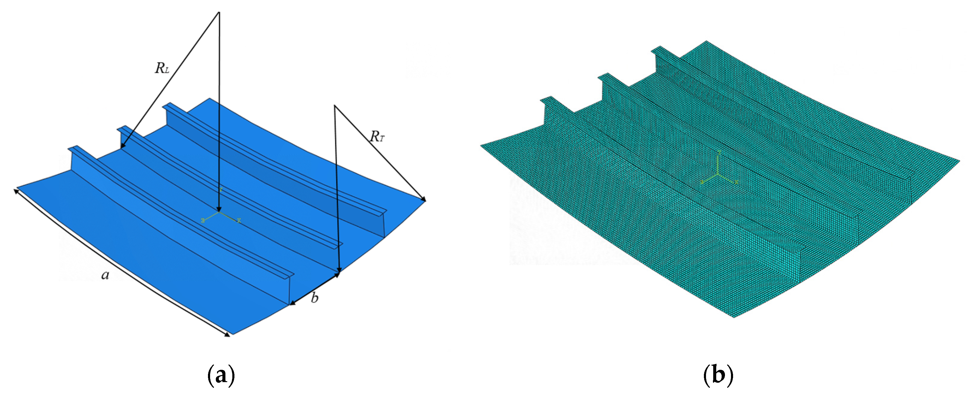
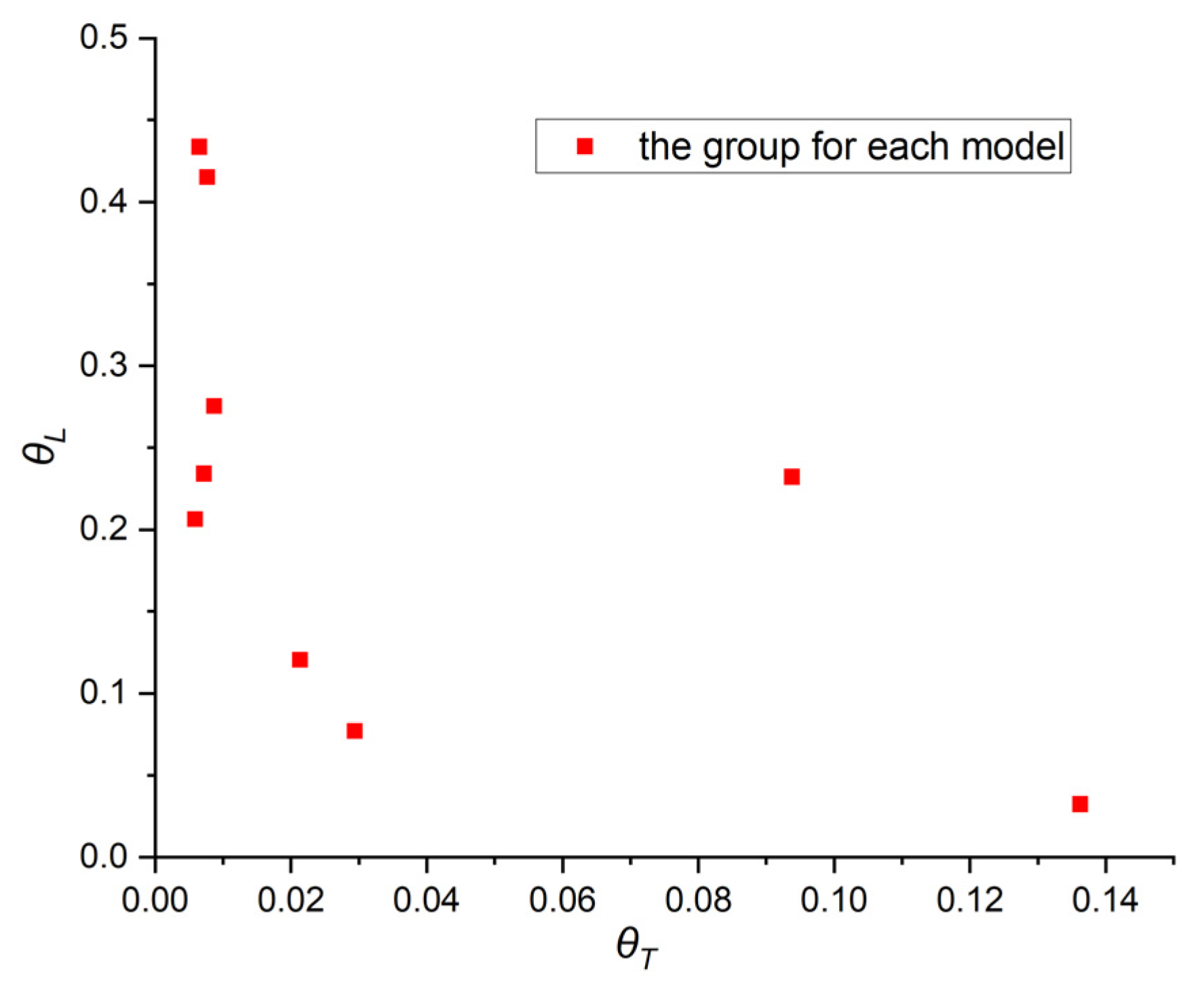
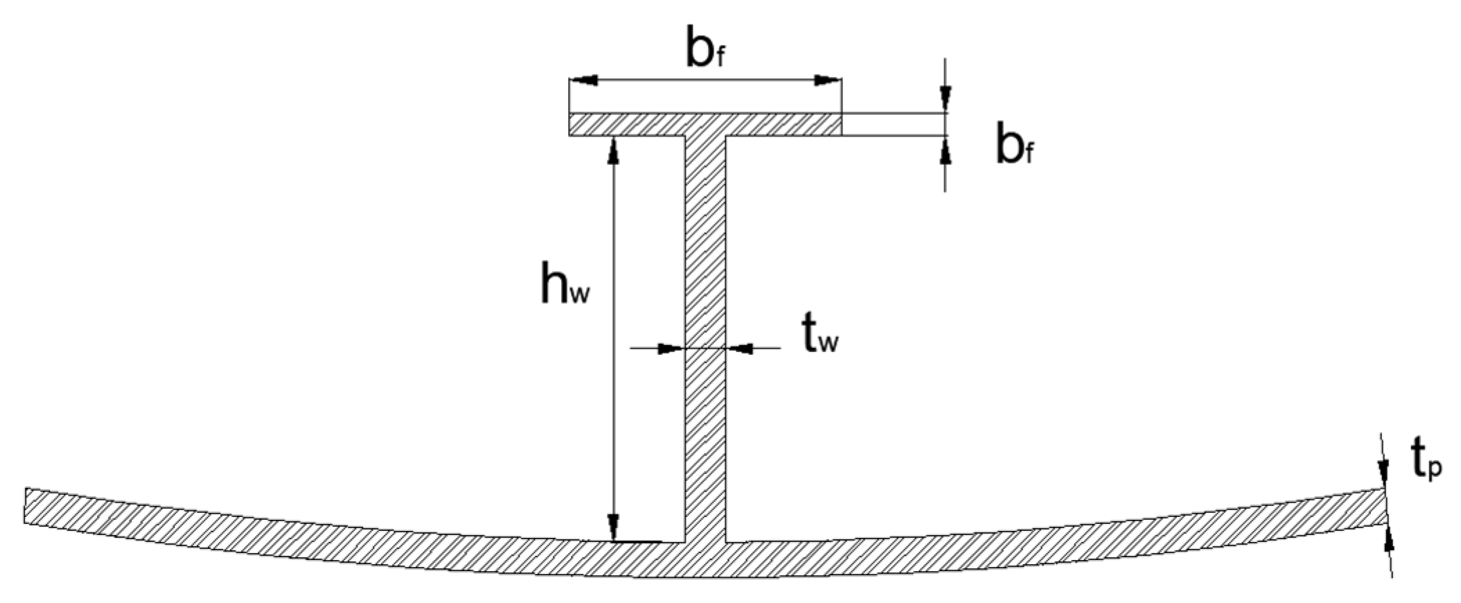
2.1. Description of Doubly Curved Stiffened Plate
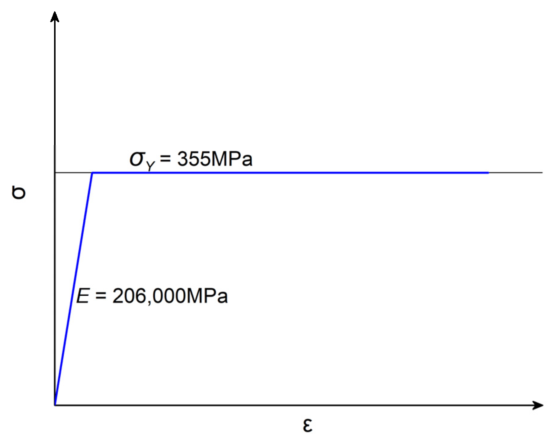
Doubly curved stiffened plates make up the complex surfaces of bows and stems, and they contribute to the strengths and the loading capacities of the structures. Such stiffened plates have curvatures in both the longitudinal and transversal directions, and the plates form complicated curved surfaces with varying curvatures. The stiffened plates in this study are selected as single span and single bay models. According to the recommendation of ISSC (2012) [19], such a model extent is acceptable. As such, stiffened plates are supported by transversal and longitudinal primary supporting members (PSMs), and, in the case of lateral loading, the boundary conditions of the stiffened structures at the PSMs can be regarded as clamped supported. Considering the background of this study, several stiffened plates derived from the bows and stems of an icebreaker, an oil tanker, and a cargo container are selected as references models. Models with different curvatures are set to explore the influence of curvature on the ultimate strengths of doubly curved stiffened plates. The structural settings of the models are shown in Figure 1, and the original geometric parameters can be found in Table 1. And the parameters appear in this research are shown in Nomenclature Section, where units for geometry and stress are mm and MPa, respectively. The detailed structural settings of the models in this research can be found in Appendix A.
Figure 1.
Structural settings of typical doubly curved stiffened plates: (a) geometric model; (b) NFEM model.
Table 1.
Structural settings of the original doubly curved stiffened plates models for this study.
As shown in Figure 1a, a denotes the longitudinal span, b denotes the spacing between adjacent stiffeners, denotes the curvature radius along the stiffeners, and denotes the curvature radius along the direction that is perpendicular to the stiffeners. To illustrate the curvature and its influence on the ultimate strengths, the curvatures in longitudinal and transversal directions of all the models are represented by groups of dimensionless terms and , which are shown in Figure 2. All the stiffeners are equipped with a ‘T’ type section, which is depicted in Figure 3.
Figure 2.
The curvature radiuses of the stiffened plate models.
Figure 3.
The dimensions of the section of the stiffener.
As there is curvature in the longitudinal or transversal direction, Seo et al. [16] investigated the singly curved stiffened plate and concluded that the ultimate strengths of such plates are related to the slenderness of flat plates with identical geometric dimensions. Therefore, the structural strengths of doubly curved stiffened plates can be evaluated by the slenderness ratios and , where denotes the column slenderness ratio of stiffener with attached plating and denotes the slenderness ratio of plating between stiffeners, which are expressed by Equation (1):
To clarify the influence of initial imperfections on lateral ultimate strengths, a curved stiffened plate with transversal curvature identical to model ‘R5’ is established. The ‘buckling’ mode initial imperfection recommended by ISSC [19] and the ‘thin horse’ mode initial imperfection conducted by Yao et al. [20] are applied to the model, respectively. The modes of the initial deflections are depicted in Figure 4 and Equations (2)–(5). As shown in Figure 5, the lateral strengths of models with different geometrical imperfections are similar. Moreover, the lateral ultimate strength does not significantly decrease with the occurrence of the initial deflections, and the differences in the ultimate strengths between models with and without initial deflection are less than 5%. Consequently, the influence of the initial deflection on lateral ultimate strengths is actually limited. And the results from models without initial imperfections can be considered reasonable.
Figure 4.
The modes’ initial imperfections. (a) Buckling mode; (b) thin horse mode. Scale: 40.
Figure 5.
Influence of initial imperfections on ultimate strengths.
The column type deformation of a stiffened plate:
where denotes the magnitude of column type mode and is recommended as 0.0015a.
The initial tripping distortion of a stiffener:
The buckling mode initial deflection of local plating:
The thin horse mode initial deflection of local plating:
where are determined according to the empirical value derived by Yao et al. [20], and is shown in Table 2, and the maximum magnitude is the same as the previous buckling mode.
Table 2.
Coefficients of initial deflection magnitudes.
In shipyards, the manufacturing of doubly curved plates with complicated curvatures is achieved through the line heating technique. Consequently, the existing empirical formulae for initial imperfections such as ‘buckling’ and ‘thin horse’ are not suitable for such plates. Moreover, in actual conditions, residual stress will shake down after multiple loading and de-loading processes; thus, the influence of residual stress is negligible in a real ship structure. The calculations performed above have proved that the influence of the initial deflection is neglectable, and there are few data about the initial imperfections that are applicable for doubly curved stiffened plates. Therefore, the influence of the initial deflections and residual stress is not considered in this study.
2.2. NFEM Analysis
The computer code ABAQUS is considered as the numerical analyzing method in this study. The type of elements is chosen as S4R, which simulates the shell and possesses four nodes and six degrees of freedom. In the NFEM models, the nonlinearities of material and geometry are all taken into account. The geometrical nonlinearity is performed by the using the ‘NLGEOM’ option in the code. This option takes large deformations and the nonlinearity between displacements and strains into account. And the nonlinearity of the material is performed by considering the yielding strength in the constitutive relationship of the material. Material nonlinearity and geometric nonlinearity must be considered in research, while initial imperfection is not a mandatory input; meanwhile, there is no relevant data available for doubly curved stiffened plates, so it is not considered in this study. The property of steel is defined with the ideal elastic-plastic model (the material has no plastic strain, and the nonlinearity is realized by yielding strength, ), which is illustrated in Figure 6.
Figure 6.
The ideal elastic-plastic constitutive relationship for the steel.
Additionally, the implicit static method is applied during the calculation. As the size of the mesh has an important impact on the speed and results of the calculation, to keep a balance between the accuracy and efficiency of the calculation, an appropriate size of the mesh should be confirmed. The mesh sizes are selected as 10 mm, 15 mm, 20 mm, 25 mm, and 45 mm, respectively. As shown in Figure 7, the ultimate strength exhibits a stable state when the element sizes are within 10 mm and 20 mm. As a result, an element size of 20 mm was used in the finite element model to ensure relatively accurate results and higher calculation efficiency. Moreover, to justify the reliability of the NFEM, we also performed a comparison calculation on an axial ultimate strength problem of the standard stiffened plates conducted by ISSC 2012 [19], and the relevant information and results are shown in Table 3. The error between the results of the NFEM and ISSC is within 2.5%, signifying that the NFEM employed in this study is reliable.
Figure 7.
Results of the mesh sensitivity analysis.
Table 3.
Results of the benchmark calculation.
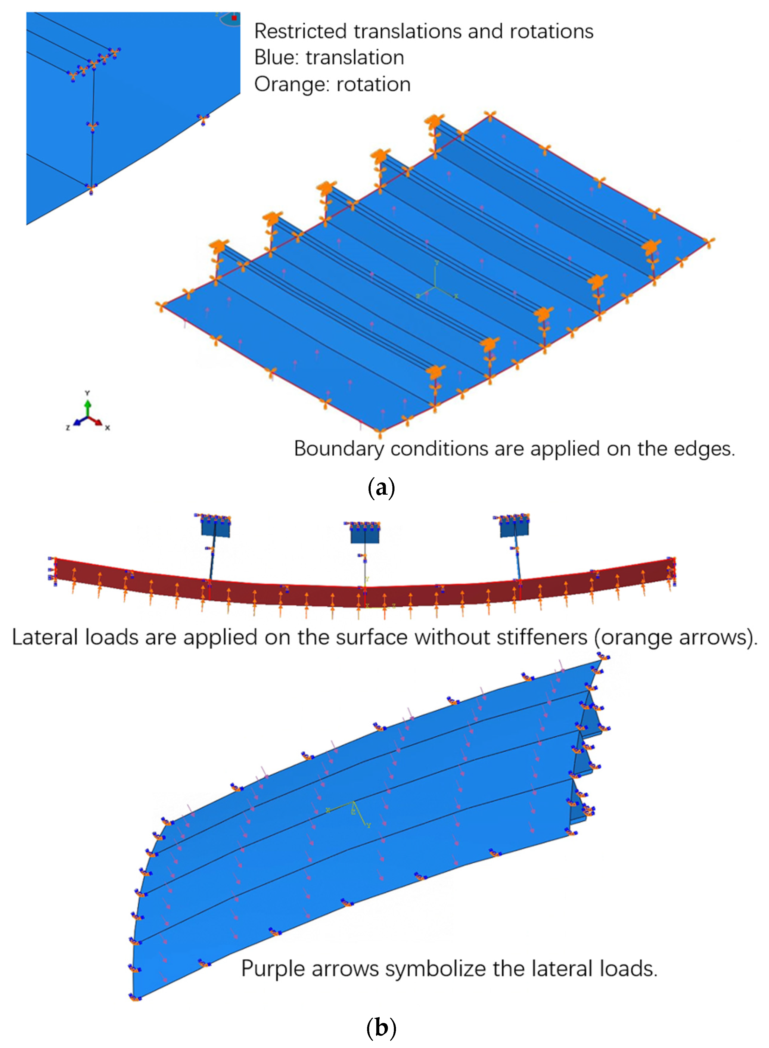
2.3. Boundary Conditions and Load Applications
The quantity of longitudinal and transversal primary supporting members in bow or stem structures is generally larger than those in other parts; therefore, doubly curved stiffened plates are subjected to stronger constraints than stiffened plates in other parts. Additionally, the deformations of the shell, when subjected to uniformly distributed lateral loads, are symmetric in longitudinal or transversal direction. Consequently, in the investigation of the lateral ultimate strength of the doubly curved stiffened plates, the clamped constraint is applied on the boundaries of the numerical model, restricting all the translations and rotations. The lateral loads are applied on the outer surface without stiffeners in the form of a uniformly distributed normal load. The settings of load and boundary conditions are shown in Figure 8.
Figure 8.
NFEM settings. (a) Boundary conditions; (b) lateral loading.
3. Results and Discussion
Based on the NFEM, a series of calculations have been performed on typical doubly curved stiffened plate models designed according to corresponding ships. The following results have been obtained by analyzing the target models with 144 different structural dimensions. The variations in the curvature radius, plate thickness, and stiffeners’ sections are considered in the design of these numerical models. According to the structural designs of target ships and the information from Zhang [21], the column slenderness of the model ranges from 0 to 1.5 and the plate slenderness ranges from 0 to 3. To describe the geometrical properties conveniently, the stiffeners are named in the form of ‘Curvature radius-Plate thickness-Stiffener’. Nine groups of curvature radiuses are represented by ‘R1’-‘R9’. In each group, four types of plate thickness and stiffeners’ sections are selected, denoted as ‘T1’–‘T4’ and ‘S1’–‘S4’, respectively, and the corresponding number represents a specific type. For example, ‘R2’ denotes these models have the same longitudinal and transversal curvature radius as those in group 2, while ‘T1’ or ‘S1’ denotes the same setting as the original model. Similarly, the model ‘R7T2S3’ signifies that the plate thickness and stiffeners’ properties differ from those of the original models.
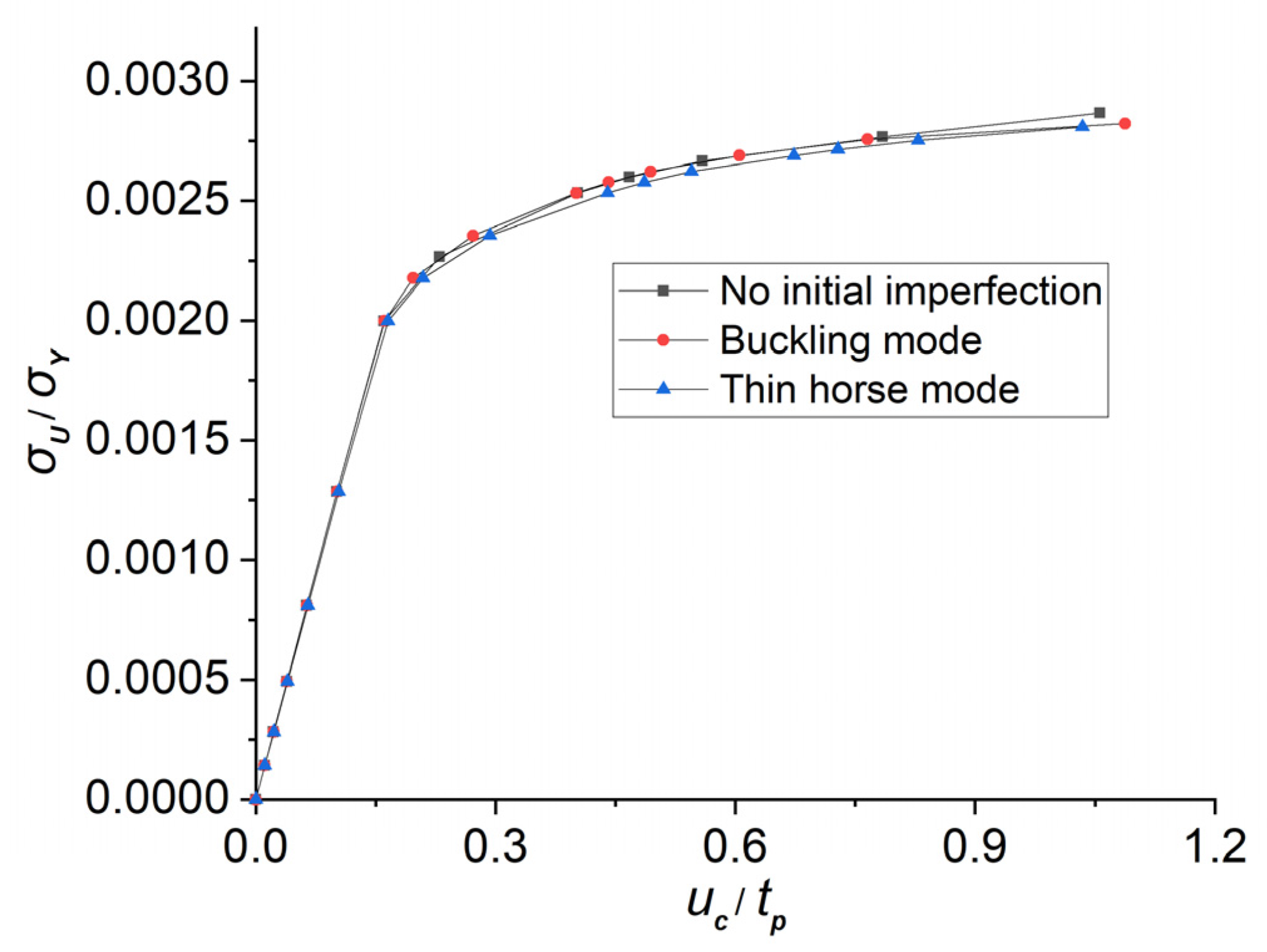
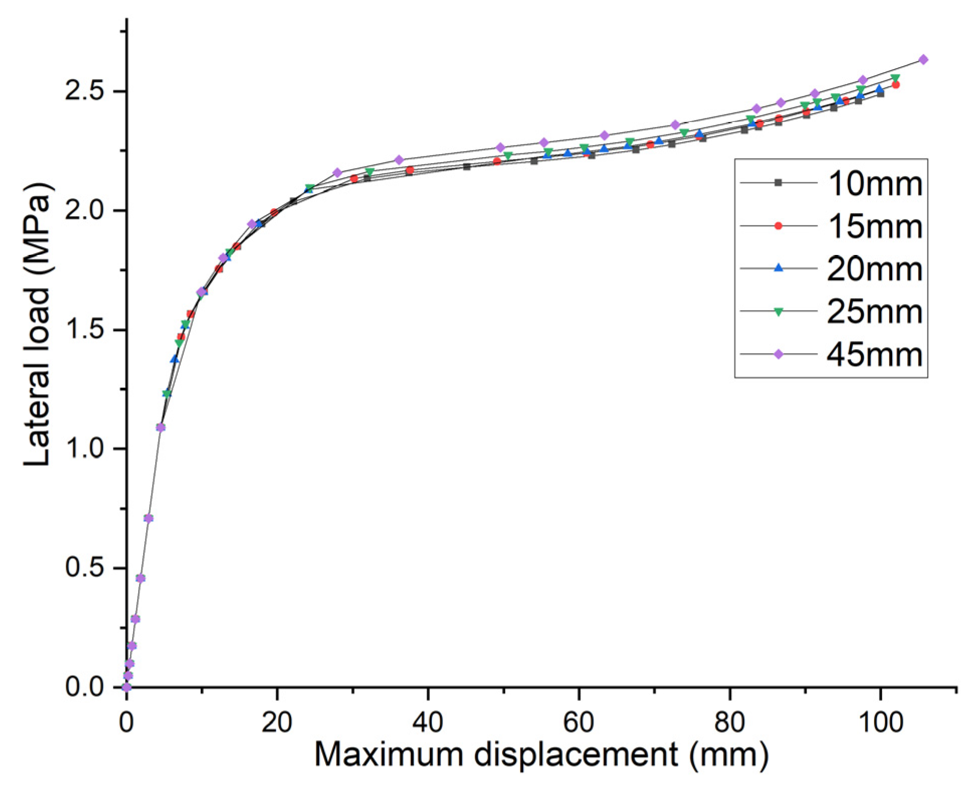
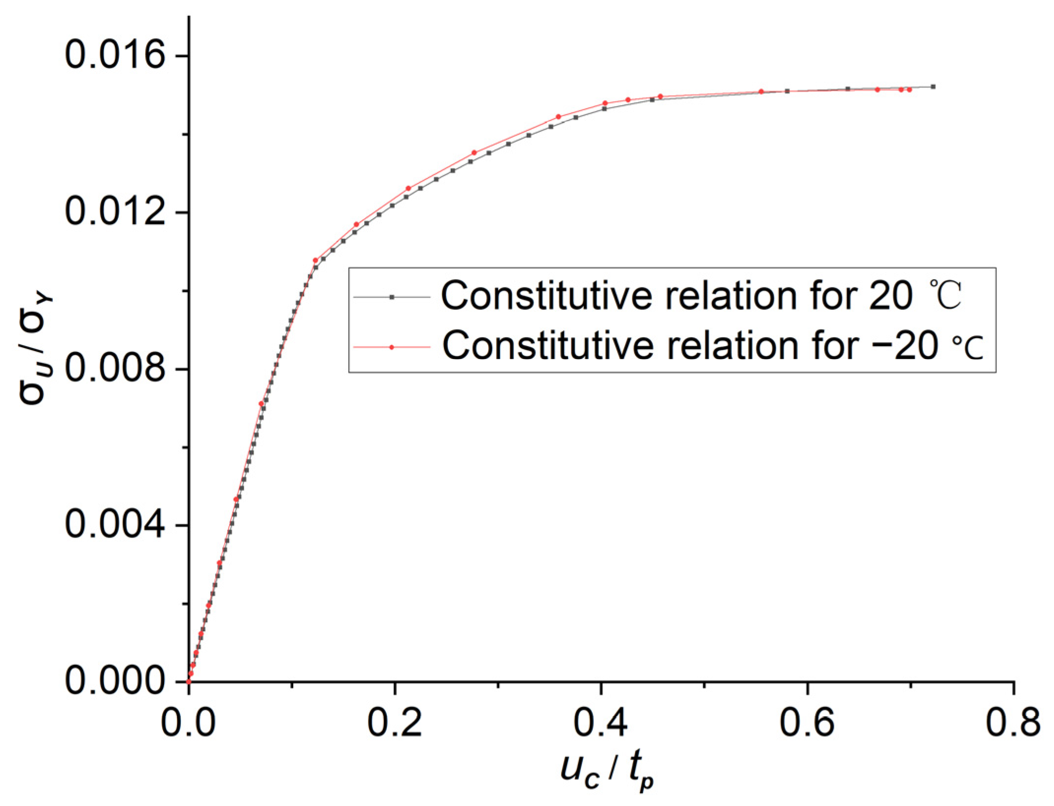
3.1. The Determination of the Lateral Ultimate Strength
In this study, the lateral ultimate strength of the doubly curved stiffened plate is determined by identifying the lateral load at the inflection point of the lateral load-central displacement curve. The magnitude displacement of the central point is selected as the response of the structure in the lateral loading cases. Figure 9b illustrates the lateral load-magnitude displacement curve for each case, where four points are selected to define two straight lines. These lines represent different parts of the curve; namely, the linear loading stage before buckling occurs and the post-buckling stage with large deformations. The lateral load at the intersection of these lines is considered as the lateral ultimate load, measured in MPa. The lateral ultimate strength and the structural response are normalized by and , respectively, where denotes the yielding stress of the material and denotes the normal displacement of the central point of the model.
Figure 9.
The definition of the lateral ultimate strength. (a) The central point of the model (the red highlighted node); (b) the determination of the lateral ultimate load.
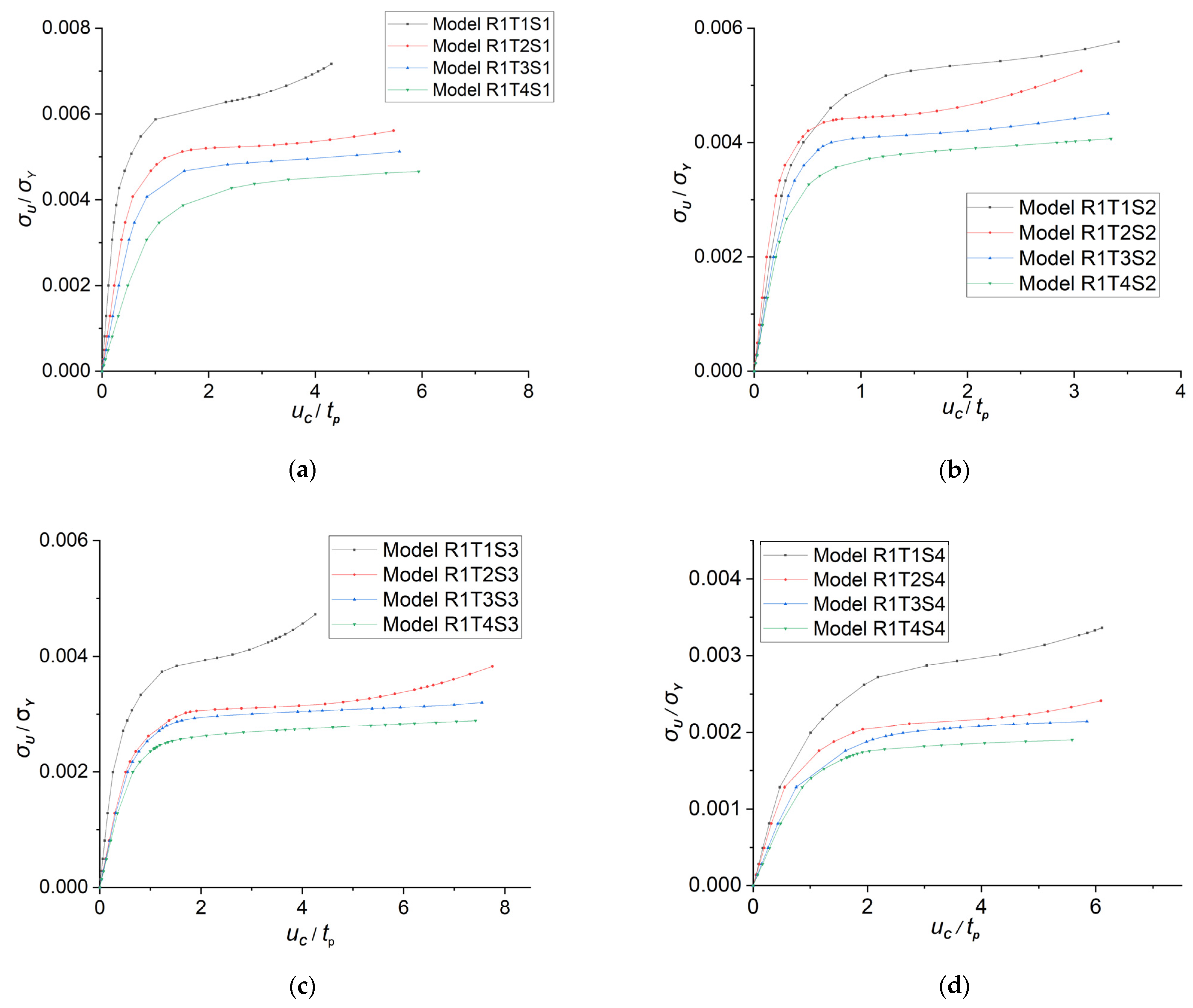
3.2. Collapse Modes and Ultimate Strength of Doubly Curved Stiffened Plates under Lateral Pressure Loading
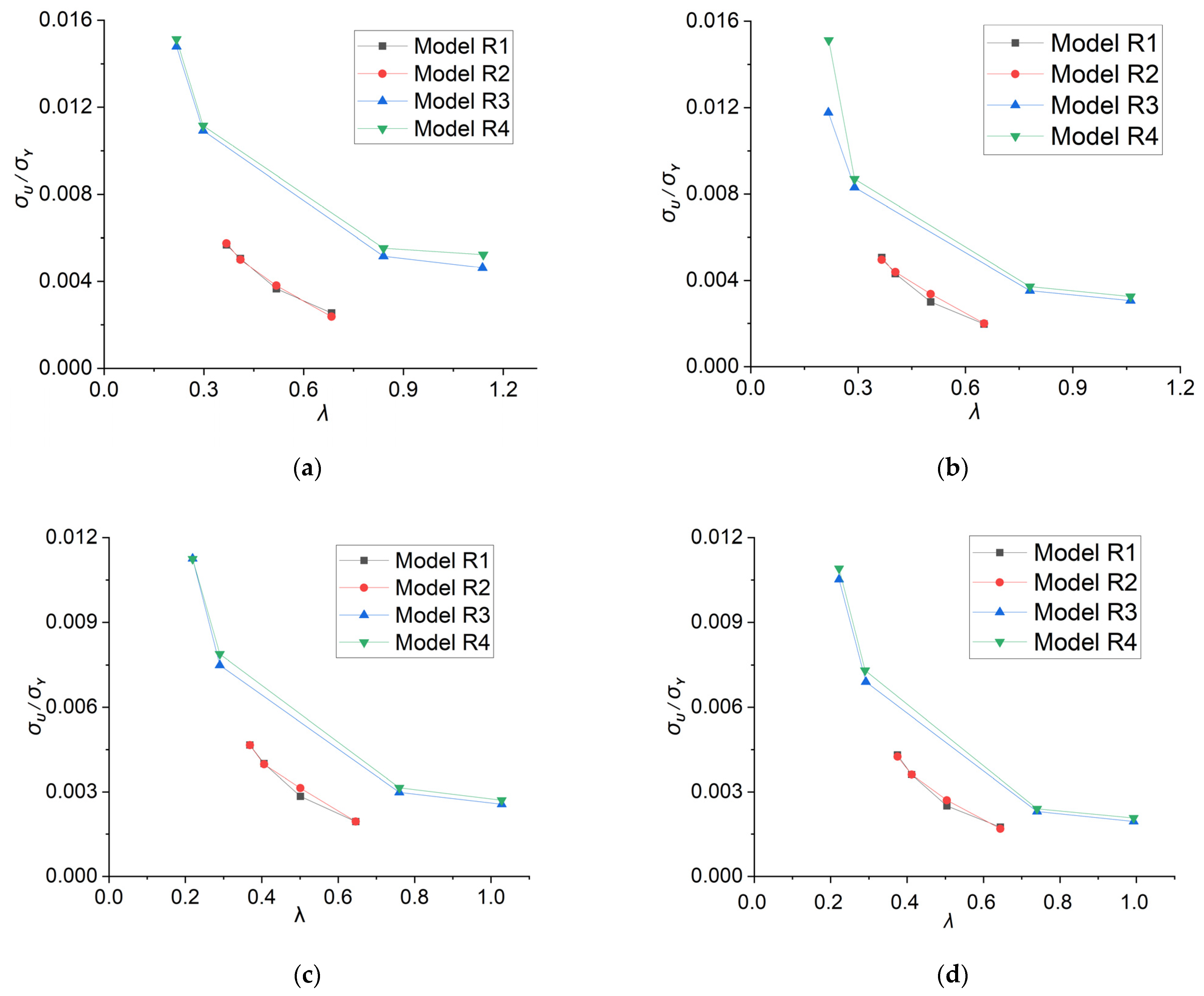
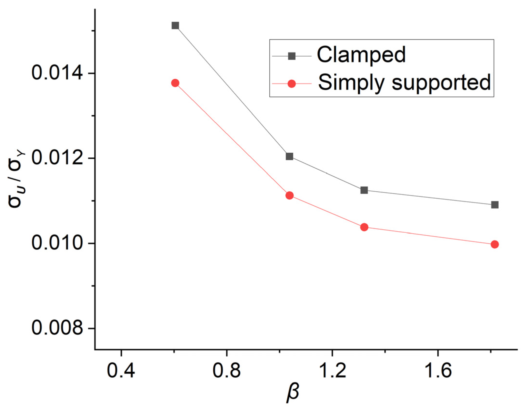
3.2.1. The Lateral Ultimate Strength of the Doubly Curved Stiffened Plates
The lateral load—central displacement curves of model R1 are shown in Figure 10. The column slenderness ratios of model R1 range from 0.368 to 0.684, while the plate slenderness ratios range from 0.605 to 1.816. The thicknesses of plates are set as 24 mm, 14 mm, 11 mm, and 8 mm, respectively, and are labeled as ‘T1’–‘T4’. Initially, the displacement of the central point increases slowly as the lateral load increases, indicating that the lateral load applied to the stiffened plate is within its loading capacity. However, once the lateral load exceeds the ultimate lateral strength, even a small increment in lateral load leads to rapid growth in the normal displacement of the central point, indicating the loss of the loading ability and collapse of the stiffened plate. Figure 10 shows that when is set constant, the lateral ultimate strengths decrease significantly for the stiffened plates with thinner plates. Models with thickness ‘T4’ exhibit the lowest lateral ultimate strength. It can be inferred that for the doubly curved stiffened plates with stronger stiffeners, the thicknesses of the plates exert a significant influence on the lateral ultimate strength.
Figure 10.
The lateral ultimate strength-displacement curve of model R1. (a) Models with stiffener ‘S1’; (b) models with stiffener ‘S2’; (c) models with stiffener ‘S3’; (d) models with stiffener ‘S4’.
The lateral ultimate strengths of models ‘R1’–‘R4’ are depicted in Figure 11. The distance between adjacent stiffeners and the plate slenderness ratios of models ‘R1’–‘R4’ are identical. Models ‘R3’ and ‘R4’ have smaller longitudinal curvature radiuses, resulting in significantly larger longitudinal curvature angles (0.415 rad for ‘R3’; 0.434 rad for ‘R4’; 0.275 rad for ‘R1’; and 0.234 rad for ‘R2’). Figure 11 shows that as the stiffeners become weaker, the lateral ultimate strengths of the doubly curved stiffened plates decrease. The relationship between lateral ultimate strength and column slenderness is inversely proportional. An interesting phenomenon is observed in cases with different plate thicknesses: the lateral bearing capacity increases significantly as the curvature angle decreases. On one hand, the curves for ‘R3’ and ‘R4’ are above those for ‘R1’ and ‘R2’. On the other hand, the lateral bearing ability of models ‘R3’ and ‘R4’ are stronger than those of models ‘R1’ and ‘R2’ even if the column slenderness ratios are significantly larger. As the curvature angle of the stiffener increases, the shapes of the stiffened plates approach spherical shells, leading to more restrained deformation of plates and stiffeners. Consequently, the lateral bearing capacities increase significantly.
Figure 11.
The lateral ultimate strengths of models R1–R4: (a) , (b) , (c) , and (d) .
In addition, the influence of low temperature has been considered in this study. Wang et al. [22] conducted a uniaxial tensile experiment on the marine steel selected for this study to investigate the effect of low-temperature conditions on the steel’s properties. The results indicate that low temperature increases the elastic modulus and yielding strength, and the ideal elastic-plastic model is still applicable under these conditions. According to the outcomes of the experiment, the elastic modulus is set as 228,000 MPa and the yielding strength is set as 373 MPa (to simulate the steel at −20 °C). Figure 12 shows the lateral strengths of model ‘R4T1S1’ under 20 °C and −20 °C. The shape difference between the two curves is not significant, while the lateral ultimate strength of the model under −20 °C is higher. And the difference between the two cases is 4.13%. As the temperature selected in the calculation is similar to the actual working conditions of ice breakers, it can be concluded that the lateral ultimate strength of the plates will increase slightly in the actual low-temperature environment. Consequently, results from models employed in this paper are conservative.
Figure 12.
The lateral ultimate strengths of model R4T1S1 (at different temperatures).
The influence of the boundary condition has also been researched. The simply supported boundary condition is set on the edges of model ‘R4S1’. The ultimate strengths under different boundary conditions are shown in Figure 13. There is a difference of around 10% between the results from models with different boundary conditions. From Figure 10, it can be concluded that the clamped boundary condition results in much larger ultimate strengths. However, since the members in the bows and stems are stronger, the results of the models with clamped boundary conditions are still referential.
Figure 13.
The lateral ultimate strengths of model ‘R4S1’ (with different boundary conditions).
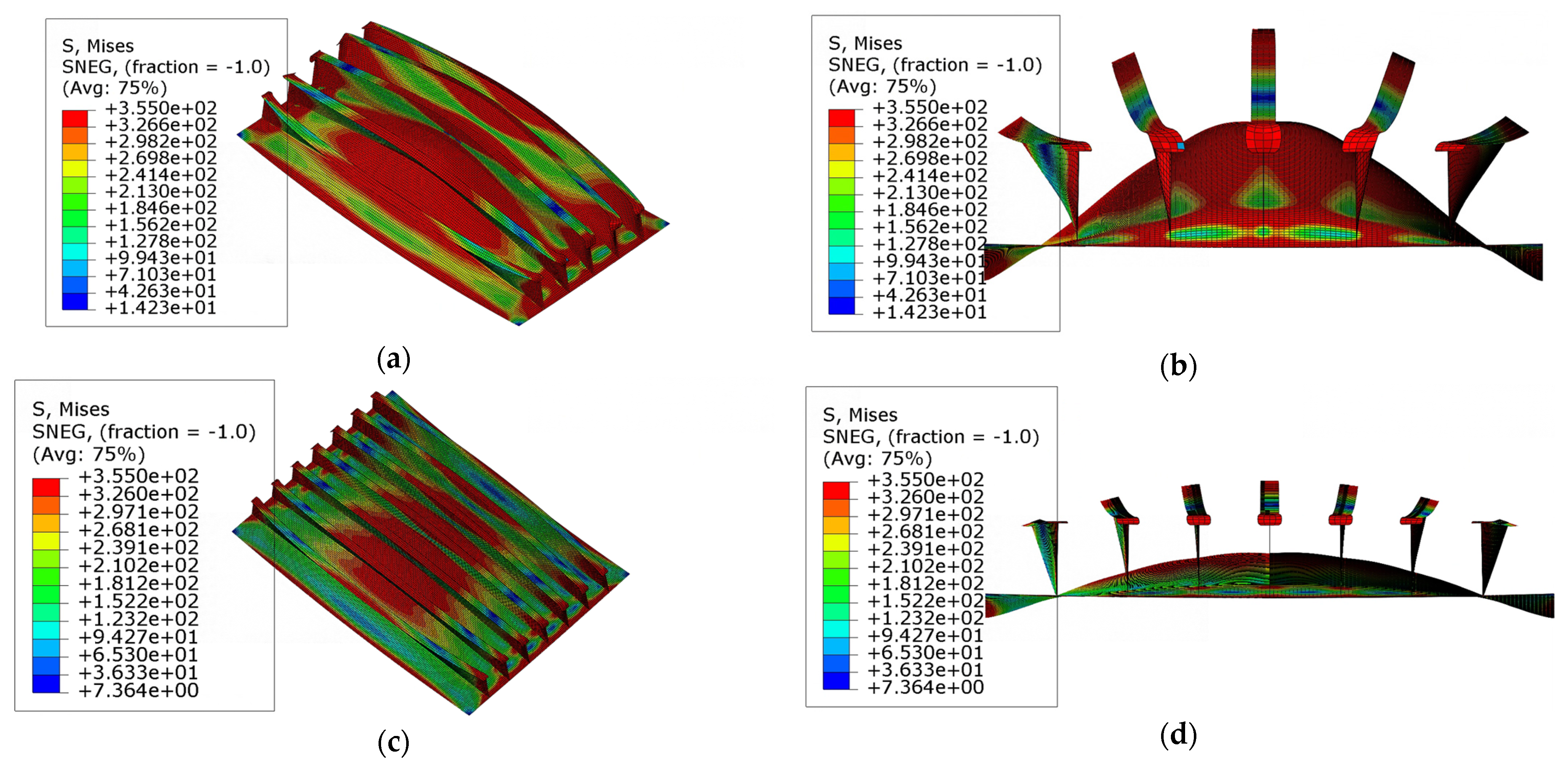
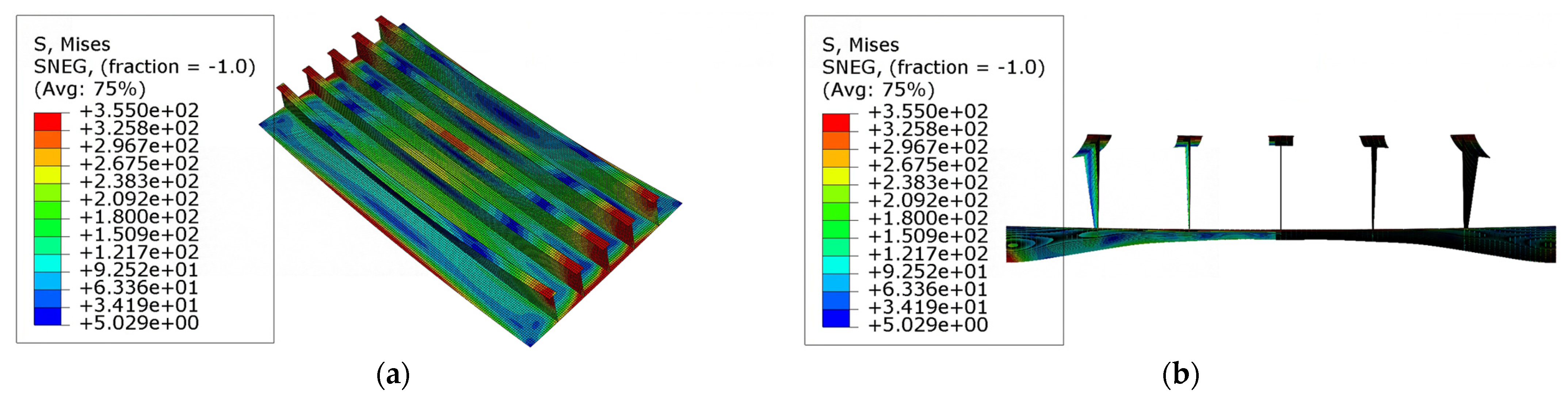
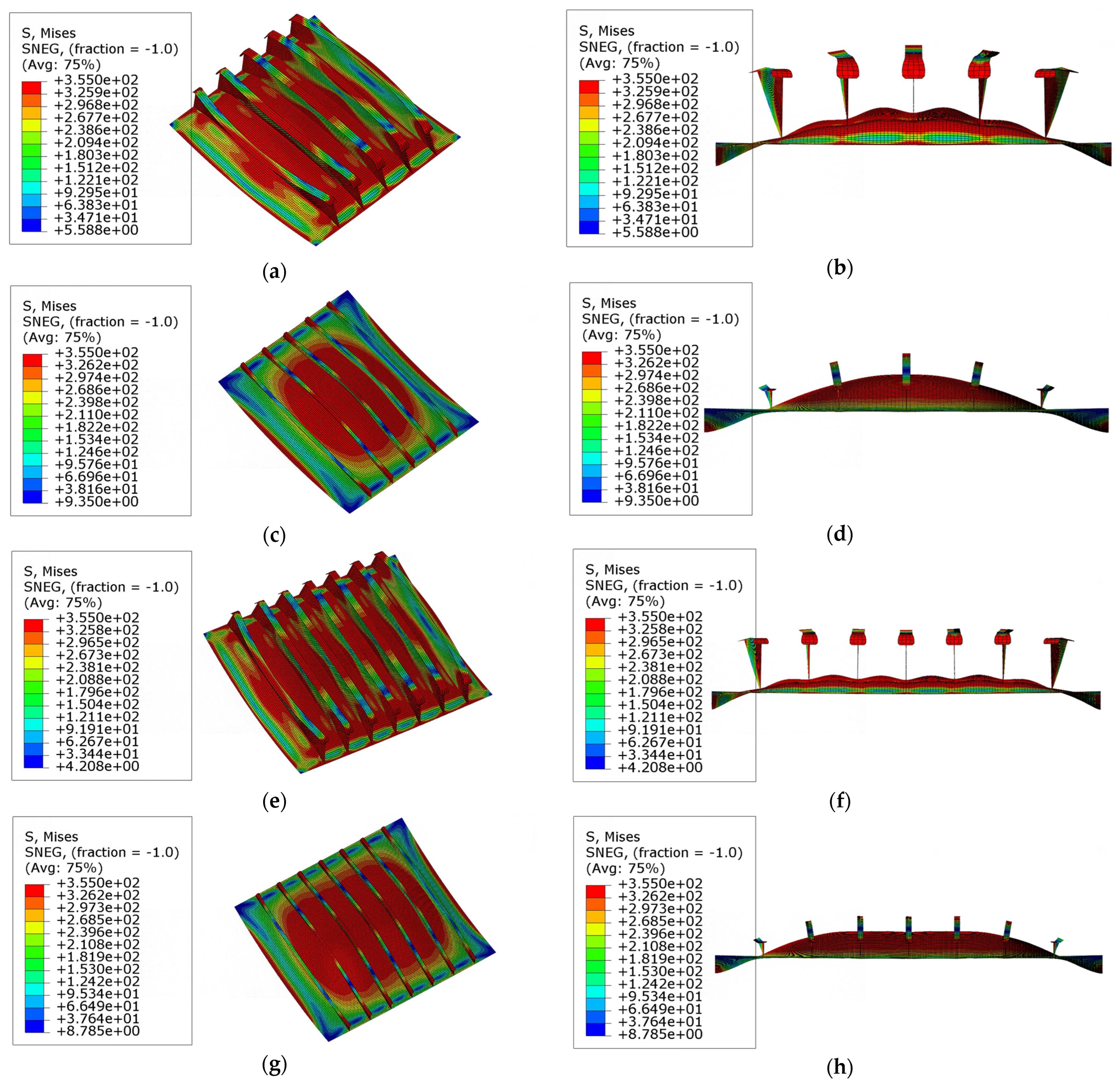
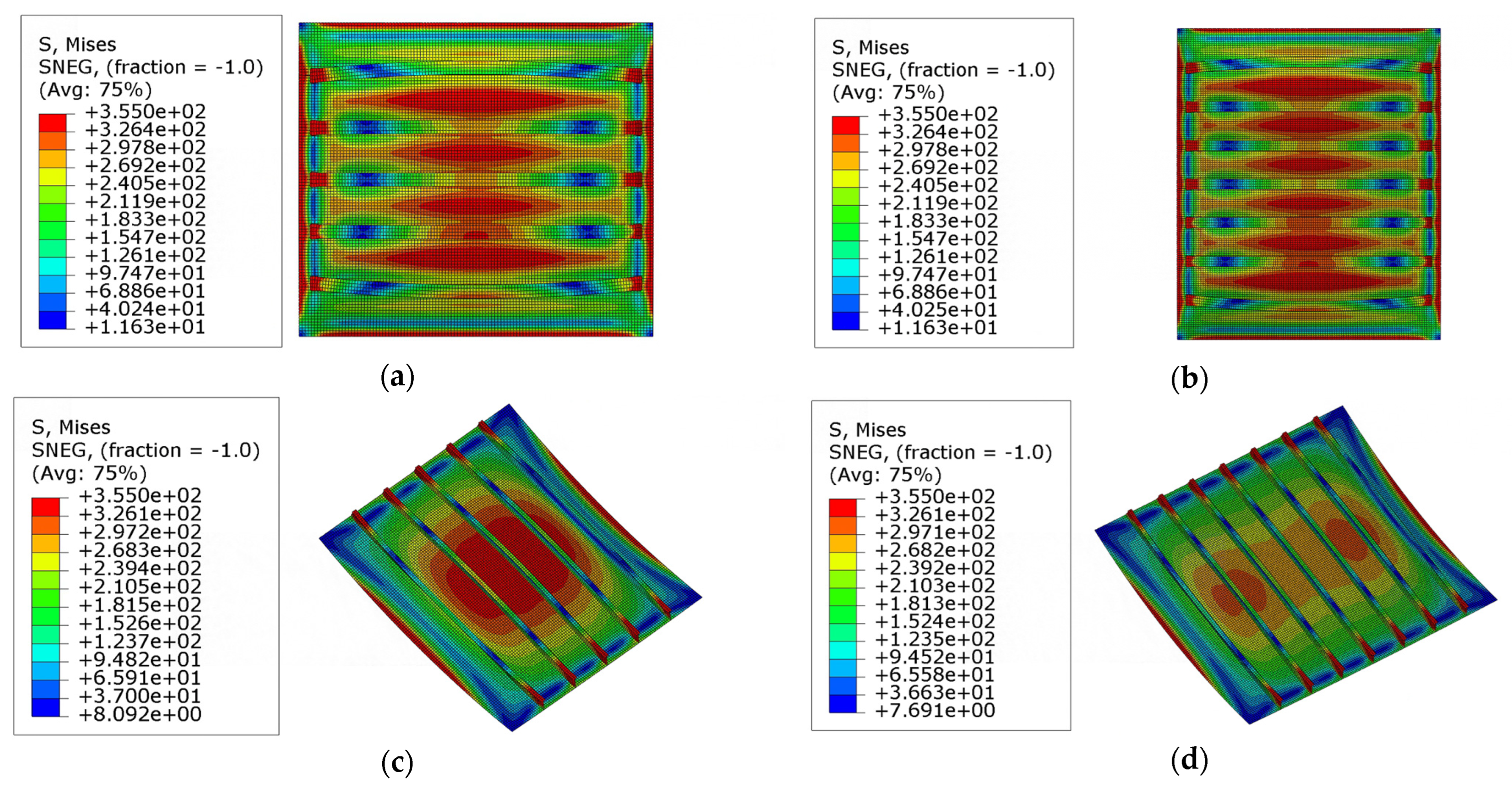
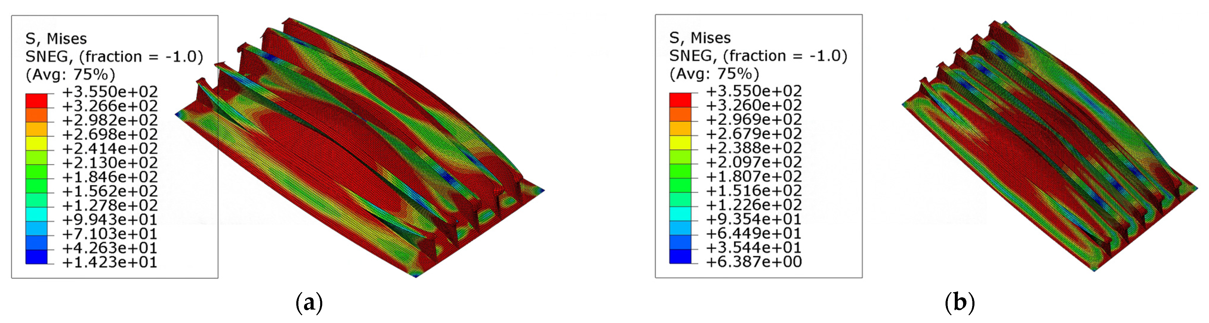
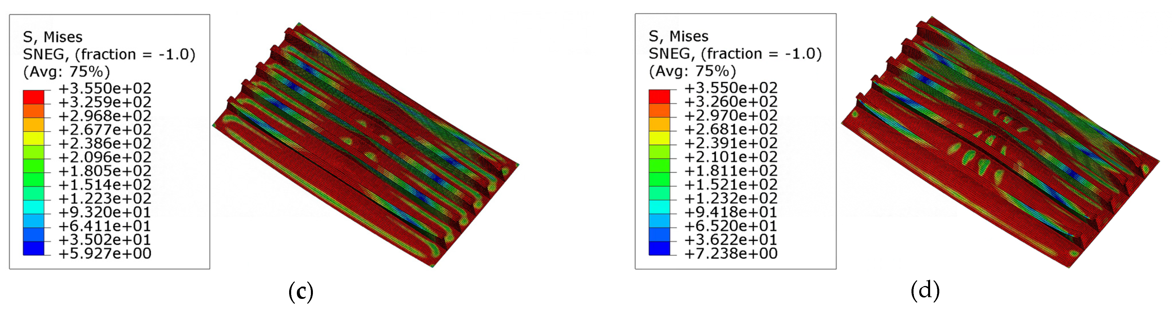
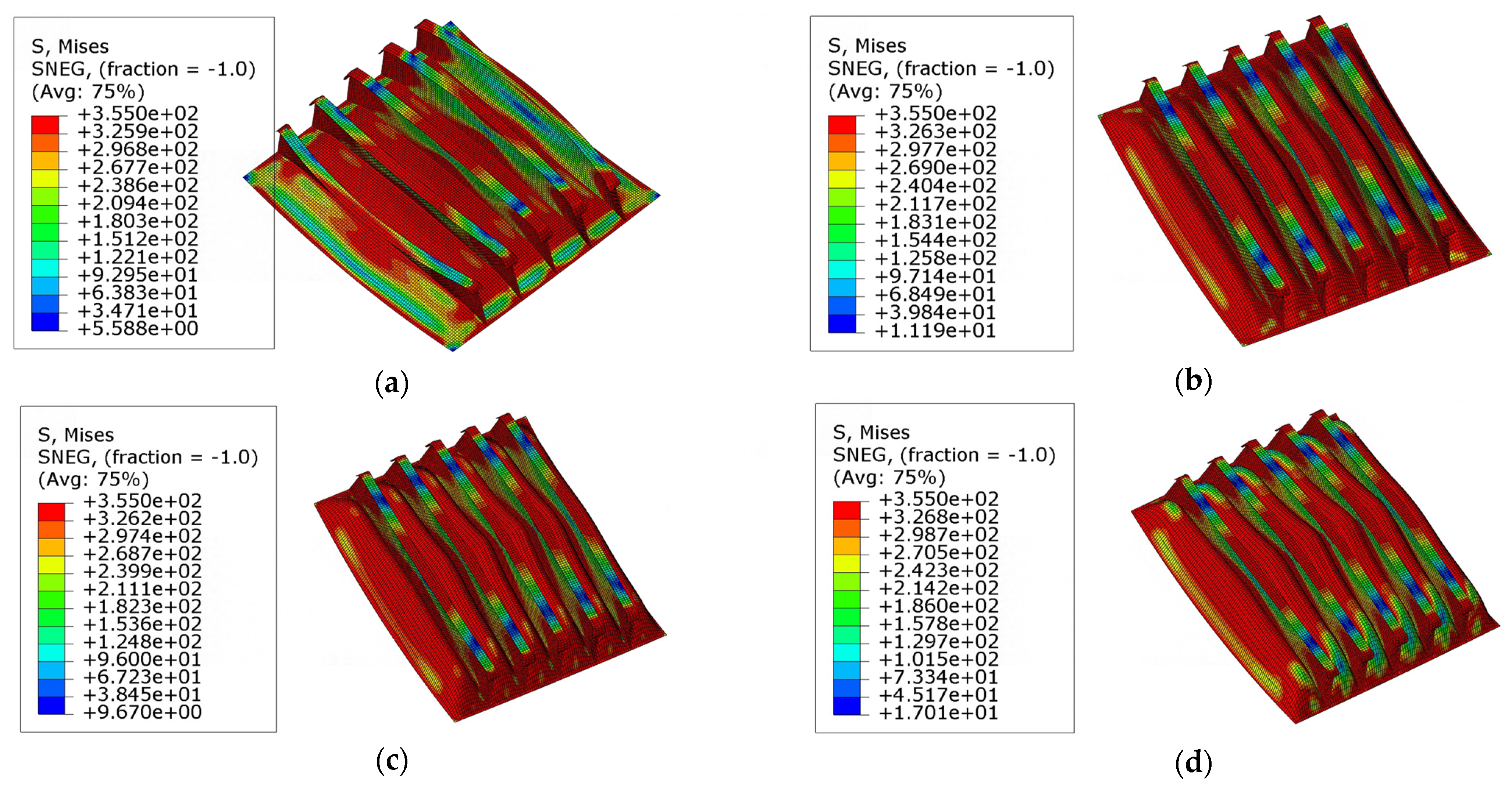
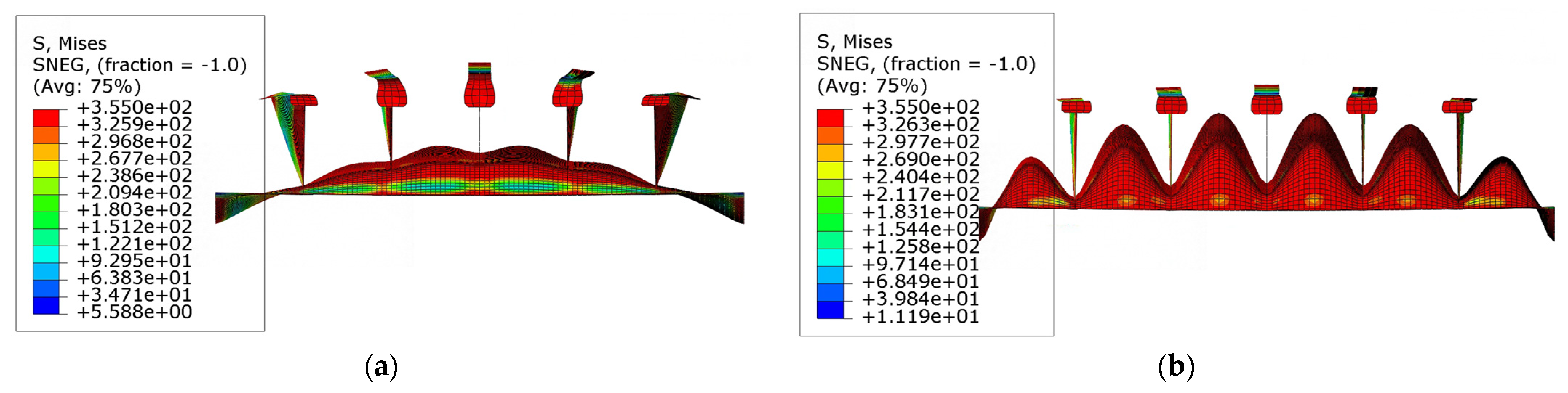
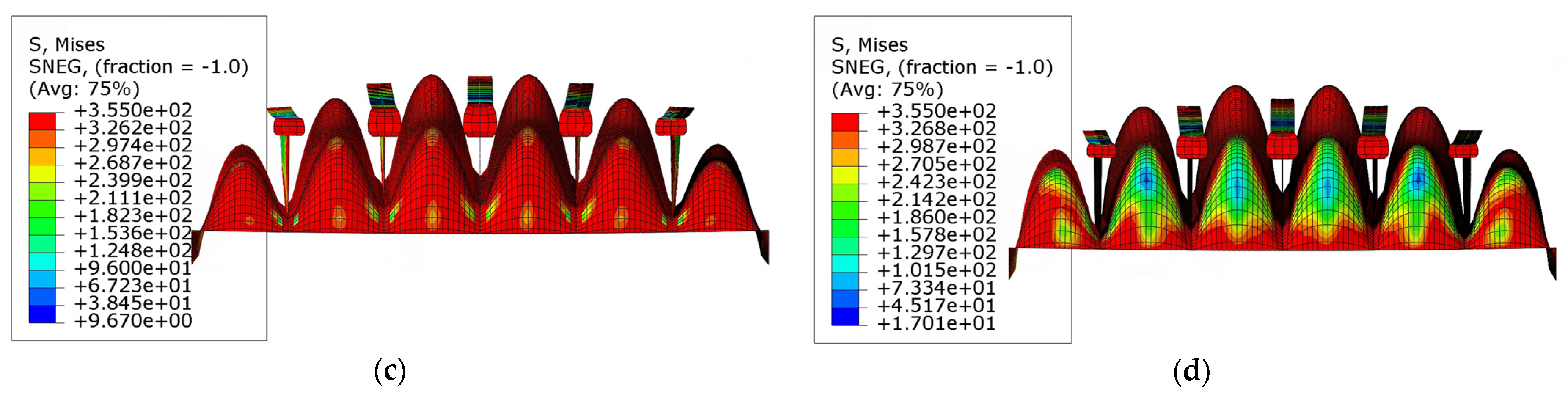
3.2.2. Typical Collapse Modes of the Doubly Curved Stiffened Plates
The stress distribution and collapse mode of models ‘R1T1S1’ and ‘R2T1S1’ are shown in Figure 14a–d. From the picture, it can be inferred that for stiffened plates with longitudinal curvature angles around 0.2, yielding and severe deformation mainly occur in the center of the plate, the upper part of the mid-span of the stiffeners, and the areas around the endings of the stiffeners. Figure 10a,b show that under lateral loading, the yielding firstly occurs around the endings of the stiffeners, and the yielding of the plates and the mid-span of the flanges occurs suddenly after the collapse around the endings of the stiffeners. Figure 15a,b demonstrate that under lateral loading, yielding first occurs around the endings of the stiffeners. The plates and mid-span of the flanges suddenly yield after the stiffeners collapse around the endings. Such a phenomenon indicates that the plate and the stiffener buckle from the peak of the curved surface simultaneously, and the corresponding collapse mode of doubly curved stiffened plates can be described as global collapse originating from the central point.
Figure 14.
The collapse modes of models R1T1S1 and R2T1S1: (a) the deformation and stress distribution at the ultimate state of model ‘R1T1S1’; (b) the front view of model ‘R1T1S1’; (c) the deformation and stress distribution at the ultimate state of model ‘R2T1S1’; (d) the front view of model ‘R2T1S1’. Scale: 10.
Figure 15.
The deformations and stress distributions of model R1T1S1 before the ultimate state: (a) the global view of model ‘R1T1S1’; (b) the front view of model ‘R1T1S1’. Scale: 10.
The collapse modes and stress distributions of the models with larger curvature angles are shown in Figure 16. In Figure 16b,f, besides global deformation, the local buckling of plates is also observed. In comparing with the phenomena shown in Figure 14, the amplitude of the global collapse decreases, whereas the area of yielding in the plate expands. Figure 17 shows the stress distribution in model ‘R3T1S1’ and model ‘R4T1S1’ before reaching the ultimate state. It is evident that the global buckling and tripping of the stiffeners occur simultaneously. These phenomena signify that the plates are subjected to stronger constraints in the normal direction, leading to increased participation of the stiffened plates in the loading capacity. In model ‘R3T1S1’ and model ‘R4T1S1’, larger curvature angles enhance the lateral bearing capacity of the stiffeners; hence, stronger normal constraints are applied to the plates. The lateral bearing capacity of the stiffened plates is finally enhanced.
Figure 16.
The collapse mode of models ‘R3’ and ‘R4’: (a) the deformation and stress distribution at the ultimate state of model ‘R3T1S1’; (b) the front view of model ‘R3T1S1’; (c) the deformation and stress distribution at the ultimate state of model ‘R3T1S3’; (d) the front view of model ‘R3T1S3’; scale: 15. (e) The deformation and stress distribution at the ultimate state of model ‘R4T1S1’; (f) the front view of model ‘R4T1S1’; (g) the deformation and stress distribution at the ultimate state of model ‘R3T1S3’; (h) the front view of model ‘R3T1S3’; scale: 15.
Figure 17.
The stress distribution before the ultimate state in models ‘R3’ and ‘R4’: (a) Model ‘R3T1S1’; (b) Model ‘R4T1S1’; (c) Model ‘R3T1S3’; (d) Model ‘R4T1S3’; scale: 15.
The collapse modes and stress distribution in models ‘R3’ and ‘R4’ with weaker stiffeners are illustrated in Figure 16c,d,g,h. In these models, the global collapse occurs during the loading process. It is because the lateral bearing capacity of stiffeners decreases as the column slenderness ratio increases, resulting in the global buckling collapse mode. As shown in Figure 17c,d, the yielding happens in the areas around the endings of the stiffeners and the center of the plates before reaching the ultimate state. This phenomenon indicates that larger curvature angles also enhance the lateral bearing capacity of the plates, and the yielding of the plates occurs earlier, which differs from the collapse mode observed in models ‘R1’ and ‘R2’.
The deformation behaviors and stress distributions of model ‘R1S1’ at the ultimate state are shown in Figure 18. It is observed that the thickness of the plate gradually decreases, leading to a more noticeable buckling of local plates. Particularly, the most severe local buckling occurs in the mid-span of the plates. As the plate slenderness ratio increases, the local buckling of the plates becomes significant, and the collapse mode converts to the combination of global buckling of the stiffened plates and the local buckling of the plates when the plate slenderness ratio becomes larger.

Figure 18.
The collapse modes and stress distribution at the ultimate state of models ‘R1S1’: (a) Model ‘R1T1S1’; (b) Model ‘R1T2S1’; (c) Model ‘R1T3S1’; (d) Model ‘R1T4S1’. Scale: 10.
The deformation behaviors and stress distributions of models ‘R3S1’ are shown in Figure 19 and Figure 20. In models with larger curvature angles along the stiffeners, the local buckling of plates becomes more significant as the plate slenderness ratio increases. As the plates become thinner, the local buckling of the plates becomes more severe, and the buckling of plate happens earlier. Consequently, the dominant collapse mode converts into the local buckling of the plates.
Figure 19.
The collapse modes and stress distribution at the ultimate state of model ‘R3S1’: (a) Model ‘R3T1S1’; (b) Model ‘R3T2S1’; (c) Model ‘R3T3S1’; (d) Model ‘R3T4S1’. Scale: 15.

Figure 20.
The front views of the collapse modes of model ‘R3S1’: (a) Model ‘R3T1S1’; (b) Model ‘R3T2S1’; (c) Model ‘R3T3S1’; (d) Model ‘R3T4S1’. Scale: 15.
The deformation behaviors and stress distribution of models with larger slenderness ratios of plates are shown in Figure 21. In contrast to the models ‘R1’ and ‘R2’ taken from an ice breaker, these models have larger plate slenderness ratios. Another collapse mode, which is different from the models discussed above, can be observed. Figure 21b,d,f show the stress distribution and deformation behaviors of these models before reaching the ultimate state. From these figures, it can be concluded that the yielding and collapse of both the plate and stiffeners occur almost simultaneously during the lateral loading process of such stiffened plates. As shown in Figure 16a–c, the buckling of plates is quite significant at the ultimate state, and the deformations of stiffeners has also become more severe.
Figure 21.
The collapse modes and stress distributions of model ‘R5’, ‘R6’, and ‘R8’: (a) ultimate state, model ‘R5T1S1’; (b) before the ultimate state, model ‘R5T1S1’ (c) ultimate state, model ‘R6T1S1’; (d) before the ultimate state, model ‘R6T1S1’; (e) ultimate state, model ‘R8T1S1’; (f) ultimate state, model ‘R8T1S1’. Scale: 10.
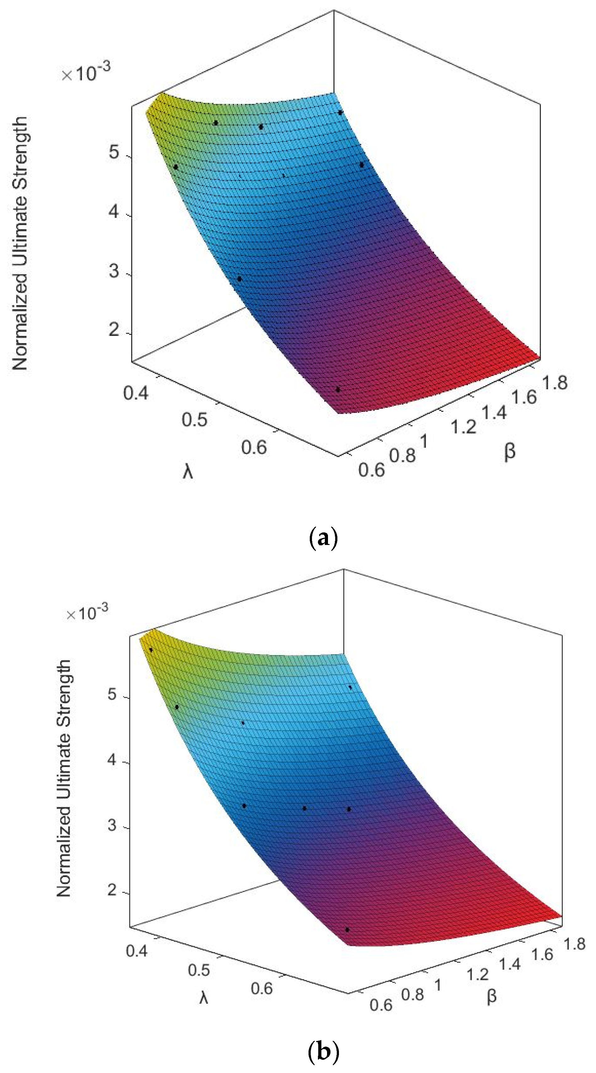
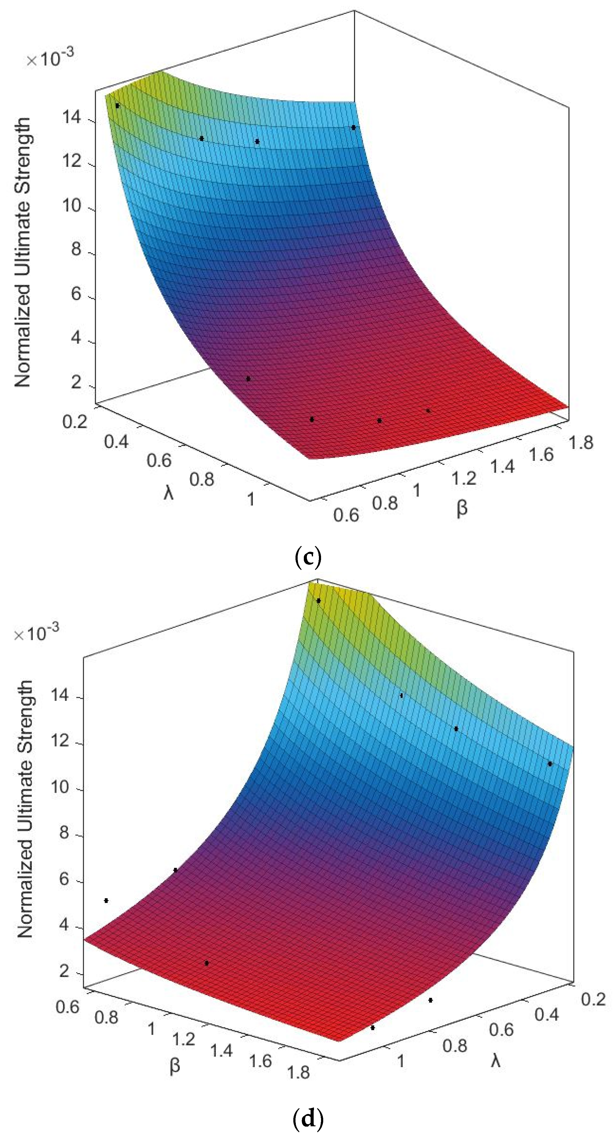
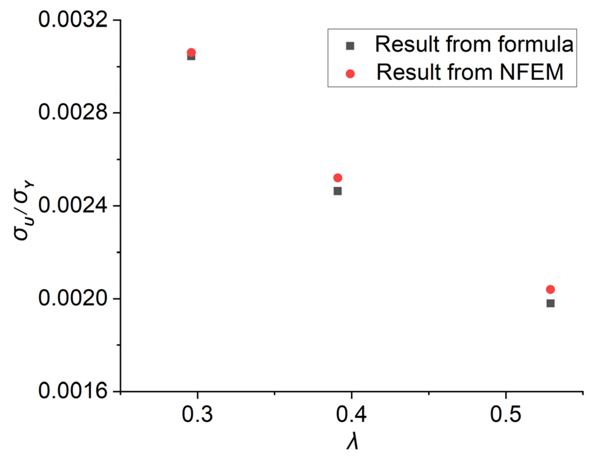
4. Empirical Formula of the Lateral Ultimate Strengths
Although the NFEM codes is a powerful tool for structural strength analysis, it requires a relatively long time to calculate and process data. Therefore, in practical structure design, it is highly desirable to use an empirical formula that contains key variables and provides a straightforward prediction for the lateral ultimate strength of stiffened plates. Before the empirical formula is presented, certain preparations have been made. First of all, the design variables have been confirmed based on experiences from structural design and analysis. Next, the variables for the formula are selected. Then, an appropriate form of the formula is constructed, considering the analyzing examples and reflecting the impact of geometrical properties on ultimate strengths. Finally, a formula is derived using the minimum mean-square error method and the NFEM results.
There are various empirical formulae for predicting the axial ultimate strength of the stiffened plates, which can provide a reasonable reference for the choice of the structure of the empirical formula for the lateral ultimate strength of the doubly curved stiffened plates. Some are only related to plate slenderness (Faulkner [23] and Paik [24]), Moreover, there are two influencing factors in other empirical formulae, including the plate slenderness and the column slenderness. As mentioned in the analysis above, both the plate’s slenderness ratio and the column’s slenderness ratio are the key influence factors of the lateral ultimate strength of the doubly curved stiffened plates.
Zhang and Khan [21] presented an empirical formula for calculating the axial compression ultimate strength of a stiffened plate, as shown in Equation (6). Based on this form, Shi [25] derived an empirical formula for evaluating the axial strength of the U-type stiffened plates, as shown in Equation (7). From the formula, we can discover that there are three coefficients selected according to the specific situation. The coefficients in such a form can signify certain characteristic of different models and load cases and it is well worth applying in other situations.
Taking the variations in the curvatures and sections of the stiffeners into consideration, a series of doubly curved plates models are established, and the lateral ultimate strength can be calculated by employing the NFEM and the results are shown in the Appendix. The influence of the curvatures on the ultimate strength is one of the main concerns. Based on these results, using the basis function fitting method and the minimum mean-square error (MMSE) technique, the corresponding ultimate strength prediction formulae in terms of slenderness ratios and and the curvature angles and are derived.
Based on the form of Equation (6), the empirical formula for predicting the lateral ultimate strength of the doubly curved stiffened is expressed as follows. To consider the effect of the curvature in longitudinal and transversal directions, the coefficients are replaced by a series of rational low-order polynomial functions. The basic form of the empirical formula is shown in Equation (8), and functions , , and are expressed in Equations (9)–(11), where the parameters , , and denote the influences of the curvature.
Comparisons with results derived from the formula and the practical NFEM are shown in Figure 22. We can find that the prediction of the formula and the NFEM results match well, with . We can also find that the lateral ultimate strengths of the doubly curved stiffened plates decrease with the increase of the parameters and from the picture; moreover, the difference distribution frequency is shown in Figure 23.

Figure 22.
Formulae predictions based on the NFEM results: (a) Model ‘R1’ R2 = 0.9894; (b) Model ‘R2’, R2 = 0.952; (c) T Model ‘R3’, R2 = 0.9679; (d) Model ‘R4’, R2 = 0.9631.
Figure 23.
Difference distribution frequency.
A stiffened plate captured from an oil tanker ( and ) is calculated using the formula and the NFEM, and the comparison between the two methods is shown in Figure 24. The values obtained from both methods are similar, and the difference between them is around 5%. And the results from the formula are slightly smaller than those from the NFEM.
Figure 24.
Comparison between the formula and the NFEM.
5. Conclusions
In this paper, the collapse modes and ultimate strengths of doubly curved stiffened plates under lateral pressure have been investigated by using the NFEM, where different groups of curvature angles have been considered and the influences of plates and stiffeners scantlings have been studied. Meanwhile, the deformation behaviors and collapse sequence of target models in lateral loading cases have been also studied. The following conclusions can be drawn:
- (1)
- The curvature angle, along the direction of stiffeners, has significant impact on the lateral ultimate strength of the doubly curved stiffened plate. The normal bearing capacity of the stiffener enhances as the curvature of stiffeners increases. As a result, a stronger constraint is applied to the plates, which strengthens the lateral bearing capacity and the ultimate strength of the doubly curved stiffeners.
- (2)
- In the lateral loading process, yielding firstly happens in the areas around the endings of the stiffeners. In most load cases, the stiffeners collapse before the plates. In actual designs, enhancing the strength of the stiffeners is a more effective way to improve the lateral loading capacity.
- (3)
- The collapse modes of the doubly curved stiffened plates can be concluded as the combination of global buckling and the local buckling of the plates. If the strength of the stiffener and the plates are similar or if the column slenderness is quite large, the global buckling will become the dominant collapse mode. The local buckling of the plates is significant in the cases with strong stiffeners and weak plates.
- (4)
- A new empirical formula Equation (4) is proposed for lateral ultimate strength prediction of doubly curved stiffeners. The proposed formula is applicable with comparing with 144 NFEM results. And the average absolute differences between the results from the formula and the NFEM is 3.7%. Over the wide range of (0–1.5) and (0.6–3) considered in this paper, the agreement between the proposed formula and numerical results is very good. Additionally, the differences between the values from the formula and the NFEM on a practical case are around 5%, which can be acceptable in engineering.
Author Contributions
Conceptualization, J.C.; methodology, J.C.; software, G.G.; validation, G.G.; writing—review and editing, G.G. and J.C.; supervision, D.W.; project administration, J.C. and D.W.; funding acquisition, J.C. and D.W. All authors have read and agreed to the published version of the manuscript.
Funding
This research was funded by NSFC (No. 52371328, No. 51809167, No. 51979163 and No. U2241266) and the Fundamental Research Funds for the Central Universities.
Data Availability Statement
Data is contained within the article.
Conflicts of Interest
The authors declare no conflict of interest.
Nomenclature
| Notations | Descriptions |
| Plate length | |
| Plate breath | |
| Thickness of attached plate | |
| Web thickness of the stiffener | |
| Web height of the stiffener | |
| Flange thickness of the stiffener | |
| Flange breadth of the stiffener | |
| The magnitude displacement of the doubly curved stiffened plate’s central point | |
| Elastic modulus | |
| The moment of inertia of the stiffener with the attached plate | |
| A | Area of transverse section of the stiffened plate |
| Gyration radius of the stiffened plate | |
| Yield stress of the material | |
| The normalized lateral ultimate stress of the ultimate state (Defined as the ratio of the lateral ultimate load-carrying capacity to the sectional area and the value of the yield stress.) | |
| The normalized axial ultimate stress of the ultimate state (Defined as the ratio of the axial ultimate load-carrying capacity to the sectional area and the value of the yield stress.) | |
| Column slenderness | |
| Plate slenderness | |
| Longitudinal curve radius of the plate | |
| Transversal curve radius of the plate | |
| Longitudinal curvature angle | |
| Transversal curvature angle | |
| Parameters in terms of curvature angles |
Appendix A. Structural Dimensions, Properties, and NFEM Solutions of the Models
| mm | mm | mm | mm | - | - | mm | mm | mm | mm | mm | MPa | MPa | - | - | - |
| 14,523 | 40,306 | 4000 | 350 | 0.00868 | 0.275 | 24 | 360 | 20 | 90 | 20 | 355 | 206,000 | 0.368 | 0.605 | 0.00568 |
| 14 | 360 | 20 | 90 | 20 | 355 | 206,000 | 0.366 | 1.038 | 0.00506 | ||||||
| 11 | 360 | 20 | 90 | 20 | 355 | 206,000 | 0.369 | 1.321 | 0.00466 | ||||||
| 8 | 360 | 20 | 90 | 20 | 355 | 206,000 | 0.375 | 1.816 | 0.00431 | ||||||
| 24 | 330 | 20 | 80 | 18 | 355 | 206,000 | 0.41 | 0.605 | 0.00504 | ||||||
| 14 | 330 | 20 | 80 | 18 | 355 | 206,000 | 0.404 | 1.038 | 0.00431 | ||||||
| 11 | 330 | 20 | 80 | 18 | 355 | 206,000 | 0.406 | 1.321 | 0.004 | ||||||
| 8 | 330 | 20 | 80 | 18 | 355 | 206,000 | 0.412 | 1.816 | 0.00361 | ||||||
| 24 | 280 | 20 | 60 | 12 | 355 | 206,000 | 0.518 | 0.605 | 0.00365 | ||||||
| 14 | 280 | 20 | 60 | 12 | 355 | 206,000 | 0.503 | 1.038 | 0.003 | ||||||
| 11 | 280 | 20 | 60 | 12 | 355 | 206,000 | 0.501 | 1.321 | 0.00284 | ||||||
| 8 | 280 | 20 | 60 | 12 | 355 | 206,000 | 0.504 | 1.816 | 0.00250 | ||||||
| 24 | 220 | 20 | 50 | 10 | 355 | 206,000 | 0.684 | 0.605 | 0.00254 | ||||||
| 14 | 220 | 20 | 50 | 10 | 355 | 206,000 | 0.652 | 1.038 | 0.00197 | ||||||
| 11 | 220 | 20 | 50 | 10 | 355 | 206,000 | 0.646 | 1.321 | 0.00195 | ||||||
| 8 | 220 | 20 | 50 | 10 | 355 | 206,000 | 0.644 | 1.816 | 0.00175 | ||||||
| 17,075 | 48,849 | 4000 | 350 | 0.00717 | 0.234 | 24 | 360 | 20 | 90 | 20 | 355 | 206,000 | 0.368 | 0.605 | 0.00575 |
| 14 | 360 | 20 | 90 | 20 | 355 | 206,000 | 0.366 | 1.038 | 0.00496 | ||||||
| 11 | 360 | 20 | 90 | 20 | 355 | 206,000 | 0.369 | 1.321 | 0.00466 | ||||||
| 8 | 360 | 20 | 90 | 20 | 355 | 206,000 | 0.375 | 1.816 | 0.00425 | ||||||
| 24 | 330 | 20 | 80 | 18 | 355 | 206,000 | 0.41 | 0.605 | 0.00499 | ||||||
| 14 | 330 | 20 | 80 | 18 | 355 | 206,000 | 0.404 | 1.038 | 0.00439 | ||||||
| 11 | 330 | 20 | 80 | 18 | 355 | 206,000 | 0.406 | 1.321 | 0.00397 | ||||||
| 8 | 330 | 20 | 80 | 18 | 355 | 206,000 | 0.412 | 1.816 | 0.00361 | ||||||
| 24 | 280 | 20 | 60 | 12 | 355 | 206,000 | 0.518 | 0.605 | 0.0038 | ||||||
| 14 | 280 | 20 | 60 | 12 | 355 | 206,000 | 0.503 | 1.038 | 0.00337 | ||||||
| 11 | 280 | 20 | 60 | 12 | 355 | 206,000 | 0.501 | 1.321 | 0.00314 | ||||||
| 8 | 280 | 20 | 60 | 12 | 355 | 206,000 | 0.504 | 1.816 | 0.00270 | ||||||
| 24 | 220 | 20 | 50 | 10 | 355 | 206,000 | 0.684 | 0.605 | 0.00237 | ||||||
| 14 | 220 | 20 | 50 | 10 | 355 | 206,000 | 0.652 | 1.038 | 0.002 | ||||||
| 11 | 220 | 20 | 50 | 10 | 355 | 206,000 | 0.646 | 1.321 | 0.00195 | ||||||
| 8 | 220 | 20 | 50 | 10 | 355 | 206,000 | 0.644 | 1.816 | 0.00169 | ||||||
| 5719 | 45,560 | 2375 | 350 | 0.00768 | 0.415 | 24 | 360 | 20 | 90 | 20 | 355 | 206,000 | 0.218 | 0.605 | 0.0148 |
| 14 | 360 | 20 | 90 | 20 | 355 | 206,000 | 0.217 | 1.038 | 0.0118 | ||||||
| 11 | 360 | 20 | 90 | 20 | 355 | 206,000 | 0.219 | 1.321 | 0.0113 | ||||||
| 8 | 360 | 20 | 90 | 20 | 355 | 206,000 | 0.222 | 1.816 | 0.0105 | ||||||
| 24 | 280 | 20 | 60 | 16 | 355 | 206,000 | 0.298 | 0.605 | 0.0109 | ||||||
| 14 | 280 | 20 | 60 | 16 | 355 | 206,000 | 0.29 | 1.038 | 0.00831 | ||||||
| 11 | 280 | 20 | 60 | 16 | 355 | 206,000 | 0.29 | 1.321 | 0.00749 | ||||||
| 8 | 280 | 20 | 60 | 16 | 355 | 206,000 | 0.292 | 1.816 | 0.00690 | ||||||
| 24 | 110 | 20 | 40 | 10 | 355 | 206,000 | 0.84 | 0.605 | 0.00515 | ||||||
| 14 | 110 | 20 | 40 | 10 | 355 | 206,000 | 0.78 | 1.038 | 0.00352 | ||||||
| 11 | 110 | 20 | 40 | 10 | 355 | 206,000 | 0.76 | 1.321 | 0.00298 | ||||||
| 8 | 110 | 20 | 40 | 10 | 355 | 206,000 | 0.74 | 1.816 | 0.00230 | ||||||
| 24 | 80 | 20 | 40 | 10 | 355 | 206,000 | 1.138 | 0.605 | 0.00462 | ||||||
| 14 | 80 | 20 | 40 | 10 | 355 | 206,000 | 1.061 | 1.038 | 0.00306 | ||||||
| 11 | 80 | 20 | 40 | 10 | 355 | 206,000 | 1.028 | 1.321 | 0.00256 | ||||||
| 8 | 80 | 20 | 40 | 10 | 355 | 206,000 | 0.993 | 1.816 | 0.00195 | ||||||
| 5475 | 54,020 | 2375 | 350 | 0.00648 | 0.434 | 24 | 360 | 20 | 90 | 20 | 355 | 206,000 | 0.218 | 0.605 | 0.0151 |
| 14 | 360 | 20 | 90 | 20 | 355 | 206,000 | 0.217 | 1.038 | 0.0120 | ||||||
| 11 | 360 | 20 | 90 | 20 | 355 | 206,000 | 0.219 | 1.321 | 0.0112 | ||||||
| 8 | 360 | 20 | 90 | 20 | 355 | 206,000 | 0.222 | 1.816 | 0.0109 | ||||||
| 24 | 280 | 20 | 60 | 16 | 355 | 206,000 | 0.298 | 0.605 | 0.01115 | ||||||
| 14 | 280 | 20 | 60 | 16 | 355 | 206,000 | 0.29 | 1.038 | 0.00869 | ||||||
| 11 | 280 | 20 | 60 | 16 | 355 | 206,000 | 0.29 | 1.321 | 0.00789 | ||||||
| 8 | 280 | 20 | 60 | 16 | 355 | 206,000 | 0.29 | 1.816 | 0.00731 | ||||||
| 24 | 110 | 20 | 40 | 10 | 355 | 206,000 | 0.84 | 0.605 | 0.00552 | ||||||
| 14 | 110 | 20 | 40 | 10 | 355 | 206,000 | 0.78 | 1.038 | 0.00372 | ||||||
| 11 | 110 | 20 | 40 | 10 | 355 | 206,000 | 0.76 | 1.321 | 0.00314 | ||||||
| 8 | 110 | 20 | 40 | 10 | 355 | 206,000 | 0.74 | 1.816 | 0.0024 | ||||||
| 24 | 80 | 20 | 40 | 10 | 355 | 206,000 | 1.14 | 0.605 | 0.00522 | ||||||
| 14 | 80 | 20 | 40 | 10 | 355 | 206,000 | 1.061 | 1.038 | 0.00326 | ||||||
| 11 | 80 | 20 | 40 | 10 | 355 | 206,000 | 1.028 | 1.321 | 0.00270 | ||||||
| 8 | 80 | 20 | 40 | 10 | 355 | 206,000 | 0.993 | 1.816 | 0.00207 | ||||||
| 74,243 | 4770 | 2400 | 650 | 0.136 | 0.0323 | 20 | 280 | 11 | 120 | 20 | 355 | 206,000 | 0.284 | 1.349 | 0.00450 |
| 24 | 280 | 11 | 120 | 20 | 355 | 206,000 | 0.298 | 1.12 | 0.00604 | ||||||
| 16 | 280 | 11 | 120 | 20 | 355 | 206,000 | 0.268 | 1.69 | 0.00316 | ||||||
| 10 | 280 | 11 | 120 | 20 | 355 | 206,000 | 0.25 | 2.7 | 0.002 | ||||||
| 20 | 320 | 11 | 60 | 15 | 355 | 206,000 | 0.305 | 1.349 | 0.00432 | ||||||
| 24 | 320 | 11 | 60 | 15 | 355 | 206,000 | 0.319 | 1.12 | 0.00613 | ||||||
| 16 | 320 | 11 | 60 | 15 | 355 | 206,000 | 0.29 | 1.69 | 0.00314 | ||||||
| 10 | 320 | 11 | 60 | 15 | 355 | 206,000 | 0.267 | 2.7 | 0.00195 | ||||||
| 20 | 210 | 11 | 60 | 15 | 355 | 206,000 | 0.475 | 1.349 | 0.00425 | ||||||
| 24 | 210 | 11 | 60 | 15 | 355 | 206,000 | 0.499 | 1.12 | 0.00550 | ||||||
| 16 | 210 | 11 | 60 | 15 | 355 | 206,000 | 0.448 | 1.69 | 0.00294 | ||||||
| 10 | 210 | 11 | 60 | 15 | 355 | 206,000 | 0.404 | 2.7 | 0.00156 | ||||||
| 20 | 120 | 11 | 40 | 10 | 355 | 206,000 | 1.01 | 1.349 | 0.00354 | ||||||
| 24 | 120 | 11 | 40 | 10 | 355 | 206,000 | 1.064 | 1.12 | 0.00456 | ||||||
| 16 | 120 | 11 | 40 | 10 | 355 | 206,000 | 0.958 | 1.69 | 0.00255 | ||||||
| 10 | 120 | 11 | 40 | 10 | 355 | 206,000 | 0.842 | 2.7 | 0.00104 | ||||||
| 13,104 | 7198 | 3044 | 675 | 0.0938 | 0.232 | 20 | 320 | 12 | 120 | 20 | 355 | 206,000 | 0.32 | 1.401 | 0.00417 |
| 16 | 320 | 12 | 120 | 20 | 355 | 206,000 | 0.308 | 1.751 | 0.00337 | ||||||
| 12 | 320 | 12 | 120 | 20 | 355 | 206,000 | 0.296 | 2.335 | 0.00230 | ||||||
| 22 | 320 | 12 | 120 | 20 | 355 | 206,000 | 0.326 | 1.274 | 0.00470 | ||||||
| 20 | 280 | 12 | 120 | 20 | 355 | 206,000 | 0.363 | 1.401 | 0.00407 | ||||||
| 16 | 280 | 12 | 120 | 20 | 355 | 206,000 | 0.349 | 1.751 | 0.00327 | ||||||
| 12 | 280 | 12 | 120 | 20 | 355 | 206,000 | 0.335 | 2.335 | 0.00224 | ||||||
| 22 | 280 | 12 | 120 | 20 | 355 | 206,000 | 0.37 | 1.274 | 0.00457 | ||||||
| 20 | 220 | 16 | 60 | 16 | 355 | 206,000 | 0.567 | 1.401 | 0.00366 | ||||||
| 16 | 220 | 16 | 60 | 16 | 355 | 206,000 | 0.537 | 1.751 | 0.00271 | ||||||
| 12 | 220 | 16 | 60 | 16 | 355 | 206,000 | 0.503 | 2.335 | 0.00168 | ||||||
| 22 | 220 | 16 | 60 | 16 | 355 | 206,000 | 0.581 | 1.274 | 0.00447 | ||||||
| 20 | 180 | 16 | 40 | 12 | 355 | 206,000 | 0.764 | 1.401 | 0.00335 | ||||||
| 16 | 180 | 16 | 40 | 12 | 355 | 206,000 | 0.724 | 1.751 | 0.00253 | ||||||
| 12 | 180 | 16 | 40 | 12 | 355 | 206,000 | 0.679 | 2.335 | 0.00167 | ||||||
| 22 | 180 | 16 | 40 | 12 | 355 | 206,000 | 0.782 | 1.274 | 0.00373 | ||||||
| 11,500 | 59,500 | 2375 | 350 | 0.00588 | 0.207 | 24 | 360 | 20 | 90 | 20 | 355 | 206,000 | 0.218 | 0.605 | 0.0124 |
| 12 | 360 | 20 | 90 | 20 | 355 | 206,000 | 0.218 | 1.21 | 0.0112 | ||||||
| 10 | 360 | 20 | 90 | 20 | 355 | 206,000 | 0.22 | 1.453 | 0.0105 | ||||||
| 6 | 360 | 20 | 90 | 20 | 355 | 206,000 | 0.227 | 2.422 | 0.0101 | ||||||
| 24 | 200 | 20 | 80 | 10 | 355 | 206,000 | 0.424 | 0.605 | 0.00584 | ||||||
| 12 | 200 | 20 | 80 | 10 | 355 | 206,000 | 0.402 | 1.21 | 0.00472 | ||||||
| 10 | 200 | 20 | 80 | 10 | 355 | 206,000 | 0.4 | 1.453 | 0.00433 | ||||||
| 6 | 200 | 20 | 80 | 10 | 355 | 206,000 | 0.403 | 2.422 | 0.00373 | ||||||
| 24 | 140 | 20 | 80 | 10 | 355 | 206,000 | 0.599 | 0.605 | 0.00369 | ||||||
| 12 | 140 | 20 | 80 | 10 | 355 | 206,000 | 0.557 | 1.21 | 0.00297 | ||||||
| 10 | 140 | 20 | 80 | 10 | 355 | 206,000 | 0.551 | 1.453 | 0.00280 | ||||||
| 6 | 140 | 20 | 80 | 10 | 355 | 206,000 | 0.548 | 2.422 | 0.00222 | ||||||
| 24 | 100 | 20 | 80 | 10 | 355 | 206,000 | 0.818 | 0.605 | 0.00273 | ||||||
| 12 | 100 | 20 | 80 | 10 | 355 | 206,000 | 0.756 | 1.21 | 0.00191 | ||||||
| 10 | 100 | 20 | 80 | 10 | 355 | 206,000 | 0.744 | 1.453 | 0.00180 | ||||||
| 6 | 100 | 20 | 80 | 10 | 355 | 206,000 | 0.73 | 2.422 | 0.00144 | ||||||
| 26,500 | 37,500 | 3200 | 800 | 0.0213 | 0.121 | 24 | 420 | 10 | 120 | 16 | 355 | 206,000 | 0.296 | 1.38 | 0.00305 |
| 20 | 420 | 10 | 120 | 16 | 355 | 206,000 | 0.283 | 1.66 | 0.00278 | ||||||
| 18 | 420 | 10 | 120 | 16 | 355 | 206,000 | 0.277 | 1.84 | 0.00263 | ||||||
| 14 | 420 | 10 | 120 | 16 | 355 | 206,000 | 0.263 | 2.37 | 0.00222 | ||||||
| 24 | 320 | 10 | 120 | 16 | 355 | 206,000 | 0.391 | 1.38 | 0.00249 | ||||||
| 20 | 320 | 10 | 120 | 16 | 355 | 206,000 | 0.373 | 1.66 | 0.00230 | ||||||
| 18 | 320 | 10 | 120 | 16 | 355 | 206,000 | 0.363 | 1.84 | 0.00217 | ||||||
| 14 | 320 | 10 | 120 | 16 | 355 | 206,000 | 0.344 | 2.37 | 0.00186 | ||||||
| 24 | 280 | 10 | 80 | 12 | 355 | 206,000 | 0.529 | 1.38 | 0.00192 | ||||||
| 20 | 280 | 10 | 80 | 12 | 355 | 206,000 | 0.501 | 1.66 | 0.00180 | ||||||
| 18 | 280 | 10 | 80 | 12 | 355 | 206,000 | 0.486 | 1.84 | 0.00174 | ||||||
| 14 | 280 | 10 | 80 | 12 | 355 | 206,000 | 0.455 | 2.37 | 0.00145 | ||||||
| 24 | 190 | 10 | 80 | 6 | 355 | 206,000 | 0.933 | 1.38 | 0.00146 | ||||||
| 20 | 190 | 10 | 80 | 6 | 355 | 206,000 | 0.883 | 1.66 | 0.00135 | ||||||
| 18 | 190 | 10 | 80 | 6 | 355 | 206,000 | 0.855 | 1.84 | 0.00126 | ||||||
| 14 | 190 | 10 | 80 | 6 | 355 | 206,000 | 0.793 | 2.37 | 0.00114 | ||||||
| 41,600 | 27,200 | 3200 | 800 | 0.0294 | 0.0769 | 24 | 420 | 10 | 120 | 16 | 355 | 20,600 | 0.296 | 1.38 | 0.00303 |
| 20 | 420 | 10 | 120 | 16 | 355 | 20,600 | 0.283 | 1.66 | 0.00270 | ||||||
| 18 | 420 | 10 | 120 | 16 | 355 | 20,600 | 0.277 | 1.84 | 0.00248 | ||||||
| 14 | 420 | 10 | 120 | 16 | 355 | 20,600 | 0.263 | 2.37 | 0.00221 | ||||||
| 24 | 320 | 10 | 120 | 16 | 355 | 206,000 | 0.391 | 1.38 | 0.00244 | ||||||
| 20 | 320 | 10 | 120 | 16 | 355 | 206,000 | 0.373 | 1.66 | 0.00229 | ||||||
| 18 | 320 | 10 | 120 | 16 | 355 | 206,000 | 0.363 | 1.84 | 0.00205 | ||||||
| 14 | 320 | 10 | 120 | 16 | 355 | 206,000 | 0.344 | 2.37 | 0.00175 | ||||||
| 24 | 280 | 10 | 80 | 12 | 355 | 206,000 | 0.529 | 1.38 | 0.00203 | ||||||
| 20 | 280 | 10 | 80 | 12 | 355 | 206,000 | 0.501 | 1.66 | 0.00174 | ||||||
| 18 | 280 | 10 | 80 | 12 | 355 | 206,000 | 0.486 | 1.84 | 0.00167 | ||||||
| 14 | 280 | 10 | 80 | 12 | 355 | 206,000 | 0.455 | 2.37 | 0.00136 | ||||||
| 24 | 190 | 10 | 80 | 6 | 355 | 206,000 | 0.933 | 1.38 | 0.00144 | ||||||
| 20 | 190 | 10 | 80 | 6 | 355 | 206,000 | 0.883 | 1.66 | 0.00130 | ||||||
| 18 | 190 | 10 | 80 | 6 | 355 | 206,000 | 0.855 | 1.84 | 0.00121 | ||||||
| 14 | 190 | 10 | 80 | 6 | 355 | 206,000 | 0.793 | 2.37 | 0.00112 |
References
- Yang, B.; Wang, D.Y. Numerical study on the dynamic response of the large containership’s bow structure under slamming pressures. Mar. Struct. 2018, 61, 524–539. [Google Scholar] [CrossRef]
- Shabani, B.; Lavroff, J.; Davis, M.R.; Holloway, D.S.; Thomas, G.A. Slam Loads and Kinematics of Wave-Piercing Catamarans During Bow Entry Events in Head Seas. J. Ship. Res. 2018, 62, 134–155. [Google Scholar] [CrossRef]
- Liu, C.; Zhang, S.L. A simple empirical formula for predicting the ultimate strength of ship plates with elastically restrained edges in axial compression. Ocean Eng. 2020, 34, 571–580. [Google Scholar] [CrossRef]
- Hayward, R.; Lehmann, E. Development of a new proof of plate capacity under combined in-plane loads. Ships Offshore Struct. 2017, 12, 174–188. [Google Scholar] [CrossRef]
- Kim, D.K.; Lim, H.L.; Yu, S.Y. A technical review on ultimate strength prediction of stiffened panels in axial compression. Ocean Eng. 2018, 170, 392–406. [Google Scholar] [CrossRef]
- Li, S.; Kim, D.K.; Benson, S. The influence of residual stress on the ultimate strength of longitudinally compressed stiffened panels. Ocean. Eng. 2021, 231, 108839. [Google Scholar] [CrossRef]
- Li, S.; Kim, D.K.; Benson, S. An adaptable algorithm to predict the load- shortening curves of stiffened panels in compression. Ships Offshore Struct. 2021, 16, 122–139. [Google Scholar] [CrossRef]
- Yao, T.; Fujikubo, M.; Varghese, B.; Yamamura, K.; Niho, O. Buckling/plastic collapse strength of wide rectangular plate under combined pressure and thrust. J. Soc. Nav. Archit. Jpn. 1997, 182, 561–570. [Google Scholar] [CrossRef] [PubMed]
- Paik, J.K.; Kim, B.J. Ultimate strength formulations for stiffened panels under combined axial load, in-plane bending and lateral pressure: A benchmark study. Thin-Walled Struct. 2002, 40, 45–83. [Google Scholar] [CrossRef]
- Ma, H.Y.; Wang, D.Y. Lateral pressure effect on the ultimate strength of the stiffened plate subjected to combined loads. Ocean Eng. 2021, 239, 109926. [Google Scholar] [CrossRef]
- Xu, M.C.; Yanagihara, D.; Fujikubo, M. Guedes Soares, C. Influence of boundary conditions on the collapse behaviour of stiffened panels under combined loads. Mar. Struct. 2013, 34, 205–225. [Google Scholar] [CrossRef]
- Li, D.Y.; Chen, Z.; Chen, X.C. Numerical investigation on the ultimate strength behaviour and assessment of continuous hull plate under combined biaxial cyclic loads and lateral pressure. Mar. Struct. 2023, 89, 103408. [Google Scholar] [CrossRef]
- Li, D.Y.; Chen, Z. Advanced empirical formulae for the ultimate strength assessment of continuous hull plate under combined biaxial compression and lateral pressure. Eng. Struct. 2023, 285, 116401. [Google Scholar] [CrossRef]
- Cui, J.J.; Wang, D.Y. Ultimate Strength of Container Ship Bilge Panels Subjected to Axial Compression Combined with Bending and Lateral Pressure. Int. J. Offshore Polar Eng. 2020, 30, 327–339. [Google Scholar] [CrossRef]
- Park, J.S.; Iijima, K.; Yao, T. Characteristics of buckling and ultimate strength and collapse behaviour of cylindrically curved plates subjected to axial compression. Adv. Mater. Res. 2008, 33–37, 1195–1200. [Google Scholar]
- Seo, J.K.; Song, C.H.; Park, J.S.; Paik, J.K. Nonlinear structural behaviour and design formulae for calculating the ultimate strength of stiffened curved plates under axial compression. Thin-Walled Struct. 2016, 107, 1–17. [Google Scholar] [CrossRef]
- Park, J.S.; Paik, J.K.; Seo, J.K. Numerical investigation and development of design formula for cylindrically curved plates on ships and offshore structures. Thin-Walled Struct. 2018, 132, 93–110. [Google Scholar] [CrossRef]
- Cho, S.; Park, H.; Kim, H.; Seo, J. Experimental and numerical investigations on the ultimate strength of curved stiffened plates. In Proceedings of the 10th International Symposium on Practical Design of Ships and Other Floating Structures, Huston, TX, USA, 1–5 October 2007. [Google Scholar]
- Paik, J.K.; Amlashi, H.; Boon, B.; Branner, K.; Caridis, P.; Das, P.; Fujikubo, M.; Huang, C.-H.; Josefson, L.; Kaeding, P.; et al. Report of specialist committee III.1 ultimate strength. In Proceedings of the18th International Ship and Offshore Structures Congress (ISSC), Rostock, Germany, 9–13 September 2012; pp. 289–352. [Google Scholar]
- Yao, T.; Fujikubo, M. Buckling and Ultimate Strength of Ship and Ship-like Floating Structure; Elsevier: Kidlington, UK, 2016; pp. 22–30. [Google Scholar]
- Zhang, S.M.; Khan, T. Buckling and ultimate capability of plates and stiffened panels in axial compression. Mar. Struct. 2009, 22, 791–808. [Google Scholar] [CrossRef]
- Wang, K.; Wu, L.; Li, Y.Z.; Qin, C. Experimental study on low temperature fatigue performance of polar icebreaking ship steel. Ocean Eng. 2020, 216, 107889. [Google Scholar] [CrossRef]
- Faulkner, D. A review of effective plating for the analysis of stiffened plating in bending and compression. J. Ship Res. 1975, 19, 1–17. [Google Scholar] [CrossRef]
- Paik, J.K.; Thayamballi, A.K.; Lee, J.M. Effect of initial deflection shape on the ultimate strength behavior of welded steel plates under Biaxial compressive loads. J. Ship Res. 2004, 48, 45–60. [Google Scholar] [CrossRef]
- Shi, G.J.; Gao, D.W. Ultimate strength of U-type stiffened panels for hatch covers used in ship cargo holds. Ships Offshore Struct. 2020, 16, 280–291. [Google Scholar] [CrossRef]
Disclaimer/Publisher’s Note: The statements, opinions and data contained in all publications are solely those of the individual author(s) and contributor(s) and not of MDPI and/or the editor(s). MDPI and/or the editor(s) disclaim responsibility for any injury to people or property resulting from any ideas, methods, instructions or products referred to in the content. |
© 2023 by the authors. Licensee MDPI, Basel, Switzerland. This article is an open access article distributed under the terms and conditions of the Creative Commons Attribution (CC BY) license (https://creativecommons.org/licenses/by/4.0/).