Article

A New Methodology-Based Sensorial System with Which to Determine the Volume of Liquid Contained in a Cylindrical Tank Subjected to Full Variations in Its Orientation

1
Grupo de Investigación Tecnológico en Energías Renovables Marinas (GIT-ERM), Escuela Técnica Superior de Ingenieros Navales, Universidad Politécnica de Madrid, Avda. Memoria 4, 28040 Madrid, Spain
2
Escuela Técnica Superior de Ingeniería Industrial de Ciudad Real, Universidad de Castilla-La Mancha, 13071 Ciudad Real, Spain
*
Author to whom correspondence should be addressed.
J. Mar. Sci. Eng. 2023, 11(12), 2316; https://doi.org/10.3390/jmse11122316
Submission received: 29 October 2023 / Revised: 26 November 2023 / Accepted: 4 December 2023 / Published: 7 December 2023
(This article belongs to the Special Issue New Trends in Offshore Renewable Energy Devices)

Abstract

:
It is necessary to determine the volume of water contained in a tank for a wide range of applications, such as the automation and monitoring of industrial operations. In the context of the marine industry, the aforementioned information plays a vital role in the effective management of submerged devices, specifically in relation to their depths and/or inclinations. In these cases, it is not feasible to quantify the volume of liquid in a tank by means of direct measurements, owing to the fact that devices can be subjected to changes in their orientation. This variation in inclination could have a variety of causes, such as the implementation of automated emersion–immersion maneuvers in a TEC or variations in depth in an AUV. Nevertheless, it can be deduced by considering the level of the tank and its geometric properties. This paper presents a new methodology-based sensorial system (composed of three capacitive sensors and an inclinometer) for accurate determination of the volume of a liquid contained within a cylindrical tank subjected to full variations in its orientation. The effectiveness of the proposed methodology-based sensorial system has been verified by the results obtained from experiments conducted on a laboratory platform, thus demonstrating the high reliability of the model experiment and the relative errors study carried out.

1. Introduction

Submersible and semi-submerged devices have, in recent times and in the particular case of the marine sector, proven to be highly valuable instruments for deep-sea applications of different natures [1,2,3,4], and the successful execution of certain tasks requires correct control of both position and orientation. This can be achieved by employing a control ballast system (CBS). The CBS operates by manipulating the weight–buoyancy forces of submerged devices, which is achieved by modifying the volume of the water in a series of tanks. The CBS is widely known for its compatibility with low fluid velocities and its ability to minimize energy consumption. However, it is important to note that the CBS is limited by its capacity to generate exclusively vertical forces. The utilization of this control system is applicable to semi-submersible platforms equipped with wind turbines [5], enabling the maintenance of a desired null orientation during the operational phase, regardless of the presence of wave and/or wind disturbances [6]; autonomous underwater vehicles (AUVs) [7,8], in order to control their depths and trim when carrying out operations such as submarine surveys, rescues [1,2], and cable laying [3]; and technologies that use the kinetic energy of water currents to generate power, usually called tidal energy converters (TECs), which employ the CBS in order to carry out automated emersion and immersion maneuvers [9,10,11].
If we focus on the performance of the automated emersion and immersion maneuvers of TECs, the use of the CBS provides these generators with the possibility of automatically changing their orientation and depth during the emersion–immersion maneuvers. This results in a great reduction in costs regarding the installation and operation and maintenance (O&M) tasks of these devices when they operate in marine environments, because it requires the use of general purpose ships rather than special high-cost vessels [12,13,14,15,16]. If the CBS control required in order to carry out the aforementioned maneuvers is to be successfully implemented, it is extremely important to obtain an accurate measurement of the volume of the liquid contained within the ballast tanks of the TEC [17]. This measurement is susceptible to alterations in both the position and orientation of the device during the execution of these maneuvers. The liquid contained inside the ballast tanks is, therefore, similarly influenced by these motions, thus leading to challenges regarding accurate quantification of the volume of water. Furthermore, in other different sectors, such as transportation, it is important to precisely establish the quantity of liquid maintained inside tanks, especially when they undergo changes in their orientations, so as to estimate and improve the operational capabilities of a variety of vehicles such as automobiles [18] or maritime vessels [19,20,21] when their orientation changes. This area of research is consequently still being actively studied.
To the best of our knowledge, there are no findings regarding sensors that are capable of directly measuring the volume of liquid in a non-null orientation tank. However, several technologies and methodologies with which to quantify the volume of liquid contained in a tank exist within the industrial sector [22]. For example, continuous-height liquid measurement [23] considers the geometric characteristics of the tank (cylinders, spheres, rectangles, squares with semi-spherical ends, etc.) and is employed to calculate the volume of the liquid contained inside the tank. The selection of a suitable level sensor is contingent on several factors, including the characteristics of the fluid (e.g., temperature, pressure, density, or dielectric properties), the specific nature of the process (e.g., foam formation, bubble generation caused by vibrating agitators, or the presence of suspended materials), and the installation conditions (e.g., whether the system is open or closed to the atmosphere and the geometric shape of the storage tank) [24,25]. Furthermore, there are a variety of level sensors, which can be categorized into three distinct measurement classifications [26,27]: (i) the displacement method, which involves the utilization of a float, commonly referred to as a buoy, which undergoes displacement in accordance with the level of the liquid. These sensors are typically used in unenclosed tanks. They can be classified as either mechanical or magnetic. Their main limitations include the potential for the movement of the float to be influenced by turbulence within the liquid [28]; (ii) hydrostatic pressure, which is produced by the vertical column of liquid contained in the tank. These sensors are typically employed in enclosed containers. They may take the form of piezo-resistive, diaphragmatic, or Bourdon tube variants [29]. One disadvantage associated with these sensors pertains to their ability to produce a proportional assessment of the liquid height on the basis of only the pressure detected at the base of the tank. This method relies on the assumption that the density of the liquid remains constant and is known; (iii) the use of the electrical properties of the liquid, which can make the sensors employed conductive [30] or capacitive [31], along with materials that have the capacity to absorb or reflect radiation, such as ultrasonic sensors [32] or radar [33].
With regard to the last measurement category, the conventional methods employed to measure levels of liquids necessitate the use of capacitive sensors [34]. A metallic rod that is submerged within the liquid and serves as an electrode is required for the process of measuring the level of the liquid. The metallic walls of the tank function as the opposite electrode. The capacitance measured has a clear relationship with the level of liquid inside the tank as a result of the influence of the dielectric constant of the liquid on the total capacitance of the system. When studying volume measurement, the capacitive-type sensor [35] is commonly employed in tanks affected by changes in orientation, as evidenced in several research works. For example, the analysis presented in [36] examines a sensor composed of two concentric cylinders constructed from insulating material. An additional cylinder separates these cylinders, resulting in an air gap between the inner and intermediate cylinders. The performance of the sensor was evaluated for various orientations of the tank. The experiments were conducted at various inclinations with angles of up to π 6 rad, resulting in an error rate of 20%. A capacitive detecting device with four electrodes affixed to the inner surfaces of a cylindrical tank was developed in [37]. The device has the capability to not only determine the quantity of liquid contained within the container but also estimate the inclination of the tank itself. The most important limitation observed in the experiments conducted concerns the inadequate measurement of angle capacities over π 6 rad. There are also specific cases in which the measurement of levels of liquids and inclinations was found to be difficult when employing the proposed methodology. The sensor configuration discussed in [38] consists of four electrodes placed on two parallel flat plates. It takes advantage of three capacitance measurements in order to determine the level of a liquid. The proposed sensor described in this study is not suitable for use in cylindrical tanks. Furthermore, as occurs with the sensor designed in the previous work, there are specific cases in which it can be complicated to use it to take measurements.
Keeping the aforementioned problems regarding the attainment of the accurate measurement of the volume of liquid contained in a tank in mind and with the intention of dealing with this limiting factor, this paper presents a new methodology-based sensorial system with which to determine the volume of liquid contained in a cylindrical tank subjected to full variations in its orientation. The main contributions made by this research to the state-of-the-art method are the following: (i) the proposed solution utilizes a sensory system consisting of three capacitive-level sensors and an inclinometer to measure the amount of liquid within a cylindrical tank. The current design has the ability to ascertain the quantity of water, despite variations in the angle with respect to the horizontal plane; (ii) calculation of the volume is conducted by analyzing the configuration of the cylindrical water wedge and categorizing cases based on the data provided by the set of four sensors; (iii) the utilization of the suggested methodology makes it possible to solve particular cases, such as those shown in previous studies [37,38]; (iv) the capacitive system described in this study detects variations in the capacitance by modifying the separation between the capacitor plates rather than changing the dielectric constant, as observed in the studies mentioned above; and (v) the proposed methodology-based sensorial system accommodates variations in the tank tilt and provides accurate volume measurement in order to ensure the ability to control the depths and/or orientations of submerged or semi-submerged CBS-based devices in a safe and reliable manner.
The remainder of the paper is organized as follows: Section 2 provides a detailed description of the proposed sensorial system based on the set of four sensors (two capacitive circular sensors, a capacitive axial sensor, and an inclinometer), with the objective of measuring the volume of ballast water in an inclined cylinder. Section 3 presents the proposed methodology-based sensorial system with which to determine the volume of liquid contained in a cylindrical tank, including the different situations associated with the distribution of a water wedge within the inclined cylinder and the redundant measurements. Section 4 defines the prototype, the arrangement of the capacitive sensors, and the equipment required. The experimental results and relative errors study are presented in Section 5. Finally, Section 6 shows our conclusions and future research work.

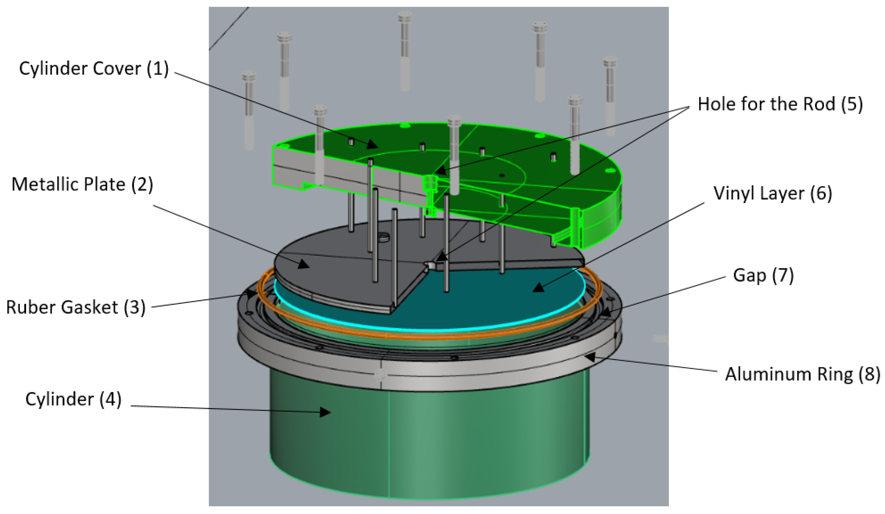
2. Description of the Proposed Capacitive Sensors

Ballast tank management is frequently employed in order to execute the movements of marine equipment. The appropriate manipulation of these ballast tanks facilitates the application of forces and/or torques to the device, thus making it possible to control their depths and/or orientations [39,40,41]. The accurate measurement of the volume of seawater contained within the device is necessary. Cylinder-shaped tanks are commonly employed owing to the need for hydrodynamic external designs. It was necessary to design the sensorial system described herein in such a way as to measure the volume of seawater in a cylindrical tank, regardless of its orientation with respect to its two main axes. This system consists of an inclinometer and three capacitive sensors. The inclinometer provides the rotational angle of the cylinder with respect to the horizontal plane. Given that the configuration of the water within the cylinder is unaffected by the remaining two angles, it may be concluded that these angles are not necessary. The experimental setup involves the use of three capacitive sensors, two of which are circular in shape and are positioned on the flat surfaces of the cylinder, and a third sensor, which is a copper rod positioned along the longitudinal axis of the cylinder, passing through its covers.
Figure 1 illustrates the Catia [42] exploded view of the proposed circular sensor for each flat face, and the most important parts are listed. The real implementation of these parts will be shown in Section 4. The metallic plate (2) located on each cover (1) is integrated within a fixed polyvinyl chloride (PVC) structure and is covered with a layer of vinyl (6), which serves as constant dielectric material and is in direct contact with the seawater. The metallic plate has a radius equivalent to that of the cylinder (4), with a central hole (5) designed to accommodate the longitudinal rod, which also traverses both the top and the bottom of the cylinder. It is necessary to include a conductor aluminum ring (8) in order to facilitate the attachment of the cover to the cylinder. The aluminum ring incorporates a gap (7) designed to accommodate a rubber gasket (3) to prevent water from getting out. This space, together with the gasket, serves the purpose of ensuring a secure and hermetic seal for the cylinder.
Water inside the tank and the aluminum rings, which are in direct contact with the seawater, makes up the desired electrical reference (zero mass) comprising the second fictitious plate of each of the capacitors. The aforementioned electrical properties of the seawater facilitate the use of this electrical reference.

Measurement of the Wet Surface

The capacitance measurement of the axial sensor makes it possible to determine the wetted length of the coated rod without the need for any preliminary calculations. However, the wet, plain surface of each of the circular capacitors, denoted as S wet , can be determined by placing a metallic plate on each of both sides of the cylindrical construction. This is determined by considering the height of the water, referred to as H wet , which makes contact with the circular metallic plate during the measurement process. In order to build a correlation between these two variables, which are illustrated in Figure 2, it is necessary to follow certain intermediary steps. The first step is that of establishing the correlation between H wet , and the angle ζ that surrounds the points of water situated on the periphery of the cylindrical surface, which is obtained as follows:
H wet ( m ) = R · 1 + cos ζ 2
where R represents the radius of the circular sector.
The wet surface, S wet ( ζ ) , can be expressed as
S wet ( ζ ) ( m 2 ) = π R 2 · 2 π ζ 2 π + R 2 · sin ζ 2 · cos ζ 2
where 0 ζ 2 π . The above equation can be simplified in the following manner:
S wet ( ζ ) ( m 2 ) = R 2 · π ζ 2 + 1 2 sin ζ
Expression (3) is then reorganized in order to obtain the following transcendental equation:
2 · π S wet ( ζ ) R 2 = ζ sin ζ
which can be solved numerically and then tabulated by means of iterative methods. The process of determining the angle ζ from S wet has been implemented as a dichotomic search, since S wet is a vector that is both ordered and increasing (the graph of the function, ζ s i n ζ , which shows that it is tonically increasing, as can be seen in Figure 3).
Finally, H wet is determined by combining expressions (1) and (4) and the wet surface, S wet , measured by the capacitance. This leads to the attainment of the following:
S wet ( m 2 ) = R 2 2 · 2 π 2 cos 1 H wet R 1 + sin 2 cos 1 H wet R 1
The relationship between the capacitance of the circular sensor and the wet surface is well-known to be proportional. In order to calibrate and determine the wet surface area of each metallic plate, it is important to know the capacitance of the capacitor under both dry and fully wet conditions. These measurements have been determined by means of experimental tests on the real platform, as described in Section 4.

3. Proposed Methodology

This section examines the different scenarios into which the water volume within a cylindrical tank of specified dimensions can be divided, regardless of its inclination angle. These cases are investigated separately owing to their different analytical requirements. The measurements are conducted under optimal circumstances, in which the sensors are assumed to be free from any potential sources of error. The definitions of the variables used are illustrated in Figure 4 and are the following:
-
φ 
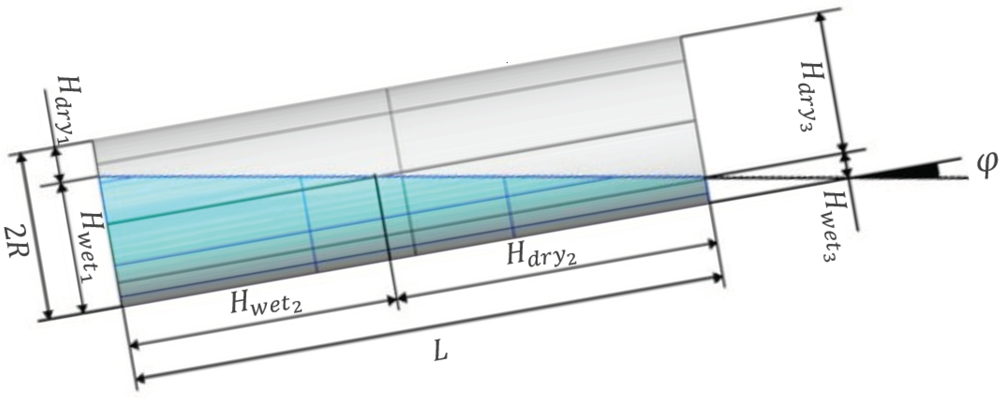
(rad): Inclination of the longitudinal axis of the cylinder with regard to the horizontal plane.
-
H wet 1 (m): Vertical distance between the water level and the first flat side of the cylinder (denoted by the subscript 1 to represent the first sensor).
-
H wet 2 (m): Measurement of the length of the axial sensor under wet conditions (denoted by the subscript 2 to represent the second sensor).
-
H wet 3 (m): The vertical position of the water level in relation to the second flat surface of the cylinder (denoted by the subscript 3 to signify the third sensor).
-
H dry 1 ( m ) = 2 R H dry 1 : The vertical distance between the dry area and the first flat side of the cylinder, where R corresponds to the radius of the cylinder.
-
H dry 2 ( m ) = L H dry 2 : The dry length of the axial sensor, where L corresponds to the length of the cylinder.
-
H dry 3 ( m ) = 2 R H dry 3 : The vertical distance between the dry area and the second flat surface of the cylinder.
-
ϵ + 0 : A mathematical term that represents the smallest expected positive angle for the inclination of the longitudinal axis.
The measurements referred to as “dry heights” or “dry lengths” are derived from the aforementioned data in an indirect manner. The following subsections deal with the different cases into which the methodology can be separated.

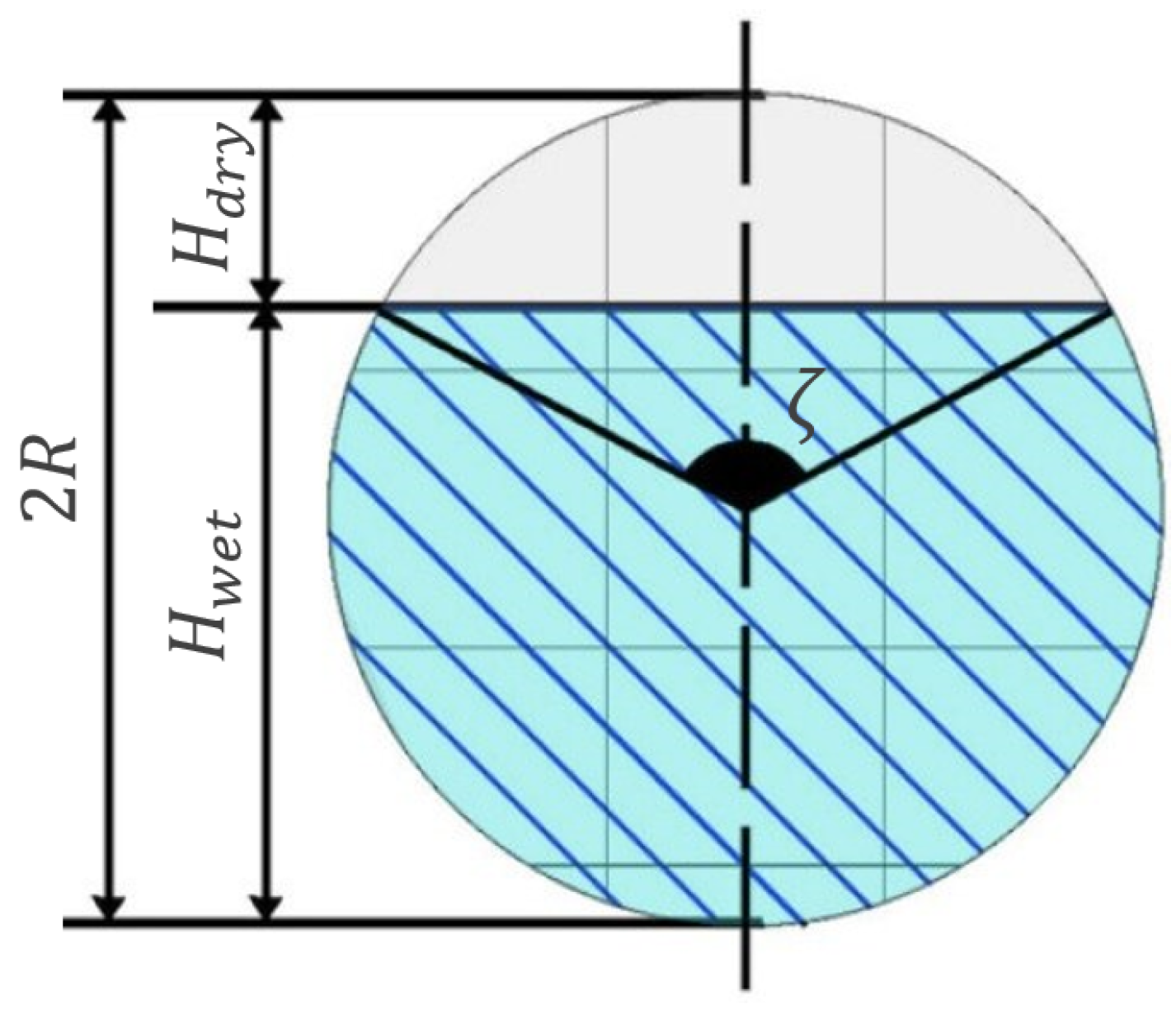
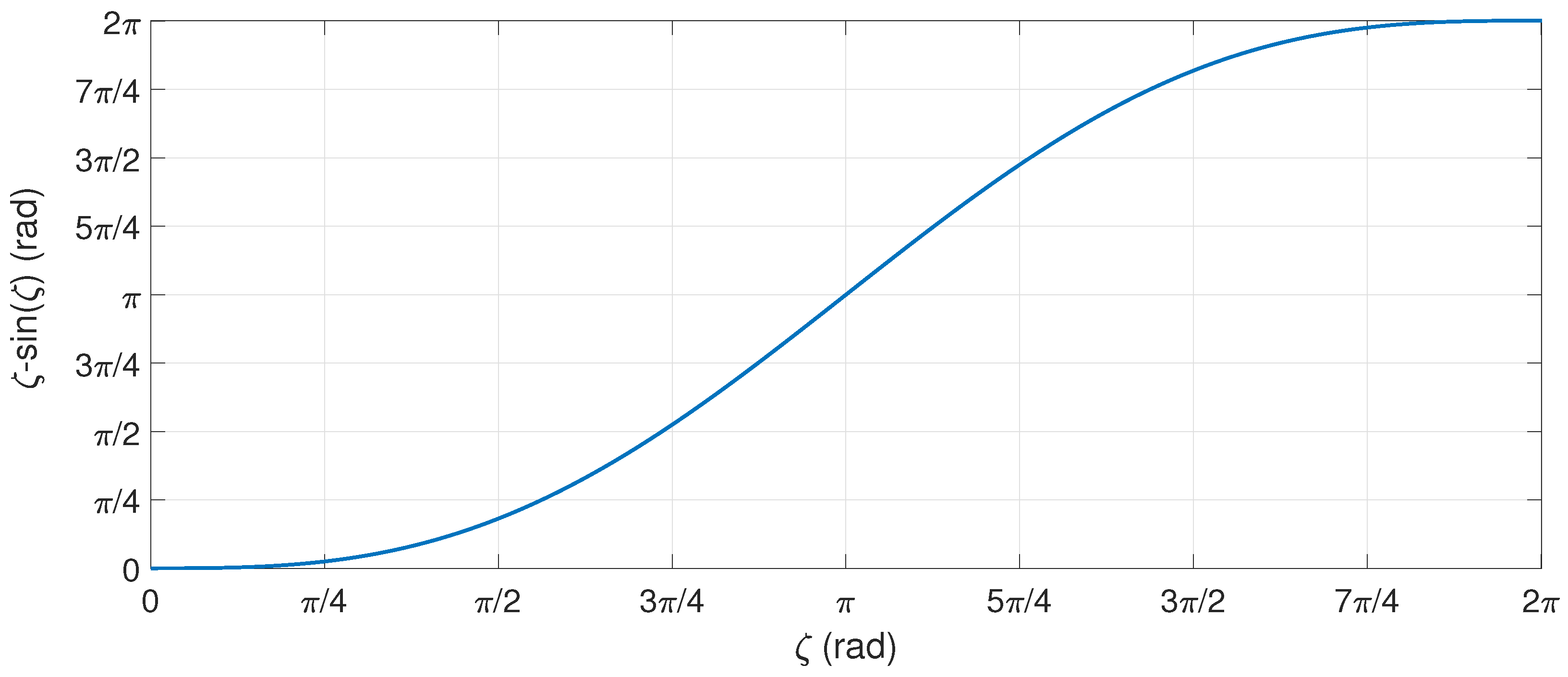
3.1. Volume of Liquid Contained in a Cylindrical Tank of Infinite Length

This case represents a cylindrical tank of radius R and an infinite length, which is rotated at an angle φ with respect to the horizontal plane. According to the hypothesis of infinite length, the most straightforward scenario in which to determine the volume of water within the cylindrical tank occurs when the water does not fully wet the flat side of the cylinder at the specified angle of inclination. This particular case is analyzed first and is illustrated in Figure 5 and Figure 6. Figure 5 shows the case in which H wet 1 < R and depicts the representation of the reference frame as an orthogonal reference defined by the orthogonal vector set { u , v , w } , which is defined only for the integral calculation of the volume. The x-axis (defined by vector u) is perpendicular to the wet plain surface of the circular capacitor and follows the longitudinal axis of the cylinder; the z-axis (defined by vector w) is vertical and points downwards; and the y-axis (defined by vector v) must form a right-handed system with respect to the x,z-axis.
The metallic plate corresponds to the initial flat side of the cylinder and is identified by the subscript 1. Furthermore, Figure 6 illustrates the case in which H wet 1 > R , and the two points of interest for the volume calculation are specified in detail below.
-
G 1 ( m ) = H wet 1 R tan φ equals the point where the axial sensor detects the water level. H wet 1 < R G 1 = 0 , although the axial sensor does not detect the water level.
-
L wet 1 ( m ) = H wet 1 tan φ equals the maximum range of water over the circular contour of the cylinder.
The volume of liquid enclosed by the cylinder can be determined by evaluating the following volume integral, which is bounded by
-
The water-free surface, which is the horizontal surface that limits the upper part of the water contained and is located between 0 and w tan φ + G 1 .
-
The cylindrical surface has an infinite length. This surface limits the bottom of the water contained and is located between R 2 w 2 and R 2 w 2 .
-
The only flat side of the cylinder is partially wet and is located between R H wet 1 and R.
V ( m 3 ) = du · dv · dw = R H wet 1 R R 2 w 2 R 2 w 2 0 w tan φ + G 1 du · dv · dw = = R H wet 1 R R 2 w 2 R 2 w 2 w tan φ + G 1 · dv · dw = = R H wet 1 R 2 R 2 w 2 · w tan φ + G 1 · dw = = G 1 w R 2 w 2 + R 2 · arcsin w R 2 R 3 3 tan φ 1 w 2 R 2 2 3 R H wet 1 R
The expression above makes it possible to determine the volume of liquid enclosed within a cylindrical tank with a wide range of inclination. A comprehensive analysis of the expression (6) necessitates the decomposition of this volumetric computation into the specific scenarios described below.

3.2. Partially Wet Flat Faces

Expression (6) is used twice, once for each of the flat sides of the cylinder when considering the water volume within a cylinder of diameter 2 R and a finite length L that partially wets both sides owing to their inclinations. The assessment of this specific case is conducted in accordance with Figure 7. The volume of water contained can be calculated using expression (6), which is achieved by subtracting the volumes, V 1 and V 3 , obtained using expression (6) and the wet heights, H wet 1 and H wet 3 , on each flat side of the cylinder.
V ( m 3 ) = V 1 V 3 = G 1 w R 2 w 2 + R 2 · arcsin w R 2 R 3 3 tan φ 1 w 2 R 2 2 3 R H wet 1 R G 3 w R 2 w 2 + R 2 · arcsin w R 2 R 3 3 tan φ 1 w 2 R 2 2 3 R H wet 3 R

3.3. A Partially Wet Flat Face

The case shown in Figure 8 can be seen as a specific circumstance of the preceding case, where H wet 3 equals zero. The volume of the associated wedge is consequently zero, V 3 = 0 .
V ( m 3 ) = V 1 V 3 = G 1 w R 2 w 2 + R 2 · arcsin w R 2 R 3 3 tan φ 1 w 2 R 2 2 3 R H wet 1 R

3.4. Horizontal Singularity

When the angle φ approaches zero and is limited to a range of ϵ φ ϵ with ϵ 0 , the tangent function can be approximated as tan φ φ . This approximation leads to badly defined divisions. The volume provided by expression (6) has a high value, V , necessitating special consideration in this particular scenario. Figure 9 depicts the singularity with H wet 1 H wet 3 > R .
The amount of water within the cylinder can be determined immediately for small angles by calculating the average of the wet surfaces S wet 1 and S wet 3 , as represented by the following expression:
V ( m 3 ) = S wet 1 + S wet 3 2 · L

3.5. One Totally Wet Face, While the Other Face Is Partially Wet

The case in question corresponds to the scenario presented in the Figure 10 and is similar to Section 3.3. The volume of liquid contained is determined by subtracting the volume occupied by air, V 3 , as determined using expression (6), from the total capacity of the cylindrical tank, V c y l = π R 2 L . The vertical extent of the entire water inside the cylinder is denoted by H. This parameter is required in order to carry out redundant measurements, as demonstrated in Section 3.7.
V ( m 3 ) = V c y l V 3 = π R 2 L G 3 w R 2 w 2 + R 2 · arcsin w R 2 R 3 3 tan φ 1 w 2 R 2 2 3 R H dry 3 R

3.6. One Totally Wet Face, While the Other Face Is Dry

An analysis of Figure 11 shows that the current case can be characterized as a vertical cylinder, because the volume of the water wedge displaced in this cylinder is equivalent to the volume of the dry wedge. This equivalence is owing to the symmetry of the tank. In this particular scenario, it is imperative to measure the water level, denoted as H wet 2 , by utilizing the axial sensor. The volume can subsequently be determined as follows:
V ( m 3 ) = S wet 1 · H wet 2

3.7. Redundant Measurements

All possible scenarios regarding how the ballast water is distributed inside the tank are covered by measuring the inclination angle of the cylinder with respect to the horizontal plane, φ , and employing the three capacitive sensors, as proposed. In certain cases, only one capacitive sensor assumes the responsibility of determining the volume of water. However, in other scenarios, the measurements obtained from all or some sensors may be redundant, which makes it possible to correct errors. These situations are summarized in Table 1, in which the water levels on either of the flat surfaces of the cylinder are represented by the variables H wet 1 and H wet 3 , while the measurement obtained from the axial sensor is represented by H wet 2 .
In the case of an angle φ < ϵ , the volume can be determined using a comparable approach, as in the case in which the angle is φ > ϵ through the permutation of H wet 1 by H wet 3 and the utilization of tan φ in the operations. The measurement range of the sensors for the specific case presented in Section 3.4 is presented in Table 2.

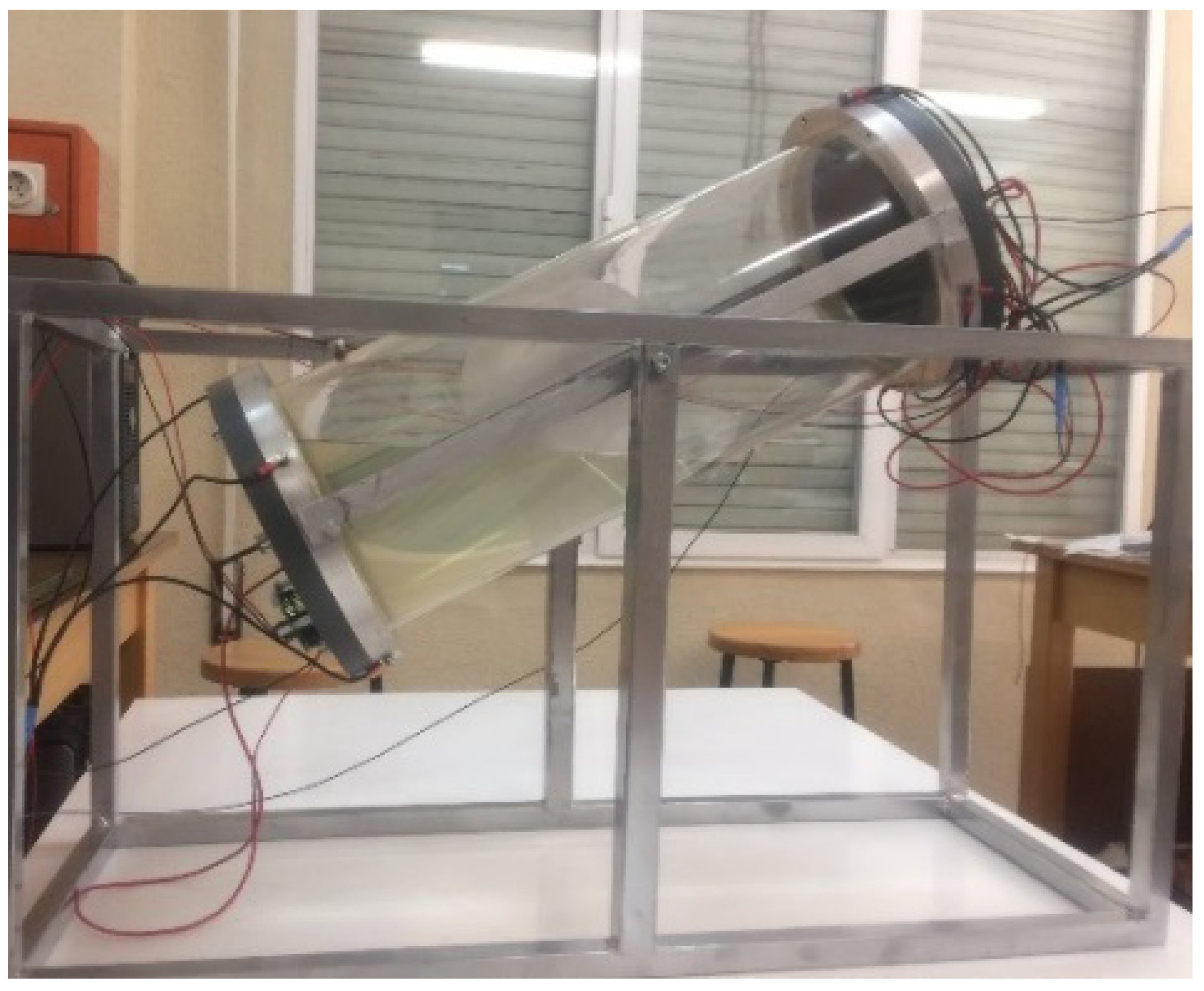
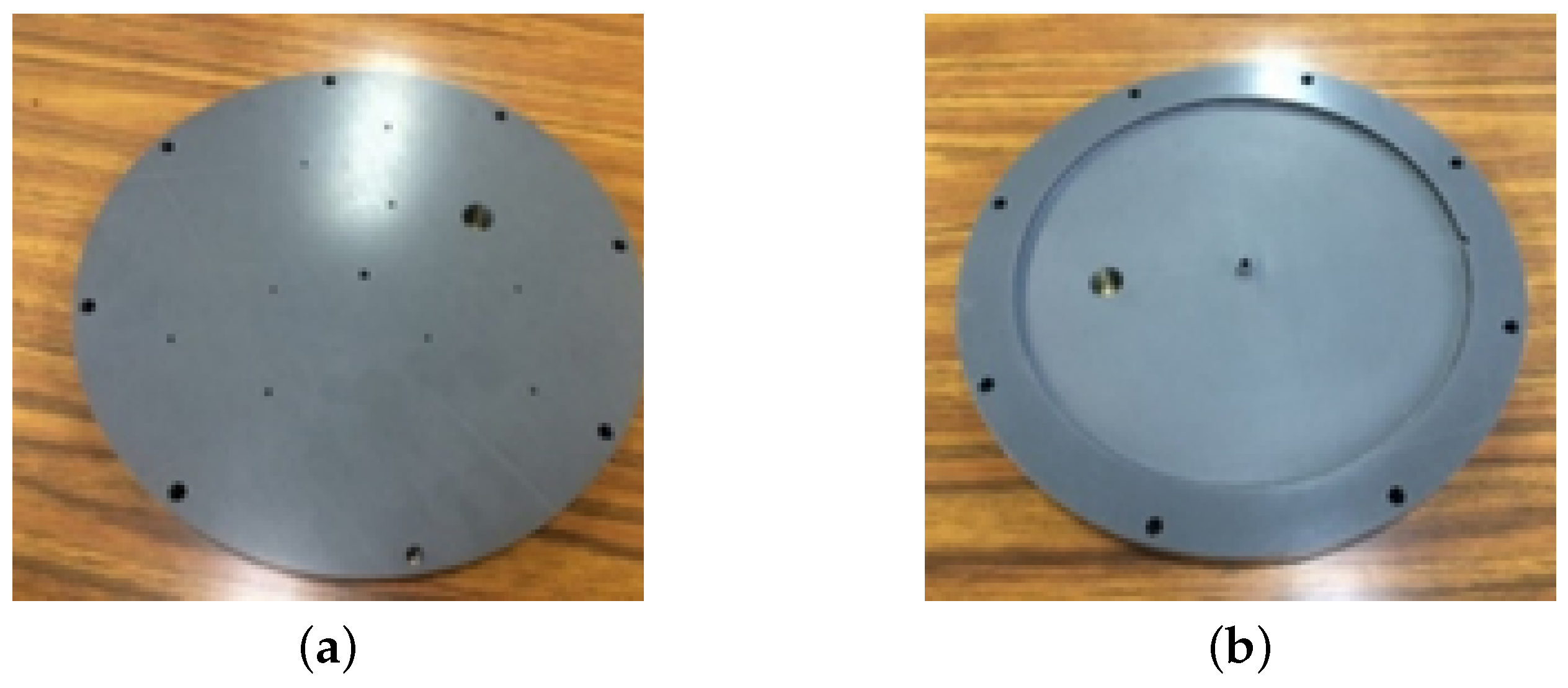
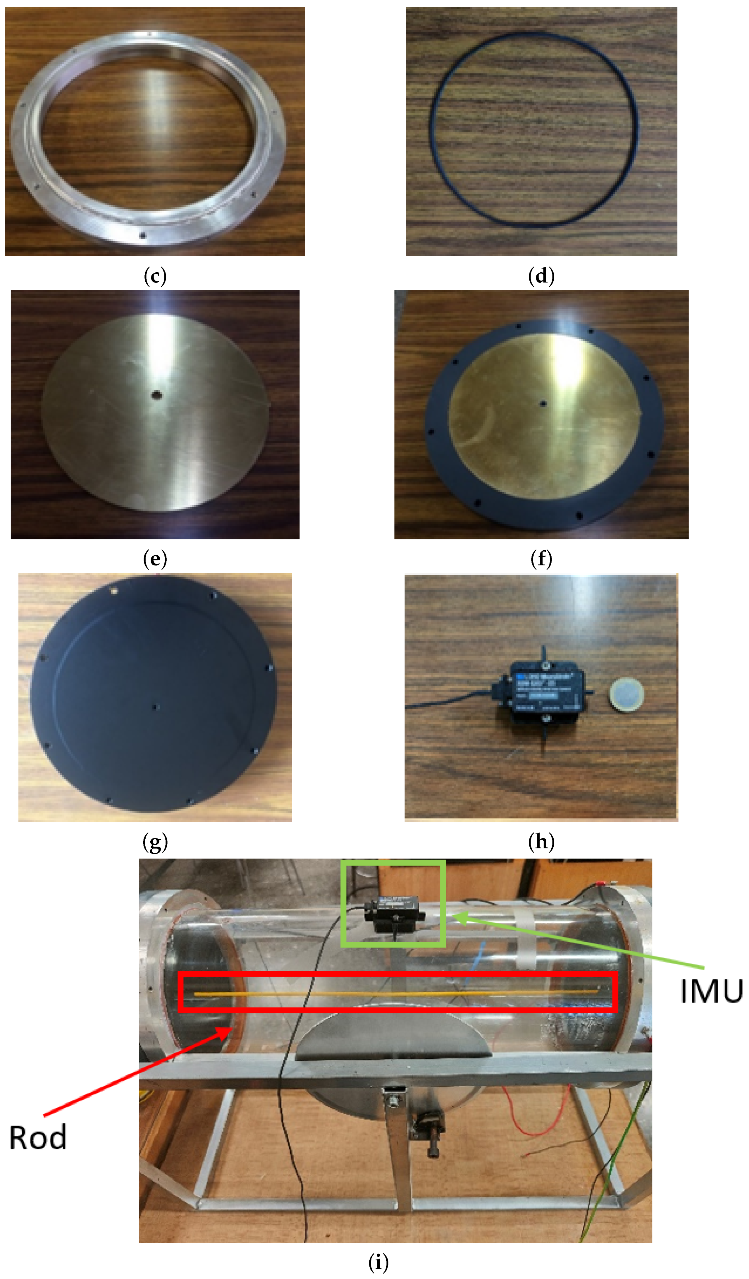
4. Description of the Experimental Setup

The experimental platform consists of a cylindrical methacrylate tank with the following characteristics: 500 mm in length with an external diameter of 200 mm and a thickness of 2.5 mm. The methacrylate cylinder is transparent, thus facilitating the observation of the amount of water and allowing an analysis of each particular case of the cylindrical tank. Figure 12 depicts the laboratory prototype designed, while Figure 13 shows the different parts of the cylinder head described in Section 2.
The cylinder is covered with two round PVC covers (see Figure 13a,b). The covers are circular, which guarantees their solid and compact attachment to the extremities of the tank. These covers have a radius of 240 mm and a thickness of 25 mm. These cylinder covers are held in place with aluminum rings (see Figure 13c) to which the PVC covers are screwed. The ring component is structurally linked by an aluminum profile, thus increasing the stability and rigidity of the prototype. The primary function of this mechanism is to effectively secure the cylinder within the chassis and, therefore, minimize any superfluous motions or vibrations that may occur during the rotation process. The ring is attached to the cylinder electrically, allowing the water to come into contact with it. The primary objective of the design of the prototype was to establish a stable and regulated setting for the quantification of water volume and the examination of the case from any inclination angle φ within the range π 2 φ π 2 (rad).
Figure 13e shows the appearance of one of the proposed metallic plates, which functions as the first capacitor plate. This consists of a brass plate with a thickness of 5 mm and a radius equal to that of the cylindrical tank. This metallic plate is securely fitted into the PVC cover (see Figure 13f). The other capacitor plate for all capacitive sensors is the aluminum frame that serves as a support for the cylindrical tank and the metal casing of the assembly of the cylinder, which act as the mass (electrical reference) of the measuring system. It should be noted that the rod must traverse the circular sensors, resulting in a small area near the center of the metallic plate that would need to be excluded. However, for the initial calculations, this area is deemed insignificant. In order to fulfill this need, a brass rod with a radius of 2 mm was, therefore, selected. Furthermore, the inner sides of each of the cylinder covers that come into contact with water are coated with vinyl (see Figure 13g). This coating serves as both a dielectric material and a layer, effectively preventing direct contact between the disc and the water. Both covers are additionally equipped with a through hole with a radius of 2 mm, which serves to accommodate the longitudinal rod used as the third sensor. The rod is encased in a thermorectile ethylene tube, serving as a dielectric material to prevent direct contact with water, similar to the brass discs. In order to quantify the rotational angle of the cylinder, an Inertial Measurement Unit (IMU) is employed (see Figure 13h), which is positioned in the upper central location on the outer side of the cylinder, as shown in Figure 13i.

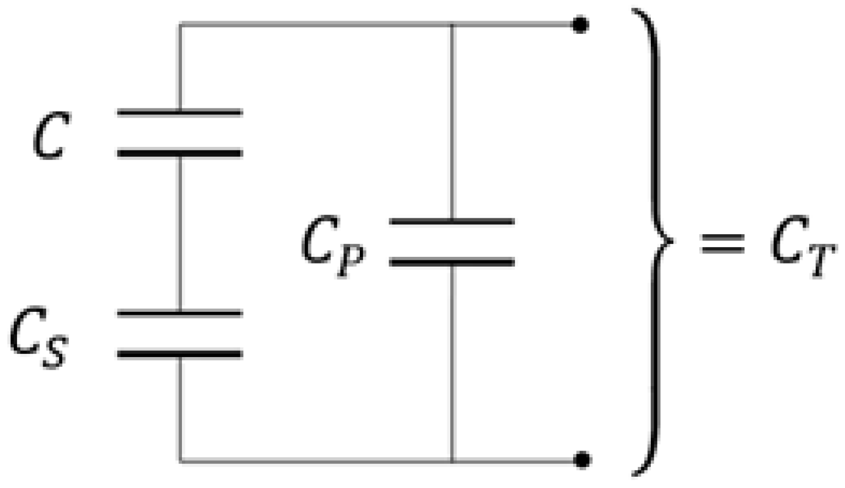
4.1. Capacitive Measurement

The experimental capacitance under wet/dry conditions was first determined experimentally by employing the traditional means of measurement consisting of analyzing the resonance frequency in a L b C circuit [43], where L b is an audio air coil calibrated with different values from 1 mH to 10 mH. The capacitances obtained after carrying out a large set of experiments with the capacitive sensors are summarized in Table 3.

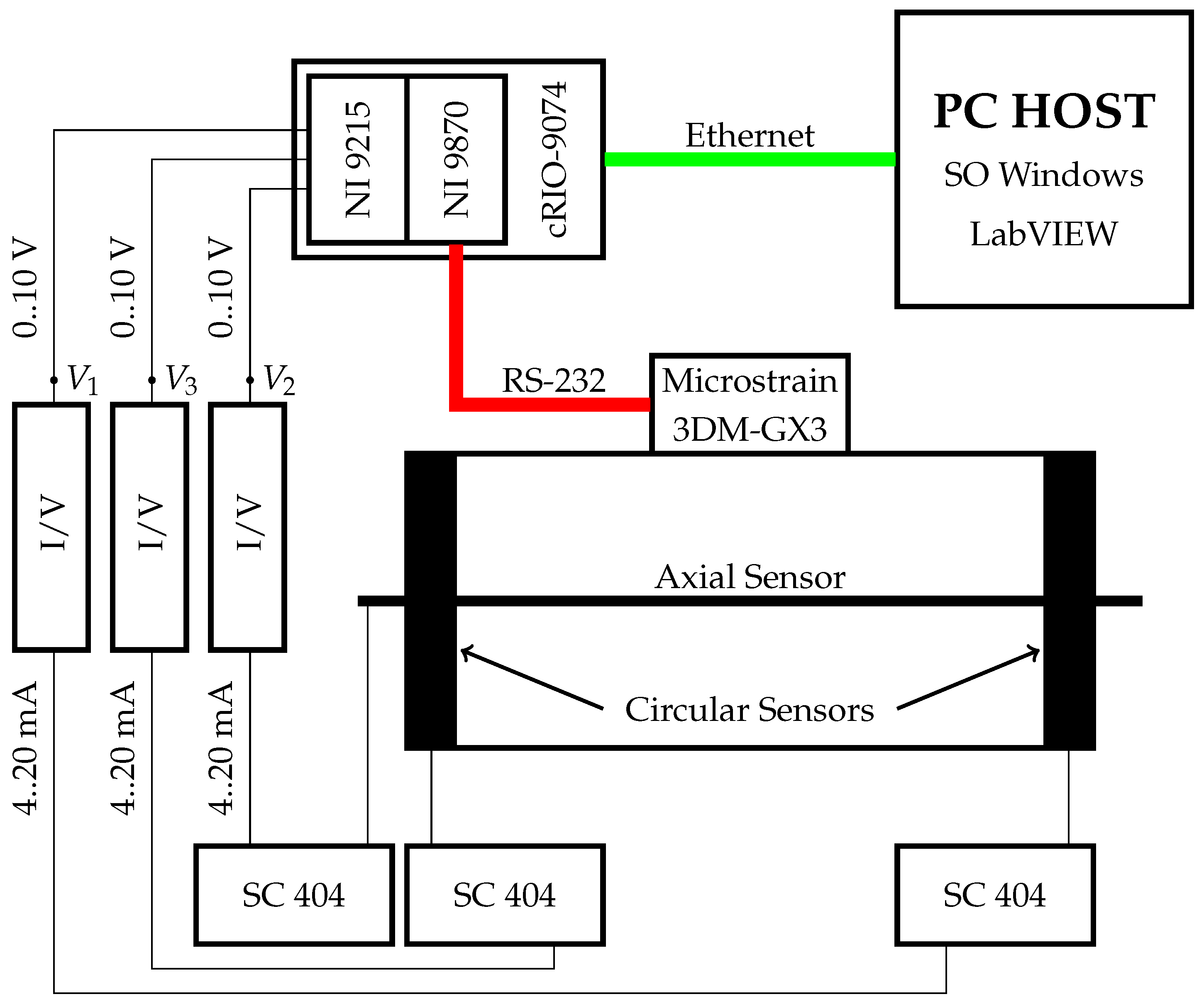
4.2. Architecture of Instrumentation

Each of the capacitive sensors is connected to a signal conditioner, the Sitron SC 404 [44], for the purpose of converting the capacitance into a 4 to 20 mA current. The Iso2-Flex I/V converter [45] converts the current signal into a voltage signal with a range of 0 to 10 V. Each of the voltage signals obtained is acquired by the NI9215 NI Voltage Module [46] provided with AD Converters, while the IMU information, Micro Strain 3DM-GX3®-25 [47], is read by the NI9870 Module [48] by means of an RS-232 connection. The IMU is powered by an Isolated Module DC-DC Converter [49]. Both modules are integrated into a cRIO-9074 [50], which is connected to a PC Host [51] using an Ethernet connection, as illustrated in Figure 14.
The Sitron SC 404 has the ability to detect and interpret many capacity ranges. The conditioner uses a gain of 1 and subgain of 1, with a read range covering 3750 pF to 5500 pF for capacitive sensors on the cover. The capacities C 1 W and C 3 W are greater than this range, and it is consequently necessary to adjust the capacitance of each sensor using the topology serial/parallel configuration, as shown in the following schematic diagram (Figure 15).
This method allows the range of the sensors to correspond with the signal conditioner span, which obtains the capacitance measurement from the capacitor set, denoted as C T . The desired variable C represents the capacitance of the circular sensor, which is determined by the following expression:
C ( nF ) = C S · C T C P C S C T + C P
The parallel capacitor, denoted as C P , has a capacitance value of 3.4 nF and serves the purpose of increasing the capacitance when the sensor is in a dry state. The serial capacitor, C S , has a capacitance value of 2.3 nF and serves to limit the capacity range of the sensor in order to correspond with that of the conditioner. The signal conditioner needs a gain of 2 and a subgain of 1 for the rod, resulting in a capacitance range spanning from 900 pF to 1500 pF. In this case, it is necessary to increase the capacity of the rod with a parallel capacitor of 800 pF.

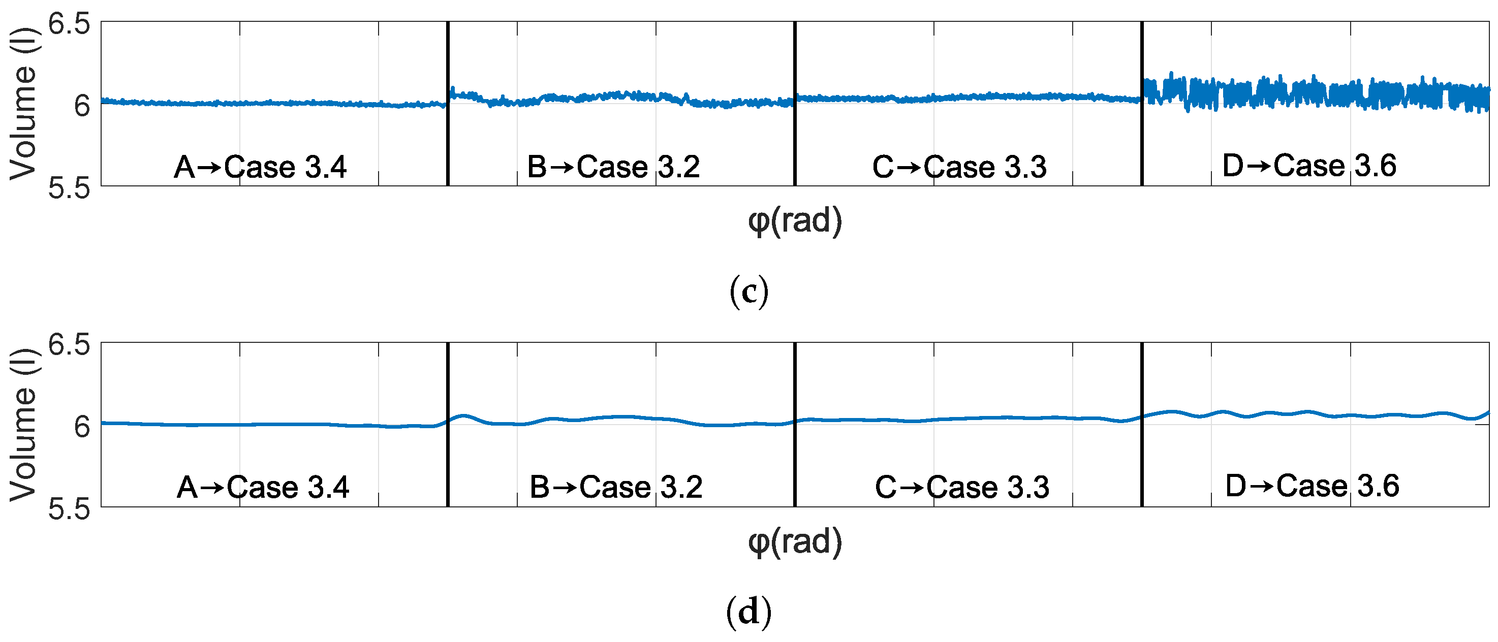
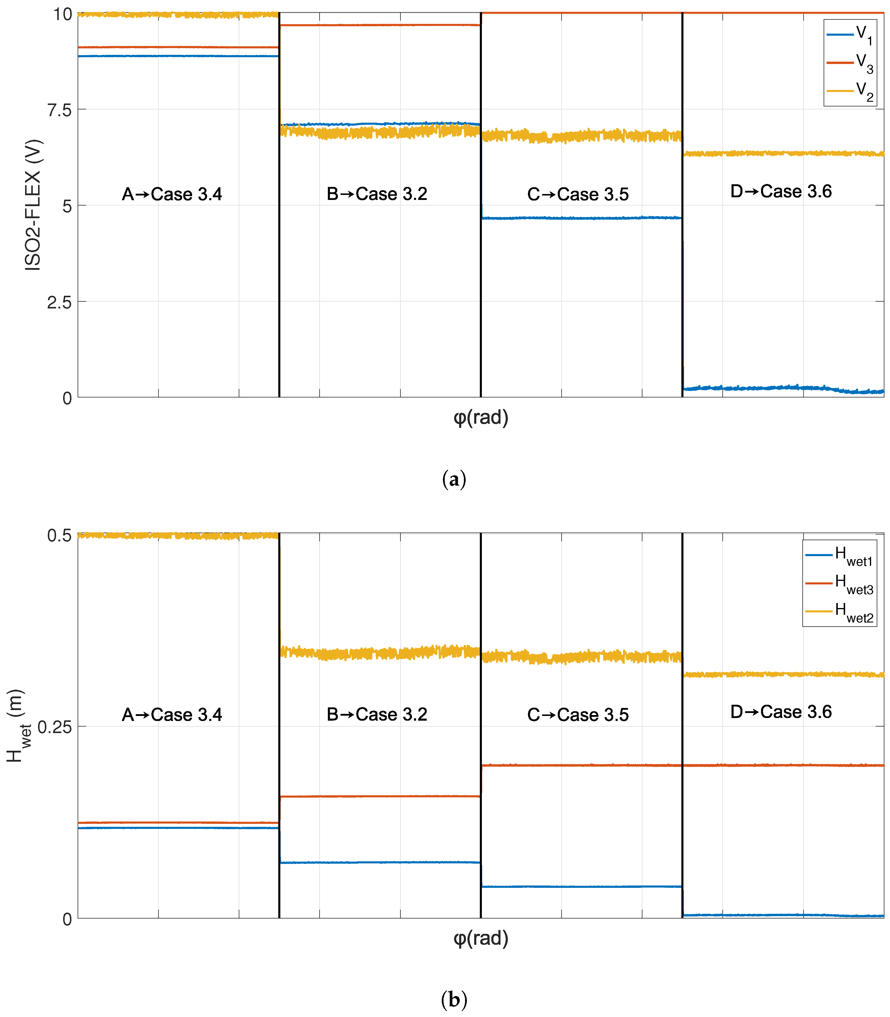
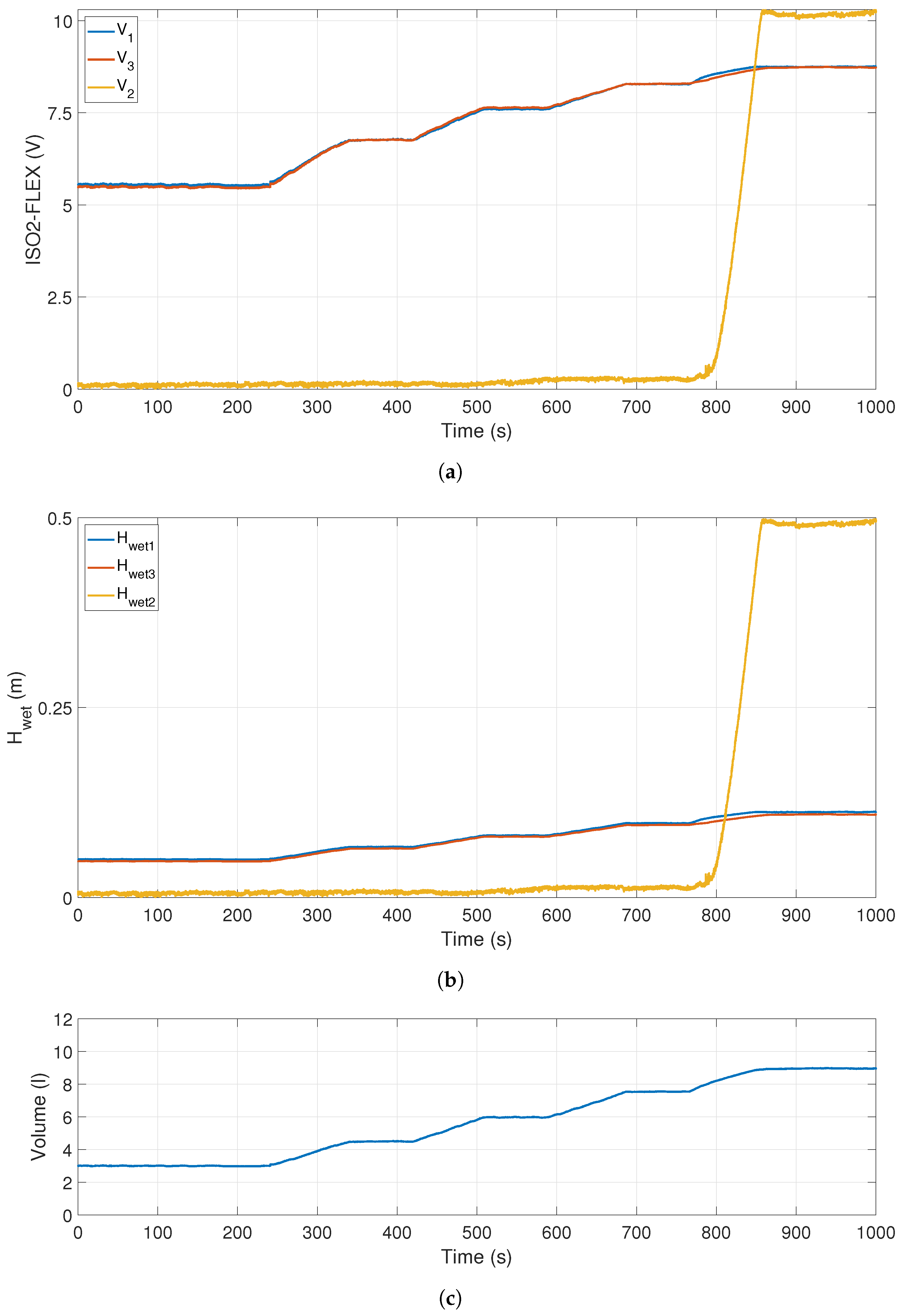
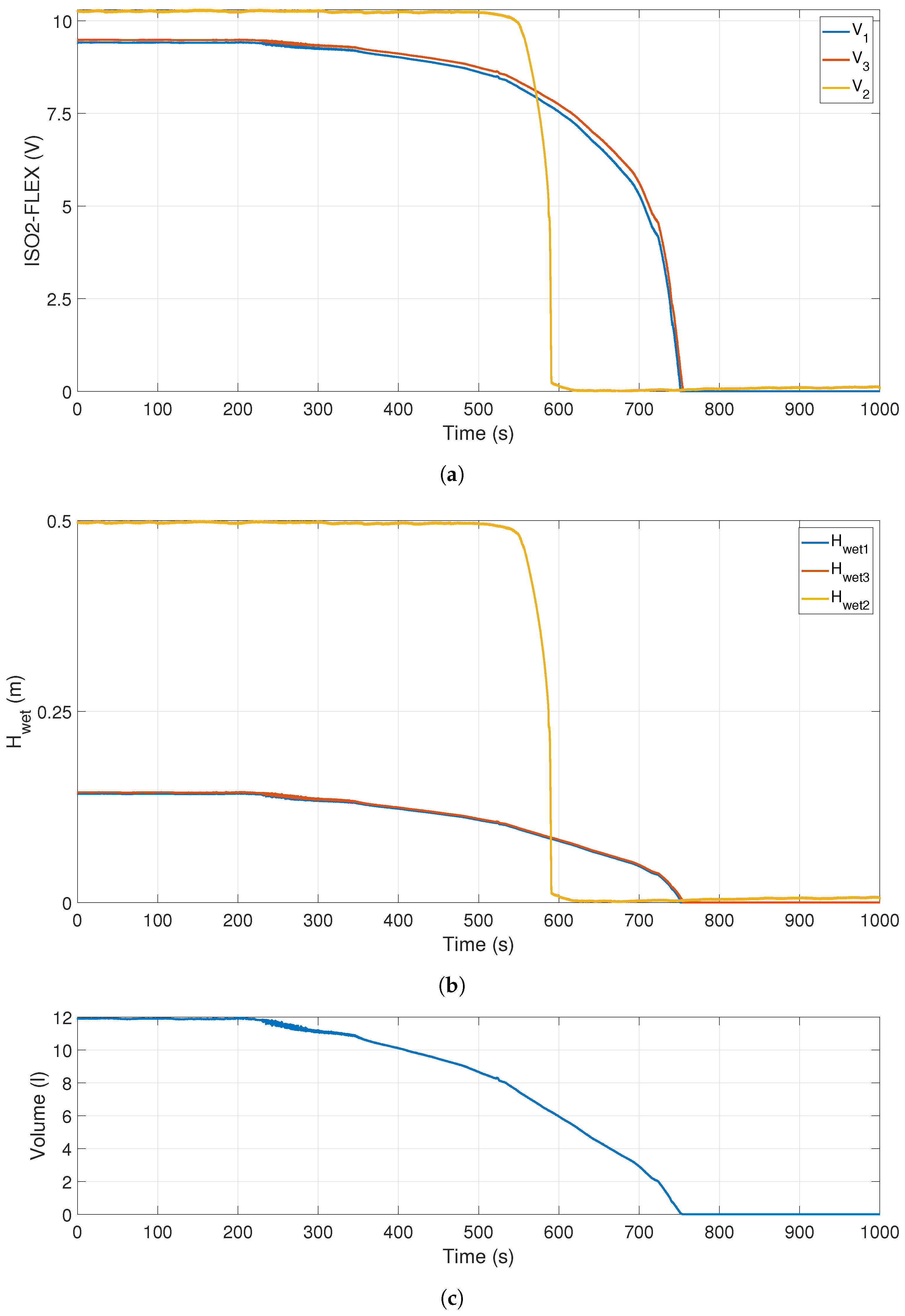
5. Experimental Results
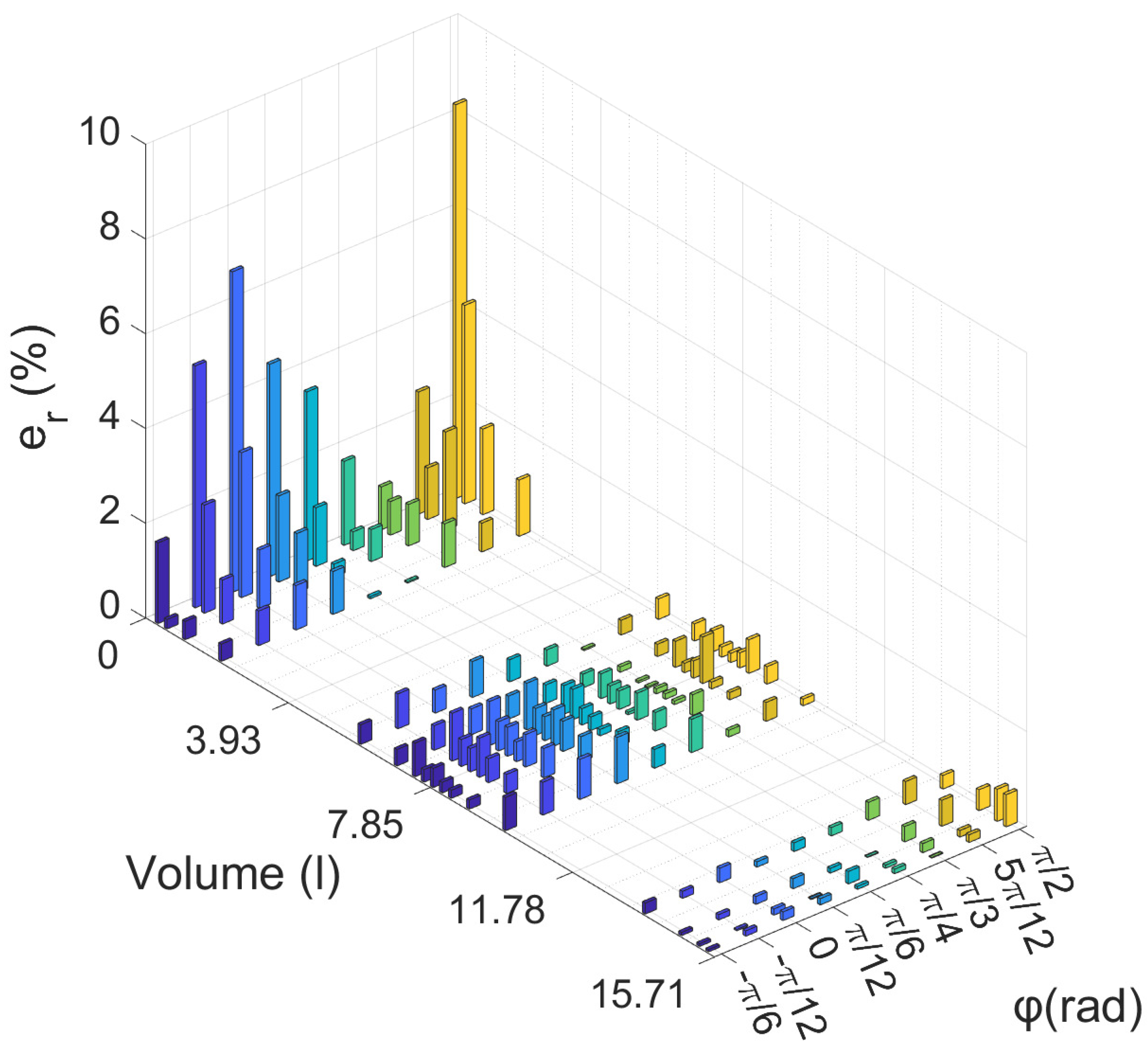
This section presents a selected set of results showing the voltage output data of the converter V/I, the corresponding wet height values, H w e t , for each of the sensors, and the resulting volume calculated during the experimental tests using the proposed methodology. The figures presented show the unprocessed data obtained from the experiments in order to determine the volume of water inside the prototype at different angles or at the same angle while it was being filled or emptied. The data have not undergone any form of processing or filtration, except when indicated.
Figure 16 and Figure 17 represent the signals obtained when the volume of water contained remained constant at 6 and 10 l, respectively, while assuming different orientations. The graphs are divided into four different parts, each of which represents the value of a specific angle, in order to illustrate the cases discussed in Section 3. Region A corresponds with Section 3.4, in which the angle value is approximately zero. Region B is associated with Section 3.2, in which the angle has an approximate value of π 18 rad. Furthermore, Region D pertains to Section 3.6, in which the angle measures around π 3 rad. Region C represents an angle of π 9 rad, as shown in Figure 16 and Figure 17, corresponding to Section 3.3 and Section 3.5, respectively.
In the regions denoted by “A” presented in Figure 16a,b, both circular sensors provide similar voltage measurements at the output of the I/V converter and the wet height. However, the axial sensor obtains a value of zero, because the water level is situated below it. In the regions denoted by “B”, it is evident that the axial sensor also obtains a non-zero value, and there is a visible difference among the measurements obtained from the circular sensors. In the regions denoted by “C”, there is a slight increase in the axial sensor value, along with the absence of a signal in one circular sensor and an increase in the other circular sensor when compared to the previous region. In the regions denoted by “D”, the circular sensor maintains a value of zero, whereas the other sensor attains its maximum value. Moreover, there is a rise in magnitude for the axial sensor in relation to its preceding regions.
In Figure 17a,b, the regions denoted by “A” show that the axial sensor produces the maximum measurement value because of its complete submersion in water. In the other regions, the aforementioned value has a decreasing tendency until it reaches the “D” regions, where it obtains its minimum value. In the situation related to circular sensors, it can be seen that one of the sensors achieves its maximum value in the C region, while the other sensor undergoes a gradual decrease until it reaches a null value in the D region.
These figures depict that the data obtained from the axial sensor have higher noise levels. The presence of this phenomenon can be attributed to the undesired performance of the axial sensor as an antenna, thus resulting in interference with the volume measurements. The utilization of data from the axial sensor is necessary only in the D region, resulting in volume measurements with elevated levels of noise, as can be seen in Figure 16c and Figure 17c. This is why the filtered signal is also presented below. In band C regions, this specific value could be used as an additional measurement with which to validate the volume obtained and thus verify this value.
The graphs obtained during the process of filling the tank from a volume of 3 l to 9 l, with increments of 1.5 l at approximately equal time intervals, are depicted in Figure 18. The process of filling is carried out while the tank is positioned horizontally, as occurs in Section 3.4. Figure 18a,b show the variations observed in the measurements of the circular sensors for the filling intervals. The axial sensor does not detect the presence of water and provides a null value until the water volume reaches 7.85 l, which corresponds to half the volume of the tank. Once this level is exceeded, the sensor stays fully submerged and provides its maximum measurement value.
The process of emptying all the water from the tank, starting from an initial volume of 12 l for a zero orientation of the cylinder, can be observed in Figure 19. The axial sensor attains a maximum value at the beginning of the emptying process, owing to its complete submersion. The sensor stops detecting water once the volume reaches 7.85 l, resulting in a null value. The data obtained from the circular sensors have a minor level of noise, which can be attributed to the variable water flow observed during the initial emptying process.

Relative Errors

Several tests were carried out in order to determine the inaccuracy undergone during volume determination measurements for different volumes and orientations. These experiments were carried out by using the proposed prototype in three different states: empty, full, and half-full. The volumes measured varied from 0.25 to 0.5, 1, and 2 l for the three states, while the range cylinder angles employed were from π 6 rad to π 2 rad, with increments of π 12 rad. Expression (13) was used to calculate the relative error in each of the test sets, where V ¯ corresponds to the average volume for all angles, and V i ¯ to the mean volume measurement for each angle.
e r ( % ) = | V ¯ V i ¯ | V ¯ · 100
Figure 20 shows that the accuracy of volume measurement decreases significantly when the cylinder is nearly empty. In contrast, the precision of the system improves upon filling the cylinder, and the relative error decreases. The measurement of 0.25 l has the largest relative error value. This small volume results in a substantial increase in the error owing to minor fluctuations in the volume. The angle of π 2 rad has the highest inaccuracy, measuring 8.3%. This angle is unique to Section 3.6 for this volume. As previously indicated in this situation, the rod measurement exclusively furnishes the data required in order to compute the volume, and it is for this reason that the magnitude of the inaccuracy increases as a result of the interference of the rod acting as an antenna. The relative error of the measurements drops to below 2% from 1 l and further decreases (to less than 1%) when the volume is greater than 5.85 l.

6. Conclusions

This paper presents a new methodology-based sensorial system that can be used to determine the volume of liquid water contained in a cylindrical tank subjected to large variations in its orientation, which is supposed to be widely used in TECs. The proposed sensorial system is based on three capacitive sensors combined with the inclinometer placed in the cylindrical tank or in the TEC itself. Two circular sensors are responsible for measuring the wet surfaces on both plates of the cylinder. The axial sensor completes the measurement when either one or both measurements of the circular sensors become unusable, because of the volume of water and/or the rotational angle of the cylinder in relation to the horizontal plane. The performance of the proposed methodology-based sensorial system has been tested on a real laboratory prototype. The experimental tests carried out on the laboratory platform made it possible to discover the following advantages: (i) the cost of implementation is minimized owing to the utilization of capacitive sensors. These sensors are composed of circular brass plates embedded in the covers and acting as circular sensors, and a rod of the same material acts as an axial sensor; (ii) it is easy to implement this technology when compared to other types of level sensors, such as those that base their measurements on the hydrostatic pressure; and (iii) the experiments carried out resulted in data showing that the volume measurement obtained from the proposed sensory system has a minimal margin of error. The minimal volume measured in the laboratory has a maximum relative error of 8.3%. When handling larger quantities of water, the range of error is reduced to less than 1%; (iv) the proposed methodology includes all potential cases of the distribution of the cylindrical water wedge, thus limiting the potential measurement inaccuracies caused by these variations; and (v) it can be robustly applied to diverse real applications, such as the automation or control operations of maritime devices (including the buoyancy control of a submerged platform or the control of submerged robotic systems). This will be the subject of our future research.

Author Contributions

L.d.H., J.A.S., E.S. and R.M. conceived, designed, and constructed the proposed sensorial system. Additionally, L.d.H., J.A.S., E.S., R.M. and J.A.S. analyzed the data and participated in writing the paper. All authors have read and agreed to the published version of the manuscript.

Funding

This work was partially supported by the postdoctoral researcher contract for scientific excellence within the Plan Propio de I+D+i framework of the Universidad de Castilla-La Mancha, co-financed by the Fondo Social Europeo (FSE) and the Fondo Social Europeo Plus (FSE+) (grant id. E-13-2022-0102052). This work was been partially supported by the Ministerio de Ciencia e Innovación (grant numbers TED2021-132419B-I00 and PID2022-141978NB-I00).

Institutional Review Board Statement

Not applicable.

Informed Consent Statement

Not applicable.

Data Availability Statement

Data are contained within the article.

Acknowledgments

The authors would like to thank Eladio Buján for producing the adjustable steel framework that provides technical support to the prototype.

Conflicts of Interest

The authors declare no conflict of interest.

Abbreviations

The following abbreviations are used in this manuscript:
TECTidal Energy Converter
AUVAutonomous Underwater Vehicles

References

  1. Bovio, E.; Cecchi, D.; Baralli, F. Autonomous underwater vehicles for scientific and naval operations. Annu. Rev. Control. 2006, 30, 117–130. [Google Scholar] [CrossRef]
  2. Grob, H.W. Sea trials on the new US Navy submarine rescue system. In Proceedings of the OCEANS 2007, Vancouver, BC, Canada, 29 September–4 October 2007. [Google Scholar] [CrossRef]
  3. Balasuriya, A.; Ura, T. Vision-based underwater cable detection and following using AUVs. In Proceedings of the OCEANS ’02 MTS/IEEE, Biloxi, MI, USA, 29–31 October 2002. [Google Scholar] [CrossRef]
  4. Toro, N.; Robles, P.; Jeldres, R.I. Seabed mineral resources, an alternative for the future of renewable energy: A critical review. Ore Geol. Rev. 2020, 126, 103699. [Google Scholar] [CrossRef]
  5. del Horno, L.; Somolinos, J.A.; Segura, E.; Morales, R. A New Proposal for the Closed-Loop Orientation Control of a Windfloat Turbine System. J. Mar. Sci. Eng. 2020, 9, 26. [Google Scholar] [CrossRef]
  6. Antonutti, R.; Peyrard, C.; Johanning, L.; Incecik, A.; Ingram, D. The effects of wind-induced inclination on the dynamics of semi-submersible floating wind turbines in the time domain. Renew. Energy 2016, 88, 83–94. [Google Scholar] [CrossRef]
  7. Tangirala, S.; Dzielski, J. A variable buoyancy control system for a large AUV. IEEE J. Ocean. Eng. 2007, 32, 762–771. [Google Scholar] [CrossRef]
  8. Woods, S.A.; Bauer, R.J.; Seto, M.L. Automated ballast tank control system for autonomous underwater vehicles. IEEE J. Ocean. Eng. 2012, 37, 727–739. [Google Scholar] [CrossRef]
  9. Morales, R.; Fernández, L.; Segura, E.; Somolinos, J.A. Maintenance maneuver automation for an adapted cyclindrical shape TEC. Energies 2016, 9, 746. [Google Scholar] [CrossRef]
  10. Somolinos, J.A.; López, A.; Núñez, L.R.; Morales, R. Dynamic model and experimental validation for the control of emersion manoeuvers of devices for marine currents harnessing. Renew. Energy 2017, 103, 333–345. [Google Scholar] [CrossRef]
  11. del Horno, L.; Somolinos, J.A.; Segura, E.; Morales, R. Exhaustive closed loop behavior of an one degree of freedom first-generation device for harnessing energy from marine currents. Appl. Energy 2020, 276, 115457. [Google Scholar] [CrossRef]
  12. Segura, E.; Morales, R.; Somolinos, J.A. Cost Assessment Methodology and Economic Viability of Tidal Energy Projects. Energies 2017, 10, 1806. [Google Scholar] [CrossRef]
  13. Segura, E.; Morales, R.; Somolinos, J.A.; López, A. Techno-economic challenges of tidal energy conversion systems: Current status and trends. Renew. Sustain. Energy Rev. 2017, 77, 536–550. [Google Scholar] [CrossRef]
  14. Segura, E.; Morales, R.; Somolinos, J.A. Influence of Automated Maneuvers on the Economic Feasibility of Tidal Energy Farms. Sustainability 2019, 11, 5965. [Google Scholar] [CrossRef]
  15. Segura, E.; Morales, R.; Somolinos, J.A. Economic-financial modeling for marine current harnessing projects. Energy 2018, 158, 859–880. [Google Scholar] [CrossRef]
  16. Segura, E.; Morales, R.; Somolinos, J.A. Increasing the Competitiveness of Tidal Systems by Means of the Improvement of Installation and Maintenance Maneuvers in First Generation Tidal Energy Converters—An Economic Argumentation. Energies 2019, 12, 2464. [Google Scholar] [CrossRef]
  17. Portilla, M.P.; López, A.; Somolinos, J.A.; Morales, R. Modelado dinámico y control de un dispositivo sumergido provisto de actuadores hidrostáticos. Rev. Iberoam. Automática Informática Ind. 2018, 15, 12–23. [Google Scholar] [CrossRef]
  18. Nursabillilah, M.A.; Tee, L.Y.; Jian, K.H.; Wai, P.T.; Fang, L.S.; Hasan, Z.; Ab Rashid, M.Z.; Razali, S. The limitations of present sensor technologies in the automotive industry: A review. J. Telecommun. Electron. Comput. Eng. 2018, 10, 129–134. [Google Scholar]
  19. Cunjun, L.; Huadong, H.; Haolei, S.; Xianlei, C.; Zenan, W.; Junxue, C.; Tao, L. Research on measurement method of ship’s liquid cargo tank capacity based on real-scene replication technology. In Proceedings of the 14th IEEE International Conference on Electronic Measurement and Instruments (ICEMI), Changsha, China, 1–3 November 2019. [Google Scholar] [CrossRef]
  20. Zheng, H. New level sensor system for ship stability analysis and monitor. IEEE Trans. Instrum. Meas. 1999, 48, 1014–1017. [Google Scholar] [CrossRef]
  21. Pardo, M.; Manotas, V.; Campanella, H.; Páez, J. Método de medición de combustible en una embarcación fluvial. Ing. Cienc. 2006, 2, 5–27. [Google Scholar]
  22. Loizou, K.; Koutroulis, E. Water level sensing: State of the art review and performance evaluation of a low-cost measurement system. Meas. J. Int. Meas. Confed. 2016, 89, 204–214. [Google Scholar] [CrossRef]
  23. Praveen, K.; Rajniganth, M.P.; Arun, A.D.; Sahoo, P.; Murali, N. Continuous-type liquid Level Measurement System using pulsating sensor. In Proceedings of the 2015 International Conference on Industrial Instrumentation and Control (ICIC), Pune, India, 28–30 May 2015. [Google Scholar] [CrossRef]
  24. Hanni, J.R.; Venkata, S.K. Does the existing liquid level measurement system cater the requirement of future generation? Measurement 2020, 156, 107594. [Google Scholar] [CrossRef]
  25. Sydenham, P.H.; Boyes, W.H. Measurement of Level and Volume. In Instrumentation Reference Book, 3rd ed.; Springer: Berlin/Heidelberg, Germany, 2003. [Google Scholar]
  26. Mohindru, P. Development of liquid level measurement technology: A review. Flow Meas. Instrum. 2023, 89, 102295. [Google Scholar] [CrossRef]
  27. Liptak, G. Process Measurement and Analysis. In Instrument Engineers’ Handbook; CRC Press: Boca Raton, FL, USA, 2003; Volume 1. [Google Scholar]
  28. Atalay, O.; Belli, B.; Sezgin, O. Improving level measurement techniques and measurement accuracy in vehicle fuel tanks. Int. J. Automot. Eng. Technol. 2022, 11, 110–116. [Google Scholar] [CrossRef]
  29. Arias, J.A.; Marulanda, A. Control y Medida de Nivel de Líquido por Medio de un Sensor de Presión Diferencial. Ph.D. Thesis, Facultad de Tecnologia, Universidad Tecnologica de Pereira, Pereira, Colombia, 2010. [Google Scholar]
  30. Joshi, P.C.; Chopadey, N.B.; Chhibber, B. Liquid Level Sensing and Control Using Inductive Pressure Sensor. In Proceedings of the International Conference on Computing, Communication, Control and Automation, ICCUBEA, Pune, India, 17–18 August 2017. [Google Scholar] [CrossRef]
  31. Zou, D.; Yang, M.; Zhan, X.; He, R.; Li, X. Assessment of air entrainment in stirred tanks using capacitive sensors. Sens. Actuators A Phys. 2014, 216, 92–101. [Google Scholar] [CrossRef]
  32. Tural, K. Development of Ultrasonic Measuring Device (Sensors) that Determine the Level of Liquid in Tanks. Master’s Thesis, Khazar University, Baku, Azerbaijan, 2022. [Google Scholar]
  33. Wu, Z.; Huang, Y.; Huang, K.; Yan, K.; Chen, H. A Review of Non-Contact Water Level Measurement Based on Computer Vision and Radar Technology. Water 2023, 15, 3233. [Google Scholar] [CrossRef]
  34. Bera, S.C.; Ray, J.K.; Chattopadhyay, S. A low-cost noncontact capacitance-type level transducer for a conducting liquid. IEEE Trans. Instrum. Meas. 2006, 55, 778–786. [Google Scholar] [CrossRef]
  35. Nikhil, B.S.; Roopa, J.; Harigovind, A.; Bharadwaj, A. A Review on Capacitive Liquid Level Sensing Techniques. J. Univ. Shanghai Sci. Technol. 2021, 23, 654–662. [Google Scholar] [CrossRef]
  36. Bardiya, S.; Vasuki, B. Performance analysis of capacitance-type liquid level measurement at inclined positions. In Proceedings of the International Conference on Intelligent Computing, Instrumentation and Control Technologies (ICICICT), Kannur, India, 6–7 July 2017. [Google Scholar] [CrossRef]
  37. Lu, G.; Chen, S. A capacitive liquid level sensor with four electrodes. In Proceedings of the 2010 3rd IEEE International Conference on Computer Science and Information Technology (ICCSIT), Chengdu, China, 9–11 July 2010. [Google Scholar] [CrossRef]
  38. Lu, G.; He, Q.; Zhu, Z.; Chen, J. A new proposal of multi-functional liquid level meter. In Proceedings of the 2011, International Conference on Informatics, Cybernetics, and Computer Engineering (ICCE2011), Melbourne, Australia, 19–20 November 2011; Information Systems and Computer Engineering. Volume 2, pp. 31–39. [Google Scholar] [CrossRef]
  39. del Horno, L.; Somolinos, J.A.; Segura, E.; Morales, R. Estudio comparativo de algoritmos de control para maniobras de DAECs de primera generación y dos grados de libertad. Rev. Iberoam. Automática Informática Ind. 2021, 18, 407–418. [Google Scholar] [CrossRef]
  40. Portilla, M.P.; Somolinos, J.A.; López, A.; Morales, R.; Segura, E. Automatización de maniobras para un TEC de 2GdL. In Proceedings of the XXXVIII Jornadas de Automatica, Gijon, Spain, 6–8 September 2020. [Google Scholar] [CrossRef]
  41. Somolinos, J.A.; López, A.; Portilla, M.P.; Morales, R. Dynamic Model and Control of a New Underwater Three-Degree-of-Freedom Tidal Energy Converter. Math. Probl. Eng. 2015, 2015, 948048. [Google Scholar] [CrossRef]
  42. Shape the World We Live in|CATIA—Dassault Systèmes. Available online: https://www.3ds.com/es/productos-y-servicios/catia (accessed on 21 October 2023).
  43. Castro, E.J.; Nataniel, E.; Araya, F.J.; Alvarenga, J.A.; Hernández, M.A.; Castillo, M.; Molina, H.; Granados, C.A. Figuras De Lissajous; UCA-CEF-Laboratorio de Física II: USA, 2013; 4p. [Google Scholar]
  44. User’s Guide: Installation, Operation, Maintenance Instructions. Sitron SC-404. Available online: https://www.controlcomponents.com.au/Open-File/371/SC404%20-%20manual%20%282014%29.pdf (accessed on 23 September 2023).
  45. User Manual and Especifications. Aislador Universal V-I ISO2-FLEX. Available online: https://dpfsensors.es/wp-content/uploads/2020/04/ISO2-Plus.pdf (accessed on 23 September 2023).
  46. NI-9215. Getting Started. Available online: https://www.ni.com/docs/en-US/bundle/ni-9215-getting-started/page/overview.html (accessed on 26 September 2023).
  47. MicroStrain Quick Start Guide 3DM-GX3. Available online: https://files.microstrain.com/3DM-GX3%20Soft%20&%20Hard%20Iron%20Calibration%20Quick%20Start%20Guide.pdf (accessed on 26 September 2023).
  48. RS-232 Serial Module NI 9871. Getting Started. Available online: https://www.ni.com/docs/en-US/bundle/ni-9871-getting-started/page/overview.html (accessed on 23 September 2023).
  49. Traco Power TEN 5-2412. Available online: https://www.tracopower.com/int/es/series/ten-5 (accessed on 26 September 2023).
  50. User manual and especifications NI cRIO-9074XT Reconfigurable. Available online: https://www.ni.com/docs/en-US/bundle/crio-9072-9073-9074-seri/resource/374639f.pdf (accessed on 23 September 2023).
  51. LabVIEW. Available online: https://www.ni.com/es-es/shop/labview.html (accessed on 13 October 2023).
Figure 1. Diagram of the cylinder head of the proposed system.
Jmse 11 02316 g001
Figure 2. Main parameters in a circular metallic plate.
Jmse 11 02316 g002
Figure 3. Function ζ sin ζ for 0 ζ 2 π (rad).
Jmse 11 02316 g003
Figure 4. Lateral view of the half-full cylindrical tank.
Jmse 11 02316 g004
Figure 5. Three-dimensional view of the half-full cylindrical tank.
Jmse 11 02316 g005
Figure 6. Lateral view of the cylinder.
Jmse 11 02316 g006
Figure 7. Lateral view of the cylinder with partially wet flat faces.
Jmse 11 02316 g007
Figure 8. Lateral view of the cylinder with a partially wet flat face.
Jmse 11 02316 g008
Figure 9. Lateral view of the horizontal cylinder.
Jmse 11 02316 g009
Figure 10. Lateral view of the cylinder when one face is totally wet and the other is partially wet.
Jmse 11 02316 g010
Figure 11. Lateral view of the cylinder when one face is totally wet and the other is dry.
Jmse 11 02316 g011
Figure 12. Experimental prototype.
Jmse 11 02316 g012
Figure 13. Main parts of the prototype designed. (a) Outer part of the cylinder cover (1); (b) inner part of the cylinder cover (1); (c) aluminum ring piece (8); (d) rubber gasket (2); (e) metallic plate (2); (f) metallic plate fitted in the cover; (g) inner view of the cover with layer of vinyl (4); (h) Inertial Measurement Unit (IMU); (i) positions of the rod and the IMU.
Jmse 11 02316 g013aJmse 11 02316 g013b
Figure 14. Instrumentation architecture.
Jmse 11 02316 g014
Figure 15. Circuit designed to accommodate the capacitive sensor of the reading range of the covers.
Jmse 11 02316 g015
Figure 16. Experimental results for a volume of 6 l for different angles. (a) Voltage signal; (b) wet height measurement; (c) determined volume; (d) filtered volume.
Jmse 11 02316 g016aJmse 11 02316 g016b
Figure 17. Experimental results for a volume of 10 l for different angles. (a) Voltage signal; (b) wet height measurement; (c) determined volume; (d) filtered volume.
Jmse 11 02316 g017aJmse 11 02316 g017b
Figure 18. Experimental results for the filling process. (a) Voltage signal; (b) wet height measurement; (c) determined volume.
Jmse 11 02316 g018
Figure 19. Experimental results for the emptying process. (a) Voltage signal; (b) wet height measurement; (c) determined volume.
Jmse 11 02316 g019
Figure 20. Relative error value for each volume and angle.
Jmse 11 02316 g020
Table 1. Measurement range of the sensors for ϵ < φ < π 2 with ϵ + 0 .
Case H wet 1 H wet 2 H wet 3 Redundant Measurement
Section 3.2 0 , R 0 0 , R H wet 3 = H wet 1 L · tan φ
Section 3.2 R , 2 R 0 , L 0 , R H wet 3 = H wet 1 L · tan φ
H wet 2 = H wet 1 R tan φ
Section 3.2 R , 2 R L R , 2 R H wet 3 = H wet 1 L · tan φ
Section 3.3 R , 2 R 0 , L 0 H wet 2 = H wet 1 R tan φ
Section 3.5 2 R R tan φ , L 0 , R H wet 3 = H L · tan φ + 2 R
H = H wet 2 R tan φ
Table 2. Measurement range of the sensors for ϵ < φ < ϵ with ϵ + 0 .
Case H wet 1 H wet 2 H wet 3 Redundant Measurement
Section 3.4 0 , R 0 0 , R H wet 3 H wet 1
Section 3.4 R , 2 R L R , 2 R H wet 3 H wet 1
Table 3. Measurement of the capacitive sensors.
Circular Sensor Capacitance 1Completely Dry C 1 D = 0.51 nF
Completely Wet C 1 W = 11.89 nF
Circular Sensor Capacitance 2Completely Dry C 2 D = 0.13 nF
Completely Wet C 2 W = 0.62 nF
Circular Sensor Capacitance 3Completely Dry C 3 D = 0.44 nF
Completely Wet C 3 W = 12.45 nF
Disclaimer/Publisher’s Note: The statements, opinions and data contained in all publications are solely those of the individual author(s) and contributor(s) and not of MDPI and/or the editor(s). MDPI and/or the editor(s) disclaim responsibility for any injury to people or property resulting from any ideas, methods, instructions or products referred to in the content.

