Article

Deep-Neural-Network-Based Receiver Design for Downlink Non-Orthogonal Multiple-Access Underwater Acoustic Communication

by
Habib Hussain Zuberi
1,2,3,
Songzuo Liu
1,2,3,*,
Muhammad Bilal
1,2,3,
Ayman Alharbi
4,
Amar Jaffar
4,
Syed Agha Hussnain Mohsan
5,
Abdulaziz Miyajan
4 and
Mohsin Abrar Khan
1,2,3
1
Acoustic Science and Technology Laboratory, Harbin Engineering University, Harbin 150001, China
2
Key Laboratory of Marine Information Acquisition and Security, Harbin Engineering University, Ministry of Industry and Information Technology, Harbin 150001, China
3
College of Underwater Acoustic Engineering, Harbin Engineering University, Harbin 150001, China
4
Computer and Network Engineering Department, College of Computing, Umm Al-Qura University, Mecca 24231, Saudi Arabia
5
Ocean College, Zhejiang University, Hangzhou 310058, China
*
Author to whom correspondence should be addressed.
J. Mar. Sci. Eng. 2023, 11(11), 2184; https://doi.org/10.3390/jmse11112184
Submission received: 6 October 2023 / Revised: 6 November 2023 / Accepted: 8 November 2023 / Published: 17 November 2023

Abstract

:
The excavation of the ocean has led to the submersion of numerous autonomous vehicles and sensors. Hence, there is a growing need for multi-user underwater acoustic communication. On the other hand, due to the limited bandwidth of the underwater acoustic channel, downlink non-orthogonal multiple access (NOMA) is one of the fundamental pieces of technology for solving the problem of limited bandwidth, and it is expected to be beneficial for many modern wireless underwater acoustic applications. NOMA downlink underwater acoustic communication (UWA) is accomplished by broadcasting data symbols from a source station to several users, which uses superimposed coding with variable power levels to enable detection through successive interference cancellation (SIC) receivers. Nevertheless, comprehensive information of the channel condition and channel state information (CSI) are both essential for SIC receivers, but they can be difficult to obtain, particularly in an underwater environment. To address this critical issue, this research proposes downlink underwater acoustic communication using a deep neural network utilizing a 1D convolution neural network (CNN). Two cases are considered for the proposed system in the first case: in the first case, two users with different power levels and distances from the transmitter employ BPSK and QPSK modulations to support multi-user communication, while, in the second case, three users employ BPSK modulation. Users far from the base station receive the most power. The base station uses superimposed coding. The BELLHOP ray-tracing algorithm is utilized to generate the training dataset with user depth and range modifications. For training the model, a composite signal passes through the samples of the UWA channel and is fed to the model along with labels. The DNN receiver learns the characteristic of the UWA channel and does not depend on CSI. The testing CIR is used to evaluate the trained model. The results are compared to the traditional SIC receiver. The DNN-based DL NOMA underwater acoustic receiver outperformed the SIC receiver in terms of BER in simulation results for all the modulation orders.

1. Introduction

In the past few decades, the growing demand for ocean exploration has set up the deployment of underwater sensors, autonomous vehicles, and base stations, resulting in the formation of underwater wireless sensor networks (UWSNs) [1]. They work collectively to meet all requirements, including monitoring the ocean, warning for disaster, oil exploration, and observing marine life. All devices must communicate with each other and the base station for effective functioning [2]. Conventionally, the best-suited signal for wireless communication in ocean environments is an acoustical signal due to its long-distance communication and reliable transmission. However, the ocean’s characteristics, such as its large delay spread, Doppler variations, ambient noise, and path loss, make underwater acoustic wireless communication challenging [3]. Furthermore, multi-user communication introduces multi-user interference, which makes signal decoding more difficult. Multi-user detection has attracted many researchers compared to point-to-point communication. Similarly, research has been conducted on a next-generation network that focuses on interference cancellation [4,5,6,7,8]. In addition, research has also been conducted on designing an optimized algorithm for resource allocation and positioning for multi-user communication [9]. Furthermore, energy-efficient beamforming for an IoT system based on NOMA has also been proposed [10].
Underwater acoustic multi-user communication can mainly be distributed into two broad groupings, namely, orthogonal multiple access (OMA) and non-orthogonal multiple access (NOMA). Orthogonal multiple access can be realized using time-division multiple access (TDMA) [11,12]. TDMA provides reliability but it limits the data rate by increasing the number of users/nodes. Another orthogonal technique assigns a PN (pseudo-random) code to each user, known as code-division multiple access (CDMA). CDMA has gained the attention of many researchers [13,14,15,16]. In CDMA, the PN sequence loses orthogonality due to the selectivity of the frequency/time, and the time-varying nature of an underwater acoustic channel, which results in multiple access interference (MAI). Alternatively, orthogonal frequency-division multiplexing (OFDM) is also used in multi-user UWA uplink and downlink communication for higher data rates [17,18,19]. In addition, many chirp-spread-spectrum-based multi-user hydro-acoustic wireless communication waveforms are proposed in [20,21,22].
Extensive study has been conducted on the topic of spectral efficiency in the context of underwater acoustic communication [23,24,25,26,27,28]. On the other hand, non-orthogonal multi-user UWA communication has gained the attention of researchers because of its spectral efficiency [29,30]. Since the UWA channel is bandwidth-limited and, therefore, has a massive number of sensor nodes, AUVs can only be accommodated by using a spectrally efficient manner. One of the methods to achieve NOMA is by transmitting the multi-user signal by superimposing codes. The authors in [18] proposed superposition coding and OFDM modulation for downlink multi-user underwater acoustic communication while utilizing statistical channel state information (CSI). The receiver required interference cancellation to correctly decode the signal. The node with a poor channel condition is allocated the maximum power; therefore, it can decode the signal directly while the other node with a good channel condition and with a lower power level first subtracts the interference from the first user and then decodes the signal. In addition to successive interference cancellation, time-reversal and decision feedback equalizer (DFE) is also used for decoding NOMA multi-user underwater acoustic communication [31]. The authors in [32] presented a soft SIC receiver for the multi-user UWA communication system. The receiver works on the principle of block-wise detection. First, the channel estimated for each user with data from multiple users are decoded according to the signal-to-interference ratio (SNIR) and the signal is further processed using SIC, PTR, and turbo equalizers. The productivity of the SIC receiver is highly dependent on the correct channel estimation and reconstruction of multiple paths and MAI to subtract; therefore, far users or users with poor channel conditions can be decoded correctly which is difficult sometimes in the underwater environment. Recently, many deep-neural-network-based receivers for the detection of multi-user data are proposed for terrestrial wireless communication. The authors in [33] proposed a DNN-based receiver for multiple-in multiple-out (MIMO) non-orthogonal multiple-access downlink communication. Similarly, DNN-based receivers are also proven to be effective for uplink wireless communication systems [34]. In addition, soft successive interference cancellation using deep-neural-network-based receivers is also proposed by the researchers [35,36].
The application of deep neural networks has gone beyond computer vision and has proven to be effective in numerous areas of research including signal processing [37,38,39]. In many communication and related fields, a neural network is employed [40,41]. It has also grabbed the attention of underwater acoustic communication [42,43,44,45]. A single-carrier communication receiver for a time-varying UWA channel using deep learning is presented by the authors [46]. The authors in [47] used a bi-directional long short-term memory (LSTM) deep learning (DL)-based receiver for cyclic shift keying spread spectrum UWA point-to-point communication. The results demonstrate that the proposed receiver performed better than the conventional receiver when trained properly. An M-ary spread spectrum using LSTM is proposed in [48]. In addition, a DL-based receiver for multi-carrier underwater acoustic communication is also proposed [49,50]. DL-based receivers for OFDM UWA communication are proposed in [51,52]. The convolutional neural network (CNN) OFDM receiver with a skipped connection presented in [49] shows better performance than the conventional receivers and fully connected DNN receivers. The focus of deep learning in UWA is on point-to-point communication; therefore, this article proposes multi-user UWA communication using DNN. The main contribution of this research is to design a downlink NOMA deep-neural-network-based underwater acoustic communication receiver by employing a widely used DNN architecture, namely, 1D CNN. The proposed model uses a black-box approach in which the receiver is fed with the composite received signal that is trained with appropriate labels. The main advantage of the proposed receiver model is that it does not require channel estimation and the reconstruction of multipath and multiple-access interferences to decode users having poor SINR. In addition, the proposed receiver is trained to learn the complex underwater channel characteristics; therefore, it can decode the signal not only in the presence of a large delay and Doppler spread, but also in high multi-user interference. Furthermore, the proposed method is not prone to error propagation, unlike SIC receivers. The results of the proposed DL-based receiver are compared to the conventional SIC receiver. The results show that the proposed 1D-CNN-based DL NOMA receiver completely outperformed the conventional SIC receiver without the need of channel state information.
The rest of the paper is organized as follows: Section 2 describes the downlink NOMA underwater acoustic communication. The theory of a deep neural network using this is discussed in Section 3. In Section 4, the proposed receiver design method based on 1D CNN is explained. In addition, the dataset generation procedure to train the DNN is introduced in Section 5. Moreover, Section 6 provides an analysis on the training results of the proposed model. Furthermore, the real-time simulation and results are discussed in Section 7, and, finally, the article is concluded.

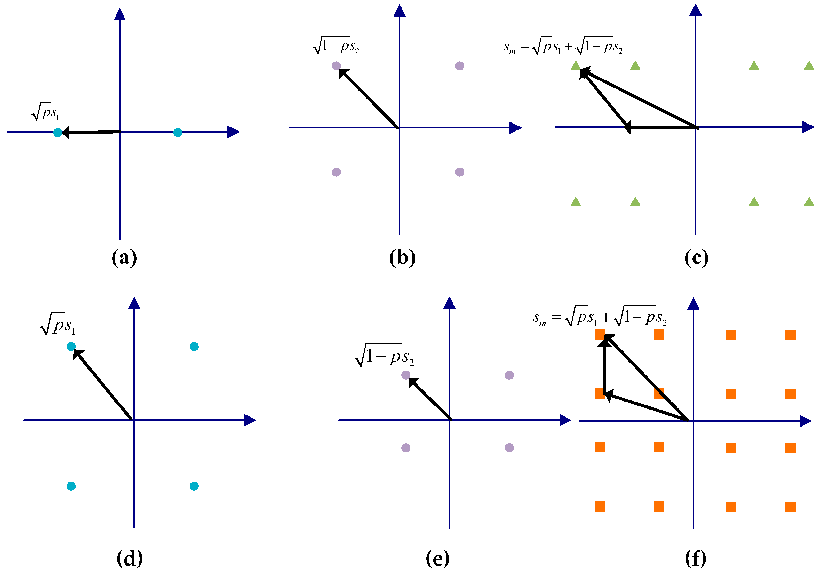
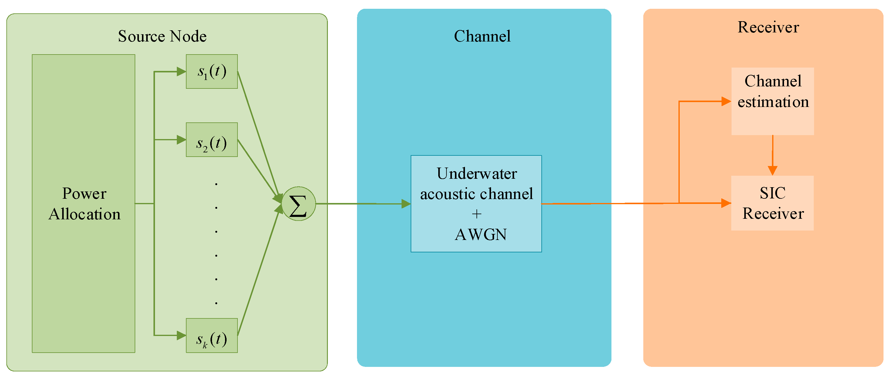
2. Downlink NOMA Underwater Acoustic Communication

The downlink underwater acoustic communication may be achieved by considering a scenario where a single source node is required to broadcast data to many nodes located at varying distances and depths from the source, as illustrated in Figure 1. The use of superimposed coding and power domain NOMA techniques is employed to achieve downlink communication. Figure 2 depicts the superimposed coding vector diagram in scenarios where both users employ BPSK modulation, one user employs BPSK while the other utilizes QPSK modulation, and both users employ QPSK modulation. Initially, the signal is modulated, and, subsequently, the multi-user signal is multiplexed through the use of superposition coding. The allocation of power for each user is influenced by the channel parameter and the receiver’s range or depth. The SIC approach is employed when the receiver encounters channel impairments, such as multipath, delay spread, and multi-user interference. The receiver characterized by a lower channel gain is subjected to decoding, and a significant portion of power is allotted to this receiver. Conversely, the remaining receivers receive a smaller power allocation and are regarded as sources of interference for the primary receiver. Following the correct decoding of the signal with the application of increased power, the signal is subsequently reconstructed. The reconstructed signal is modulated and convolved with the estimated channel to eliminate multipath interference. Subsequently performing the subtraction operation among the reconstructed signal and the received signal, the decoded data after the demodulation of the user with less power are obtained. The aforementioned process is iterated until the recipient is able to decode the intended information. SIC stands out as a very efficient multiple-access technique when considering its impact on uplink and downlink multi-user communication.
Consider a downlink multi-user UWA communication scenario where there is a total M number of users/node and a single source node. The signal of the n t h receiver at the source node is denoted as s n ( t ) , where n = 1 , 2 , 3 M . The user’s allocation power coefficient can be expressed as p n , while the overall transmission power is the summation of all the power allocation coefficients can be represented by P, where  P = p 1 + p 2 + p 3 + + p M . Based on the aforementioned assumption, the composite transmit signal in the presence of AWGN w ( t ) can be equated as:
s M ( t ) = n = 1 M p n s n ( t ) + w ( t )
The composite signal in Equation (1) obtained after a transmission over an underwater acoustic channel is mathematically given as:
y ( t ) = h ( t ) n = 1 M p n s n ( t ) + w ( t )
In the framework of symbol detection employing the SIC algorithm, the primary focus is on detecting the user with the highest power level, while considering all other users as sources of interference. The equations presented herein can be employed for the purpose of determining and decoding the information referring to user 2, while simultaneously mitigating the interference produced by user 1:
s 1 ^ = arg min s 1 q | y p 1 h 1 s 1 |
The variable q represents the constellation point. Ultimately, the detection of the second user’s symbols can be achieved by the use of the maximum likelihood criterion. Equation (4) can be implemented to eliminate the influence of user 2 on the composite signal:
s 2 ^ = arg min s 2 q | ( y k p 1 h k s 1 ^ ) p 1 h k s 2 |
As observed in Figure 3, the SIC method is repeated in an iterative manner until the decoding of the signal associated with the user p is achieved. This objective can be achieved by making a hard decision, that is, by estimating the transmit symbols:
s p ^ = arg min s p q | ( y n = 1 M 1 p 1 h p s n ^ ) p p h p s p |
One of the main limitations associated with the SIC approach is its reliance on having full-knowledge channel state information.

3. Deep Neural Network

Deep learning is a subcategory of machine learning that works on the principle of classical artificial neural networks (ANNs). The ANN faces the problem of a vanishing gradient as the hidden layers are increased [53]. Therefore, to counter this problem, deep neural networks are proposed. The DNN normally consists of a single or multiple input layer and a single/multiple output layer, whereas there are multiple hidden layers. The number of hidden layers in a DNN depends on the complexity of the task it performs. Compared to the ANN, deep neural networks consist of many hidden layers and can classify or predict highly complicated problems requiring very complex mathematical modeling. On the other hand, deep learning requires a large dataset to train a network. The DNN used in this article is a 1D CNN.

1D Convolution Neural Network

The structure of the CNN can be realized by a neural network but has a superior performance compared to the classical ANN. In the past few years, the CNN has dominated various fields, including computer vision, medical image processing, facial recognition, self-driving vehicles, and applications where object recognition is necessary. Since the 1D CNN is inspired by feedforward neural networks, it essentially incorporates a sequence input layer, a 1D convolutional layer, and a 1D max-pooling layer, followed by a global max polling layer, a flatten layer, a fully connected layer, and an output layer. The key goal of convolutional layers is to extract structures from input data. A max-pooling layer is added to minimize the computation by selecting only salient features. Next in the 1D CNN, the architecture is a traditional fully connected layer that consists of several neurons having weights and biases. There can be multiple convolutional and 1D max-pooling layers in a CNN depending upon the complexity of the task it performs. A conventional CNN requires two-dimensional data and it is best suited for images. The alternative for signal processing is the recently proposed 1D CNN [54]. The input to the 1D CNN is a sample of a signal vector. The convolutional filter of the 1D CNN is also of one dimension. The structure of the 1D CNN is presented in Figure 4.

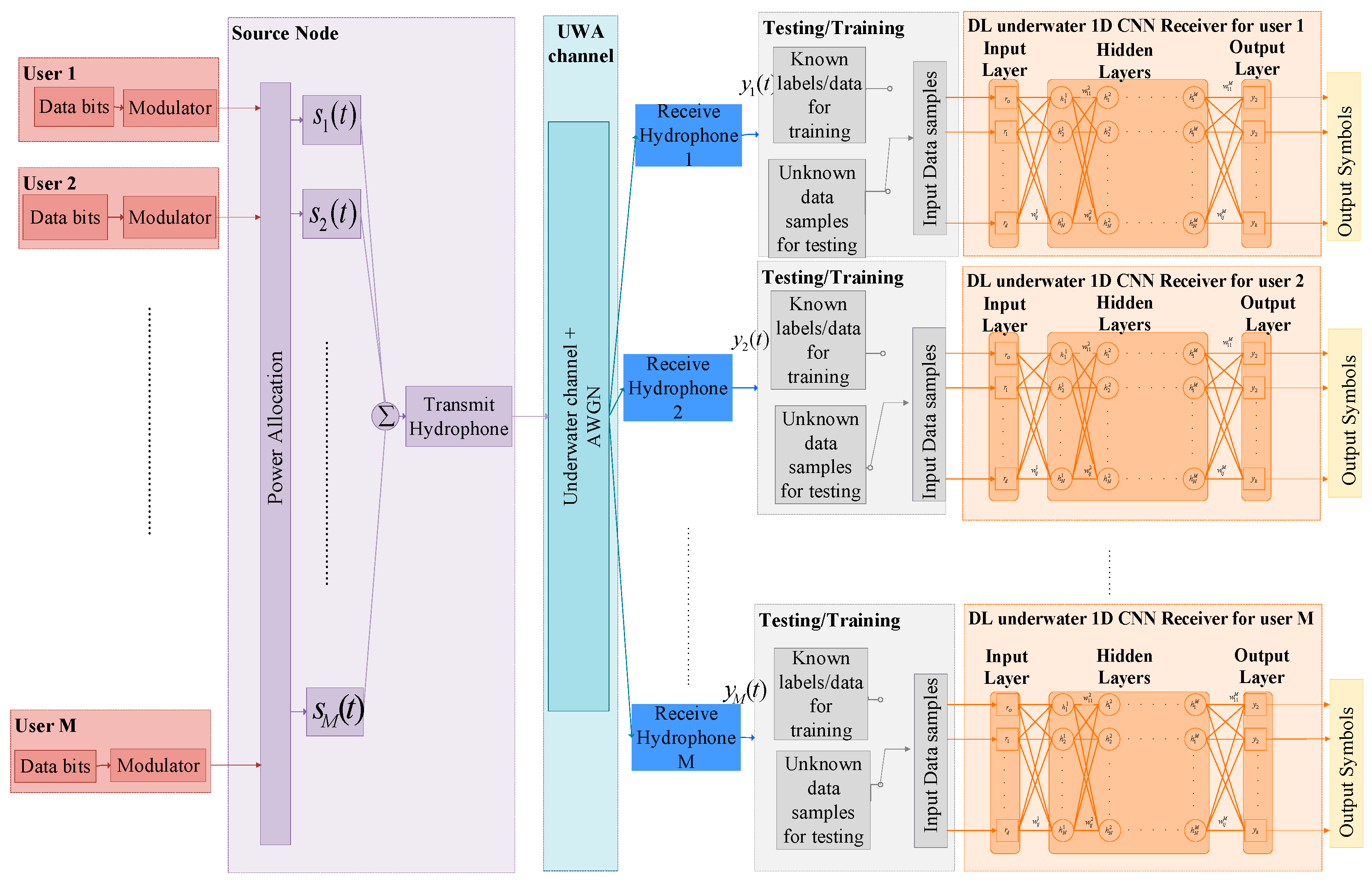
4. Downlink Underwater Acoustic Communication Using a Deep Neural Network Receiver

This section outlines the suggested approach for underwater acoustic communication in the downlink NOMA. The method involves the use of a deep neural network receiver for the purpose of signal detection. First, the input symbols of each user are modulated using QPSK/BPSK modulation techniques. Following modulation, the power coefficient is allocated to individual users by the source station based on variables that include the condition of the receiver’s channel, distance, and location from the source. Furthermore, the technique of superimposed coding is employed to facilitate the transmission of signals from distinct users. The composite signal from all users can be represented by Equation (1). The received signal, after passing through the training UWA channels, is fed into a 1D CNN block at the receiver. The sequence input layer is provided with a set of 1000 samples for each signal, since the sampling rate is 100 K and symbol duration is 10 ms along with their corresponding labels. The diagram in Figure 5 illustrates the suggested concept for downlink NOMA underwater communication. The composite signal samples are fed into the 1D CNN in a sequential manner. After the input layer, the design comprises a sequence of four 1D convolutional layers. The layers possess filter sizes of 250, 120, 60, and 30 in a sequential manner. Furthermore, the number of filters utilized in each layer is 150, 100, 30, and 20, respectively. The convolutional neural network employs the rectified linear unit (ReLU) as its activation function, denoted as g ( x ) = max ( 0 , x ) . The next component in the architectural design is the max-pooling layer, followed by the dropout layer and the flattening layer. Next, we implement a fully connected layer consisting of 120 neurons. The output layer is used to calculate the estimated probability of each symbol. The output layer uses the SoftMax activation function.
The ADAM optimizer is used for weight updates in the 1D CNN model due to its higher efficiency compared to a traditional stochastic gradient descent. The ADAM update rule can be stated in the following manner:
θ r + 1 = θ r ρ u ^ r + ε n ^ r
In the above equation, the estimated first moment is denoted as n r , and the estimated second moment is denoted as u r , which is determined by the decay mean α 1 and decay variance α 2 . Equations (7)–(10) demonstrate the use of past values in the computation of the mean and moment, providing the estimation of the first and second moments.
n r = α 1 n r 1 + ( 1 α 1 ) g r
u r = α 2 v r 1 + ( 1 α 2 ) g r 2
n ^ r = n r 1 α 1 r
u ^ r = u r 1 α 2 r
Once the deep neural network has undergone training to gather knowledge pertaining to the properties of the underwater channel, it can be utilized for detecting transmit symbols, without the need for any reliance on channel state information. For the simulation, two scenarios are being examined: in the first case, only two users are considered, while, in a second case, one more user is added in the system. Two users in the given scenario utilize BPSK and QPSK modulation techniques. These users are situated at distances of 500 m and 1000 m, respectively. The modulated superimposed signal is passed through the underwater test channels and fed to the trained 1D CNN model which is subsequently evaluated. To evaluate the performance of the proposed novel system, the power coefficients assigned to users were modified and, subsequently, the BER of the system was evaluated. In the second scenario, a 1D CNN is trained using BPSK-modulated aggregated signals from three users, and subsequently tested.

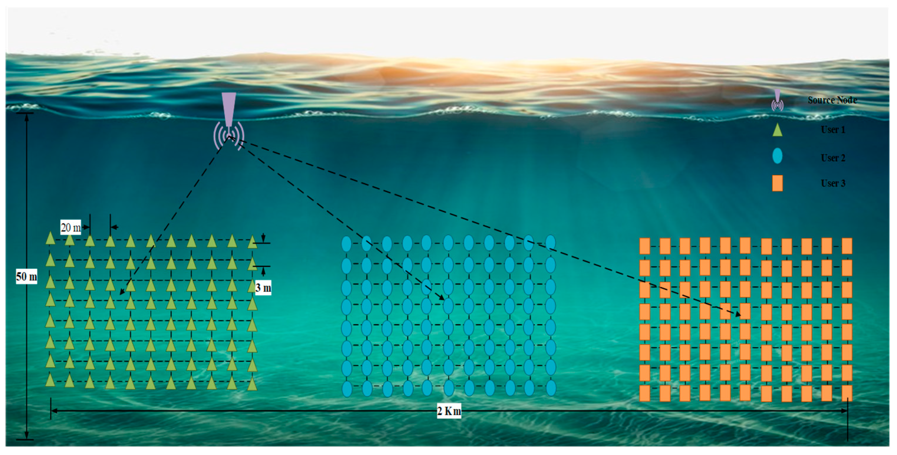
5. Underwater Acoustic Communication Dataset Generation for DL DNN Receiver

This section outlines the methodology employed for generating the dataset utilized in the proposed system. One crucial phase in the process of working with the DNN model is training the DNN model using a diverse dataset before conducting tests with unknown data. It is essential that the DNN model conduct offline training using a specified dataset.
The BELLHOP ray-tracing technique is employed to determine the channel impulse response of the downlink underwater channel. This procedure uses a measured sound speed profile and modifies the range with a step of 20 m and the depth with a step of 2 m of each user from the source node. As a result, 70 channels are obtained, with 20 reserved for real-time testing. The parameters used for generating the channel impulse response are listed in Table 1. Figure 6 illustrates the simulation setup utilized for generating the channel impulse response of an underwater acoustic channel. Figure 7a displays the channel impulse response obtained through the BELLHOP ray-tracing method for training user 1, which is 500 m from the source station. Furthermore, Figure 7b,c illustrates the CIR of user 2, located at a distance of 1 km from the source station, and the CIR of the user 3, located at a distance of 2000 m from the source. In order to obtain a substantial number of datasets initially, a stream of bits is generated for all the users. Furthermore, the bits undergo modulation and the power coefficient is allotted to each user. Subsequently, the modulated signals are superimposed. Two possibilities are under consideration. In the initial instance, two distinct sets of user data were employed for the purpose of training. In the second scenario, the simulation incorporated three users situated at different distances and depths relative to the source.
The superimposed signal is convolved with the CIRs that have been generated for each user, resulting in the final composite signal, which can be expressed as:
y M k ( t ) = s M ( t ) h M k ( t , τ ) + w M k ( t )   k = 1 , 2 , K
The equation above represents the composite signal, denoted as y M k ( t ) , which is formed by convolving it with the k t h CIR of the M t h user, while the term w K n ( t ) represents the AWGN that is present in the received signal. Consequently, a substantial number of datasets is generated for training purposes. The DNN acquires knowledge about the attributes of the UWA channel in the presence of multi-user interference through the diverse dataset.

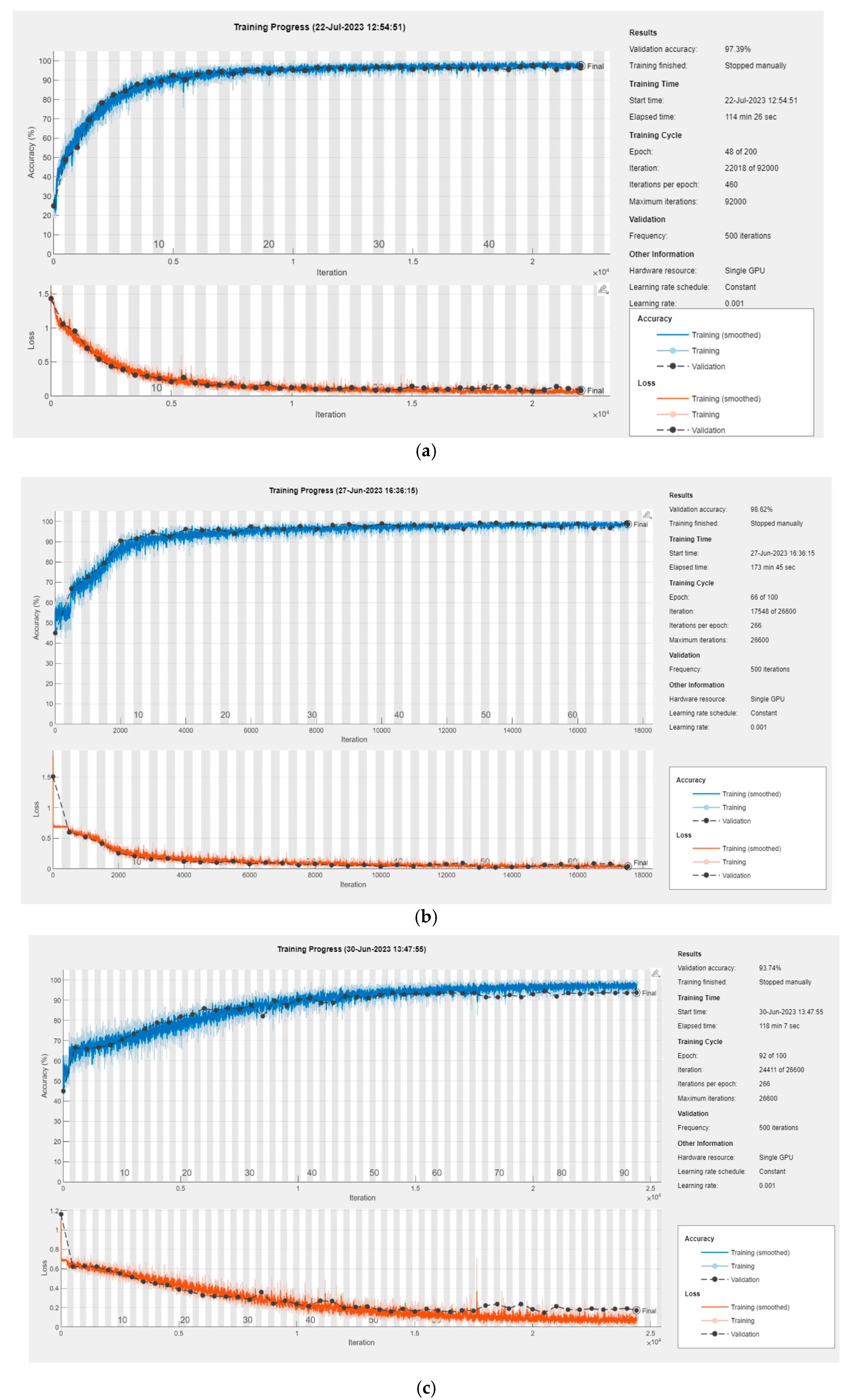
6. Training and Analysis of DNN Receiver

In this subsection, the performance of the training of the proposed novel model is discussed. Figure 8 illustrates the downlink NOMA receiver for training performance, which is based on the 1D CNN. Figure 8a depicts the training process of the receiver associated with user 1, whereby a power allocation of 0.3 is employed while considering two users in the system. The findings indicate that the accuracy of the training progressively improves with an increasing number of epochs, approaching a value close to 99%. On the other hand, a validation accuracy of 97% is attained. The training performance of user 2 at a distance of 1 km is shown in Figure 8b. According to the training performance graph, the accuracy of the training dataset nearly reaches an amount that is greater than 99% as the number of epochs increases. Similarly, the validation performance of nearly 98% is achieve. The DNN training performance with three users included in the training process is shown in Figure 8c. The training results show performance levels exceeding 94% accuracy with a validation accuracy of 93.70%. The training performance of user 3 at a distance of 2 km is shown in Figure 8d. Based on the training performance graph, it can be observed that the accuracy of the training dataset consistently approaches a value exceeding 94% with an increasing number of epochs. Furthermore, a validation performance of approximately 94.40% has been achieved. In order to conduct a more in-depth study, a higher modulation order, namely, QPSK, is employed to train the 1D CNN. The objective is to assess the performance of a DNN-based receiver for higher-order NOMA downlink communication. Two users are taken into account, both of whom have implemented QPSK modulation. Figure 8e illustrates the training performance of the nearby user, located at a distance of 500 m from the source station, with a lower power ratio of 0.3. The validation accuracy of 97.39% is attained by increasing the number of epochs and decreasing the cross-entropy loss. Similarly, the far user, which is at a distance of 1000 m, shows an accuracy of 95.2%, as illustrated in Figure 8f. The trained neural network is tested using test data. The hyper-parameters obtained for the DL multi-user 1D CNN receiver, as determined by the training process, are presented in Table 2 for each user in the system. In the following section, a real-time simulation is used to evaluate the proposed 1D-CNN-based receiver, and the results are examined in relation to those of a conventional SIC receiver.

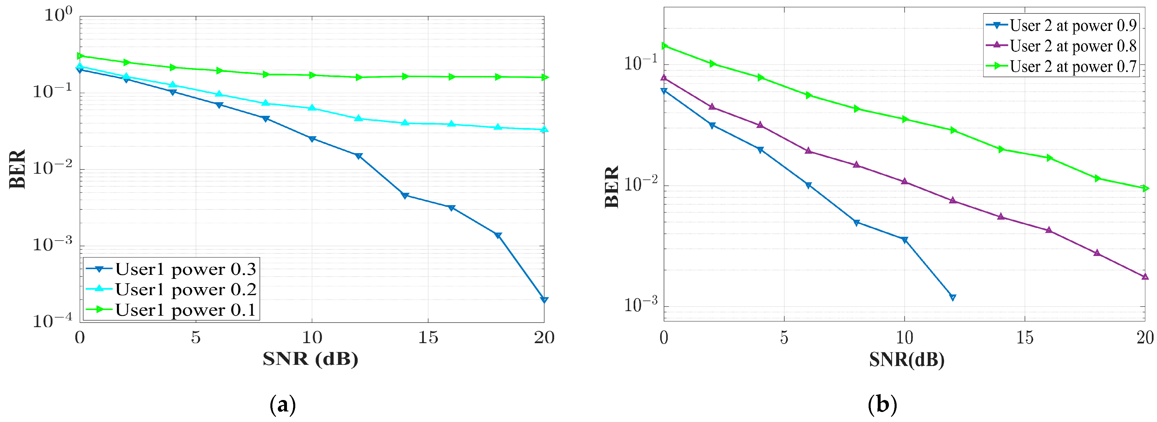
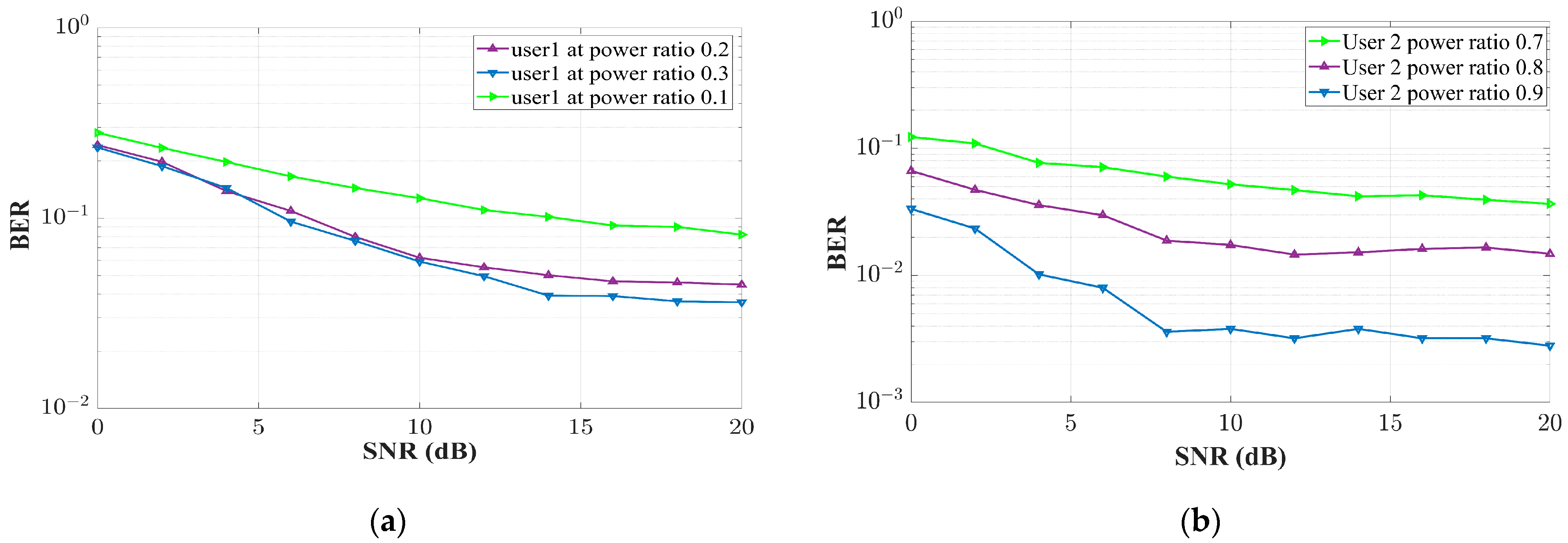
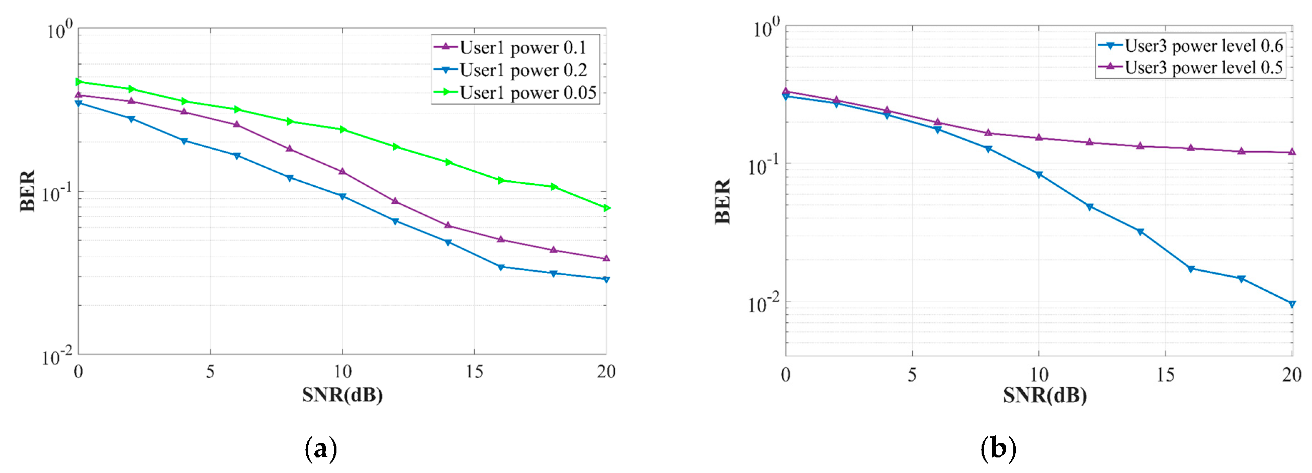
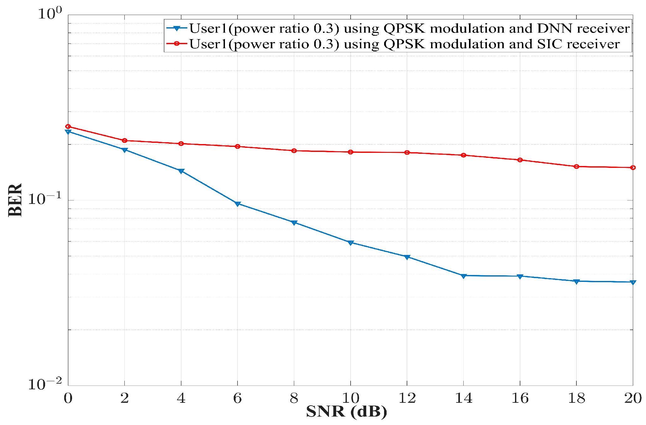
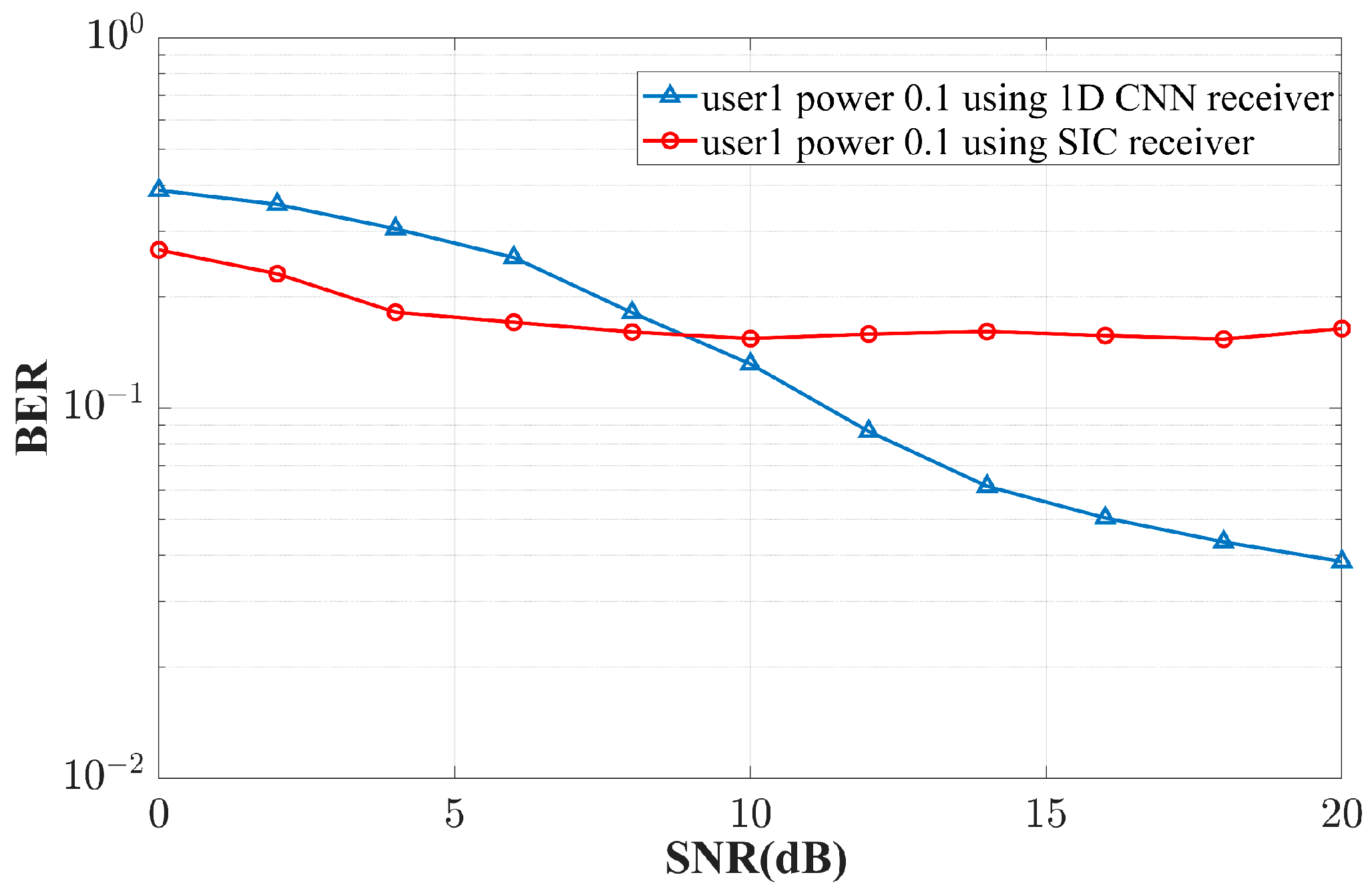
7. Simulation Results and Discussion

The underwater channel parameter settings used in the real-time simulation are the same as listed in Table 1, while the NOMA communication specifications are provided in Table 3. The proposed system was tested using a total of 20 channels. The CIR for test user 1 is shown in Figure 9a. In addition, the test CIRs of user 2 and user 3 are shown in Figure 9b,c, respectively. The source node depth is 5 m. The depth of the users varies from 20 m to 50 m in steps of 2 m, with the first user 500 m away from the source node, while user 2 and user 3 are 1000 m and 2000 m away from the source node. The simulation results were initially evaluated by varying the user’s power level, as shown in Figure 10. The findings indicate that, when two users are present in the system that have undergone initial training, and user 1 is given a power allocation of 0.3, the average BER of all test channels is around 10−4 at 20 dB when there is a total of two users present in the system. Nevertheless, when the power of user 1 is reduced to 0.2 and 0.1, respectively, the BER performance deteriorates. Specifically, at a power level of 0.2, the BER reaches an approximately different power 0.033 at 20 dB, while, at a power level of 0.1, the BER is approximately 0.159. For user 2, the power ratio allocation is set to 0.9, 0.8, and 0.7, respectively. Figure 10b shows the average BER of user 2 at varying power levels. At a power ratio of 0.9, the average BER of the DNN-based receiver for user 2 is around 10−3 at 12 dB and provides error-free transmission after 12 dB. However, as the power ratio of user 2 decreases to 0.8 and 0.7, the performance of the systems degrades and the average BER for 20 test channels is 0.01 and 0.09 at 20 dB for the 0.8 and 0.7 power ratio, respectively.
The performance of the trained deep DNN is also examined when two users in the system employ QPSK modulation. The analysis involves altering the power ratio of user 1 of the system. The BER graph in Figure 11a exemplifies the influence of changing power ratios on the output of the DNN receiver. It is evident that, at a power ratio of 0.3, the DNN receiver achieved an average BER of 0.036. However, as the power ratio decreases, the BER deteriorates. At a power ratio of 0.2, the BER is measured to be 0.044. However, when the power ratio is reduced to 0.1, the BER deteriorates significantly, increasing to 0.08. On the other hand, user 2 showed an average BER of 0.0028 when the power allocation was 0.9, but, as the ratio of power allocation decreases, the BER also increases in Figure 11b.
In the second scenario, three users were initially trained and, subsequently, tested using distinct UWA channel impulse responses. User 1 is 500 m away from the origin station, user 2 is 1 km away from the origin station, and user 3 is 2 km away from the origin station. All three users are utilizing BPSK modulation, and the source station employs superimposed coding to transmit data. The average BER achieved by altering the power level of user 1 is depicted in Figure 12a. The simulation results dictate that, when the power ratio of user 1 is 0.2, the BER at 20 dB is estimated to be 0.029. As the power level decreases, the BER performance becomes worse. For a power level of 0.1, the BER performance is around 0.038, and, for a power ratio of 0.05, the BER of the system decreases to 0.07. For the DNN receiver for user 3, which is at 2000 m from the source node when tested from a 20-test-channel CIR and with a varying power level, the proposed 1D-CNN-based receiver was able to detect data and the average BER of the system at power ratio 0.6 was around 10−2 as shown in Figure 12b. In contrast, at a power ratio 0.5, the average BER decreases to 10−1.
For further investigation, the proposed receiver is compared with a conventional SIC receiver. The simulation results were evaluated using the same parameters described above. User 1 is assigned a power of 0.3, while user 2 is assigned a power of 0.7. When considering two users in the system, the results of the simulation are depicted in Figure 13, showing that the proposed DNN-based receiver outperforms the conventional receiver without a priori channel knowledge. However, it is necessary to estimate the channel of the SIC receiver to successfully perform its operation. Furthermore, SIC receivers also suffer from error propagation, which does not occur in the proposed 1D-CNN-based receiver. Furthermore, a comparison between the proposed DNN receiver and the conventional SIC receiver is also conducted when the modulation order of both users increases from BPSK to QPSK. Figure 14 shows that, when the power ratio of the near user is 0.3 and both users in the system implemented QPSK modulation, the proposed DNN-based receiver completely outperformed the SIC receiver; even at the SNR of 20 dB, the SIC receiver was able to give a BER of 0.176. On the other hand, the DNN was able to reduce the average BER to the value of 0.036. The simulation results of the proposed 1D CNN receiver and conventional SIC receiver when three users are considered is depicted in Figure 15. Real-time simulation results are obtained by assigning a power ratio of 0.1 to user 1 located 500 m away from the source node. Based on the BER results obtained from 20 test channels, it can be seen that the performance of the proposed model initially exhibits inferior performance compared to conventional SIC receivers. Nevertheless, as the SNR of the system increases, the performance of the proposed model demonstrates improvement in comparison to the SIC receiver. Specifically, at an SNR of 20 dB, the SIC receiver exhibits a BER of 0.164, whereas the proposed 1D CNN model achieves a significantly lower BER of 0.0385, indicating its superior ability to accurately decode data.
The analysis further shows that the computing complexity of the conventional SIC is directly proportional to the number of users present inside the system. For instance, if there are M users in a system, the computational complexity of the conventional SIC receiver is denoted as O ( M ) . In the context of a trained 1D CNN model, the task of signal detection refers to the method of forward propagation. The computational complexity associated with this process is denoted as O ( 1 ) . This implies that the 1D CNN model that has undergone training is capable of achieving effective and real-time UWA signal detection. In contrast, it is necessary to have a substantial and varied dataset in order to effectively train a deep neural network using a 1D CNN on a high-performance machine equipped with a graphic processing unit (GPU).

8. Conclusions

The article introduces a receiver design based on a deep neural network for downlink non-orthogonal multiple access for acoustic communication in an underwater channel. The 1D CNN architecture is employed in the development of a receiver for downlink NOMA systems. A synthetic dataset is generated through the utilization of the BELLHOP ray-tracing algorithm to train a DNN. The DNN receivers are trained initially using known bits that are labelled and passed through underwater acoustic channels. Consequently, the receivers acquire knowledge about the features of the underwater acoustic channel and effectively mitigate interference from other users. The proposed receiver, in contrast to the SIC receiver, does not require channel information. In addition, the proposed receiver, according to our investigation, holds the ability to decode the data directly from the low-power signal. This eliminates the need for conventional SIC receivers which need to deal with error propagation challenges. The simulation results indicate that the proposed system is capable of functioning effectively across various power levels. In addition, the performance of the proposed 1D CNN receiver has been demonstrated to be superior to that of the conventional receiver. After a complete analysis, it is possible to conclude that the proposed model exhibits encouraging prospects for downlink NOMA underwater acoustic communication under circumstances where the channel state information is insufficient or absent, and channel conditions are difficult to handle. Moreover, the proposed receiver idea may be extended and utilized for multi-carrier and MIMO downlink underwater acoustic communication.

Author Contributions

Conceptualization, S.L. and H.H.Z.; methodology, H.H.Z. and M.B.; software, H.H.Z.; validation, S.L., M.B. and A.A.; formal analysis, H.H.Z., S.L. and A.J.; investigation, H.H.Z. and S.A.H.M.; resources, S.L., A.A. and A.J.; data curation, M.B. and M.A.K.; Writing—original draft, H.H.Z.; Writing—review and editing, S.L., M.B. and A.M.; visualization, H.H.Z. and S.L.; supervision, S.L.; project administration, A.A., A.J. and S.A.H.M.; funding acquisition, A.A., A.J. and A.M. All authors have read and agreed to the published version of the manuscript.

Funding

This work was funded by the National Natural Science Foundation of China [Grant Nos. 62231011, 11974090, 11774074].

Institutional Review Board Statement

Not applicable.

Informed Consent Statement

Not applicable.

Data Availability Statement

Data are contained within the article.

Acknowledgments

The authors would like to thank Taishan industry leading talent special fund for supporting this research.

Conflicts of Interest

The authors declare no conflict of interest.

References

  1. Campagnaro, F.; Steinmetz, F.; Renner, B.-C. Survey on low-cost underwater sensor networks: From niche applications to everyday use. J. Mar. Sci. Eng. 2023, 11, 125. [Google Scholar] [CrossRef]
  2. Li, S.; Qu, W.; Liu, C.; Qiu, T.; Zhao, Z. Survey on high reliability wireless communication for underwater sensor networks. J. Netw. Comput. Appl. 2019, 148, 102446. [Google Scholar] [CrossRef]
  3. Stojanovic, M.; Preisig, J. Underwater acoustic communication channels: Propagation models and statistical characterization. IEEE Commun. Mag. 2009, 47, 84–89. [Google Scholar] [CrossRef]
  4. Ranjha, A.; Javed, M.A.; Srivastava, G.; Lin, J.C.-W. Intercell Interference Coordination for UAV enabled URLLC with perfect/imperfect CSI using cognitive radio. IEEE Open J. Commun. Soc. 2022, 4, 197–208. [Google Scholar] [CrossRef]
  5. Jiang, Y.; Li, X. Broadband cancellation method in an adaptive co-site interference cancellation system. Int. J. Electron. 2022, 109, 854–874. [Google Scholar] [CrossRef]
  6. Jiang, Y.; Liu, S.; Li, M.; Zhao, N.; Wu, M. A new adaptive co-site broadband interference cancellation method with auxiliary channel. Digit. Commun. Netw. 2022, in press. [Google Scholar] [CrossRef]
  7. Li, A.; Masouros, C.; Swindlehurst, A.L.; Yu, W. 1-bit massive MIMO transmission: Embracing interference with symbol-level precoding. IEEE Commun. Mag. 2021, 59, 121–127. [Google Scholar] [CrossRef]
  8. Li, A.; Masouros, C.; Vucetic, B.; Li, Y.; Swindlehurst, A.L. Interference exploitation precoding for multi-level modulations: Closed-form solutions. IEEE Trans. Commun. 2020, 69, 291–308. [Google Scholar] [CrossRef]
  9. Ranjha, A.; Javed, M.A.; Srivastava, G.; Asif, M. Quasi-Optimization of Resource Allocation and Positioning for Solar-Powered UAVs. IEEE Trans. Netw. Sci. Eng. 2023, 10, 4071–4081. [Google Scholar] [CrossRef]
  10. Asif, M.; Ihsan, A.; Khan, W.U.; Ranjha, A.; Zhang, S.; Wu, S.X. Energy-efficient beamforming and resource optimization for AmBSC-assisted cooperative NOMA IoT networks. IEEE Internet Things J. 2023, 10, 12434–12448. [Google Scholar] [CrossRef]
  11. Morozs, N.; Mitchell, P.; Zakharov, Y.V. TDA-MAC: TDMA without clock synchronization in underwater acoustic networks. IEEE Access 2017, 6, 1091–1108. [Google Scholar] [CrossRef]
  12. Cho, A.-R.; Yun, C.; Lim, Y.-K.; Choi, Y. Asymmetric propagation delay-aware TDMA MAC protocol for mobile underwater acoustic sensor networks. Appl. Sci. 2018, 8, 962. [Google Scholar] [CrossRef]
  13. Yin, J.; Du, P.; Yang, G.; Zhou, H. Space-division multiple access for CDMA multiuser underwater acoustic communications. J. Syst. Eng. Electron. 2015, 26, 1184–1190. [Google Scholar] [CrossRef]
  14. Rahmati, M.; Petroccia, R.; Pompili, D. In-network collaboration for CDMA-based reliable underwater acoustic communications. IEEE J. Ocean. Eng. 2019, 44, 881–894. [Google Scholar] [CrossRef]
  15. Stojanovic, M.; Freitag, L. Multichannel detection for wideband underwater acoustic CDMA communications. IEEE J. Ocean. Eng. 2006, 31, 685–695. [Google Scholar] [CrossRef]
  16. Yang, T. Spatially multiplexed CDMA multiuser underwater acoustic communications. IEEE J. Ocean. Eng. 2015, 41, 217–231. [Google Scholar] [CrossRef]
  17. Wang, Z.; Zhou, S.; Catipovic, J.; Willett, P. Asynchronous multiuser reception for OFDM in underwater acoustic communications. IEEE Trans. Wirel. Commun. 2013, 12, 1050–1061. [Google Scholar] [CrossRef]
  18. Ma, L.; Zhou, S.; Qiao, G.; Liu, S.; Zhou, F. Superposition coding for downlink underwater acoustic OFDM. IEEE J. Ocean. Eng. 2016, 42, 175–187. [Google Scholar] [CrossRef]
  19. Qiao, G.; Xing, S.; Zhou, F. A Multi-User Detection Scheme Based on Polar Code Construction in Downlink Underwater Acoustic OFDM Communication System. IEEE Access 2019, 7, 65973–65981. [Google Scholar] [CrossRef]
  20. Bernard, C.; Bouvet, P.-J.; Pottier, A.; Forjonel, P. Multiuser chirp spread spectrum transmission in an underwater acoustic channel applied to an AUV fleet. Sensors 2020, 20, 1527. [Google Scholar] [CrossRef]
  21. Zuberi, H.H.; Liu, S.; Sohail, M.Z.; Pan, C. Multi-user underwater acoustic communication using binary phase-coded hyperbolic frequency-modulated signals. IET Commun. 2022, 16, 1415–1427. [Google Scholar] [CrossRef]
  22. Yuan, F.; Wei, Q.; Cheng, E. Multiuser chirp modulation for underwater acoustic channel based on VTRM. Int. J. Nav. Archit. Ocean. Eng. 2017, 9, 256–265. [Google Scholar] [CrossRef]
  23. Liu, S.; Zuberi, H.H.; Lou, Y.; Farooq, M.B.; Shaikh, S.; Raza, W. M-ary nonlinear sine chirp spread spectrum for underwater acoustic communication based on virtual time-reversal mirror method. EURASIP J. Wirel. Commun. Netw. 2021, 2021, 112. [Google Scholar] [CrossRef]
  24. Yang, G.; Zhou, F.; Lou, Y.; Qiao, G.; Ahmed, N.; He, Y. Double-differential coded M-ary direct sequence spread spectrum for mobile underwater acoustic communication system. Appl. Acoust. 2021, 183, 108303. [Google Scholar] [CrossRef]
  25. Murad, M.; Tasadduq, I.A.; Otero, P. Coded-GFDM for reliable communication in underwater acoustic channels. Sensors 2022, 22, 2639. [Google Scholar] [CrossRef] [PubMed]
  26. Song, Y. Underwater acoustic sensor networks with cost efficiency for internet of underwater things. IEEE Trans. Ind. Electron. 2020, 68, 1707–1716. [Google Scholar] [CrossRef]
  27. Hussein, H.S.; Alanazi, T.M.; Shamim, M.Z.; Habeeb, M.S.; Usman, M.; Farrag, M. Fully quadrature subcarrier-index shift keying for efficient underwater acoustic communications. IEEE Access 2021, 9, 46975–46984. [Google Scholar] [CrossRef]
  28. Zuberi, H.H.; Liu, S.; Bilal, M.; Khan, R. Quadrature phase shift keying Sine chirp spread Spectrum under-water acoustic communication based on VTRM. In Proceedings of the 2022 19th International Bhurban Conference on Applied Sciences and Technology (IBCAST), Islamabad, Pakistan, 16–20 August 2022; pp. 884–888. [Google Scholar]
  29. Cheon, J.; Cho, H.-S. Power allocation scheme for non-orthogonal multiple access in underwater acoustic communications. Sensors 2017, 17, 2465. [Google Scholar] [CrossRef]
  30. Goutham, V.; Harigovindan, V. NOMA based cooperative relaying strategy for underwater acoustic sensor networks under imperfect SIC and imperfect CSI: A comprehensive analysis. IEEE Access 2021, 9, 32857–32872. [Google Scholar] [CrossRef]
  31. Cho, S.E.; Song, H.C.; Hodgkiss, W.S. Successive interference cancellation for underwater acoustic communications. IEEE J. Ocean. Eng. 2011, 36, 490–501. [Google Scholar] [CrossRef]
  32. Yin, J.-w.; Zhu, G.-j.; Han, X.; Ge, W.; Li, L.; Tian, Y.-n. Iterative channel estimation-based soft successive interference cancellation for multiuser underwater acoustic communications. J. Acoust. Soc. Am. 2021, 150, 133–144. [Google Scholar] [CrossRef] [PubMed]
  33. Lin, C.; Chang, Q.; Li, X. A deep learning approach for MIMO-NOMA downlink signal detection. Sensors 2019, 19, 2526. [Google Scholar] [CrossRef] [PubMed]
  34. Rahman, M.H.; Sejan, M.A.S.; Yoo, S.-G.; Kim, M.-A.; You, Y.-H.; Song, H.-K. Multi-User Joint Detection Using Bi-Directional Deep Neural Network Framework in NOMA-OFDM System. Sensors 2022, 22, 6994. [Google Scholar] [CrossRef] [PubMed]
  35. Shlezinger, N.; Fu, R.; Eldar, Y.C. DeepSIC: Deep soft interference cancellation for multiuser MIMO detection. IEEE Trans. Wirel. Commun. 2020, 20, 1349–1362. [Google Scholar] [CrossRef]
  36. Van Luong, T.; Shlezinger, N.; Xu, C.; Hoang, T.M.; Eldar, Y.C.; Hanzo, L. Deep learning based successive interference cancellation for the non-orthogonal downlink. IEEE Trans. Veh. Technol. 2022, 71, 11876–11888. [Google Scholar] [CrossRef]
  37. Qian, L.; Zheng, Y.; Li, L.; Ma, Y.; Zhou, C.; Zhang, D. A new method of inland water ship trajectory prediction based on long short-term memory network optimized by genetic algorithm. Appl. Sci. 2022, 12, 4073. [Google Scholar] [CrossRef]
  38. Yin, L.; Wang, L.; Li, T.; Lu, S.; Tian, J.; Yin, Z.; Li, X.; Zheng, W. U-Net-LSTM: Time Series-Enhanced Lake Boundary Prediction Model. Land 2023, 12, 1859. [Google Scholar] [CrossRef]
  39. Cao, B.; Zhao, J.; Lv, Z.; Gu, Y.; Yang, P.; Halgamuge, S.K. Multiobjective evolution of fuzzy rough neural network via distributed parallelism for stock prediction. IEEE Trans. Fuzzy Syst. 2020, 28, 939–952. [Google Scholar] [CrossRef]
  40. Shi, J.; Niu, W.; Li, Z.; Shen, C.; Zhang, J.; Yu, S.; Chi, N. Optimal adaptive waveform design utilizing an end-to-end learning-based pre-equalization neural network in an UVLC system. J. Light. Technol. 2022, 41, 1626–1636. [Google Scholar] [CrossRef]
  41. Yao, Y.; Zhao, J.; Li, Z.; Cheng, X.; Wu, L. Jamming and Eavesdropping Defense Scheme Based on Deep Reinforcement Learning in Autonomous Vehicle Networks. IEEE Trans. Inf. Forensics Secur. 2023, 18, 1211–1224. [Google Scholar] [CrossRef]
  42. Zhang, Y.; Zhang, S.; Wang, B.; Liu, Y.; Bai, W.; Shen, X. Deep Learning-Based Signal Detection for Underwater Acoustic OTFS Communication. J. Mar. Sci. Eng. 2022, 10, 1920. [Google Scholar] [CrossRef]
  43. Liu, Y.; Zhao, Y.; Gerstoft, P.; Zhou, F.; Qiao, G.; Yin, J. Deep transfer learning-based variable Doppler underwater acoustic communications. J. Acoust. Soc. Am. 2023, 154, 232–244. [Google Scholar] [CrossRef] [PubMed]
  44. Raza, W.; Ma, X.; Song, H.; Ali, A.; Zubairi, H.; Acharya, K. Long Short-Term Memory Neural Network assisted Peak to Average Power Ratio Reduction for Underwater Acoustic Orthogonal Frequency Division Multiplexing Communication. KSII Trans. Internet Inf. Syst. 2023, 17, 239–260. [Google Scholar] [CrossRef]
  45. Ma, X.; Raza, W.; Wu, Z.; Bilal, M.; Zhou, Z.; Ali, A. A nonlinear distortion removal based on deep neural network for underwater acoustic ofdm communication with the mitigation of peak to average power ratio. Appl. Sci. 2020, 10, 4986. [Google Scholar] [CrossRef]
  46. Zhang, Y.; Li, J.; Zakharov, Y.V.; Li, J.; Li, Y.; Lin, C.; Li, X. Deep learning based single carrier communications over time-varying underwater acoustic channel. IEEE Access 2019, 7, 38420–38430. [Google Scholar] [CrossRef]
  47. Liu, Y.; Zhou, F.; Qiao, G.; Zhao, Y.; Yang, G.; Liu, X.; Lu, Y. Deep Learning-Based Cyclic Shift Keying Spread Spectrum Underwater Acoustic Communication. J. Mar. Sci. Eng. 2021, 9, 1252. [Google Scholar] [CrossRef]
  48. Qiao, G.; Liu, Y.; Zhou, F.; Zhao, Y.; Mazhar, S.; Yang, G. Deep learning-based M-ary spread spectrum communication system in shallow water acoustic channel. Appl. Acoust. 2022, 192, 108742. [Google Scholar] [CrossRef]
  49. Zhang, Y.; Li, C.; Wang, H.; Wang, J.; Yang, F.; Meriaudeau, F. Deep learning aided OFDM receiver for underwater acoustic communications. Appl. Acoust. 2022, 187, 108515. [Google Scholar] [CrossRef]
  50. Zhu, Y.; Wang, B.; Zhang, Y.; Li, J.; Wu, C. Convolutional neural network based filter bank multicarrier system for underwater acoustic communications. Appl. Acoust. 2021, 177, 107920. [Google Scholar] [CrossRef]
  51. Zhang, Y.; Li, J.; Zakharov, Y.; Li, X.; Li, J. Deep learning based underwater acoustic OFDM communications. Appl. Acoust. 2019, 154, 53–58. [Google Scholar] [CrossRef]
  52. Zhang, J.; Cao, Y.; Han, G.; Fu, X. Deep neural network-based underwater OFDM receiver. IET Commun. 2019, 13, 1998–2002. [Google Scholar] [CrossRef]
  53. Roodschild, M.; Gotay Sardiñas, J.; Will, A. A new approach for the vanishing gradient problem on sigmoid activation. Prog. Artif. Intell. 2020, 9, 351–360. [Google Scholar] [CrossRef]
  54. Kiranyaz, S.; Avci, O.; Abdeljaber, O.; Ince, T.; Gabbouj, M.; Inman, D.J. 1D convolutional neural networks and applications: A survey. Mech. Syst. Signal Process. 2021, 151, 107398. [Google Scholar] [CrossRef]
Figure 1. Underwater acoustic downlink communication.
Jmse 11 02184 g001
Figure 2. Constellation diagram of different users when superimposed coding is employed by source station: (a) user 1 BPSK modulation constellation; (b) user 2 QPSK modulation constellation; (c) resultant constellation obtained for two users after superimposed coding of QPSK-BSPK modulation; (d) user 1 QPSK modulation constellation; (e) user 2 QPSK modulation constellation; and (f) resultant constellation obtained for two user after superimposed coding of QPSK-QSPK modulation.
Jmse 11 02184 g002
Figure 3. Downlink-NOMA-SIC-based underwater acoustic communication system.
Jmse 11 02184 g003
Figure 4. 1D CNN architecture.
Jmse 11 02184 g004
Figure 5. Proposed downlink DNN receiver model.
Jmse 11 02184 g005
Figure 6. Simulation setup to generate a dataset for UWA channel impulse responses.
Jmse 11 02184 g006
Figure 7. Training underwater acoustic channel impulse response of various users: (a) user 1 is 500 m away from the source node; (b) user 2 is 1000 m away from the source node; and (c) user 3 is at distance of 2000 m from the source node.
Jmse 11 02184 g007
Figure 8. Training progress of 1D-CNN-based receiver for various users: (a) training progress of user 1 at 500 m from source when two users are considered and using BPSK modulation; (b) training progress of user 2 at 1000 m from source when two users are considered and using BPSK modulation; (c) training progress of user 1 at 500 m from source when three users are considered and using BPSK modulation; (d) training progress of user 2 at 2000 m from source when three users are considered and using BPSK modulation user; (e) training progress of user 1 at 500 m from source when two users are considered and using QPSK modulation user; and (f) training progress of user 2 at 1000 m from source when two users are considered and using QPSK modulation.
Jmse 11 02184 g008aJmse 11 02184 g008b
Figure 9. Testing underwater acoustic channel impulse response of various users: (a) user 1 at a distance of 500 m from the source node; (b) user 2 at a distance of 1000 m from the source node; and (c) user 3 at distance of 2000 from the source node.
Jmse 11 02184 g009
Figure 10. BER vs. SNR graphs of two users having varying power coefficients and using BPSK modulation: (a) BER vs. SNR graph of user 1 at 500 m from the source node when allocated different power coefficient; and (b) BER vs. SNR graph of user 2 at 1000 m from the source node when allocated different power.
Jmse 11 02184 g010
Figure 11. BER vs. SNR graphs of two users having varying power coefficients and using QPSK modulation: (a) BER vs. SNR graph of user 1 at 500 m from the source node when allocated different power coefficient; and (b) BER vs. SNR graph of user 2 at 1000 m from the source node when allocated different power.
Jmse 11 02184 g011
Figure 12. BER vs. SNR graphs of three users having varying power coefficients and using BPSK modulation: (a) BER vs. SNR graph of user 1 at 500 m from the source node when allocated different power coefficient; and (b) BER vs. SNR graph of user 3 at 2000 m from the source node when allocated different power.
Jmse 11 02184 g012
Figure 13. BER vs. SNR comparison graph of proposed receiver and SIC receiver of user 1 in two-user system using BPSK modulation.
Jmse 11 02184 g013
Figure 14. Comparison of BER vs. SNR of proposed receiver and SIC receiver of user 1 in two-user system using QPSK modulation.
Jmse 11 02184 g014
Figure 15. Comparison of BER vs. SNR of proposed receiver and SIC receiver of user 1 in three-user system using BPSK modulation.
Jmse 11 02184 g015
Table 1. Underwater channel parameters.
ParametersValues
Source station depth5 m
No. of users3
Depth of users[20:2:50] m
Distance of user 1[485 m, 515 m]
Distance of user 2[985 m, 1015 m]
Distance of user 3[1985 m, 2015 m]
Transducer beam angle (°)[−20, 20]
Total depth50 m
Table 2. Downlink 1D CNN receiver architecture hyper-parameters.
1D CNN FactorsUser 1User 2User 3
Sequence I/P layer(s)111
Total no. of convolution layer(s)444
Filter size of convolution layer(s)[250, 120, 60, 30][250, 120, 60, 30][250, 120, 60, 30]
Number of filters in convolution layer(s)[150, 100, 30, 20][150, 100, 30, 20][150, 100, 30, 20]
1D max-pooling layer(s)444
Number of flatten layer(s)111
Total number of global max-pooling layer(s)111
Number of neurons in fully connected layer120120120
Total batch size200200200
Hidden layer(s) activation functionReLUReLUReLU
Type of optimizerAdamAdamAdam
Output layer(s) activation functionSoftmaxSoftmaxSoftmax
Learning rate10−310−310−3
Total number of training channels505050
BPSK training dataset (two-user case)50,00050,000NA
BPSK training dataset (three-user case)50,00050,00050,000
QPSK training dataset (two-user case)125,000125,000NA
Table 3. Underwater communication parameters for testing.
Communication ParametersValues
Carrier frequency12 kHz
Sampling frequency100 kHz
Modulation order(s)[QPSK BPSK]
Duration of symbol10 ms
Power allocation coefficient (two-user case)[0.7, 0.3]
Power allocation coefficient (three-user case)[0.6, 0.3, 0.1]
Total number of symbols for testing50,000
Total number of testing channels20
Disclaimer/Publisher’s Note: The statements, opinions and data contained in all publications are solely those of the individual author(s) and contributor(s) and not of MDPI and/or the editor(s). MDPI and/or the editor(s) disclaim responsibility for any injury to people or property resulting from any ideas, methods, instructions or products referred to in the content.

