1. Introduction
Autonomous underwater vehicles (AUVs) include mechanical, electrical, hydraulic, control, communication, and self-guidance systems, as well as other professional and multisystem equipment [
1]. From a technical aspect, the integration level of AUVs is higher, and the influence between different systems and specialties is more comprehensive. Therefore, it is necessary to achieve higher multidisciplinary coupling performance under constraints of small space and weight to meet the requirements of complex and changeable combat tasks and environments, which requires realizing a higher level of integration and interoperability between design tools and multidisciplinary mechanisms. However, at the process level, the development cycle of AUVs is short, and the multidisciplinary collaborative iterating process is fast. Therefore, many system specialties are necessary to realize the design, index evaluation, scheme trade-off, and iterative optimization of the product under a unified R&D system. This requires a higher transmission capacity of technical indicators and extensive design information. However, the existing document-based collaborative development models cannot meet the time and cost requirements of AUVs’ overall integrated design. Therefore, the standardization and modeling of existing design methods and empirical knowledge to achieve the simultaneous and rapid reuse of different development stages are highly desirable and urgently needed.
Model-based system engineering (MBSE) adopts digital models as a general carrier for multidisciplinary information transmission and scheme iteration. MBSE aims to improve the reusability of model knowledge, shorten the iteration cycle, improve the iteration efficiency, and reduce the development cost. Therefore, MBSE has gradually become the main means for the development and design of equipment [
2]. The International Institute of Systems Engineering has emphasized the importance of task analysis in the “
Systems Engineering Manual 4.0” [
3,
4]. General MBSE methods and frameworks (e.g., OOSEM [
5,
6,
7] and HarmonySE [
8,
9]) have been commonly combined to meet the process requirements of specific industries or organizations to obtain domain-based solutions [
10,
11,
12,
13]. NASA’s Jet Propulsion Laboratory established open standards to support MBSE research with multiprofessional positions through the OpenMBEE [
4] project. The European Space Agency constructed a cross-regional virtual integrated environment in a virtual spacecraft project [
5] to promote collaborative modeling and data sharing between multidisciplinary teams. By using the Modelica unified modeling language and FMI interface specification, the entire system model of the aircraft was developed by the DASSAV and LTS to support and conduct the design of an aircraft complex system. Lockheed Martin spent a year converting all the original submarine documents into system models, covering 35 subsystems, 3500 interface requirements, 500 services, 5000 interface solid models, and 15,000 model elements [
14]. The U.S. Department of Defense released the “
Digital Engineering Strategy” in 2018 [
15], which considers MBSE as a core subset of digital engineering. Therefore, it is required to design a digital model that integrates the system model with physical models of various engineering disciplines (e.g., mechanical and electrical engineering) to support the digital demonstration, development, test, operation, and maintenance of equipment systems. The unified architecture framework (UAF) architecture models provide the necessary means to understand complex relationships between organizations, systems, and systems-of-systems and enable the analysis of these systems, ensuring that they meet the expectations of their user communities. The UAF provides a set of rules to enable users to create consistent enterprise architectures (e.g., models) based on generic enterprise and system concepts with rich semantics [
16,
17]. In terms of specific applications, reference [
18,
19,
20] proposed to leverage parallel cosimulation between the plant, model predictive controller, and processor. Gerschütz et al. [
21] discussed the digital engineering methods and developed a hybrid realization model for AUV controllers based on the model-based systems engineering (MBSE) methodology [
22]. Lu, J. et al. [
23] proposed a SPIRIT framework supporting a model-based system engineering (MBSE) tool-chain development method of advanced cyberphysical systems (CPSs) with an emphasis on the tool integration, process management, automated verification, and validation. Reference [
24] has shown how the used models can be abstracted and generalized, enabling an automated consistency check. In general, there have been many studies on how MBSE is defined, what the advantages of using MBSE are, what particular project types and specific life-cycle stages are when MBSE is applied, and what challenges appear in MBSE applications [
25,
26,
27,
28,
29]. MBSE research in China also follows similar technical trends. The Fifth Aerospace Academy performed the design and verification of a spacecraft power supply and distribution system based on domain-specific models [
30] and realized the conversion and integration of the design and simulation models. Based on the SYSML and Modelica models, 11 institutes of the Sixth Aerospace Academy supported the overall design verification of liquid rocket engine models [
31]. In recent years, the MBSE technology has gradually strengthened the analysis and verification of task processes, emphasizing the interoperability between design simulation models, focusing on the construction of the domain model knowledge base, and providing a comprehensive integration ability between the system-level function model and the multidisciplinary performance model, with the objective of improving the overall design verification ability of the system [
32].
Considering specific requirements of design and simulation integration, system and professional integration, and business process integration in the overall design of AUVs, this study develops a model-based overall integrated design method of AUVs. By using a unified architecture, the reconfigurable automatic integration of the system design model, system simulation model, and industry simulation model is realized. The digital model is combined with the system design to realize the rapid design and verification of the system. The overall rapid system design and the multidisciplinary integrated simulation verification are achieved, and the overall integrated design process and specification of AUVs are explored. The consistency of demand index transmission, comprehensiveness of verification and evaluation, clarity of process traceability, and efficiency of iterative optimization are ensured, and the task-oriented comprehensive optimization design of the entire design process of AUVs is effectively supported. Based on a typical AUV formation cooperative combat mission scenario, the requirement model, function model, architecture model, and simulation performance model of a typical AUV are developed, and the requirement, function, and architecture design analyses and simulation verification are completed.
The main contributions of this paper can be summarized as follows:
Based on the technical characteristics of an AUV system, a unified architecture and interface for the system-level design simulation models are defined, solving the interoperability and consistency problems in multiple tools and models;
A model-based AUV system integration design verification method that combines different processes, specifications, models, and tools is developed, providing technical means for the system-level integrated design;
Taking a specific AUV equipment as a research object, a practical system design is conducted, and the proposed methods are compared with traditional methods to prove the improvement effect of the technical route on the equipment and development efficiency.
The remaining sections of the paper are as follows:
Section 2 presents the overall integrated design method of AUVs.
Section 3 describes the design and simulation integration technology. The multidisciplinary collaborative specification is established in
Section 4.
Section 5 provides a detailed description of the model-based overall integration design method for AUVs.
Section 6 describes the validation process of the method proposed in this paper.
Section 7 concludes the paper.
2. Overall Integrated Design Method of AUVs
During the overall design process of AUVs, multiple models, including task scenarios, functional logic, architecture design, system simulation, and detailed simulations, are required. These models typically contain various model elements, such as tasks and environments, as well as multiple interface forms, such as communication, control, and electromechanics. In addition, different modeling methods, such as black- and white-box modeling, should be supported at different levels of granularity. As a result, a large number of various models with different structures, levels, granularities, and modeling forms are generated during the system design process, resulting in the need for technical solutions for maintaining consistency between these models and ensuring that all closed-loop processes in the overall design process have a unified model data source. This paper addresses these challenges and presents solutions for achieving consistency in the overall AUV design.
This paper presents a research framework for design and simulation integration based on the unified architecture framework (UAF) [
16,
17], as shown in
Figure 1. The proposed framework follows the traditional MBSE process and employs a continuous closed-loop flow of mission task analysis, system architecture design, performance simulation modeling, and simulation-based trade-off verification as the main axis for validating different stages of the AUV system design process. In addition, the proposed framework explicitly defines the sequence and specific requirements of the top-down design decomposition and bottom-up integration verification activities.
To facilitate information exchange between different models and tools in various development stages, the proposed framework adopts the XML Metadata Interchange (XMI) standard file format, enabling interface mapping and parameter passing. It establishes a unified data structure that integrates the overall architecture of an AUV system and its subsystems, components, and elements, as well as data models, data types, and data attributes. Multiple mission task indicators are used as unified parameters to drive the AUV system, thus ensuring the multidisciplinary integration of mechanical, electrical, control, power, guidance, and self-navigation systems. The proposed framework provides a knowledge base for rapid integration.
Further, by using the proposed design and simulation integration framework, design teams working on AUV systems could effectively manage and maintain consistency between diverse models encountered during the design process, which could differ in structure, level, granularity, and modeling forms. The proposed framework facilitates a seamless information exchange, which enables an efficient integration and verification of different subsystems and components. This research contributes to the field of AUV system design by providing a powerful and unified approach for AUV model-based design and simulation.
As shown in
Figure 1, in the mission analysis and system architecture design phase of AUV systems, a unified framework, a data structure, and a parameter-driving approach are used. In addition, based on the SysML language, system concept models, requirement models, functional models, architecture models, and interface parameters are constructed. Further, by using XMI as a foundation, the models, architectures, interfaces, and parameters used in the mission analysis and architecture design phase are converted into executable Modelica system performance simulation models. The joint simulation between the Modelica models and the SysML language is performed using the Jython language, when conducting the system simulation verification.
Based on a unified architecture, a modular approach is implemented to achieve the mission analysis, architecture design, simulation model development, and verification in the context of AUV systems, as shown in
Table 1. This modular approach enables the independent design, development, and expansion of individual components of an AUV. Adopting the unified architecture allows for adding, replacing, or upgrading various parts of an AUV, which can enhance system flexibility and scalability.
By adopting the unified data structure, the consistency of underlying data in various model types is achieved, enabling the construction of a concept master model that can be shared across multiple stages, such as design and simulation, as shown in
Table 2. In the AUV mission design phase, the concept and architecture models are defined. By using the unified data structure at the core level, the extension of the architecture design model to the simulation model is supported, which simplifies the process of simulation modeling while ensuring the consistency of design and simulation model data. Further, by combining the hierarchical interface relationships, the model framework can be continuously expanded, thus allowing for a fast integration and invocation of existing model libraries, thereby facilitating the multistage design verification.
Furthermore, by describing the requirements, functions, architecture, and interfaces of the AUV mission using the unified data structure, they can be edited into structured parameter files. These structured parameter files can then be interpreted as AUV mission requirements, concepts, architectures, and simulation models, achieving an integrated approach for the design and simulation model parameters.
Moreover, by using a unified parameter-driven design and simulation modeling approach, a linkage mechanism between the design and simulation functionalities is established, as shown in
Table 3. Similar to the model consistency checking method [
33], this paper checks the data type, interface relationship, and other parameters based on the unified relationship and parameters to achieve a parameter association mapping and consistency checking between the visual design model and the simulation model. In addition, a bidirectional operation mechanism between the design and simulation models is established. Namely, through the designed functional module of AUV tasks, the simulation model can be called, modified, and run to perform design and simulation calculations rapidly and optimize solutions obtained based on the simulation results.
3. Design and Simulation Integration Technology
Design and simulation integration technology aims to integrate design and simulation functionalities to enable a synchronous simulation and analysis during the design process, thus improving design efficiency, reducing errors, and accelerating product development. The unified architecture provides a comprehensive framework and an organizational structure, integrating the design and simulation tools while facilitating data sharing and collaboration. The standardized interface defines the communication and data exchange methods between the design and simulation tools. In addition, the unified model describes design and simulation-related information, ensuring consistency and accuracy. Finally, by applying the unified architecture, interface, and model, a seamless connection is achieved, which enhances the product design efficiency and quality.
3.1. Unified Architecture
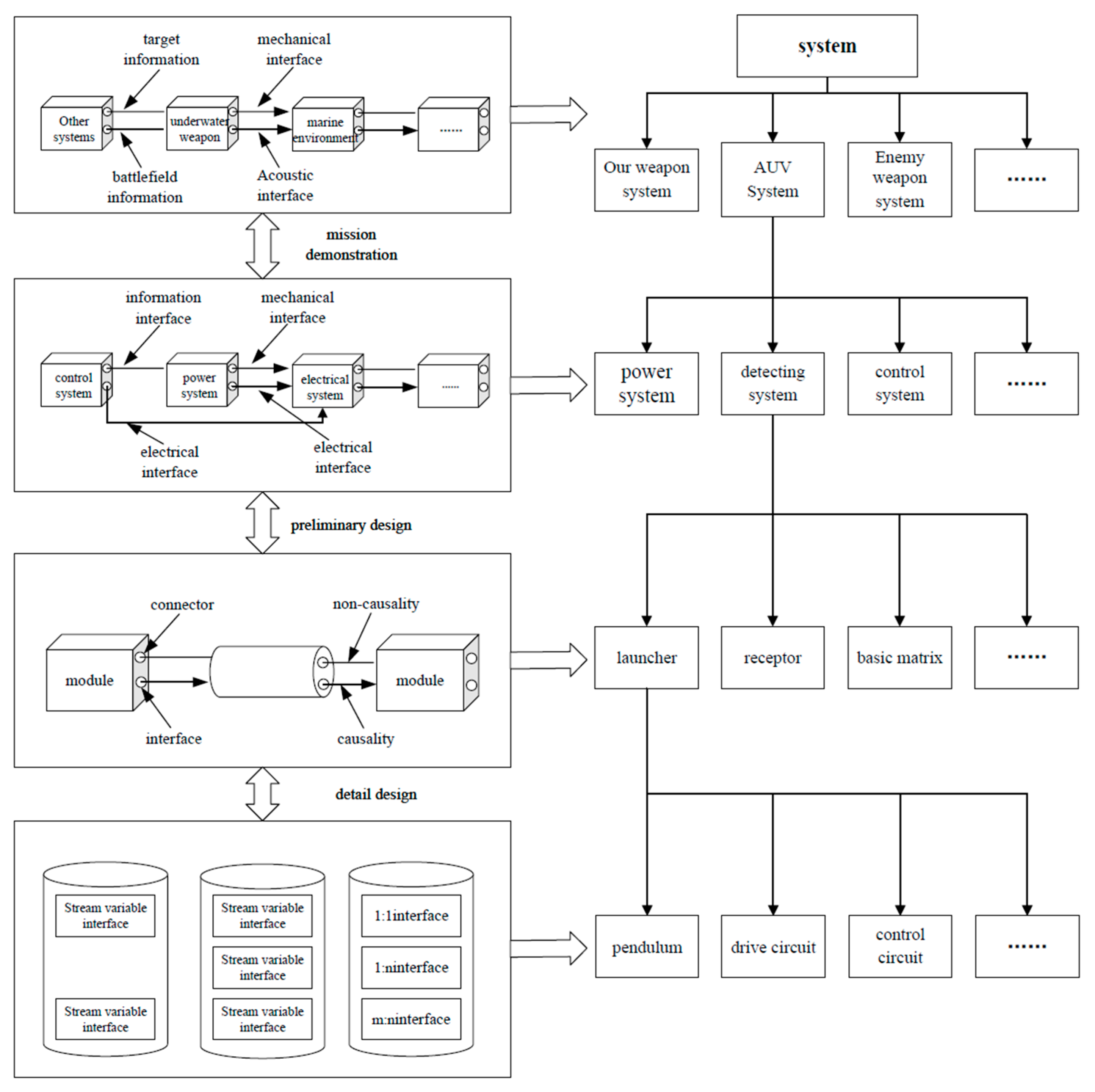
In the AUV development process, the unified architecture refers to the use of the overall and unified model to describe the structure and behavior of an AUV. By being inspired by the UAF approach and considering the system architecture, task scenario, common components, and development stage, this study divides the overall and unified model into several business components that can be executed independently, as shown in
Figure 2 [
16,
17]. Moreover, the model is established according to the life cycle and version revision process. In this study, system configuration and component models of different granularity are investigated. By constructing the mapping relationship between the architecture of an AUV and the interface of modeling and simulation framework, an adaptive reconstruction of a multilevel, multigranularity, and multiversion model driven by the architecture is realized. Next, the assembly customization and expansion of the AUV system model are supported by an extensible plug-in.
In the unified architecture, the unified modeling language is used to represent the composition form of the model. Next, the hierarchical structure–component relationships of an AUV are described. This article refers to the concept and framework definition of controllers of an AUV given in [
22] and combines the composition relationships of other typical subsystems, such as the AUV power, detection, and communication, to clarify the hierarchical structure, interface specifications, and interaction methods of various professional systems, including power, detection, control, and communication systems, thus ensuring both coordination and consistency between various subsystems and components.
The hierarchical structure, interface specification, and interaction mode of each professional system, such as the power, detection, control, or communication system, are defined to ensure the coordination and consistency between each subsystem and component. Furthermore, the unified architecture also includes the task processing and functional logic of the AUV, such as the overall processing of the strike chain, including the launch, detection, tracking, and damage stages. Simultaneously, it can also be used to clarify the optional schemes in different self-guided forms, as well as various ballistic schemes to realize the overall abstraction of the system’s functions and logical architecture.
The construction process of a unified architecture in an object-oriented manner can meet the requirements of both simulation and theoretical models. In the application process, a model can be flexibly configured according to a particular technical scheme, and the model instantiation can be completed in the form of parameterization. Based on the index information on the model library, the design metamodel library and the simulation model library can be integrated and invoked. The iterative procedure of the design process of AUVs allows a dynamic adjustment and interface configuration modification during system development to meet different design and integration requirements.
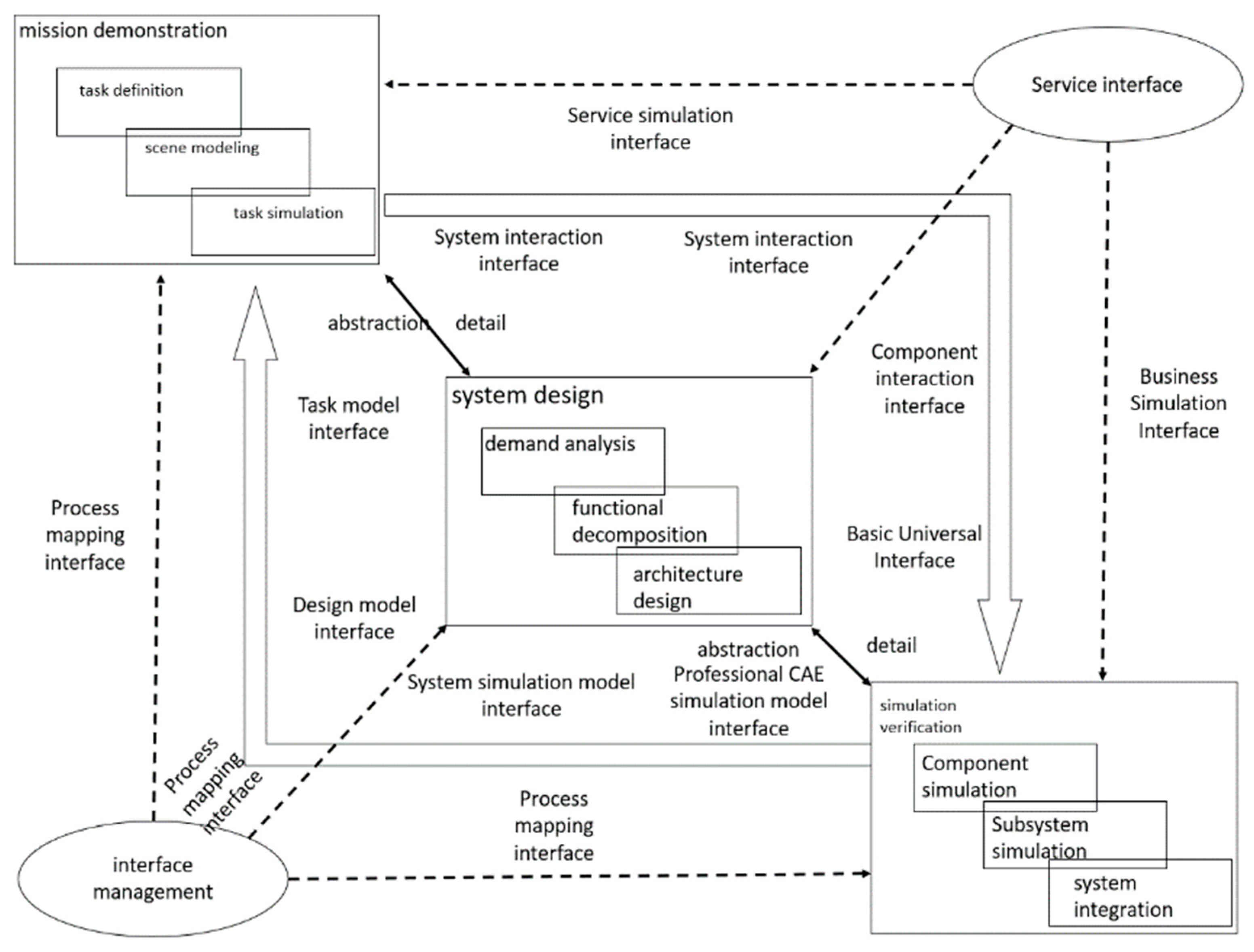
3.2. Unified Interface
The AUV model has hierarchical characteristics. For different development stages of AUVs, different particle-size models are generated, and their interfaces are defined, as shown in
Figure 3. In the early demonstration stage, the information and interactive interfaces between the AUV and external systems are defined, but only the basic task logic, the professional interface, and the top-level message event interface model are described. In contrast, in the system-architecture design stage, the clarification of the mechanical, electrical, and information interface relationships between the AUV and the launch platform, target, and marine environment is necessary to form an interface relationship index table. In the detailed design stage of the overall system and its subsystems, it is necessary to define fully the detailed interface types and interface parameters to determine the interface protocols that each professional interface needs to follow; moreover, various design and simulation model interfaces that are consistent with it are defined.
Based on the operational characteristics of an AUV, three types of interfaces, namely information, control, and energy interfaces, are constructed, as shown in
Table 4. By combining the internal and external interface relationships of an AUV, such as detection, self-guidance, control, and power performance values, the range of interface types is defined.
According to the continuous expansion mode of the technical schemes in each stage, a multilevel, multiprofessional, and multitype interface object model of the system is designed, and its generalization, implementation, dependence, association, aggregation, and combination relationships are analyzed. Based on the object-oriented polymorphic characteristics, a configurable AUV task interface model system is constructed to support the call of different view models, as shown in
Table 5. Further, based on the object-oriented abstract inheritance characteristics, the definition of different granularity interface models is achieved, and the continuous refinement path of the multistage interfaces is defined to support the progressive evolution of the models in different stages, including the stages of mission performing, task realization, requirement definition, concept design, and architecture construction.
Aiming at specific design requirements of the simulation model, the general design interface requirements are transformed into a special interface model for design simulation, which provides parametric calls to the outside, as shown in
Table 6. Further, it supports the parameter-driven interface type, granularity, and professional automatic instantiation generation, such as the interface mapping and transformation relationship between the designed model and the simulation model and the interface mapping and transformation between the system simulation model and the subsystem CAE detailed simulation model.
3.3. Unified Model
Aiming at the entire procedure of the AUV task design and verification process, the corresponding model system framework is studied based on the modeling and simulation requirements of each link, as shown in
Figure 4. In addition, related software research and development work is conducted in different development stages, while simultaneously integrating the AUV system design and simulation through a unified framework. Related software is shown in
Table 7.
According to the 3D structure of the Hall system engineering, this study proposes a 3D system model framework consisting of the system level, process activity, and knowledge logic. In the system-level dimension, which includes the overall system, subsystem, product, and other levels of the project, the digital logic relationship and model requirements are organized, and the granularity and interface relationship of the model are defined. In the process-activity dimension, considering the needs of the model at different stages of the demand analysis, functional decomposition, architectural design, and system verification, the model design and the layout corresponding to the activity are studied. In the dimension of professional knowledge, a domain model library supporting the modeling requirements, such as requirements, functions, logic, and physics, is constructed to improve modeling efficiency and quality. The three dimensions can be extended to support more development stages, product levels, and specialties and to form more complex digital cubes.
According to the above-mentioned design and verification process of AUV tasks, the system modeling process includes four parts: demand analysis, functional analysis, architecture design, and simulation verification. Each part is divided into different model levels, such as the overall system, a subsystem, and a component of an AUV according to the system’s hierarchical structure. In addition, each type of model is divided into different subsystems, including the power, detection, control, and communication subsystems, according to professional knowledge. The requirement model is constructed and managed in an itemized form for requirement management and traceability verification, and this model includes requirements for AUV development, operational index system effectiveness, launch platform interface, confrontation capability, verification index, and experimental test. The design model is developed using the SysML language, which has been used for AUV task definition, requirement analysis, AUV function decomposition, architecture design, and functional design, including structure, behavior, and parameters. The overall simulation model of an AUV is constructed using the Modelica language. Based on the generalized Kirchhoff’s law and declarative modeling, the unified modeling of the heat flow, electricity, detection, communication, control, and other domains is realized. Further, the unified modeling supports the joint simulation with the detailed professional simulation tool of electromechanical measurement and control and the unified model verification requirement index.
4. Multidisciplinary Collaborative Specification
An AUV system represents a complex integration system consisting of multiple disciplines, such as mechanical, electrical, and control technologies, and requiring the collaborative involvement of professionals from different fields. Due to the diversity of expertise and personnel, there can be certain variations in the understanding of the same problem. Therefore, it is necessary to establish a multidisciplinary collaboration standard. By establishing such a standard, a set of common standards and methods to be followed in the design and verification process is defined. Namely, by using standardized procedures and guidelines, misunderstandings and errors can be significantly reduced, and collaboration effectiveness can be improved. The multidisciplinary system specification ensures a unity of understanding among different team members by clearly defining the terminology, symbols, and agreements used in the design and modeling process. This can also help to avoid communication barriers and misunderstandings, improve the accuracy and efficiency of information transmission, enhance the quality of design and modeling, reduce errors and defects, and increase the consistency of modeling results, avoiding discrepancies between team members. Furthermore, this specification provides a scalable and maintainable framework for design and modeling. The application of standardized methods and metrics helps to reduce system complexity and facilitates the continuous evolution and maintenance of design and modeling.
By referring to previous research [
34,
35] on the multidisciplinary collaborative design framework for AUVs and based on relevant work [
36,
37] and literature materials [
38], this paper defines a multidisciplinary collaboration standard, as shown in
Table 8. This standard summarizes different standards and specifications applied to the AUV design process’s phases. Moreover, this standard provides support for a better implementation of the proposed design–simulation integrated framework.
The data obtained in this study are presented in
Table 8, where the formulation of the MBSE standard specification system suitable for AUV missions based on the specific characteristics of AUV missions, considering the two levels (i.e., the general standard layer and the application standard layer), is provided. The objective is to support the development activities in different stages, such as requirement demonstration, conceptual design, and design verification. The MBSE universal basic standard represents the basis of the other standards in the standard system, having broad guiding significance. The application standard mainly defines the guidance specification for a specific development process of AUV tasks, including the process specification, design and simulation verification technical specification, technical management specification, and other types of specifications.
Based on the framework of the standard specification system, this study focuses on the professional application of AUVs and considers specific application standards from the following two aspects: (1) model-based design and technical specifications verification and (2) model-based AUV task design and technical management specifications verification.
According to the specific methodology of the model-driven AUV task design and verification and the characteristics of the AUV task development, the activities of design, analysis, and verification in the process of collaborative design modeling are analyzed and standardized. Moreover, the operational process specification of the model-based AUV task collaborative development is defined, which includes the model-based requirement collaborative demonstration process, model-based AUV task collaborative design process, model-based AUV task collaborative verification process, and other processes. The key tasks of the model-based AUV task design generation process, such as demand analysis, function decomposition, and architecture design, are analyzed using the key structured information such as input, output, and process. Next, the design generation process is unified with the interpretation granularity of the overall design elements. According to the structural information matching between the key tasks of the design generation process and the overall design elements, the mapping framework between the generation nodes of the AUV design process and the overall design elements is constructed. The standardized definition of the output of various common design elements and design process nodes summarized by using the model is provided. Further, the input and output models and delivery specifications of each process node and design stages of the AUV are established.
According to the characteristics of the model category, metadata, and symbol code of specific outputs, such as the designed model and simulation model, of the model-based AUV task design and verification technology, the corresponding management specification is defined. Based on the relationship between the requirements of all levels of the development process of AUV tasks to identify the mutual coupling and influence relationship between these requirements and realize the dynamic analysis of the influence domain of demand change, the requirement management specification of AUV tasks is defined. Aiming at the task reuse of AUVs, the version management mechanism and model label customization of the model library are studied, and the management specifications of the standard and general model library are defined.
5. Model-Based Overall Integrated Design Method
As mentioned above, the model-based overall integrated design method of AUVs uses different granularity models to perform system design verification in different stages of AUV development by using the unified architecture. This method can be divided into several parts: task analysis of AUVs based on the scene model, system design of an AUV oriented to the functional logic, and overall verification based on the detailed professional model integration.
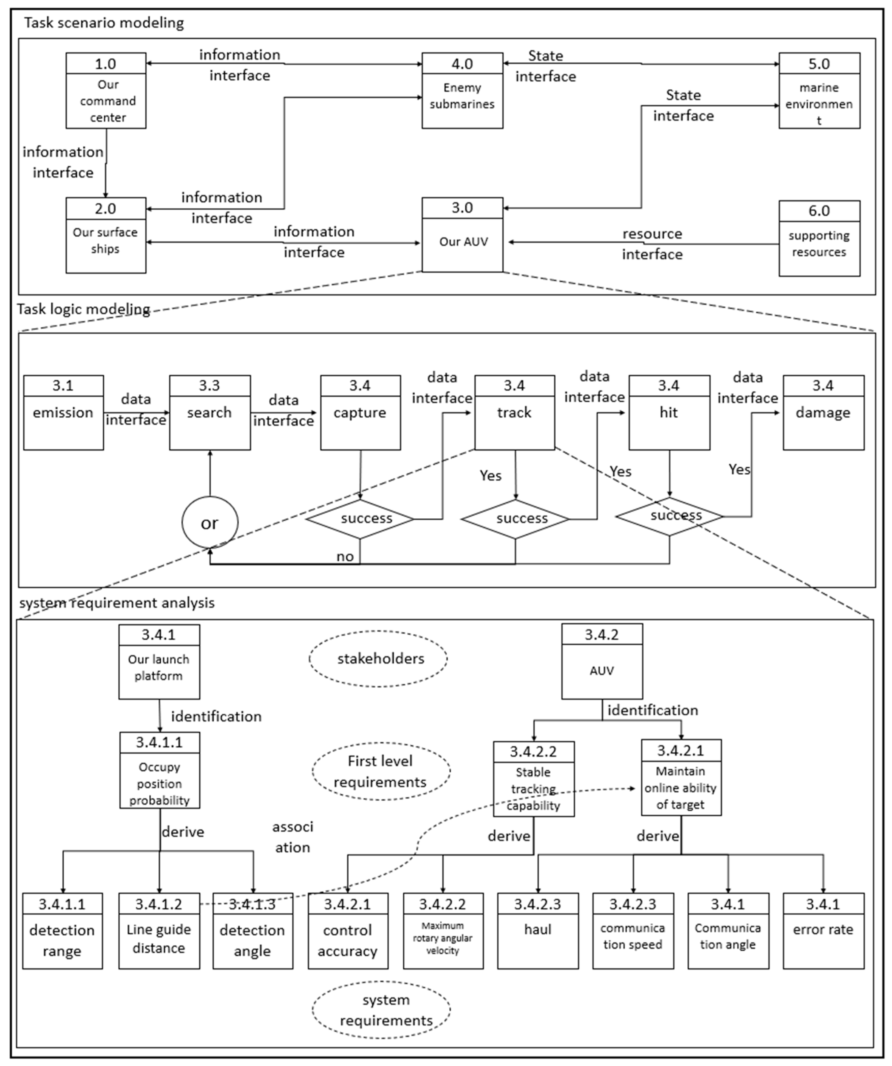
5.1. Task Analysis Based on Scene Model
The task scenario model is developed to describe the requirements and functions of AUVs in different task scenarios, and the system concept definition and index design are performed. The task scenario modeling process can be decomposed into three main parts: task scenario modeling, task logic modeling, and system requirement analysis, involving four specific models of system resources, mission tasks, system task logic, and system requirements. The system resource model represents the general basic model for task analysis and verification. The mission task model indicates the initial work of AUV MBSE. The system task scenario is identified and further refined into the system task logic model to achieve the overall description of the task process, define the system functional requirements, and form a demand model.
The relationships between different models in the task analysis process are shown in
Figure 5.
- (1)
Task scenario definition
According to the combat mission mode of AUVs, typical mission scenarios are identified, and the use-case diagram model of each scenario is established. For typical combat mission tasks and scenarios, system context data, such as task curves, environmental factors, and various stakeholders, are identified; a use-case model of task scenarios is constructed; the task use cases are decomposed and allocated, and a digital task model and structured and quantifiable task requirements are defined. In each scenario, it is necessary to consider the characteristics of the marine environment, including the ocean depth, water velocity, and salinity, and to identify the main participants in the relevant mission scenarios, including enemy targets and launch platforms;
- (2)
Task logic analysis
According to the system task requirements, the system task model is constructed, and the behavior logic of the task process is described by the activity diagram, sequence diagram, state diagram, and other behavior diagrams. The model description and refinement of different granularity, such as black and white boxes, are performed to complete the definition and analysis of the system function logic. For each scenario, a formal and emulatable behavior model or a logic model is constructed, which includes a behavior model (or a logic model) described by the state machine, activity, and sequence diagrams, and a constraint expression related to the parameters is derived.
- (3)
System requirements analysis
Following the task requirements and indicators and considering typical task scenarios, this study defines the main functions and capabilities required for the task. By using the design knowledge of each major function, the calculation relationship between the indicators and the parameters is determined, and the boundary conditions of each technical indicator and design parameter are defined by the constraint model. Through the top-down decomposition and distribution of demand indicators layer by layer, the requirements are decomposed from the system, subsystem, and subsystem-to-component levels in a level-by-level manner to realize the functions covering the particular requirements. The task, system, and subsystem requirements are described as constraint models to realize the quantitative description of itemized demand indicators and support the rapid satisfaction of the requirements.
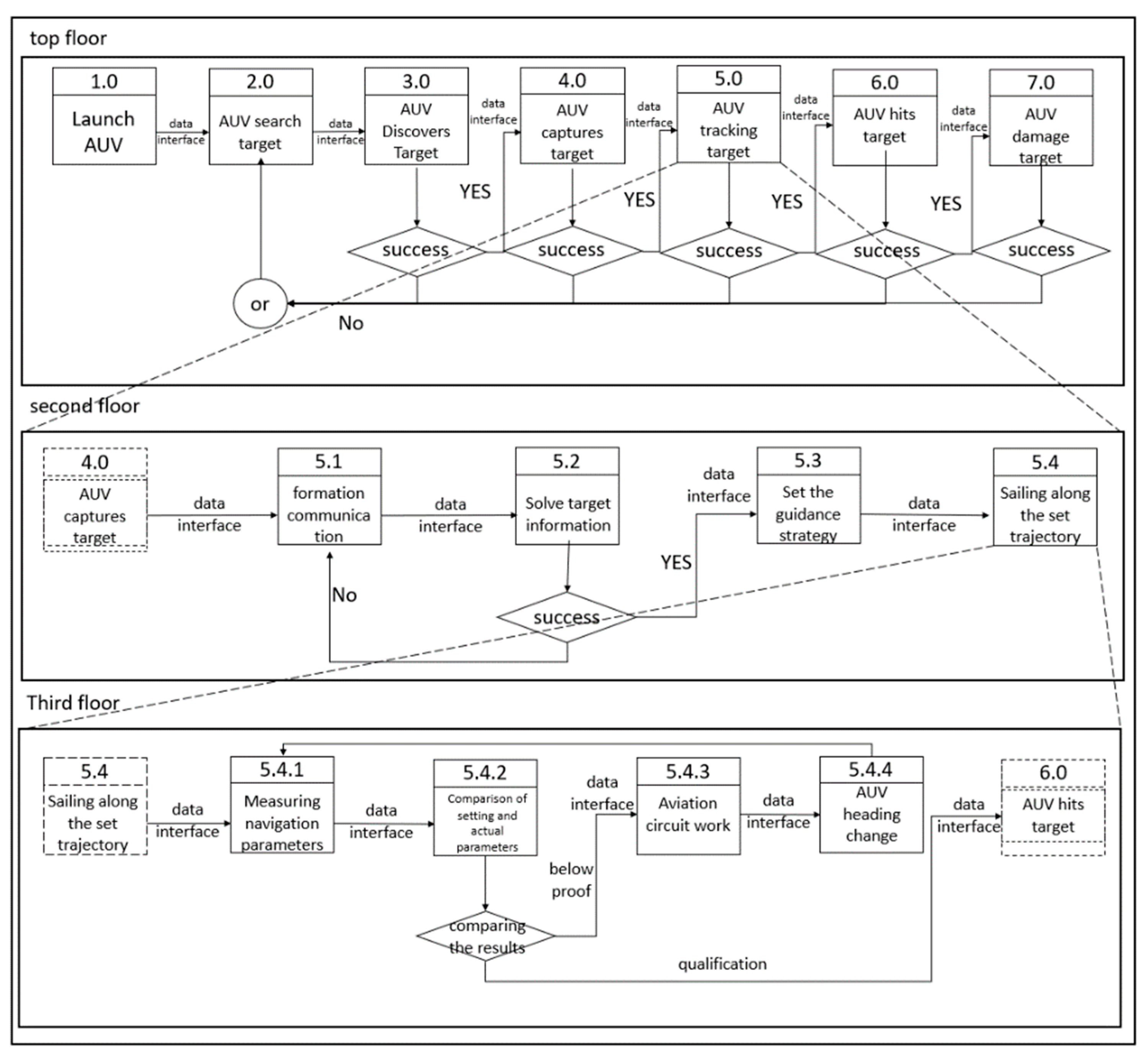
5.2. System Functional Logic Design
The AUV is divided into different functional system modules, each of which realizes particular functions of AUVs in specific combat mission scenarios, such as detection, navigation, tracking, and hitting. In the system design stage, the unified framework of the system model is used as a template, the reusable part is inherited, the personality part of the specific technical scheme is redefined, different functional and system modules of the AUV are developed, the physical interface and data exchange mode between the functional modules are explained, and the specific architecture model is constructed to meet the context requirements of the AUV in a combat mission scenario, as shown in
Figure 6.
- (1)
System architecture design
Based on the division of functional modules of AUVs and considering the actual physical structure topology of AUVs, the functional design of AUVs is performed based on the function–architecture mapping relationship of the model. The functional modules of AUVs are refined and split by using the example, activity, state, and sequence diagrams. Moreover, the behavior index parameters and input and output parameters of each functional module are determined. For instance, an AUV needs to have the function of target tracking. Based on the black-box use case diagram, the activity, sequence, and state diagrams of an AUV’s target tracking process are refined, and an AUV is required to have the functions of group communication, target data collection, guidance strategy provision, sailing along the trajectory, and automatic navigation changing. Based on the above-mentioned functional modules and considering the actual physical structure topology of an AUV, the navigation and control system carrying the tracking target function module is designed, and it includes the communication, navigation, and control systems. The navigation system can be further divided into a gyroscope, an accelerometer, a depth gauge, and other structural parts according to their functions. The control system includes the controller, steering gear, rudder angle, central processor, and other components necessary to achieve its function of course changing. Based on the functional logic process, the design process of an AUV from the black-box task concept to the white-box system is finally realized. Through the analysis of relevant attribute parameters of different groups of components, such as measurement and control errors, combined with the constraint inspection, the system design is verified to meet the functional requirements.
- (2)
Functional module design evaluation
The system concept architecture, function white-box requirements, and system module refinement definition are inherited, and the interface between each module is refined, as shown in
Figure 7; the block diagram and internal block diagram are used to design the system, subsystem, and group component attribute parameters of each functional module of an AUV. Then, the function of each module generated in the function design process is described as a module function or an activity definition, and the constraint relationship is used to check whether the design index meets the function index.
In the module design process, considering the interoperability of the design simulation model and common object-oriented characteristics and using the conversion mapping technology of the design modeling language and simulation modeling language, the simulation model, including the system composition architecture and logical relationship, is developed to generate simultaneously all types of behavior diagrams in the design model, which are then used to drive the simulation model to run; finally, the complete system function simulation verification is realized. The existing similar simulation models can reversely convert the system design model framework, including technical indicators, design parameters, and input and output interfaces. Moreover, it can solidify it into a selection design module for each system and component, which can support the rapid definition and verification of each component module.
- (3)
Interface design
The system design based on the functional logic requires the definition of interfaces and data transmission methods between different modules of AUVs and those between internal components of the same functional module. Furthermore, it is necessary to determine the input and output parameters, data formats, and data transmission methods between different functional modules and components.
5.3. Overall Verification Based on Detailed Model Integration
Referring to the general MBSE process method, this study uses the SysML language for the design of AUVs’ architecture and the Modelica language for the system simulation verification. Both languages are object-oriented system modeling languages, so they are interlinked at the architecture level and can realize mutual conversion and integration. The system architecture model designed by the above-mentioned construction process is converted into the Modelica simulation model framework at the overall system level, including the structural relationship, interface relationship, and parameter composition. At the subsystem level, the multidomain simulation model of each specialty is associated with the subsystem or group component design model, as shown in
Figure 8. It supports the simulation verification of the subsystems and group components and can enhance the system simulation model framework into a complete simulation model, realizing the comprehensive integration and evaluation optimization of the simulation model of the entire system.
- (1)
Simulation model integration
The existing systems’ subsystem design models are based on the simulation verification model consisting of the design and simulation conversion modules, whose parameters are strongly correlated. However, in the design stage, the system behavior model and the architecture model are used to achieve the rapid compilation and solution of the simulation verification model. The solution results verify the system requirements and index parameters for realizing the dynamic calculation and evaluation of the overall integrated design of the system.
Based on the proposed unified architecture of the system design and simulation, the interface description relationship is investigated, and the simulation model is explored in detail in combination with the declaration relationship of the interface of various professional, detailed simulation models. The main objective is to form the joint simulation model of the entire system to achieve a more refined simulation of system performance.
- (2)
System requirements and performance evaluation
The system function verification includes the demand coverage analysis and demand tracking analysis. Within the input analysis of the overall system scheme, different subsystem schemes are compared and analyzed, and the demand coverage matrix and demand tracking tree diagram are constructed and examined. By comparing the reliability, cost-effectiveness, ease of use, inherent characteristics, and other relevant aspects, the weights of different demand indicators are assigned. Finally, different schemes are comprehensively evaluated, and the best design scheme is obtained by performing a manual evaluation.
- (3)
Overall-system trade-off optimization
The overall system has different requirements for each subsystem in different task scenarios. For the same task scenario, some indicators are coupled and deviate from each other. However, in the overall integration design, it is necessary to achieve a comprehensive balance and optimization of different task scenarios and the overall requirements to realize the overall iterative optimization of AUVs.
6. Proposed Method Verification
In this study, the AUV formation cooperative attack on an underwater target was used as a mission background, and the maximum hit probability of the AUV formation attack target was selected as an optimization target. The design and verification of the typical performance and functions of the overall AUV formation and its power, detection, and control subsystems were completed, covering key links, such as demand acquisition, demand and function analyses, architecture design, and simulation verification.
The overall integrated design flowchart of the AUVs is presented in
Figure 9. The overall integrated design process of the AUVs was divided into three parts: the AUVs’ mission demonstration stage, the AUVs’ overall forward design stage, and the AUVs’ overall simulation verification stage.
In the mission task stage, the mission task was completed based on the unified architecture. The AUV mission system included the target ship, marine environment, launch platform, and AUV formation. Based on the unified interface, the mechanical, acoustic, signal, and information interfaces in the mission task demonstration stage were defined. By analyzing the stakeholders, the core demand indicators of different stakeholders in the mission task stage were extracted, which mainly included the maximum combat effectiveness, the launch platform’s shooting position probability, hit probability, damage probability, and AUV’s adaptability.
In the overall forward design stage of the AUV, the overall demand index of the AUV was calculated based on the mission task demand index, which mainly included the speed, range, self-guided action distance and sector angle, control accuracy, fuse action distance, and charge quantity. Based on the unified architecture, the AUV was divided into different subsystems, including the structural, power, detection, navigation control, circuit information, and communication systems and the warhead. Based on the unified interface, the system interface was refined to form mechanical interfaces, such as translation and rotation, acoustic interfaces, such as sound source and noise, and electrical interfaces, such as strong electricity and weak electricity. Based on the above-mentioned interface and requirement–function–architecture decomposition analysis, the overall design model of the AUVs was constructed, which included the attribute index, interface composition, and subsystem composition attributes. Based on the SysML–Modelica transformation mapping relationship and XML file, the unified architecture and interface data conversion were conducted to obtain the architecture definition, interface definition, and index allocation of the simulation model.
In the AUV simulation verification process, based on the converted architecture and interface, the construction of the overall AUV’s simulation model was completed by following the corresponding physical principle. Based on the joint simulation, the interface and index of some subsystems that required a fine simulation were associated with their corresponding CAE simulation models to complete the transmission of simulation results. According to the Modelica language, the overall index of the AUVs was calculated. Combined with the modular and serialized index and mechanism model, different calculation results and subsystem components were embedded in architecture design software to achieve an automatic optimization of different schemes and obtain a trade-off design of different indexes.
6.1. Unified Definition of Architecture and Interface
In the process of overall integrated design, based on the principles of standardization and consistency and according to the system function and structural composition of typical AUVs, the abstract composition relationship of the basic model and data was described. According to different task requirements, such as those of the task analysis, system design, and simulation verification, the composition relationship and interface forms of the system were identified, as shown in
Figure 10. According to the internal system parameters, model parameters, structural parameters, and other dictionary content, the basic model architecture was instantiated. Thus, combined with the basic model libraries, such as those of the system design, system simulation, and professional simulation, it was possible to rapidly generate specific model examples, such as tasks, requirements, architectures, and simulations.
In the process of overall integrated AUV design, the unified interface system was further defined to ensure the consistency and integration of the system model, support the interoperability of the design simulation models, and data exchange and sharing between different systems, components, and elements and promote the synergy of design work. As shown in
Figure 11, at the model granularity level, the interface relationships of different abstraction levels were defined, which included abstract interfaces, such as thermal, fluid, mechanical, and electrical interfaces, to meet the simulation requirements of different scenarios. At the application evolution level of the interface model, for the integration relationship between different simulation software tools, as well as for the integration relationship between the simulation model and the test data, the mapping relationship between the abstract interface type and the model interface parameters and the design of the simulation tool API were obtained. According to the modeling work required for different business scenarios and using the abstraction and instantiation relationship of the interface model, the models at all levels were automatically invoked. Further, combining the model syntax, semantics, and model invocation relationship, the bottom interface type was identified to detect the correlation mapping relationship between different models and realize the rapid conversion and invocation between heterogeneous simulation models of different specialties.
6.2. Mission Demonstration
As shown in
Figure 12, taking the AUV attacking an underwater target as an example, based on the aforementioned design–simulation integrated framework, AUVSysbuilder software was used in the mission analysis and system architecture design phase to analyze the AUV mission process based on the case diagrams. By conducting a profile analysis of the AUV system’s combat missions, relevant operational requirements were identified. After issuing the requirements and refining the use cases, the functional analysis and architecture design of the AUV were conducted. Once the AUV architecture was obtained, the SysML-Modelica plugin was used to convert the AUV design model into a simulation-validating model directly by populating the corresponding Modelica principal models, achieving a unified architecture, interface, and model for the AUV design simulation. As depicted in
Figure 12, typical combat scene setups for the Modelica validation models were constructed using Sysplorer software. The Jyphon plugin allowed for the cosimulation of activity diagrams from AUVSysbuilder with the Modelica models, and the simulation results were fed back into AUVSysbuilder software, thus ensuring a comprehensive validation of the requirements. Thus, the entire AUV design and validation processes were performed in a closed-loop manner based on a unified architecture, interface, and model.
First, the use case analysis of AUVs attacking underwater targets was conducted. The participants included the launch platform and the target, and the attack process mainly consisted of three parts: the platform launching AUVs, the AUVs attacking the target, and the AUVs damaging the target. The part of AUVs attacking the target included searching for the target, capturing the target, tracking the target, and hitting the target. After hitting the target, the AUV’s detonator would trigger the explosives to damage the target. The detonator could be of two types: contact detonator and noncontact detonator. Through the aforementioned profile analysis of the AUVs’ mission process, this study identified the stakeholders and relevant system requirements of the AUV system. By refining different use cases, the white-box functions of the AUV system at different task stages were obtained. Further, by associating the AUV system composition with its system functions, a specific architecture design model for the AUV was constructed. Due to the space limitation, this study does not describe the process of refining functions and associating them with the architecture.
Furthermore, in
Figure 12, the primary-level requirements of the system are presented. The ultimate requirement for the AUV was the operational effectiveness requirement, which could be further refined into five categories of operational requirements: target-detection probability requirement, target-capture probability requirement, target-tracking stability probability requirement, target-hit probability requirement in the final trajectory, and target-damage probability requirement. Each requirement had a unique identifier and the corresponding text description for additional clarification of the requirements.
Upon obtaining the architectural design of the model, the SysML-Modelica plugin was used to associate the Modelica mechanism models with different subsystems and components of the AUV system, creating a simulation verification model that corresponded to the unified architecture, interfaces, and metrics parameters of the design model. By adding the corresponding three-dimensional body models, visualization was achieved, and the AUV’s different subsystems and components were used to construct mission task simulation verification models. Further, by using the design verification model in conjunction with simulation plugins and linking the activity diagrams and simulation verification models in the design model through Jython scripts and UDP communication protocol, interoperability and data transmission between the design and verification models were achieved. At each activity node, the activity diagram waited for the simulation model to obtain the results before proceeding to the next activity. This completed the full validation loop of the AUVs, and through multiple virtual target-shooting exercises, the verification of the probability-based requirements of the AUV system could be realized.
6.3. Overall AUV Forward Design
Based on the demonstrated mission task indicators, different use cases and requirements were refined and allocated, and the system and subsystem functions required by the AUV were analyzed. The function decomposition and analysis were performed using the state-machine diagrams, activity diagrams, and sequence diagrams. Further, based on the actual physical product analysis results, the AUV architecture consisting of the above-mentioned system and subsystem functions was constructed; the AUV white-box architecture is shown in
Figure 13. Based on the unified interface and architecture, the interface definition and architecture definition of the AUV system, subsystem, and group components were obtained. The system exchanged data with the external acoustic interface and mechanical interface, and the data transmission and sharing within the system were performed through the mechanical, information, and signal interfaces.
In terms of data indicators, the architecture covered the functions through the function and architecture relationship, and the functional behavior indicators were assigned to the architecture attribute parameters to generate the architecture–function parameter association relationship. Based on the correlation between the architecture attribute parameters and the functional behavior index parameters, the full coverage of the architecture of the function was realized.
Table 9 presents the architecture types and attribute parameters of the navigation control system in the overall AUV forward design.
Based on the unified architecture and interface relationship, the AUV design architecture and interface were transformed into the AUV simulation model architecture definition and interface definition. Further, according to the unified data structure, the AUV architecture attribute index was passed to the AUV simulation verification model, and the design–simulation integration of the AUV based on the unified architecture, interface, and data structure was realized.
6.4. Simulation Verification of Overall Performance of AUV Formation
The AUV simulation model is shown in
Figure 14. By constructing the corresponding simulation model of the theoretical model designed on the structural sketch, the input and output interface types were modified accordingly, and the simulation model architecture was generated based on the design architecture. Further, based on the analysis of the actual physical principles in the simulation architecture, the corresponding simulation principal design and filling of the simulation framework were performed, and the simulation models of subsystems, systems, and systems were constructed. The study case used in this work included the marine environment, the target system, and the AUV. The target system and the AUV were connected through an abstract interface. The AUV was refined and included four typical subsystems: power, navigation control, communication, and detection subsystems. The dynamics and kinematics simulations with high requirements for the propeller and rudder were conducted based on the unified interface call relationship, and the cosimulation was performed using the propeller CFD simulation results. In the noise analysis, noise analysis software was used for the joint simulation to achieve the simulation verification of the entire structure and different types of models of group components, subsystem, and system.
Based on the integrated simulation model of the entire system, various functional performance simulations, such as hit probability analysis, were performed. The hit probability is the most important index to reflect the combat capability of an AUV, and it is closely related to the main performance indexes of the AUV. Currently, the trajectory hit probability is mainly simulated using the analytical method or simulation method. The model involved the performance model of each system, and the coupling between the models was complex. Further, based on the unified architecture, interface, and data structure, this study completed the forward trajectory design process of the AUV mission task stage, the overall design stage, and the overall verification stage. Based on the SysML–Modelica and cosimulation method, the transmission of the design architecture, interface, and parameters from the bottom to the simulation model and the integration of simulation model results from the top to the design architecture attribute parameters were realized. The verification process of the hit probability index of the AUV attack trajectory was performed using the parameter diagram.
The hit probability was calculated by:
where
P is the hit probability;
K denotes the empirical constant coefficient;
Pa is the capture probability;
Pt is the tracking probability;
Pas denotes the probability of capture in the horizontal plane;
Pah represents the vertical in-plane acquisition probability;
S1 and
S2 denote the relative search widths of the self-guided sector;
= 0.47694;
K1 and
K2 denote the upper- and lower-half search widths of the self-guided sector on the vertical plane;
Eh is the comprehensive probability error of the AUV and target walking in depth;
Pat represents the probability of maintaining a reliable acoustic contact between the homing device and the target during the AUV tracking process;
Pp is the pursuit probability of the AUV catching up with the target during the powered voyage; and lastly,
Pr is the probability of the AUV re-searching and reattacking to recapture the target and maintain a reliable acoustic contact during the powered voyage until it catches up with and hits the target.
6.5. Application Effect Analysis
Next, the traditional MBSE method (TMBSE) [
9] and the traditional document-based development method (TDBD) [
39] were used for a comparative analysis to verify the specific application effect of the proposed model-based overall integrated design (MBOID) method. The above-mentioned three development methods were compared from three aspects: the overall performance index parameters, trajectory hit probability, and efficiency. Through the above three methods, the overall performance design of a typical AUV was carried out under multiple constraints such as the same length (≤7 m), weight (≤1500 kg), diameter (≤535 mm), and rotational body. The comparison of the design results is shown in
Table 10.
As shown in
Table 10, when the development and price adjustment based on the document transfer were performed, the iterative cycle and integrated optimization ability were limited. The hit probability of the final design scheme based on the file transfer reached 88%. The traditional MBSE design method could effectively improve the hit probability, reaching a value of 93%. The proposed method was used to construct a unified model framework and realize the unified integration of various design and analysis models. Therefore, in terms of the integrated design verification effect, it could integrate various professional decentralized analysis algorithms with the physical system models based on the overall design definition of the architecture scheme. The integrity, coverage, and performance parameters of the traceability requirement analysis and scheme parameter optimization were significantly improved. The results indicated that the proposed method could better reflect the mechanism coupling characteristics of different levels and specialties and achieve a better iterative optimization effect than the conventional method. The proposed method could obtain a better overall matching combination of the performance parameters than the other methods. The hit probability could reach about 96%.
In terms of efficiency, due to the improvement achieved by combining the time input of statistical requirements, functional, architecture design, and simulation verification analyses, as well as of the other stages compared to the document-based development method, the proposed method and the traditional MBSE method could significantly improve the development efficiency. Furthermore, compared to the traditional MBSE methods, the proposed method could increase the development efficiency and reduce the development time by approximately 20%. In particular, in the system architecture design stage, due to the fact that the method proposed in this paper can solve the problems of design and simulation model interoperability and interface mapping, while ensuring the consistency of design and simulation model data and achieving an integrated design and simulation, the simulation’s model-driven fast iterative verification could be achieved. By performing sufficient simulation verification in advance, the number of iteration cycles was decreased, and the time reduction in this stage reached 50%. Moreover, the research results obtained by the proposed method could support the subsequent experimental verification study. Finally, the multidomain simulation model could support the subsequent digital experimental verification, which could be helpful for performing the experimental verification of the combination of the digital model and physical system.
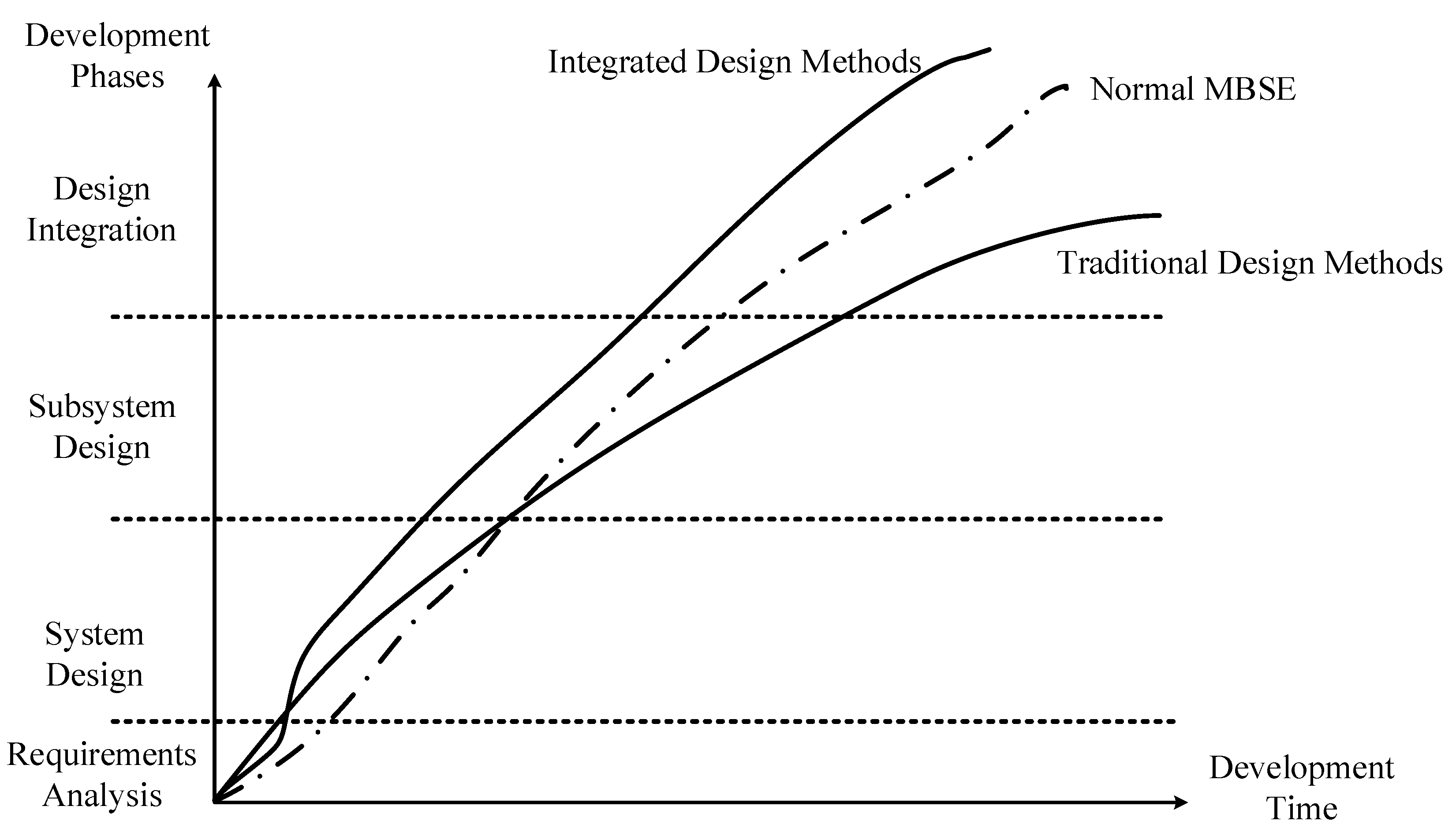
Based on the aforementioned case verification, a more detailed technical analysis of the complete development process of AUVs and other complex equipment was conducted using three methods, as shown in
Figure 15. As presented in
Figure 15, the MBSE approach allowed for the concurrent simulation and validation during the requirement verification phase of the AUV overall design. This ensured that the requirements, functionalities, architecture, and detailed designs of each development stage met the desired objectives. Compared to the traditional document-based design methods, where the concept design was validated after the initial design phase, the MBSE approach had shorter iteration cycles and lower costs for error correction.
However, in typical MBSE approaches, there is a disconnection between the design model and the simulation model. Therefore, during the transition from the system design architecture to the simulation validation, problems of inconsistent architecture, incongruent models, and uncorrelated parameters can arise. These problems can further result in a poor consistency of the system architecture, interfaces, and parameters, a low conversion efficiency, and long cycle times. In the simulation validation process, there has rarely been a joint simulation of the simulation validation model and the system design model, requiring a manual correlation for each validation and causing longer iteration cycles, fewer iterations, and lower efficiency. To address these limitations of the traditional MBSE methods, this paper proposed a method and a toolchain that combined design and simulation. After defining the design architecture, the proposed method used plugins based on the architecture, interface, and parameter correlations to convert the corresponding components and subsystem principles into simulation validation models automatically via a single click. Further, by constructing the task validation system and performing the joint simulation between the simulation validation model and the design model, which included the transfer of computational results, a truly unified architecture, a unified interface, unified parameter end-to-end driving, and full model integration were achieved. It could be expected that the proposed method would improve the development efficiency of AUVs and even other complex equipment beyond the capabilities of conventional MBSE methods.
7. Conclusions
In this study, a model-based digital overall integrated design method was proposed to solve the problems of multidisciplinary mechanism coupling design ability and multidisciplinary collaborative iteration efficiency in the research and development of AUVs. By defining a unified architecture and interface for system-level design simulation models, the problem of the integrated transformation of the demand model, system design model, system simulation model, and professional simulation model was solved. This study introduced a model-based AUV system integration design verification method that combined different processes, specifications, models, and tools. In addition, the model-based system design and rapid simulation verification of AUVs were performed. The proposed method has the technical advantages of a design simulation integration and rapid simulation model-driven verification, and thus can effectively optimize the multidisciplinary integrated design and significantly improve the research and development efficiency. Finally, by taking a specific AUV equipment as a research object, a practical system design was conducted, and the proposed method was compared with traditional methods to prove the improvement effect of the technical route on the equipment and development efficiency. This study could provide a valuable reference and have certain guiding significance for the subsequent digital design of AUVs. In the next step, we will carry out the construction of a fully professional model library to provide basic resources for the development and application of various systems in the future. We will also explore the combination and application of the method proposed in this paper and the product lifecycle technology’s state management method.


