Article

Vacuum Suction Pad Design and Real-Scale Performance Evaluation of an Automatic Mooring System for the Establishment of a Smart Port in South Korea

1
Department of Naval Architecture and Ocean Engineering, Kunsan National University, Kunsan 54151, Republic of Korea
2
Department of Reliability Assessment, Korea Institute of Machinery and Materials, Daejeon 34103, Republic of Korea
3
Team of AI Convergence, Korea Register, Busan 46762, Republic of Korea
*
Authors to whom correspondence should be addressed.
These authors contributed equally to this work as the first author.
J. Mar. Sci. Eng. 2023, 11(10), 1952; https://doi.org/10.3390/jmse11101952
Submission received: 24 July 2023 / Revised: 10 August 2023 / Accepted: 6 September 2023 / Published: 10 October 2023
(This article belongs to the Section Ocean Engineering)

Abstract

:
A ship’s automatic mooring system relies on vacuum suction pads with rubber seals to withstand external loads, such as mooring forces. This paper focused on the design requirements and performance testing of vacuum suction pads to develop a high-performance automatic mooring system and evaluated the performance of vacuum suction pads through real-scale testing. The mooring capacity of the target ship, the training ship HANBADA, was estimated based on the port and fishing port design standards of the Ministry of Oceans and Fisheries. Under the most extreme ocean conditions (beafort 6), the estimated longitudinal (surge) and lateral (sway) mooring forces acting on HANBADA were 17.7 and 248 kN, respectively. In the real-scale performance test, stable suction was achieved under both dry and water spraying conditions, with the suction force ranging from 180 to 200 kN, under sway conditions. The vacuum ratio remained satisfactory, indicating stable suction. However, under surge conditions, the vacuum ratio decreased slightly to 0.99. Furthermore, the rubber seals returned to their initial shape after load removal, demonstrating their effectiveness in the automatic mooring system. This study provides valuable insights into the design requirements and performance testing of vacuum suction pads, establishing their suitability for developing high-performance automatic mooring systems.

1. Introduction

With the advent of the Fourth Industrial Revolution, shipping ports and various industries related to goods have undergone significant transformations. This is a time when autonomous ships are becoming increasingly prominent, benefiting from efficient operations facilitated by the internet of things (IoT) and artificial intelligence (AI). Thus, the new port logistics sector is experiencing rapid advancements in digitalization and smartization. These developments extend not only within the port itself, but also encompass external connections [1].
Among these advancements, smart ports are characterized as ports that optimize port operations, enhance cargo flow, and improve safety and security. This is achieved through the collection and analysis of data obtained from ships and port infrastructure, enabling the efficient handling of large volumes of cargo [2]. Countries worldwide are actively applying advanced technologies and engaging in research and development to establish smart port locations. Although smart ports are being established in Korea, such as Busan Port and Gwangyang Port, there is a lag in port technology compared with overseas operations. This is primarily due to the challenges in securing unmanned technology, including automatic transportation capabilities and remote-control methods [3]. Consequently, the Korean government is actively responding to the new paradigm of autonomous operations and unmanned ships, aiming to become a global leader in smart ports [4].
Figure 1 illustrates the various types of automatic mooring devices. Companies such as Trelleborg in Sweden and CAVOTEC in Switzerland have commercialized automatic mooring devices, such as vacuum and magnetic mooring, which are installed on port walls. These companies actively engage in continuous research and development in this field. In cases where a port does not have an installed automatic mooring system, a wiring system, such as wiring mooring, must be established to utilize the existing infrastructure for mooring ships. One successful implementation of the wiring system was seen in the Yara Birkeland project, which utilizes a 7-degree-of-freedom (DOF) robot arm system.
Automatic mooring devices typically employ two main mooring methods: vacuum and magnetic methods. The vacuum method uses a suction pad that operates by reducing the pressure inside the pad. The vacuum suction pad controls the movement of the ship during mooring by creating a pressure difference with the external environment. In contrast, the magnetic method involves a suction pad equipped with a magnet that allows quick detachment. However, notably, mooring with a magnet has the potential to damage the hull of a ship. In terms of configuration, mooring systems can be categorized into single- and double-pad configurations, depending on the number of suction pads installed. These configurations determine the number of points of contact between the ship and mooring system during docking.
Traditional manual mooring can be time-consuming and labor-intensive, often requiring a significant number of crew members to secure a ship in place. In contrast, an automatic mooring system streamlines this procedure by utilizing advanced technology and mechanisms that enable rapid and precise mooring without the need for extensive manual labor. Moreover, safety is a paramount advantage of the automatic mooring system. Manual mooring activities pose inherent risks to crew members, who may be exposed to hazardous conditions such as heavy equipment, unpredictable weather, and moving ships. With the automatic mooring system, these risks are substantially reduced as personnel involvement during mooring is minimized, thereby creating a safer working environment. Financial considerations also underscore the advantages of the automatic mooring system. While initial installation costs may be higher compared to traditional methods, the long-term cost savings are significant. The reduction in labor requirements and the prevention of accidents and ship damage contribute to lower operational expenses and potential insurance premiums. Additionally, the system’s efficiency can lead to faster ship turnaround times, optimizing port capacity and generating potential revenue gains [5].
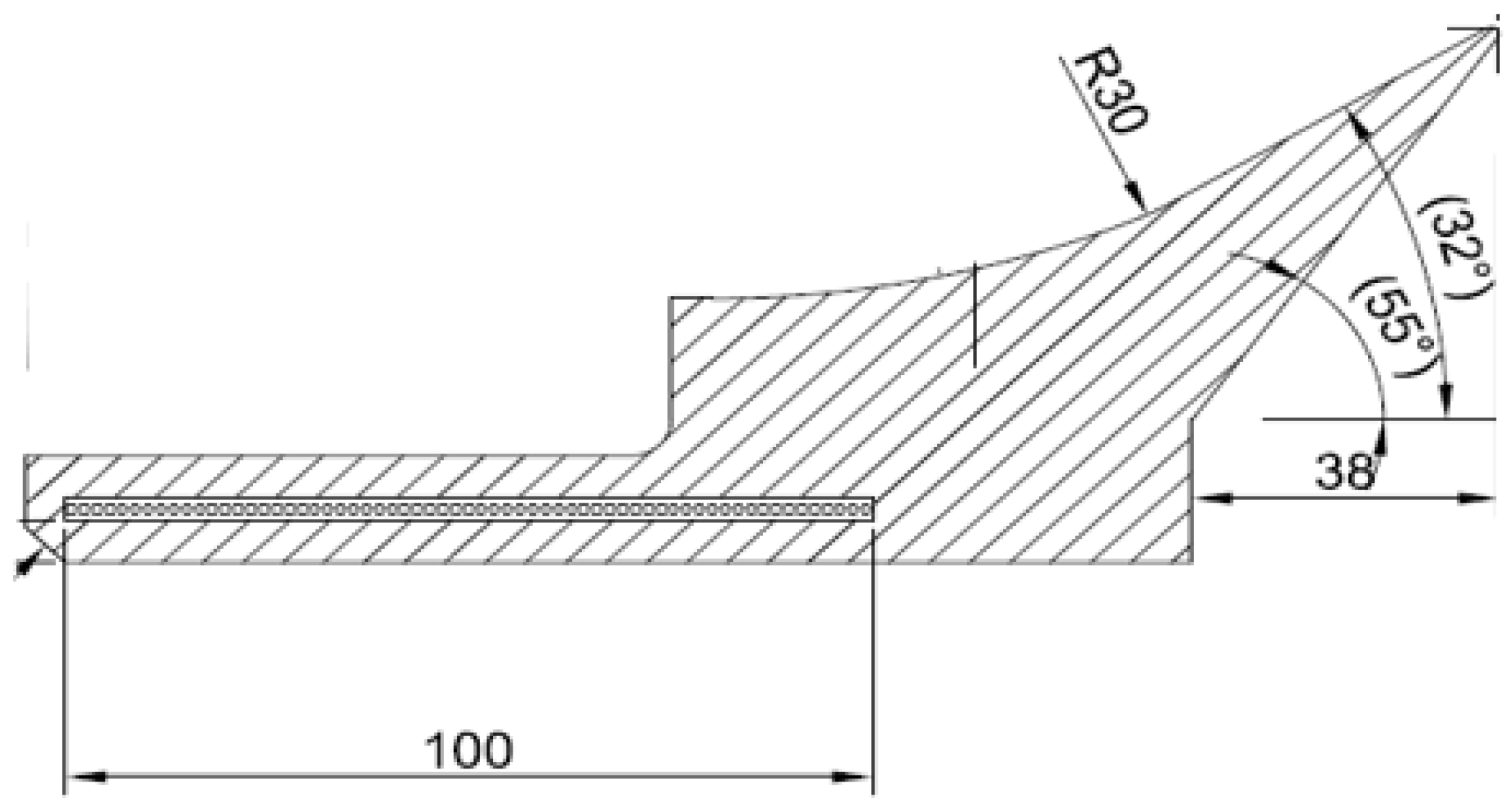
The design of a suction pad for an automatic mooring device incorporates various factors, including the mooring force exerted by the target ship (specifically, sway and surge forces), material composition, and shape of the rubber seal [6]. The size of the suction pad is calculated based on the magnitude of the mooring force exerted on the target ship. This estimation considers different loads, such as wind, current, and wave forces, under specific environmental conditions. Empirical and numerical analytical methods are typically used for this estimation. The selection of the rubber seal material is crucial for withstanding the forces exerted by the ship, considering factors such as heat resistance, pressure resistance, and weather resistance. The objective is to minimize the potential damage and corrosion of the ship’s hull. The shape of the lip and the contact angle of the rubber seal are essential design variables because they directly interact with the hull of the ship. The design process focuses on optimizing these aspects to achieve efficient performance by determining the most suitable lip shape and contact angle.
Significant prior research has been conducted on the development of safe and efficient ship mooring methods and automatic mooring systems. In Korea, efforts have been made to develop automatic systems for ship-to-ship docking [7]. Empirical studies have also been conducted to design a sliding mode control system for automatic mooring between ships and ports [8]. Seo and Oh [9] conducted research to estimate the mooring force applied to the training ship HANBADA, adhering to the design standards for ports and fishing ports. In a separate study, Son et al. [10] investigated and analyzed the changes in the mechanical properties of materials suitable for rubber seals used in vacuum-type automatic mooring systems in response to temperature fluctuations. In international studies, an innovative design has been proposed to replace the traditional single-rope mode with a dual-rope parallel mode that maintains high tensile strength and low effective spring constants in the ropes. This design has been verified to reduce momentary tension and increase the safety factor of the ropes [11]. Additionally, a research and development effort has been focused on an intelligent mooring system based on ship hydrodynamics, mechanism kinetics, and intelligent algorithms, yielding effective suppression of mooring line movements under various operational conditions [12]. In previous studies, novel mooring methods have been proposed from a stability perspective. Additionally, research has been conducted on ship motion control, estimation of mooring forces for suction, and the selection and design of rubber seal materials to prevent system damage for the development of automatic mooring devices. However, there has been a lack of research on the performance testing of the suction pads applied in the automatic mooring system.
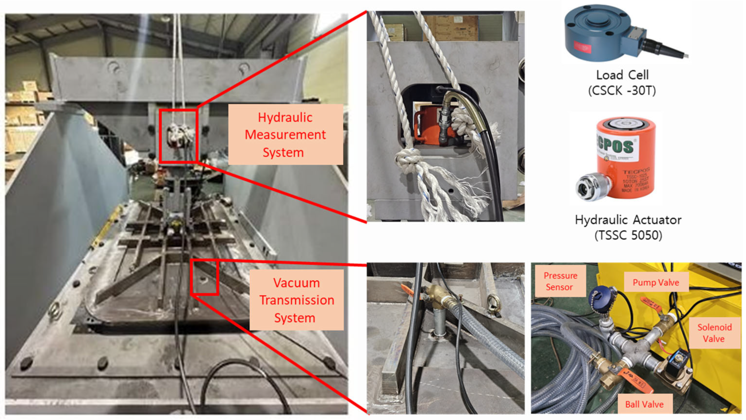
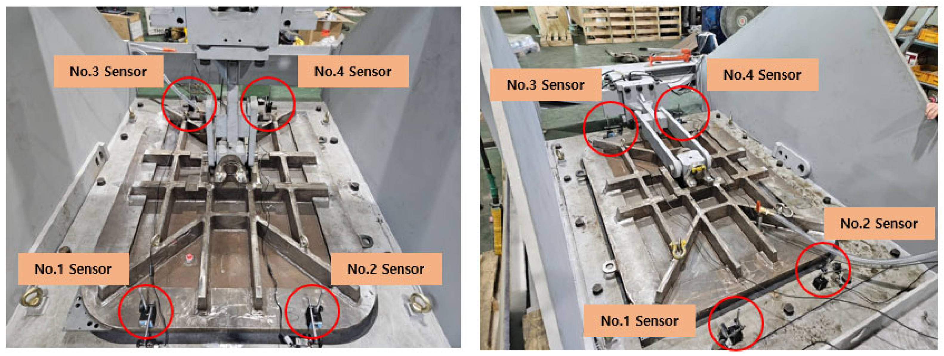
This study investigated the design requirements for future smart port construction in Korea and assessed the performance of automatic mooring systems through real-scale testing. To determine the target suction force for the automatic mooring device, the longitudinal (Fx) and transverse (Fy) mooring forces were estimated based on established design standards for ports and fishing ports. The suction method (vacuum or magnetic) and pad type (single pad or double pad) were selected considering the prevailing environmental conditions and port infrastructure. The suction pad utilizes a thermoplastic elastomer rubber seal known for its outstanding properties, including ozone resistance, weather resistance, flame retardancy, and strong adhesion to metals and plastics. Natural rubber (NR) with a high tensile strength and excellent mechanical properties was chosen as the material for the rubber seal. The design of the rubber seal focused on maximizing the contact area between the hull and pad while preventing the rubber from drying, with special attention paid to the lip area and contact angle. For the real-scale test, equipment was developed to evaluate the performance of the automatic mooring device. The experimental results were compared with the theoretically calculated suction forces, and the displacement of the rubber suction pad was measured under the maximum mooring force. Moreover, the ability of the ship to withstand the maximum mooring force in the surge and sway directions under various environmental conditions was assessed to ensure an accurate reflection of real-world scenarios.
In this study, the design and performance testing of vacuum suction pads for the development of an automatic mooring system could hold significant implications for various future research domains. It could aid in securing the feasibility of LiDAR visual sensor system development for assessing ship docking conditions [13]. By utilizing the vacuum change and displacement data obtained in this study, we can develop the capacity to proactively detect situations such as improper object adhesion or slipping during movement, thus preventing accidents during operations. Consequently, it introduces novel suggestions to address the challenge of when harbor workers and passengers should evacuate or abandon the ship [14]. Additionally, leveraging the mentioned data, the PID controller can proficiently regulate the force of hydraulic actuators, thereby contributing to effectively managing ship motion within desired ranges, not only under environmental disturbances but also in other scenarios [15]. This way, the study contributes to enhancing maritime technology and its applications.
In this way, this study presents a significant approach to advancing maritime technology, despite certain limitations and assumptions. It accomplishes this by introducing an innovative vacuum suction pad design and a comprehensive performance testing methodology, thereby offering a crucial avenue for the advancement of oceanic technology. Moreover, it models the future of automatic mooring systems and their integration into smart port environments.

2. HANBADA Ship’s Mooring Force Estimation

2.1. Target Ship

Figure 2 depicts the mooring process of HANBADA, which is a training ship measuring 104 m in length overall (LOA). It falls under the 6600-ton ship category and is specifically designed to accommodate future demonstrations. Additional information regarding the ship is provided in Table 1.

2.2. Estimation of the Mooring Force on the HANBADA Ship

When designing a mooring system for a ship, it is crucial to consider the various loads that the ship encounters while docking at port. These loads include the wind force, fluid force from the current, and fluid force from waves. In this study, the port selected for analysis was the pier at the Korea Maritime and Ocean University. The port has a depth of approximately 6–7 m, and the tide in the vicinity is influenced by illumination, resulting in a dampened effect compared with the main tide in the port. The tide flows toward the inner port through the illuminated area [17]. As shown in Figure 3, the ship “HANBADA” is moored at the pier of Korea Maritime and Ocean University. The direction of the mooring force was determined by calculating the loads acting on the ship in the most significant longitudinal direction (Fx) and lateral direction (Fy) based on the ship’s central axis.

2.3. Estimation of the Mooring Force Due to Wind

The wind force acting on a moored ship is determined by considering the forces in the Fx and Fy directions, which account for the variations in the wind speed and the hull cross-sectional shape. The wind force in the Fx direction primarily affected the frontal projection area of the upper part of the water surface, resulting in a relatively smaller force. Conversely, wind from the Fy direction acts on the transverse projection area of the upper part of the water surface, leading to a significantly larger force. Typically, wind force is calculated assuming a specific wind speed distribution, such as an exponential distribution, based on sea wind characteristics in the port area. However, in this study, a conservative approach was adopted by assuming a uniform flow. Considering the sea area of the port and the avoidance of wind speeds up to beafort 7, the maximum wind speed for the port was set to 14 m/s, corresponding to beafort 6. Ideally, the wind pressure coefficients (Cx, Cx, Cy and CM) should be obtained through wind tunnel experiments or water tank tests specific to the ship under consideration. However, these experiments are time-consuming and expensive. Therefore, in this study, the wind pressure coefficient was calculated using computational fluid dynamics (CFD) values derived by Sea and Oh [9], and Equations (1)–(3) from the port and fishing port design standards provided by the Ministry of Ocean and Fisheries [18] were employed.
R x = 1 2 ρ a U 2 A r C x
R y = 1 2 ρ a U 2 A L C y
R M = 1 2 ρ a U 2 A L L p p C M
Cx: x-direction wind drag coefficient.
Cy: y-direction wind drag coefficient.
CM: Wind pressure moment coefficient at the ship center.
Rx: Sum of x-direction component of wind force (kN).
Ry: Sum of y-direction component of wind force (kN).
RM: Moment of rotation of the ship’s central axis of the combined wind force (kN·m).
ρ a : Density of air (kg/m3).
Ar: Transverse projected area (m2).
AL: Lateral projected area (m2).
LPP: Length between perpendiculars.

2.4. Estimation of the Mooring Force Due to Current

The fluid force generated by the current can be divided into friction and pressure resistance components. The friction resistance is more significant in the flow direction, whereas the pressure resistance is dominant in the lateral flow direction. However, accurately separating the friction resistance from the pressure resistance is challenging because of their interconnected nature. In the case of the Korea Maritime and Ocean University Port, located near the entrance of Busan Port, the current speed was determined to be 0.5 knots with a direction of 030°. The fluid pressure resulting from the current can be calculated using Equation (4), provided by the Ministry of Oceans and Fisheries [18].
R f = ρ w g λ 1 + 0.0043 15 t } S V 1.825
R f : Fluid pressure (kN).
ρ w : The specific gravity of sea water (≒1.03 ton/m3).
g : Gravitational acceleration.
t : Temperature (°C) (≒15 °C).
S : Submerged surface area (m2).
V : Flow rate (m/s).
λ : Coefficient (≒0.14).

2.5. Estimation of the Mooring Force Due to Waves

The calculation of the wave force acting on a moored ship requires an appropriate method that considers the shape of the ship and wave specifications based on port and fishing port design standards. An accurate calculation of the wave force can be performed through model tests, CFD, and kinematic analyses. However, in this study, the wavelength of the sea area was relatively large (0.5 m); therefore, the strip method was used for the calculation. The wavelength of the port, on the other hand, was not significant at 0.5 m, and was therefore disregarded in this study [9].

2.6. Total Mooring Force of the HANBADA Ship

Table 2 presents the forces that can occur when the 6400-ton HANBADA moors at the pier of the Korea Maritime and Ocean University under specific environmental conditions. The wind speed is 14 m/s, the current flows at 0.5 knots, and there are waves with a height of 0.5 m and a period of 8.3 s. The projection area was relatively small in the longitudinal direction of the ship and the effect of the current was insignificant, resulting in a force of approximately 17.7 kN. However, in the lateral direction, a substantial force of 248 kN was generated because of the larger lateral projection area caused by the superstructure of the ship.
Furthermore, based on the installation case of CAVOTEC, if a specific technology is not applied, most installations have a capacity of less than 400 kN (200 kN for 1, 200 kN for 2, and 400 kN for 1) based on the sway. To calculate the target suction force, least-squares curve fitting was employed using the CAVOTEC’s ship length specification data to derive the expected mooring force for the ship being tested in comparison with the LOA. A comparative verification was performed using the values calculated from the empirical formula. When comparing all ship types, considering data from a relatively challenging environment (port without a breakwater), an excessive suction force may be calculated, and application specifications can vary depending on the ship type. Therefore, it was deemed appropriate to use data that compared only the Ferry and Ro-Ro lines, which are similar in length to HANBADA. The estimated expected mooring force is shown in Figure 4.
The expected performance may vary depending on the order of the selected curves. However, for the data selected based on the Ferry and Ro-Ro lengths, a mooring force of approximately 600 kN was required. In addition, the lateral (sway) force under extreme oceanic conditions (Beaufort 6) was estimated to have a maximum mooring force of 248 kN. Therefore, the target suction force was calculated as the maximum mooring force of approximately 200 kN per suction pad, and it is expected that two to three automatic mooring devices will be required to moor the training ship HANBADA. Furthermore, upon reviewing the data from all ships, it is evident that the mooring forces exceed 900 kN. Given the approximately 46% difference between the Ferry and Ro-Ro data, it becomes essential to consider the feasibility of suction for large ships when applying the automatic mooring system.

3. Vacuum Suction Pad’s Design Requirements

3.1. Suction Modes

There are two methods for generating suction force in a suction pad: vacuum and magnetic suction. Magnetic suction pads require a power supply for the magnet and can potentially damage the hull during mooring [19]. In contrast, vacuum-based suction pads do not damage the hull, and once a ship is stably moored, power is not required to maintain the suction force [20]. Therefore, a suction pad was selected for the vacuum method for the automatic mooring device developed in this study.

3.2. Single Pad/Double Pad

The selection of single- or double-pad configurations in automatic mooring systems depends on specific requirements related to environmental conditions and port infrastructure. Single pads offer the advantage of easy replacement in the case of damage and provide control over the ship using a tension adjustment line and a winch. However, they have limitations in responding to suction in both surge and sway directions in the event of a primary failure. In addition, a strong mooring force can reduce the lifespan of the rubber seals. In general, single pads are used for smaller ships when there are space or infrastructure constraints on the port. In contrast, double pads are designed to distribute the mooring force by increasing the suction force, which improves safety and control. They can effectively respond to suction in both the bow and stern areas. However, the use of double pads requires a larger vacuum pump because of the increased surface area.
Considering the infrastructure and environmental conditions of the new port in Busan, which is being developed as a smart port in Korea, Busan is an ideal location for installing the automatic mooring device developed in this study. The new port, known as the break water, spans a length of 14.71 km. It is equipped with state-of-the-art facilities, including reprocessing facilities and automated docks, to facilitate efficient cargo processing, ship operations, and logistics. Port infrastructure provides a conducive environment for the implementation of an automatic mooring system. In terms of environmental conditions, the waters near Busan Port experience seasonally variable average wave directions. Although the significant wave height is not strictly seasonal, the maximum recorded significant wave height was 7.4 m during Typhoon Cicada in September 2003 [21]. Given these conditions, the use of double pads to accommodate large cargo ships and withstand challenging environmental conditions will enhance port logistics efficiency and ensure safe ship mooring.

3.3. Vacuum Suction Pad’s Specifications

The MoorMaster model developed by CAVOTEC in Switzerland was selected as the target reference model for the automatic mooring device. This reference model used a vacuum-based mooring method to secure a ship while docking at a port. The vacuum suction pad specifications included a width of 1.91 m and length of 1.40 m for a single-pad configuration. It was designed to provide a suction capacity of 200 kN in the sway direction and 100 kN in the surge direction, with a suction time of 30 s, a desorption time of 15 s, and a vacuum pressure of −80 kPa. The detailed specifications are listed in Table 3.
In a previous study conducted by Son et al. [10], during a lab-scale test, the vacuum applied to the suction pad was reduced by 80%. This reduction resulted in a decrease in height by 39 mm compared with the existing suction pad. Furthermore, it was determined that a point within 60 mm of each pad length would be considered within the normal range for usage.
To ensure high differentiation and improved suction performance compared with the previous company, Figure 5 illustrates the modifications made. The suction area between the hull and pad was maximized by increasing the total dimensions by 60 mm from the existing COVOTEC’s MoorMaster suction pad specifications (1.4 m × 1.91 m). The revised specifications for the suction pad in the real-scale test were calculated to be 1.95 m wide and 1.38 m long, resulting in a vacuum suction area of 2.27 m2 and a suction force of 181.6 kN. This represents an increase of approximately 2.6% compared with the specifications of the previous company.

3.4. Selection of Rubber Seal Material

Rubber materials have extensive applications in supporting loads, absorbing vibrations and shocks, and preventing air or fluid leakage because of their ability to undergo significant deformation even under low loads [23]. For effective ship mooring, maintaining the integrity of the vacuum seal between the hull and rubber seal is crucial to ensure proper suction [24]. The rubber seal used in the suction pad should possess maximum rigidity to withstand mooring forces, minimize damage to the outer surface of the hull, and be lightweight and corrosion resistant. Therefore, this study presents the physical properties of five representative rubber materials, listed in Table 4, to facilitate the selection of appropriate rubber seal materials.
When examining the properties of each rubber type, neoprene rubber (CR) demonstrated excellent characteristics, such as weather, ozone, heat, chemical, and aging resistance. Nitrile rubber (NBR) exhibits exceptional oil resistance, wear resistance, and aging resistance, whereas silicon rubber (VMQ) exhibits high heat resistance, cold resistance, non-toxicity, oil resistance, and weather resistance. Ethylene-propylene rubber (EPDM) shows good aging resistance, ozone resistance, resistance to polar liquids, and favorable electrical properties. Unlike NBR, hydrogenated nitrile rubber (HNBR) exhibits excellent weather resistance, ozone resistance, and mechanical strength. The rubber seal employed in this study must ensure safety to prevent the drying and damage of rubber when in contact with the ship pad. Consequently, natural rubber (NR) [25], which is renowned for its high tensile strength and excellent mechanical properties, was used with a small amount of CR material, which exhibits superior adhesion properties including ozone resistance to metals and plastics, to prevent performance degradation. The details of the rubber seal materials are listed in Table 5.

3.5. Rubber Seal Design

The performance of the vacuum suction pad in an automatic mooring device is determined by the rubber seal. Maintaining an appropriate vacuum state during hull suction is crucial for withstanding the mooring force for ship fixation. Therefore, the shape of the rubber seal was optimized for it to function effectively without excessive mechanical deformation or damage [26]. The rubber seal cross-section patented by CAVOTEC demonstrates an extrusion packing form, whereas Figure 6 illustrates the cross-sectional view of the rubber seal installed on the vacuum suction pad in this study. The lip area, which comes in contact with the hull, and the contact angle serve as important design variables for ensuring superior performance and stable suction. Therefore, the focus of the design was to maximize the contact area by setting the contact angle to 32° to prevent the rubber from drying. Additionally, a shim plate was inserted within the cross-section to prevent a decrease in suction force and seal damage, as the contact area with the hull reduced while it was in the adsorbed state due to ship movement.

4. Real-Scale Performance of the Vacuum Suction Pad

4.1. Real-Scale Test Equipment

The test jig equipment used for the performance testing of the vacuum suction pad in this study had a total length of 3.7 m, a width of 2.2 m, and a height of 1.9 m. As shown in Figure 7, the equipment side and jig were bolted together to allow separation and testing in the surge and sway directions. Additional steel plates were secured on the top of the floor to withstand external forces of up to 200 kN during the test, which could potentially damage the equipment. The instrument design, as described in Section 3, incorporated a cross-shaft to accommodate and respond to the curved surface of the ship’s bow. The jig and pad were attached, and a ±10° spring was installed within the allowable range to mitigate the force transmitted to the instrument part, as shown in Figure 8.

4.2. Vacuum and Hydraulic Transmission System

The vacuum and hydraulic transfer systems used in the scale-performance tests are shown in Figure 9. For the vacuum delivery system, a dry claw pump model C-VLR 100 was employed, providing a vacuum exhaust capacity of 100–150 m3/h and achieving a final vacuum of 100–150 mbar during continuous operation. The vacuum pump was driven by a separate hydraulic driver and the vacuum level was monitored using a pressure sensor connected to the pipeline. When the vacuum reached −80 kPa, the ball valve was opened, allowing the vacuum to be transmitted to the suction pad. The pressure sensor used in this setup is the MS-P200 model, capable of measuring gauge pressure ranging from 0.06 to 35 kgf/L. When detachment is required, the vacuum can be released through the solenoid valve.
The hydraulic transmission system comprises a hydraulic actuator for lifting the pad and a load cell for measuring the load. The hydraulic actuator used in the test was connected to a jig to facilitate pad lifting. A TSSC 5050 model capable of providing a maximum load of 50 t was employed. It is advantageous for use in compact spaces and is user-friendly. The load cell used was the CSCK-30T model, which was constructed from high-strength alloy steel to prevent damage upon contact with the piston. When hydraulic pressure is applied to the actuator, the piston rises because of the compression spring installed inside, and the load is measured using a load cell on the upper surface.
The data collection process involves digitizing the analog input data using NI’s multifunctional data acquisition module, specifically the NI USB-6363. The sampling rate was set at 100 Hz to ensure accurate data collection.

4.3. Displacement Measurement

As previously mentioned, the vacuum suction pad operates by creating differential pressure between the internal and external environments, which results in a strong bond with the surface. The rubber material used in the pad is flexible and deformable, allowing it to maintain its shape while in contact with its surface. The effectiveness of the seal and overall performance of the vacuum suction pad was evaluated by measuring the displacement of rubber during the suction process. The excessive displacement or deformation of rubber may indicate potential leakage points or inadequate suction, compromising its effectiveness. Autonics BD-65 model sensors were used to measure the displacement. The sensor has a maximum measurement range of 65 mm. Four displacement sensors were installed during the sway and surge tests as shown in Figure 10. Prior to installing the sensors, the pad was positioned horizontally using a level meter, and each of the four sensors was fixed at the same position on a flat surface. The sensor-fixing device has a magnet at the bottom, which facilitates easy installation.
For the sway state, the laser sensor was directed toward the bottom surface, and the sensors were installed at 300 mm intervals starting from the center of the pad’s longitudinal length (1400 mm). In the surge state, the laser was positioned on the floor and reflected onto a steel plate attached to the upper surface of the rubber seal. The sensor spacing in the surge state was identical to that in the sway state. Displacement data were collected simultaneously with vacuum and load measurements using data acquisition (DAQ) equipment.

4.4. Evaluation Criteria Table of the Real-Scale Test

To ensure the accuracy of the performance evaluation of the vacuum suction pad, leakage tests were conducted on the components that could potentially leak in a vacuum state, including ball valves, vacuum tube lines, and suction pads. The rubber seal was pressed onto a steel plate, and the vacuum pump was operated to reach a pressure level of −80 kPa, as indicated by the pressure gauge. Leakage tests were conducted on each component. The ball valve was closed to observe any pressure changes and check for leakage. For the leakage test of the vacuum tube line, the pressure change was measured while the vacuum tube line valve was locked, and the ball valve remained open. Finally, leakage through the suction pad was evaluated after opening all the valves.
Spring washers were used between the rubber seal and the inner mounting plate to minimize air leakage at the bolt joints. For the real-scale performance test, the evaluation was designed to replicate actual ship mooring conditions and environmental factors. Under flat, dry conditions with no surface obstructions, a maximum mooring force of 200 kN was applied in the sway direction as a static load. The load was maintained at 180 kN. In the surge direction, a 90 kN load was applied to assess whether the suction force and vacuum were maintained for 30 min. Furthermore, considering the effects of radiation and beafort 6 environmental conditions generated during ship operations, the test confirmed the ability of the hull to withstand the maximum suction force when the surface was smooth. The test was also conducted under water spray conditions, with water sprayed on the floor, lip contact area, and inside the pad, as shown in Figure 11. The evaluation items for the real-scale test are presented in Table 6.

5. Experimental Results

5.1. Leakage Test

Figure 12 presents the results of the 30 min leak test conducted on each component. The vertical axis represents the vacuum ratio, which is expressed as the ratio of the vacuum pressure (P) measured during the test to the initial vacuum pressure (Pi) measured during the leakage test. To indicate the extent of leakage, the vacuum ratio (P/Pi) was plotted over time for the three components. The results of the leakage test indicate that the vacuum ratio remained within the range of 0.9 to 1.0 for all three components, and the vacuum was sustained for the entire 30 min duration. Therefore, it can be concluded that no air leakage occurred during the tests.

5.2. Sway Test (Vertical Suction Performance Evaluation)

Figure 13 shows the load, vacuum pressure, and displacement values measured for 30 min in the sway state under dry and water spray conditions. Examining the load and vacuum ratio under both conditions, it was observed that the vacuum ratio remains at 1.0 even after applying loads of 200–180 kN under dry conditions. However, under the water spray condition, the vacuum ratio increased slightly to 1.03 due to the load. This increase can be attributed to the volume expansion caused by moisture evaporation within the pad, which results in an increase in the internal pressure. Nevertheless, the vacuum ratio (1.03) was within the acceptable range for maintaining the suction force. Regarding the displacement measurements in the sway state, the No. 2 displacement sensor, located near the vacuum pipe connected to the pad, exhibited more vibrations compared to other sensors. Consequently, the measurements from this sensor were excluded from the analysis. Under dry conditions, the displacement ranged from 11 mm to 16 mm with a 200 kN load. Although there were slight variations (1–3 mm) among the displacement sensor measurements compared to the average, they were deemed acceptable. In contrast, the water spray condition exhibited more uniform displacement values than the dry condition. The average displacement was 6 mm smaller, indicating a higher vacuum ratio of 1.03 and a smaller displacement owing to increased suction. Visual inspections confirmed that there was no drying or damage to the rubber seal during the test and that the suction force could be maintained under a maximum load of 200 kN, as depicted in Figure 14.

5.3. Surge Test (Horizontal Suction Performance Evaluation)

Figure 15 illustrates the load, vacuum pressure, and displacement values measured for 30 min in the surge state under both dry and water spray conditions. In the surge test, when a load of 90 kN was applied, the vacuum ratio decreased to 0.99, indicating a potential leakage during the test. This leak is believed to have occurred because of the friction force between the ground and suction pad, which differs from the sway test. However, under both dry and water spray conditions, the vacuum ratio remained constant even after the load was applied. Under dry conditions, the displacement measurements exhibited uniform values up to 20 mm for all the four displacement sensors, corresponding to the maximum suction force. However, under the water spray condition, the displacement increased by more than 50 mm, while a constant load was maintained. This increase in displacement can be attributed to the friction force, which was not affected by dry conditions when the surface was smooth. The displacement continued to increase even after 30 min of testing. While the dry condition maintained suction at a vacuum pressure of −80 kPa, the water spray condition required a higher vacuum pressure. Therefore, further tests under various vacuum pressures are required. Figure 16 shows that a minor leak occurred during the surge test. However, as in the sway test, no drying or damage to the rubber seal was observed.

5.4. Rubber Seal Elasticity Recovery Test

In the surge test, there is a possibility of leakage owing to ground friction, which can result in a slight deformation of the rubber seal. Therefore, whether displacement will recover to its initial position after removing the load in a surge situation must be determined. Figure 17 shows the displacement values for 10 min after the load was removed during the surge test. The rubber seal recovered to 5 mm less than the initial position once the load was removed. Although some deformation occurred, it was deemed to be within an acceptable range. However, because of the characteristics of rubber, the Mullins effect, which involves an increase in the cross-sectional area, can occur when a continuous load is applied. Therefore, additional tests are necessary to confirm the performance of rubber seals.

6. Conclusions

In this study, the design elements required for a vacuum suction pad applied to an automatic mooring device in preparation for the construction of a smart port in Korea were identified. Rubber materials were selected, and rubber seals were designed and manufactured. A real-scale performance test was conducted to evaluate the vacuum ratio and displacement values and assess the pad’s ability to withstand the maximum mooring force.
The maximum mooring force of the HANBADA training ship at the Korea Maritime and Ocean University was calculated based on empirical formulas. In the sway direction, which is the longitudinal direction of the ship, a force of approximately 17.7 kN was estimated owing to the smaller projection area and weaker tides. However, in the surge direction, a mooring force of 248 kN was estimated, owing to the larger lateral projection area caused by the superstructure of the ship. Based on the least-squares curve, fitting was applied to the CAVOTEC’s ship length specification data, and a mooring force of approximately 600 kN was determined for the Ferry and Ro-Ro ships. Considering these factors, it was concluded that a maximum suction force of 200 kN per unit and a double-pad type would ensure stable mooring. The specifications of the vacuum suction pad were modified to increase the dimensions by 60 mm compared to the COVOTEC pad specifications. This maximized the suction area of the hull and pad, resulting in an increased suction force of 181.6 kN, which was approximately 2.6% higher than that of the previous model. The selection and design of rubber seal materials involved the addition of NR with excellent mechanical properties and a small amount of CR material for ozone resistance to prevent performance degradation.
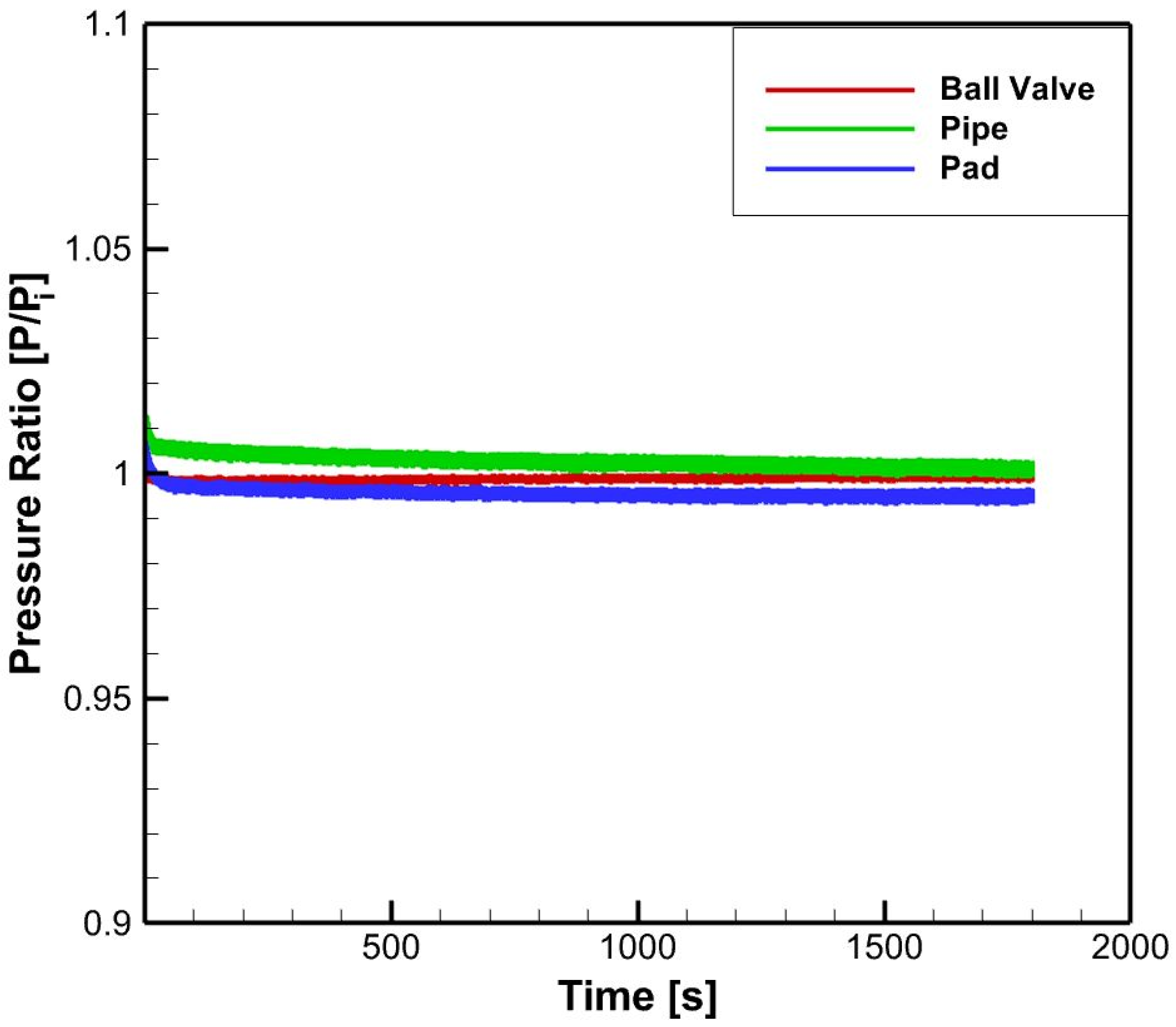
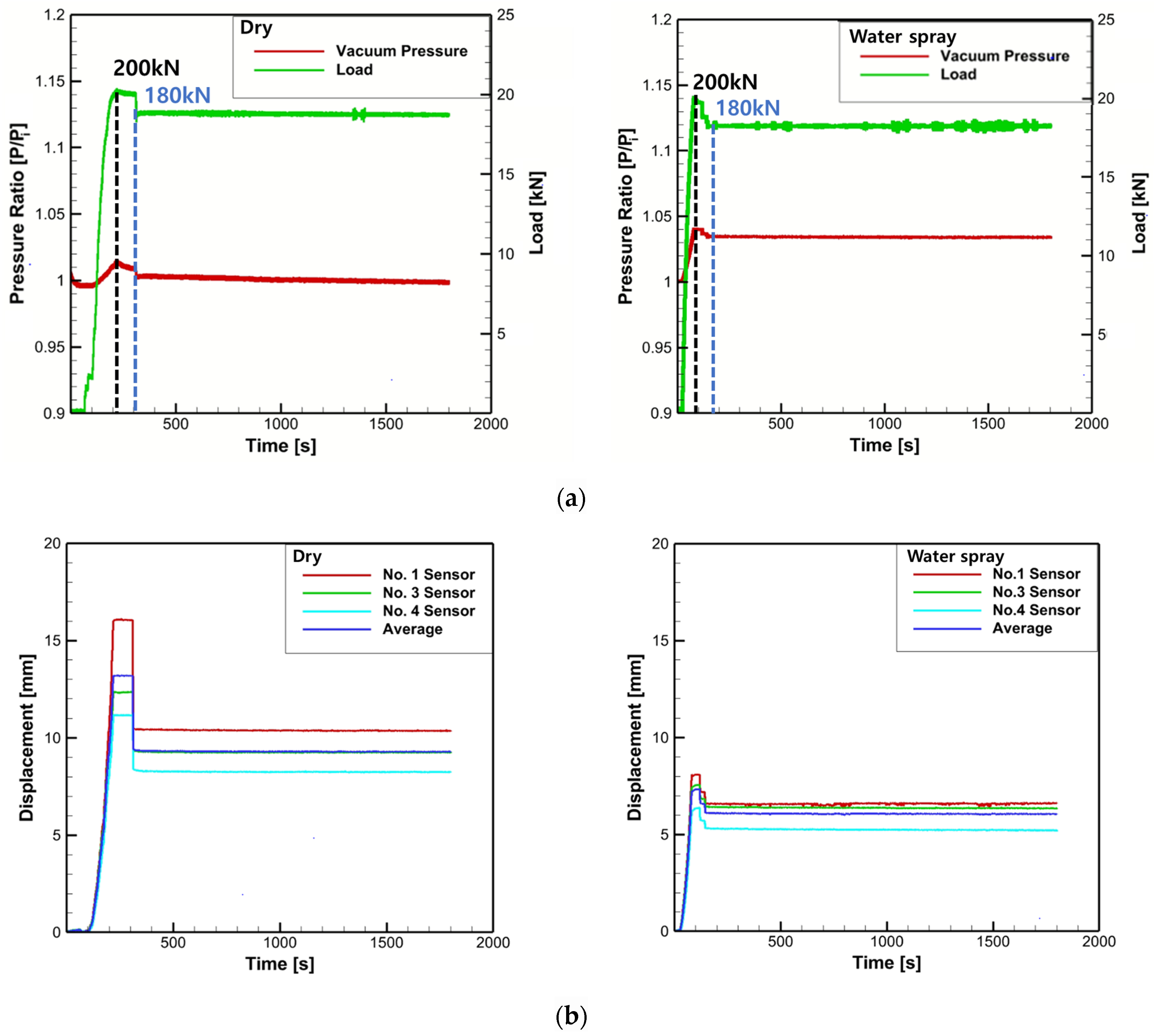
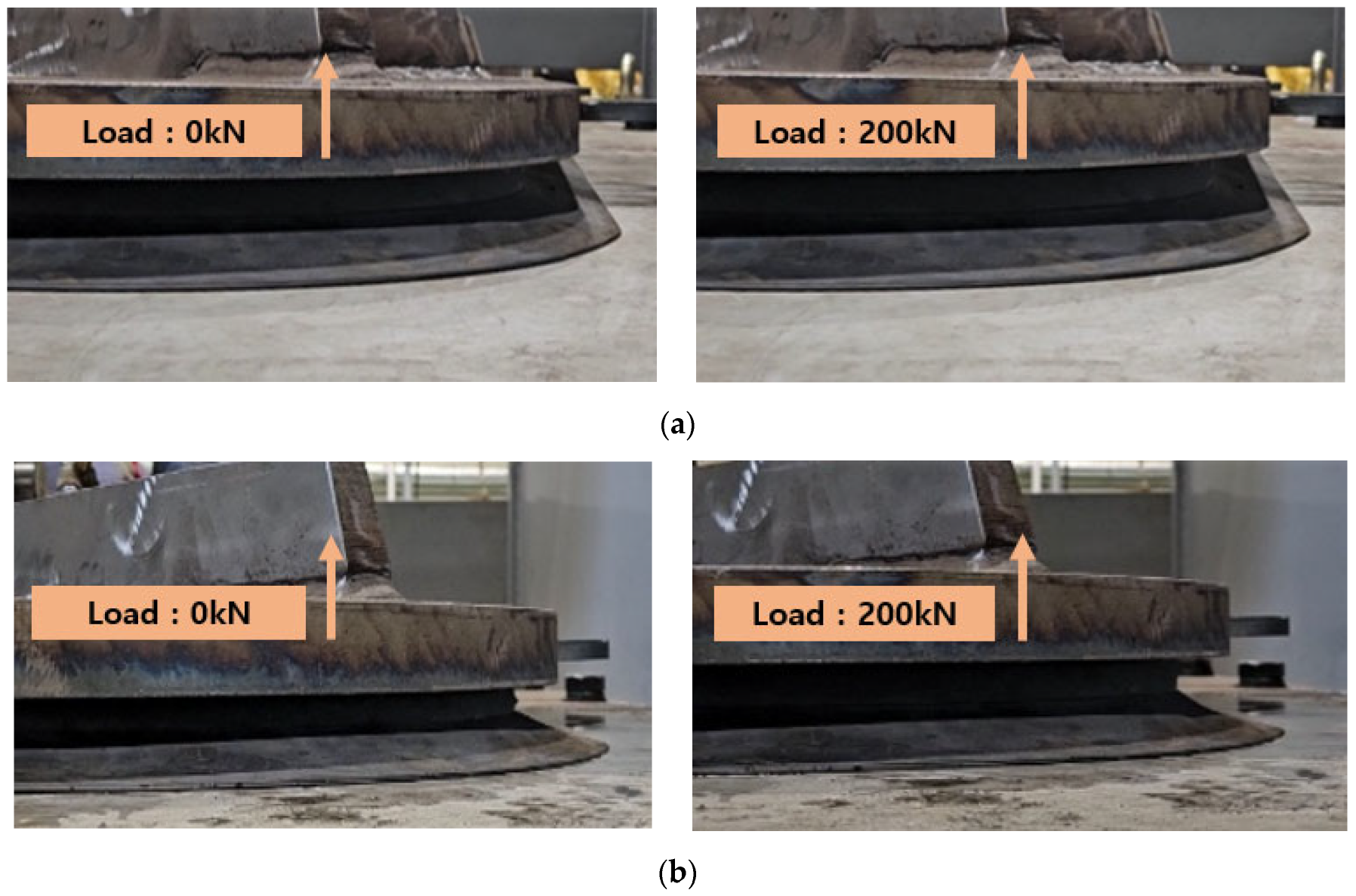
The real-scale performance tests included leakage, sway, and water spray tests in the surge direction. The leakage test confirmed that no air leakage occurred and that the vacuum pressure remained constant. In the sway test, vacuum was maintained even under a maximum load of 200 kN under dry conditions with a vacuum pressure of −80 kPa. Under the water spray condition, the vacuum ratio increased slightly to 1.03; however, the suction force was maintained. In the surge direction, under both dry and water spray conditions, the vacuum ratio decreased to 0.99, indicating slight air leakage in the pad owing to ground friction.
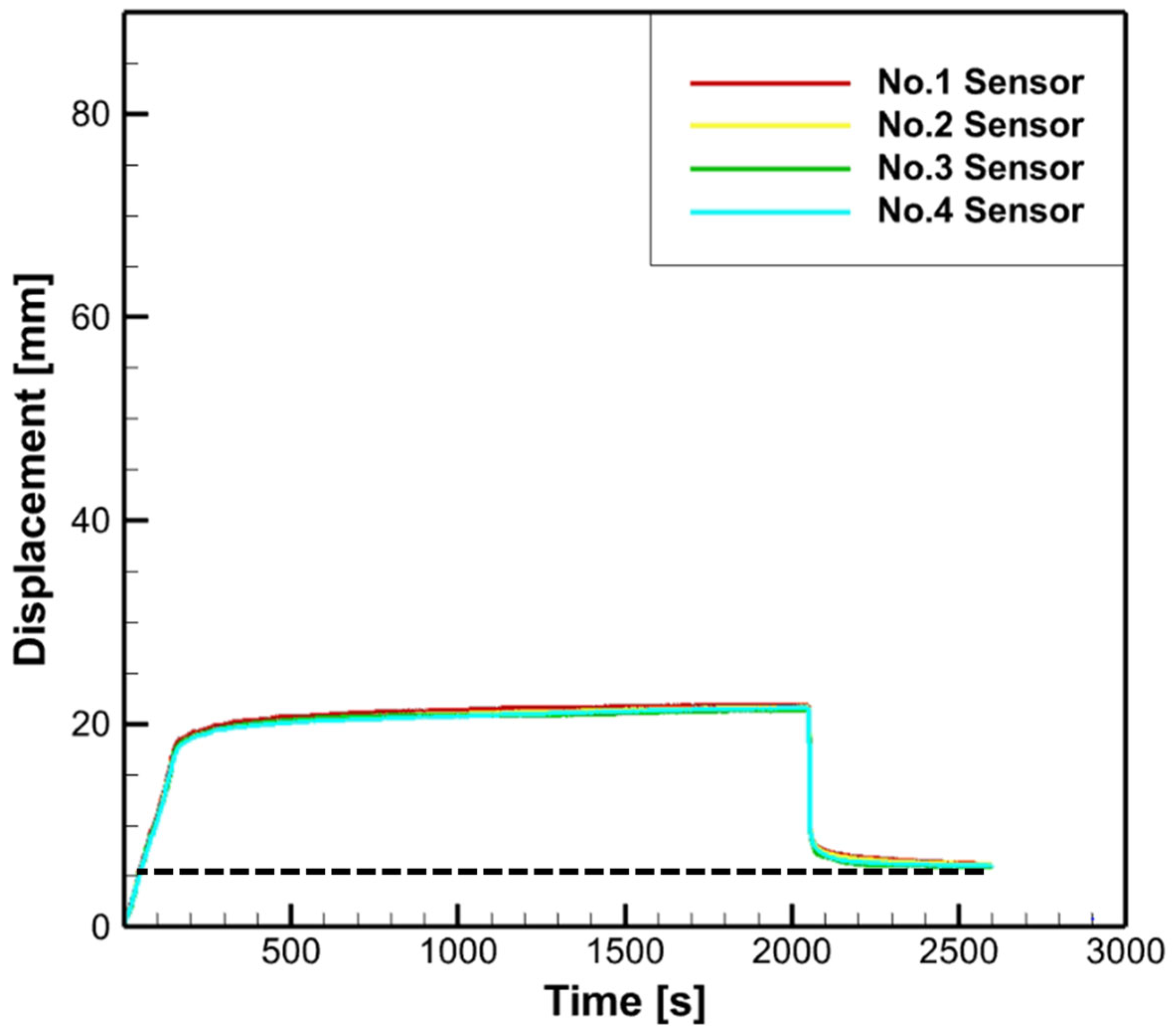
Displacement measurements were conducted using a laser sensor to observe the changes in the shape of the rubber seal when a load was applied and subsequently removed. In the sway state, there was a difference of 1–3 mm compared with the average displacement, whereas the water spray condition showed a more uniform displacement, measuring 3 mm less than the average displacement under dry conditions. In the surge state, the displacement reached 20 mm under dry conditions and 50 mm under water spray conditions; however, no drying or damage to the rubber seal was observed.
In future studies, furthermore, this paper estimated mooring forces based on a 6400-ton HANBADA ship. However, there are plans to expand the research by selecting various types of ships, such as large container ships (KCS), tanker ships (KVLCC2), and cargo ships (JBC). These plans also include calculating mooring forces considering different harbor environmental conditions and conducting suction performance tests.
The suction performance test is planned to be conducted under conditions where welding lines and anti-fouling coatings are applied, simulating the hull environment. This test will consider the suction situation in areas of the hull with curvature, as well as on inclined surfaces, where the bottom surface is slanted, and further tests will be performed to determine the required range of vacuum pressure and load considering the water spray conditions and elastic recovery of the rubber.

Author Contributions

Conceptualization, D.S. and H.J.; methodology, Y.K. and J.A.; data curation, J.A., Y.K. and J.L.; investigation, J.A.; writing—original draft, J.A. and Y.K.; writing—review and editing, T.L. and J.O.; supervision, H.J. and D.S.; funding acquisition, Y.K., D.S. and H.J. All authors have read and agreed to the published version of the manuscript.

Funding

This research was supported by Korea Institute of Marine Science & Technology Promotion (KIMST) funded by the Ministry of Oceans and Fisheries, Korea (No. 20210631).

Institutional Review Board Statement

Not applicable.

Informed Consent Statement

Not applicable.

Data Availability Statement

Not applicable.

Acknowledgments

This article paper was a part of the project titled “Development of Smart Port Autonomous Ships Linkage Technology”, funded by the Ministry of Oceans and Fisheries, Korea (No. 20210631).

Conflicts of Interest

The authors declare no conflict of interest. The funders had no role in the design of the study, in the collection, analyses, or interpretation of data, in the writing of the manuscript, or in the decision to publish the results.

References

  1. Ministry of Oceans and Fisheries. Smart Port Technology Industry Promotion and Market Expansion Strategy; Ministry of Oceans and Fisheries Press Release, 2023; Available online: https://www.mof.go.kr/doc/ko/selectDoc.do?menuSeq=971&bbsSeq=10&docSeq=48733 (accessed on 24 May 2023).
  2. Chung, T.W. Advanced Case Analysis, and Implications of a Smart Seaport. J. Ship. Logist. 2018, 34, 489–510. [Google Scholar] [CrossRef]
  3. Choi, S.H. Smart Port Logistics Technology Leading the Future. J. Korea Inst. Electron. Eng. 2012, 39, 39–46. [Google Scholar]
  4. Lee, T.W. Smart Port Policy Trend of Europe and Singapore and Its Political Implications. J. Korea Port Econ. Assoc. 2020, 36, 77–89. [Google Scholar] [CrossRef]
  5. Yan, K.; Zhang, S.; Oh, J.; Seo, D.-W. A Review of Progress and Applications of Automated Vacuum Mooring Systems. J. Mar. Sci. Eng. 2022, 10, 1085. [Google Scholar] [CrossRef]
  6. Schneider, R.T. Designing with Vacuum and Suction Cups. WWW Document. 2006. Available online: https://www.powermotiontech.com/pneumatics/vacuumtechnology/article/21881814/designing-with-vacuum-and-suction-cups (accessed on 9 January 2022).
  7. Lee, Y.S.; Jeong, T.G.; Jung, C.H.; Kim, S.W. Conceptual Design for Mooring Stability System and Equipments of Mobile Harbor. J. Navig. Port Res. 2010, 34, 311–317. [Google Scholar] [CrossRef]
  8. Kim, H.H.; Kim, J.M.; Nam, T. Design of Sliding Mode Control System for Automatic Mooring Devices for Ships. J. Adv. Mar. Eng. Technol. 2019, 43, 717–726. [Google Scholar] [CrossRef]
  9. Seo, D.W.; Oh, J. A Study on the Estimation of Mooring Force of the T/S HANBADA. J. Korean Soc. Mar. Environ. Saf. 2022, 28, 819–826. [Google Scholar] [CrossRef]
  10. Son, Y.; Kim, M.S.; Jang, H.; Kim, S.; Kim, Y. Study on Temperature-Dependent Mechanical Properties of Chloroprene Rubber for Finite Element Analysis of Rubber Seal in an Automatic Mooring System. J. Soc. Nav. Archit. Korea 2022, 56, 157–163. [Google Scholar] [CrossRef]
  11. Lin, S.-M.; Wang, W.-R.; Yuan, H. Transient Translational–Rotational Motion of an Ocean Current Converter Mooring System with Initial Conditions. J. Mar. Sci. Eng. 2023, 11, 1533. [Google Scholar] [CrossRef]
  12. Gao, F.; Tang, Y.; Hu, C.; Xie, X. Research on a Ship Mooring Motion Suppression Method Based on an Intelligent Active Anti-Roll Platform. Appl. Sci. 2023, 13, 7979. [Google Scholar] [CrossRef]
  13. Kim, J.M.; Nam, T.K.; Kim, H.H. A LiDAR-based Visual Sensor System for Automatic Mooring of a Ship. J. Korean Soc. Mar. Environ. Saf. 2022, 28, 1036–1043. [Google Scholar] [CrossRef]
  14. Wang, X.; Xia, G.; Zhao, J.; Wang, J.; Yang, Z.; Loughney, S.; Fang, S.; Zhang, S.; Xing, Y.; Liu, Z. A novel method for the risk assessment of human evacuation from cruise ships in maritime transportation. Reliab. Eng. Syst. Saf. 2023, 230, 108887. [Google Scholar] [CrossRef]
  15. Kim, E.J.; Kim, K.R.; Kang, D.W.; Kim, J.Y.; Oh, D.H.; Kim, H.C. 3DOF Modeling and PID Control of a Ship Moored with an Automatic Mooring System. IEEE/ASME Trans. Mechatron. 2023, 47, 667–677. [Google Scholar]
  16. Jung, C.; Lee, H.; Kong, G. A Study on the Ship’s Performance of T.S. HANBADA(III)—The Evaluation of Maneuvering Performance with Actual Ship Trials. J. Korean Navig. Port Res. 2008, 32, 439–445. [Google Scholar] [CrossRef]
  17. Cho, I.S. Behavior Analysis and Control of a Moored Training Ship in an Exclusive Wharf. J. Korean Soc. Mar. Environ. Saf. 2017, 23, 139–145. [Google Scholar] [CrossRef]
  18. Ministry of Ocean and Fisheries. Port and Fishing Port Design Criteria; Ministry of Ocean and Fisheries: Sejong-si, Republic of Korea, 2014; pp. 701–750. [Google Scholar]
  19. Brusell, A.; Andrikopoulos, G.; Nikolakopoulos, G. A Survey on Pneumatic Wall-Climbing Robots for Inspection. In Proceedings of the 24th Mediterranean Conference on Control. and Automation (MED), Athens, Greece, 21–24 June 2016; pp. 220–225. [Google Scholar] [CrossRef]
  20. Ge, D.; Matsuno, T.; Sun, Y.; Ren, C.; Tang, Y.; Ma, S. Quantitative Study on the Attachment and Detachment of a Passive Suction Cup. Vacuum 2015, 116, 13–20. [Google Scholar] [CrossRef]
  21. Jeong, W.; Oh, S.; Baek, W.; Chae, J. Characteristics of Waves Around the Sea near Busan New Port Based on Continuous Long-Term Observations During Recent 10 Years. J. Korean Soc. Coast. Ocean Eng. 2012, 24, 109–119. [Google Scholar] [CrossRef]
  22. Cavotec. MoorMaster Automated Vacuum Mooring System. 2017. Available online: https://gcenode.no/wp-content/uploads/Cavotec-autonome-seminar-Grimstad.pdf (accessed on 11 May 2023).
  23. Woo, C.; Park, H. Rubber Material Properties Test and Evaluation for Automobile Suspension Bush. Trans. Korean Soc. Autom. Eng. 2019, 8, 595–602. [Google Scholar]
  24. Kim, C.K. Finite Element Analysis of Contact Behaviors of Rubber Lip Seals. Tribol. Lubr. 1994, 10, 82–88. [Google Scholar] [CrossRef]
  25. Khodadadi, A.; Liaghat, G.; Ahmadi, H.; Bahramian, A.R.; Anani, Y.; Razmkhah, O.; Asemeni, S. Numerical and Experimental Study of Impact on Hyperelastic Rubber Panels. Iran. Polym. J. 2019, 28, 113–122. [Google Scholar] [CrossRef]
  26. Gent, A.N. Engineering with Rubber: How to Design Rubber Components; Carl Hanser Verlag GmbH Co KG: Munich, Germany, 2012. [Google Scholar]
Figure 1. The automatic mooring systems of (a) CAVOTEC, (b) Trelleborg, and (c) Yara Birkeland.
Jmse 11 01952 g001
Figure 2. Target ship to mooring force estimation (HANBADA ship, Definition 1: Korea Maritime University; Definition 2: HANBADA).
Jmse 11 01952 g002
Figure 3. Mooring force direction (Fx, Fy) of HANBADA ship.
Jmse 11 01952 g003
Figure 4. Mooring capacity data to ship’s LOA.
Jmse 11 01952 g004
Figure 5. Design alterations of the vacuum suction pad.
Jmse 11 01952 g005
Figure 6. The rubber seal drawing.
Jmse 11 01952 g006
Figure 7. Suction test in sway and surge directions.
Jmse 11 01952 g007
Figure 8. Cross shaft for curved hull surface suction.
Jmse 11 01952 g008
Figure 9. Hydraulic measurement and vacuum transmission system of the test rig.
Jmse 11 01952 g009
Figure 10. Install the displacement sensor in sway and surge directions (left—sway, right—surge).
Jmse 11 01952 g010
Figure 11. Spraying water inside the pad and lip contact area for experiments under water spray conditions.
Jmse 11 01952 g011
Figure 12. Test results of the parts connecting the vacuum pump to the vacuum suction pad for 30 min.
Jmse 11 01952 g012
Figure 13. Data according to environmental conditions (dry and water spray) in the sway test conducted for 30 min: (a) Load and vacuum pressure data and (b) displacement data of rubber seal.
Jmse 11 01952 g013
Figure 14. Changes in the shape of the rubber seal with loads of 0 kN and 200 kN under conditions in the sway test; (a) dry conditions and (b) water spray conditions.
Jmse 11 01952 g014
Figure 15. Data according to environmental conditions (dry and water spray) in the surge test conducted for 30 min: (a) Load and vacuum pressure data and (b) displacement data of rubber seal.
Jmse 11 01952 g015
Figure 16. Changes in the shape of the rubber seal with a load of 0 kN and 90 kN under conditions in the sway test; (a) dry conditions and (b) water spray conditions.
Jmse 11 01952 g016
Figure 17. Displacement of rubber seal after 10 min of load removal in the rubber seal recovery test.
Jmse 11 01952 g017
Table 1. General particulars of the HANBADA ship. Adapted with permission from Ref. [16].
ItemsFigure
Length Overall (LOA)117.20 m
Length Between Perpendicular (LBP)104.00 m
Breadth (B)17.80 m
Mean Draft (Full loaded condition)5.915 m
Transverse Projected Area287 m2
Lateral Projected Area1430 m2
Displacement (Full loaded condition)6434 ton
Block Coefficient (Cb)0.5719
Table 2. HANBADA ship’s mooring forces based on the Ministry of Ocean and Fisheries. Adapted with permission from Ref. [18].
Unit: kNRx, RyRfRAWSum
Fx, Fy
Normal ConditionRy: 17.3
Rx: 248
Rf: 0.26-Fx: 17.7
Fy: 248
Table 3. General particulars of CAVOTEC’s MoorMaster Adapted with permission from Ref. [22]. (www.cavotec.com).
ItemsDimension
Size (for single pad)1.9 m × 1.4 m
Outreach1.5 m
Max. strength at 80% vacuum (sway)
Max. strength at 80% vacuum (surge)
200 kN
100 kN
Adsorption time
Desorption time
30 s
15 s
Table 4. Elastomer properties (A: excellent; B: good; C: possibility; D: impossible).
Rubber TypeCRNBRVMQEPDMHNBR
Rubber content1.15–1.251.00–1.200.95–1.000.85–0.870.85–0.87
Mechanical PropertiesHardness40–9040–9025–8040–9040–90
Tensile strength (kg/m2)50–25050–25030–10050–20050–300
Strain (%)100–500100–500100–500100–500100–500
ResilienceABABB
Operating temperature, max (°C)100100250120125
Operating temperature, min (°C)−20−20−95−30−35
Wear resistanceBACCA
Ozone resistanceBDAAB
Salt resistanceBDCDD
Aging resistanceAAAAA
Table 5. Chemical composition of rubber seal.
IngredientsContents (%)
NR (contains low levels of CR)48
Carbon black and oil10
CaCO325
Others17
Table 6. Evaluation criteria of the real-scale test.
Evaluation CriteriaTest Time
Leakage testOpened: Ball valve. Closed: Tube line, suction pad30 min
Opened: Ball valve, tube line. Closed: Suction pad
Opened: Ball valve, tube line, suction pad
SwayDry: 200 kN → 180 kN
Water spray on steel plate: 200 kN → 180 kN
SurgeDry: 90 kN
Water spray on steel plate: 90 kN
Disclaimer/Publisher’s Note: The statements, opinions and data contained in all publications are solely those of the individual author(s) and contributor(s) and not of MDPI and/or the editor(s). MDPI and/or the editor(s) disclaim responsibility for any injury to people or property resulting from any ideas, methods, instructions or products referred to in the content.

