Abstract
The increasing frequency of serious environmental issues and high fuel costs have necessitated better energy efficiency in the shipping industry. According to a report by the International Maritime Organization (IMO), ship speed optimization has huge potential. This paper introduces an optimization model of ship speed based on maneuvering control. The trajectory tracking theory and sliding mode control method are applied to simulate the control load of a ship. The propeller mode and rudder mode are used to calculate the corresponding rotating speed of the propeller, the rudder angle and the energy consumption. The accuracy and robustness of the maneuvering control model are validated in a still water scenario and a level 5 sea state scenario. On this basis, a particle swarm optimization (PSO) algorithm is applied to determine the best speed combination. The result shows that sailing at a constant speed is the most energy-saving strategy in still water. Moreover, due to the effects of wind, waves and currents, ships should sail faster when the sea is calm and slower when the sea is rough. These results are consistent with the actual experiences of a captain.
1. Introduction
Seaborne transportation is one of the main cargo transportation modes, and the only economic choice for the transportation of commodities between continents. There are more than 80,000 vessels, which comprise over 90% of the world’s trade traffic [1]. Shipping produces carbon emissions, which were responsible for 2.89% of the global CO2 emissions in 2018, growing from 2.76% in 2012. According to Fourth IMO Greenhouse Gas Study [2], in the next decades, emissions are projected to increase by up to 50% until 2050 relative to their levels in 2018. Furthermore, fuel costs are by far the largest portion of the operating costs of vessels, and a little decrease in fuel consumption can result in considerable savings in operational costs. Shipping companies are considering how the fuel efficiency of their vessels can be improved in order to reduce costs and carbon emissions [3]. The academic community has responded to this strong demand. Vettor and Soares [4] developed a ship weather-routing system. Their system is able to optimize the route between two ports, minimizing fuel consumption, the duration of voyages and the risks related to rough weather; this trade-off between factors is governed by the relative importance given to each of these goals by shipmasters. In the same year, they applied their system to plan the route of a fishing vessel in coastal waters [5]. Elkafas and Shouman [6] studied the potential energy efficiency and environmental benefits of speed reduction measures via an energy efficiency design index (EEDI), an energy efficiency operational indicator (EEOI) and ship emissions calculation models, as recommended by the IMO. Similarly, the research of Taskar and Andersen [7] pointed out that keeping yearly transport work constant has a notable influence on the fuel-saving potential of a speed reduction strategy. Tadros et al. [8] investigated the effect of propeller cups on the reduction in fuel consumption in realistic weather conditions.
The IMO has listed 11 solutions for reducing the greenhouse gas emissions from international shipping on its website. It shows that the potential of speed optimization is up to 75%. However, speed optimization is a highly complex problem, since a ship’s speed is affected by many factors, such as the hydrodynamic characteristics of the ship, the time requirements from its tenants, the changing marine environment and so on. Several scholars are increasingly paying attention to this topic and several advances have been made. It has been shown that a cubic function provides a good approximation of the relationship between sailing speed and fuel consumption [9,10]. Based on this relationship, many speed optimization models have been proposed by researchers [11,12]. Moreover, optimization models of ship speed using other theories have also been proposed. Perakis and Papadakis [13,14] proposed an optimal sailing speed model by assuming two types of speed variables for each roundtrip voyage between two ports: the full-load speed for the outgoing trip and the ballast speed for the return trip. Wang and Meng [15] calibrated the relationship between bunker consumption and sailing speed for container ships based on historical operating data from a global liner shipping company, and then investigated the optimal sailing speed of the container ships on each leg of each ship’s route in a liner shipping network which takes into account transshipments and container routing. Wen et al. [16] developed models that optimize ship speed for a spectrum of routing scenarios and for several variants depending on the objective function to be optimized. It was the first paper in the maritime OR/MS literature that addressed a scenario with multiple ships and that also took into account the following factors: (a) the fuel price; (b) the market freight rate; (c) the dependency of fuel consumption on the payload; and (d) the cargo inventory costs. However, the optimization results of the above models cannot be implemented in the maneuvering command.
Control algorithms are widely used in various fields, including the shipping industry [17,18]. At present, large merchant ships are basically underactuated, which is inherently non-linear. The static feedback of the ship model is not linearizable, and other non-linear control approaches should be sought [19]. Do et al. [20] helped underactuated surface ships with only surge forces and yaw moments available to globally and asymptotically track a reference trajectory generated by a suitable virtual ship in a frame attached to the ship’s body. Yan and Wang [21] applied model predictive control to help solve the tracking problem of underactuated surface vessels, employing the affine property of the system model. Dong et al. [22] addressed a trajectory-tracking problem for an underactuated, unmanned surface vessel with three degrees of freedom using a state feedback based on a backstepping control algorithm with yaw velocities under relaxed, persistent, and exciting conditions. Among many control methods, the sliding mode control method is a robust design technique for marine crafts. Xu et al. [23] applied a dynamical sliding mode control method to investigate the planar trajectory-tracking control problem of underactuated, unmanned, and underwater vessels in the presence of possibly a large amount of systematical modeling uncertainty and unknown environmental disturbances. Elmokadem at al. [24] proposed a trajectory-tracking sliding mode control scheme for the control of the lateral motion of autonomous underwater vehicles.
Engineering problems can often be abstracted as several optimization models, and many excellent optimization algorithms have been proposed [25,26,27]. Wang et al. [28] applied an effective artificial intelligence algorithm to build the optimization design for a centrifugal pump. Nguyen et al. [29] carried out an optimization-compliant gripper mechanism design by employing an effective bi-algorithm: fuzzy logic and ANFIS. The PSO algorithm is a stochastic optimization technique based on swarm optimization, which was proposed by Kennedy and Eberhart [30] in 1995. According to previous research, the PSO algorithm has a high search efficiency, a strong ability to deal with nonlinear problems and so on [31,32]. Therefore, it is widely applied in various fields. Carlisle and Dozier [33] used a modified variant of a possibilistic environment-based particle swarm optimization approach to solve an aggregate production plan model. Ganesh et al. [34] applied the PSO algorithm to optimize the cutting conditions for their developed response surface models. Faieghi et al. [35] investigated the application of a chaos-embedded PSO algorithm for the tuning of fractional-order proportional integral derivative-control controllers used to control the rolling motions of ships. Kang et al. [36] applied the PSO method in their research on the problem of collision avoidance path planning for ships. Hamdi et al. [37] carried out the real-time study of a photovoltaic system with a boost converter using PSO-RBF neural network algorithms in a MyRio controller.
With the development of unmanned ship technology, there will be some autonomous fleets sailing on the sea in the foreseeable future. It is meaningful to study how to save energy based on the characteristics of autonomous navigation ships. In this paper, a ship-maneuvering control model is established based on a sliding mode control method. The total energies and operational commands of the ship for the entire voyage are simulated under different ship speed strategies. Based on these simulations, the PSO method is applied to determine the best ship speed strategy with the minimum value for corresponding energy consumption. Subsequently, the best maneuvering strategy is produced.
2. Methodology
2.1. Ship Motion Model
For most civil ships, a motion model with three degrees of freedom in the horizontal plane and two actuators, i.e., propeller and rudder, is appropriate. Figure 1 shows the earth-fixed and body-fixed coordinate systems, and . The definitions of state variables in surge, sway and yaw are also presented. Considering the effects of currents, the motion model can be expressed as follows:
where is the yaw angle, and are the velocity of surge and sway, is the yaw rate, and and are the velocity of current. The surge force and yaw moment are control inputs. is the ship’s inertia. , , , , and are the hydrodynamic damping. , and are the external loads from wind and waves.
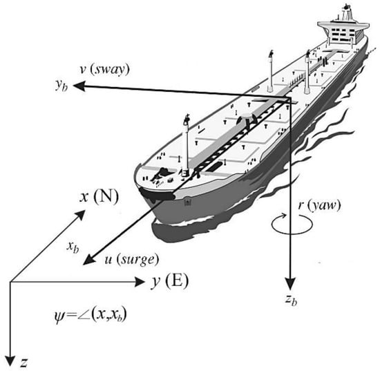
Figure 1.
The earth-fixed and body-fixed coordinate systems, and .
2.2. Controller Design
The control design proposed in this paper was inspired by the dissertation of Wang [38], in which a trajectory-tracking sliding mode controller is designed for underactuated surface vessels. The tracking error can be defined as:
where and are the position errors, and are the positions of tracking target, and are the speed errors, and and are expected speeds to be determined.
According to Equations (1)–(3), the following is obtained:
The expected speeds and can be defined as:
where and are positive coefficients.
Then (4) can be expressed as:
In order to determine the surge control force , a first-order exponential sliding surface is set as follows:
where is positive coefficient.
The derivative of (7) can be expressed as:
where .
The reaching law of sliding mode can be taken as:
where is a transition function defined as:
where , and are positive coefficients.
Following from Equations (8) and (9), the surge control force is given as:
In order to calculate the yaw control moment , the second-order exponential sliding surface is set as follows:
The derivative of (12) can be expressed as:
where .
Following from Equations (1), (12) and (13), the following obtained:
The reaching law of sliding mode can be taken as:
where is as follows:
where , and are positive coefficients.
The yaw control moment is given as:
2.3. Propeller Model
The propeller thrust and propeller torque can be written as [39]:
where is thrust deduction coefficient in straight running condition, is the density of water, is rotating speed of propeller, is propeller diameter, is added moment of rotary inertia of propeller. The thrust coefficient and torque coefficient can be computed with open-water curves as functions of advanced coefficient , which is expressed as:
where is effective propeller wake fraction.
2.4. Rudder Model
The rudder forces and moments, including the hydrodynamic forces and moments induced on ship’s hull by rudder action, namely , and , can be written as follows [40]:
where is rudder angle, is ratio of hydrodynamic force, is x-coordinate of point on which rudder force acts, and is rudder normal force, which can be written as follows:
where is aspect ratio of rudder, is rudder area, and and are the effective rudder inflow speed and angle, respectively.
2.5. Calculation of Maneuvering Commands and Energy
Under general navigation conditions, rudder is the only device providing the control moment, as shown by the following equation:
Accordingly, the rudder angle is determined. Afterwards, the rudder force in x-coordinate of ship can be simulated. Similarly, the thrust of propeller and the rudder force in x-coordinate provide the control force:
Equation (23) gives the rotating speed of propeller. Then the torque of propeller is simulated by Equation (18). The total energy consumption of propeller for the entire voyage can be simulated as the time integration of power:
2.6. PSO Algorithm
In navigation, a route consists of multiple legs: . In the limitation of sailing time, different speed combinations result in differing energy consumption. In this paper, PSO algorithm is applied to determinate speed combination which corresponds to the minimum energy consumption.
The core formula of PSO algorithm is expressed as follows:
where is the number of particles, is the number of iterations, is the update velocity of speed combination , is the inertia coefficient of update velocity, and are learning factors, is random number between 0 and 1, is the best speed combination in the iteration and is the best speed combination in first j iterations.
2.7. Solution Process
In order to define the optimization problem, the procedure for determining the best ship speed combination is described in form of pseudocode as follows:
- Read ship parameters:
- Hull: length between perpendiculars, breadth of waterline, draught, yaw moment inertia, square coefficient, prismatic coefficient;
- Propeller: diameter, pitch, rotary inertia;
- Rudder: aspect ratio, area, height.
- Read route parameters: waypoints, total sailing time.
- Read upper and lower limits of speed: , .
- Read optimization parameters: , , , and , where is the maximum number of steps of optimization iteration.
- Perform for .
- Set speed combination .
- Update speed: if , ; if , .
- Update ship maneuvering target status: , .
- Calculate the output energy of propeller meeting the requirements of control target status using Equations (1)–(24).
- Update the minimum energy consumption and the corresponding best speed combination , .
- Output the final speed combination .
3. Result and Analysis
In this paper, a large merchant ship is the subject of our model. The main parameters of the hull, propeller and rudder are listed in Table 1 and the parameters of the optimization model are listed in Table 2. The model runs on a high-performance server with 80 i5 processors. The total calculated time is about 13 min. Considering that shipowners expect the response time to be half an hour, the calculation efficiency of this current model satisfies the application requirement. Figure 2 shows a section of the ship’s route which is divided into five legs with six waypoints. The coordinates of the six waypoints are as follows:

Table 1.
Main parameters of the hull, propeller and rudder.

Table 2.
Parameters of the optimization model.
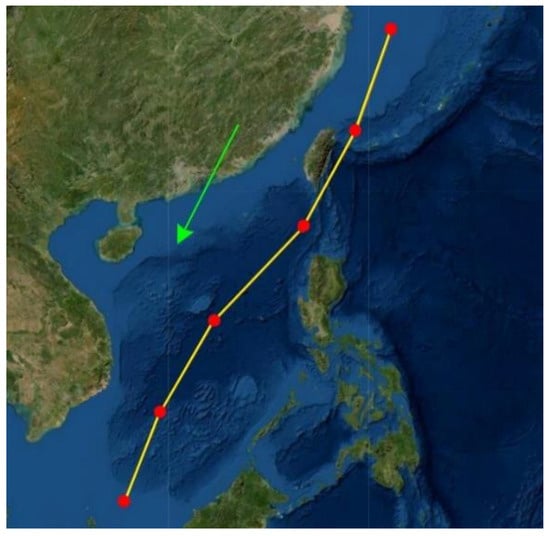
Figure 2.
A section of route with five legs and six waypoints.
Each leg is a rhumb line and the ship sails at a constant speed along it. The rhumb line’s thematic calculation [41] is applied for the conversion between the geographical coordinates and plane coordinates.
The accuracy and robustness of the maneuvering control model are the basis of the speed optimization. In this paper, two navigation scenarios are applied for validation. The speed combination is set as:
Figure 3 shows the results of sailing in the still water scenario. It is found that the calculated track and heading coincide with target ones well. The route length is more than 1740 n miles, while the maximum distance error is less than 0.02 n mile. Moreover, the speed error is less than 0.006 kn. A large increase in the error occurs at the moment the ship turns. The main reason is that the planned route is a combination of multiple broken lines, while the actual route is a continuous smooth curve. Figure 4 shows the results of sailing with the effects of the wind, waves and currents. The effect of currents is added as a velocity vector in the earth-fix coordinate system. The velocity vector is as follows:
where stands for the number of hours.
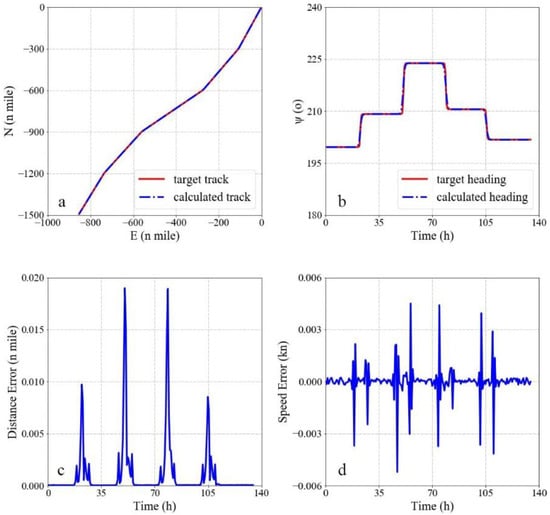
Figure 3.
Results of sailing in the still water scenario. (a) Comparison of the track, (b) comparison of heading, (c) distance error, and (d) speed error.
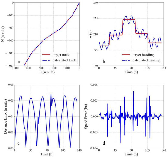
Figure 4.
Results of sailing under the effects of the wind, waves and currents. (a) Comparison of the track, (b) comparison of heading, (c) distance error, and (d) speed error.
The wind speed is 8.0~10.7 m/s and the wave height is 2.5~4 m under level 5 sea conditions. According to IMO ISO15016:2015 [42], the amplitude of the wind load and wave load on the large merchant ship is N. To indicate the influence of a level 5 sea state, which is quite rough for navigation, the total load of the wind and waves are set as:
where stands for the number of days.
The calculated heading changes periodically near the target heading. This is because the ship does not have a separate lateral controller during navigation and can only balance the transverse load of the current by turning the ship’s heading, which is controlled by the rudder. Due to the heading change, the calculated track matches the target track well. The maximum distance error is less than 0.07 n mile and the speed error is less than 0.006 kn. It shows that the maneuvering control model can still ensure high accuracy under a level 5 sea state. In repeated tests, the model outputs the optimization results within the expected time, which proves the model is robust.
To verify the control algorithm, the PSO algorithm is applied to determine the best speed combination under each navigation scenario. The time limitation is that the sailing time is 6 days, which corresponds to the weather forecast time. The speed limitation is as follows:
Figure 5 shows the optimization result of the still water scenario. The best speed combination is , which means that the ship sailing at a constant speed is the most energy-saving in still water. According to the survey, captains tend to keep a constant speed under calm sea conditions. The simulated result is consistent with the actual experience of captains. Correspondingly, the rotating speed of the propeller remains at 45.1 rpm. The rudder is steered only when the ship is turning. Figure 6 shows the optimization result under the effects of the wind, waves and currents. The best speed combination is . It shows that ships should sail slower to save energy under rough sea conditions, because the energy consumption changes sharply with the ship speed. In contrast, ships should sail faster under calm sea conditions to meet the requirements for the total sailing time. Under these conditions, the energy consumption will not increase too much. With this speed strategy, the energy consumption of voyages can be lowered. This result is also consistent with the actual experiences of many captains. The energy consumption of the best speed combination is 1% lower than that of sailing at a constant speed. It is a considerable optimization effect for a large shipping company, which means that millions of USD can be saved. The rotating speed of the propeller and the rudder angle both show obvious responses to the changes in the wind, waves and currents.
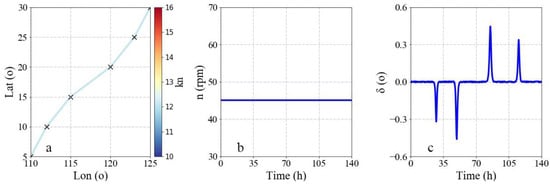
Figure 5.
Optimization result of still water scenario. (a) Speed distribution, (b) rotating speed of propeller command, and (c) rudder angle command.
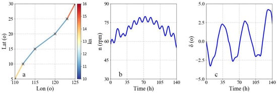
Figure 6.
Optimization result under the effects of the wind, waves and currents. (a) Speed distribution, (b) rotating speed of propeller command, and (c) rudder angle command.
At present, due to the crew’s operating habits, the rotating speed of the propeller does not change frequently. Moreover, the steering engine is not operated in sync with the propeller. These defects lead to additional energy consumption. Regarding unmanned ships, the rotating speed of the propeller command and the rudder angle command can be executed synchronously by a machine. In this way, this optimization model can be helpful.
4. Conclusions
In order to meet the demand for energy-saving technology for autonomous navigation ships in the future, an optimization model of ship speed based on maneuvering control is established in this paper. The trajectory-tracking theory and sliding mode control method are applied to simulate the control load of a ship. The propeller mode and rudder mode are used to calculate the corresponding rotating speed of the propeller, rudder angle and energy consumption. The accuracy and robustness of the maneuvering control model are validated in the still water scenario and the level 5 sea state scenario. On this basis, the PSO algorithm is applied to determine the best speed combination. The result shows that sailing at a constant speed is the most energy-saving strategy in still water. Meanwhile, under the effects of the wind, waves and currents, ships should sail faster when the sea state is calm and slower when the sea state is rough.
Our work concerned optimization, and did not measure the total fuel consumption; thus, it was not a direct measure of the operation of actual ships. This is the focus of our research in the next stage. Moreover, we will introduce non-parametric static tools [43] to study the optimization effects of different algorithms, analyze the parameter sensitivity [44] of the model and so on.
Author Contributions
This article was a team effort. Conceptualization, X.L.; Methodology, X.F. and X.H.; Investigation, X.F. and X.H.; Data curation, K.Z.; Writing—original draft, X.F.; Writing—review & editing, X.H.; Supervision, Y.G.; Project administration, Y.G.; Funding acquisition, X.L. All authors have read and agreed to the published version of the manuscript.
Funding
This work is financially supported by the Research on Key Technology of Development of Intelligent Technology Test Ship (under Grants CJ01N20).
Institutional Review Board Statement
Not applicable.
Informed Consent Statement
Not applicable.
Data Availability Statement
Not applicable.
Acknowledgments
The authors wish to thank Yao Qin of Shanghai Merchant Ship Design and Research Institute, Jia-rong Liu and Yong-sheng Zhao of Shanghai Jiao Tong University for their suggestions for this paper. We would also like to thank the anonymous reviewers whose valuable and helpful comments greatly improved the manuscript.
Conflicts of Interest
The authors declare that they have no known competing financial interest or personal relationship that could have influenced the work reported in this paper. The funders had no role in the design of the study; in the collection, analyses, or interpretation of data; in the writing of the manuscript; or in the decision to publish the results.
References
- Xu, L.; Chen, L. Analysis on energy conservation efficiency for ocean-going sail-assisted bulk carrier. In Proceedings of the IEEE 2010 International Conference on Mechanic Automation and Control Engineering, Wuhan, China, 26–28 June 2010. [Google Scholar]
- International Maritime Organization (IMO). Fourth IMO GHG Study 2020-Final Report; CE Delft: Delft, The Netherlands, 2020.
- Fan, X.; Sun, H.; Xiang, X. Investigation on Trim Optimization of a Bulk Carrier Based on CFD Method. The Proceedings of 30th International Ocean and Polar Engineering Conference, Online, 11–16 October 2020; International Society of Offshore and Polar Engineers: Shanghai, China, 2020. [Google Scholar]
- Vettor, R.; Soares, C.G. Development of a ship weather routing system. Ocean Eng. 2016, 123, 1–14. [Google Scholar] [CrossRef]
- Vettor, R.; Tadros, M.; Ventura, M.; Guedes Soares, C. Route planning of a fishing vessel in coastal waters with fuel consumption restraint. Marit. Technol. Eng. 2016, 3, 167–173. [Google Scholar]
- Elkafas, A.G.; Shouman, M.R. Assessment of energy efficiency and ship emissions from speed reduction measures on a medium sized container ship. Int. J. Marit. Eng. 2021, 163. [Google Scholar] [CrossRef]
- Taskar, B.; Andersen, P. Benefit of speed reduction for ships in different weather conditions. Transp. Res. Part D Transp. Environ. 2020, 85, 102337. [Google Scholar] [CrossRef]
- Tadros, M.; Vettor, R.; Ventura, M.; Guedes Soares, C. Effect of propeller cup on the reduction of fuel consumption in realistic weather conditions. J. Mar. Sci. Eng. 2022, 10, 1039. [Google Scholar] [CrossRef]
- Ryder, S.C.; Chappell, D. Optimal Speed and Ship Size for the Liner Trades; Maritime Transport Centre, University of Liverpool: Liverpool, UK, 1979. [Google Scholar]
- Ronen, D. The effect of oil price on the optimal speed of ships. J. Oper. Res. Soc. 1982, 33, 1035–1040. [Google Scholar] [CrossRef]
- Corbett, J.J.; Wang, H.; Winebrake, J.J. The effectiveness and costs of speed reductions on emissions from international shipping. Transp. Res. Part D 2009, 14, 593–598. [Google Scholar] [CrossRef]
- Meng, Q.; Wang, T. A chance constrained programming model for short-term liner ship fleet planning problems. Marit. Policy Manag. 2010, 37, 329–346. [Google Scholar] [CrossRef]
- Perakis, A.N.; Papadakis, N.A. Fleet deployment models, Part 1. Marit. Policy Manag. 1987, 14, 127–144. [Google Scholar] [CrossRef]
- Perakis, A.N.; Papadakis, N.A. Fleet deployment optimization models. Part 2. Marit. Policy Manag. 1987, 14, 145–155. [Google Scholar] [CrossRef]
- Wang, S.; Meng, Q. Sailing speed optimization for container ships in a liner shipping network. Transp. Res. Part E 2012, 48, 701–714. [Google Scholar] [CrossRef]
- Wen, M.; Pacino, D.; Kontovas, C.A.; Psaraftis, H.N. A multiple ship routing and speed optimization problem under time, cost and environmental objectives. Transp. Res. Part D Transp. Environ. 2017, 52, 303–321. [Google Scholar] [CrossRef]
- Zaafouri, A.; Regaya, C.B.; Azza, H.B.; Châari, A. DSP-based adaptive backstepping using the tracking errors for high-performance sensorless speed control of induction motor drive. ISA Trans. 2016, 60, 333–347. [Google Scholar] [CrossRef] [PubMed]
- Regaya, C.B.; Farhani, F.; Zaafouri, A.; Chaari, A. A novel adaptive control method for induction motor based on Backstepping approach using dSpace DS 1104 control board. Mech. Syst. Signal Process. 2018, 100, 466–481. [Google Scholar] [CrossRef]
- Pettersen, K.Y.; Nijmeijer, H. Underactuated ship tracking control: Theory and experiments. Int. J. Control 2001, 74, 1435–1446. [Google Scholar] [CrossRef]
- Do, K.D.; Jiang, Z.P.; Pan, J. Underactuated ship global tracking under relaxed conditions. IEEE Trans. Autom. Control 2002, 47, 1529–1536. [Google Scholar] [CrossRef]
- Yan, Z.; Wang, J. Model predictive control for tracking of underactuated vessels based on recurrent neural networks. IEEE J. Ocean. Eng. 2012, 37, 717–726. [Google Scholar] [CrossRef]
- Dong, Z.; Wan, L.; Li, Y.; Liu, T.; Zhang, G. Trajectory tracking control of underactuated USV based on modified backstepping approach. Int. J. Nav. Archit. Ocean Eng. 2015, 7, 817–832. [Google Scholar] [CrossRef]
- Xu, J.; Wang, M.; Qiao, L. Dynamical sliding mode control for the trajectory tracking of underactuated unmanned underwater vehicles. Ocean Eng. 2015, 105, 54–63. [Google Scholar] [CrossRef]
- Elmokadem, T.; Zribi, M.; Youcef-Toumi, K. Trajectory tracking sliding mode control of underactuated AUVs. Nonlinear Dyn. 2016, 84, 1079–1091. [Google Scholar] [CrossRef]
- Wang, B.; Liu, L.; Li, Y.; Khishe, M. Robust Grey Wolf Optimizer for Multimodal Optimizations: A Cross-Dimensional Coordination Approach. J. Sci. Comput. 2022, 92, 1–30. [Google Scholar] [CrossRef]
- Wei, K.; Khishe, M.; Mohammadi, M. Dynamic levy flight chimp optimization. Knowl.-Based Syst. 2022, 235, 107625. [Google Scholar]
- Bo, Q.; Cheng, W.; Khishe, M. Evolving chimp optimization algorithm by weighted opposition-based technique and greedy search for multimodal engineering problems. Appl. Soft Comput. 2022, 132, 109869. [Google Scholar] [CrossRef]
- Wang, C.N.; Yang, F.C.; Nguyen, V.T.T.; Vo, N.T. CFD analysis and optimum design for a centrifugal pump using an effectively artificial intelligent algorithm. Micromachines 2022, 13, 1208. [Google Scholar] [CrossRef]
- Nguyen, T.V.; Huynh, N.T.; Vu, N.C.; Kieu, V.N.; Huang, S.C. Optimizing compliant gripper mechanism design by employing an effective bi-algorithm: Fuzzy logic and ANFIS. Microsyst. Technol. 2021, 27, 3389–3412. [Google Scholar] [CrossRef]
- Kennedy, J.; Eberhart, R. Particle swarm optimization. In Proceedings of the IEEE ICNN’95-International Conference on Neural Networks, Perth, Australia, 27 November–1 December 1995. [Google Scholar]
- Hassan, R.; Cohanim, B.; De Weck, O.; Venter, G. A comparison of particle swarm optimization and the genetic algorithm. In Proceedings of the 46th AIAA/ASME/ASCE/AHS/ASC structures, structural dynamics and materials conference, Austin, TX, USA, 18–21 April 2005. [Google Scholar]
- Zhao, W.; Wang, Y.; Zhang, Z.; Wang, H. Multicriteria ship route planning method based on improved particle swarm optimization–genetic algorithm. J. Mar. Sci. Eng. 2021, 9, 357. [Google Scholar] [CrossRef]
- Carlisle, A.; Dozier, G. An off-the-shelf PSO. In Proceedings of the Workshop on Particle Swarm Optimization; Purdue School of Engineering and Technology: Indianapolis, IN, USA, 2001. [Google Scholar]
- Ganesh, M.R.; Krishna, R.; Manikantan, K.; Ramachandran, S. Entropy based binary particle swarm optimization and classification for ear detection. Eng. Appl. Artif. Intell. 2014, 27, 115–128. [Google Scholar] [CrossRef]
- Faieghi, M.R.; Naderi, M.; Jalali, A.A. Design of fractional-order PID for ship roll motion control using chaos embedded PSO algorithm. In Proceedings of the IEEE 2011 2nd International Conference on Control, Instrumentation and Automation, Bandung, Indonesia, 27–29 December 2011. [Google Scholar]
- Kang, Y.T.; Chen, W.J.; Zhu, D.Q.; Wang, J.H.; Xie, Q.M. Collision avoidance path planning for ships by particle swarm optimization. J. Mar. Sci. Technol. 2018, 26, 777–786. [Google Scholar]
- Hamdi, H.; Regaya, C.B.; Zaafouri, A. Real-time study of a photovoltaic system with boost converter using the PSO-RBF neural network algorithms in a MyRio controller. Sol. Energy 2019, 183, 1–16. [Google Scholar] [CrossRef]
- Wang, Y. Research of Nonlinear Sliding Mode Control for Underactuated Surface Vessel Trajectory Tracking; Dalian Maritime University: Dalian, China, 2015. [Google Scholar]
- Hirano, M. A Practical Calculation Method of Ship Maneuvering Motion at Initial Design Stage. Nav. Archit. Ocean Eng. 1981, 19, 68–80. [Google Scholar]
- Ogawa, A.; Kasai, H. On the mathematical model of maneuvering motion of ships. Int. Shipbuild. Prog. 1978, 25, 306–319. [Google Scholar] [CrossRef]
- Fan, X.; Gao, W.; Sun, H. Application of the rhumb-line computation in the route management of smart ships. J. Ship Des. 2019, 2, 33–37. [Google Scholar]
- ISO 15016:2015; Ships and Marine Technology—Guidelines for the Assessment of Speed and Power Performance by Analysis of Speed Trial Data. ISO: Geneva, Switzerland, 2015.
- Qiao, W.; Khishe, M.; Ravakhah, S. Underwater targets classification using local wavelet acoustic pattern and Multi-Layer Perceptron neural network optimized by modified Whale Optimization Algorithm. Ocean Eng. 2021, 219, 108415. [Google Scholar] [CrossRef]
- Hu, T.; Khishe, M.; Mohammadi, M.; Parvizi, G.R.; Karim, S.H.T.; Rashid, T.A. Real-time COVID-19 diagnosis from X-Ray images using deep CNN and extreme learning machines stabilized by chimp optimization algorithm. Biomed. Signal Process. Control 2021, 68, 102764. [Google Scholar] [CrossRef]
Disclaimer/Publisher’s Note: The statements, opinions and data contained in all publications are solely those of the individual author(s) and contributor(s) and not of MDPI and/or the editor(s). MDPI and/or the editor(s) disclaim responsibility for any injury to people or property resulting from any ideas, methods, instructions or products referred to in the content. |
© 2022 by the authors. Licensee MDPI, Basel, Switzerland. This article is an open access article distributed under the terms and conditions of the Creative Commons Attribution (CC BY) license (https://creativecommons.org/licenses/by/4.0/).