Article

Downsizing the Linear PM Generator in Wave Energy Conversion for Improved Economic Feasibility

Department of Maritime & Transport Technology, Delft University of Technology, 2268 CD Delft, The Netherlands
*
Author to whom correspondence should be addressed.
J. Mar. Sci. Eng. 2022, 10(9), 1316; https://doi.org/10.3390/jmse10091316
Submission received: 18 August 2022 / Revised: 9 September 2022 / Accepted: 13 September 2022 / Published: 17 September 2022

Abstract

:
A crucial part of wave energy converters (WECs) is the power take-off (PTO) mechanism, and PTO sizing has been shown to have a considerable impact on the levelized cost of energy (LCOE). However, as a dominating type of PTO system in WECs, previous research pertinent to PTO sizing did not take modeling and optimization of the linear permanent magnet (PM) generator into consideration. To fill this gap, this paper provides an insight into how PTO sizing affects the performance of linear permanent magnet (PM) generators, and further the techno-economic performance of WECs. To thoroughly reveal the power production of the WEC, both hydrodynamic modeling and generator modeling are incorporated. In addition, three different methods for sizing the linear generator are applied and compared. The effect of the selection of the sizing method on the techno-economic performance of the WEC is identified. Furthermore, to realistically reflect the relevance of PTO sizing, wave resources from three European sea sites are considered in the techno-economic analysis. The dependence of PTO sizing on wave resources is demonstrated.

1. Introduction

Ocean waves contain substantial energy, which can be exploited as an important supplementary of clean energy next to wind and solar energy. Wave energy has been investigated over decades as a renewable energy resource [1,2,3]. Over 200 different types of wave energy converters (WECs) have been reported, but they are still far away from large-scale commercialization [4,5,6]. This mainly results from the fact that WECs correspond to a higher value of the levelized cost of energy (LCOE) than other technologies of renewable energy [4,7]. Therefore, it is significant to bring the LCOE down for the further development of WECs.
In the operation of WECs, wave energy is first absorbed as a form of mechanical energy by the interaction between the buoy and incoming waves [8]. The absorbed mechanical energy is then converted into usable electricity by a power take-off (PTO) system. As a core component, the PTO capacity is highly influential to the techno-economic performance of WECs. According to recent scientific research, reducing the PTO capacity to an appropriate level helps to lower the LCOE of WECs [9,10,11]. On the one hand, the PTO capacity is directly related to the cost. As stated in [12], PTO systems normally account for over 20% of total capital expenditure (CAPEX), and oversized PTO systems are therefore not economically favorable. On the other hand, the PTO capacity indicates the physical constraints, such as force, peak power and displacement limit. In order to comply with them, the PTO parameters are usually required to be adapted, which consequently confines the mechanical energy absorption of WECs. A collective sizing method considering both buoy and PTO sizing has been proposed to improve the techno-economic performance of WECs [9]. It has been applied to a point absorber WEC in three different wave sites, leading to the conclusion that suitably sizing WECs could reduce the LCOE. More specifically, downsizing the PTO capacity is rather effective. For instance, it has the potential to decrease the LCOE by over 30% in particular circumstances. However, some assumptions in the reference [9] need to be further studied when evaluating the power performance of WECs with differently sized PTO capacities. The influence of PTO sizing could play a role at two conversion stages in the power extraction. Firstly, the PTO capacity is highly related to the physical limits, which determines the maximum absorbed power. Secondly, the PTO sizing inevitably brings changes to its design, which might make a difference to the conversion efficiency from the absorbed power to the electrical power. The second aspect was not taken into account in previous papers [9,10,11] discussing the PTO downsizing, in which the PTO size on the power conversion efficiency was neglected. Hence, a better understanding of the effect of the sizing on PTO conversion efficiencies is expected to improve the size optimization methods of WECs.
Among various types of PTO systems in WECs, linear generators have received significant attention because of their high efficiencies and low maintenance demands [2,13]. However, the effect of sizing on the performance of linear generators of WECs is rarely discussed in literature even though downsizing the PTO capacity has shown the potential to reduce the LCOE. A preliminary work of this study has been reported in [1], in which the sizing of the generator was roughly performed without optimizing the main geometric parameters. In addition, the variation of the wave resource was not taken into account even though it is of significance to the size determination of WECs [14]. To address these issues, the present paper is thus extended to further demonstrate how the sizing affects the techno-economic performance of WECs equipped with linear permanent magnet (PM) generators as the PTO system.
This paper begins with a literature review of the application of the linear generator in wave energy conversion. Then, the WEC concept is described, and the specification of the linear PM generator reference is given. Next, the method to calculate the power performance of the WEC is presented, in which both hydrodynamic modeling and electrical modeling are considered. The main design parameters of the generator are resized to minimize the LCOE for a realistic sea site. For comparison, three different sizing methods of the electrical machines are applied to determine the optimal PTO capacity. The influence of sizing methods on the resized generator performance, the AEP and the LCOE of the WEC are analyzed. Moreover, the dependence of the generator efficiency and PTO size determination on the characteristics of wave resources is discussed. Finally, conclusions are drawn.

2. Review of the Application of Linear Generator in Wave Energy Conversion

The commonly used PTO systems in WECs are divided into five types by their operating principles, and they are briefly introduced below.
  • Hydraulic PTO: In hydraulic PTO, the motion of a buoy drives the hydraulic piston to increase the pressure of the working medium. Then, the pressure of the medium is raised sufficiently high in an accumulator to rotate the hydraulic motor. The hydraulic PTO is robust and able to provide large forces at low frequencies, which highly matches the dynamic characteristics of WECs. Hydraulic PTO systems were widely used in WECs, such as Pelamis and Edinburgh Duck [15,16,17]. However, hydraulic PTO systems contain plenty of moving parts, which results in their complex structure. So, regular system maintenance and inspection are normally required, which is time-consuming and costly [2]. In addition, the conversion efficiencies of hydraulic PTO systems are relatively low [18].
  • Hydro PTO: The hydro PTO mainly refers to the hydro turbine. Hydro turbines transfer the fluid flow to electricity. This type of PTO systems is commonly employed in overtopping devices, such as WaveDragon [19].
  • Pneumatic PTO: The pneumatic turbine generally refers to the air turbine, which is driven by the oscillating air pressure. This technology is usually utilized in oscillating water column converters [20].
  • Mechanical PTO: In the mechanical PTO system, a gearbox is used to convert the linear movement of the buoy of WECs to rotary motion for fitting conventional rotary generators. The oscillation of the buoy of WECs is of low speed due to the characteristics of ocean waves. For improving efficiency, another important function of the gearbox is to increase the speed of motion. In [21], a point absorber equipped with a bidirectional gearbox and rotary generator was introduced. More recently, WECs with mechanical PTO mechanism have been further investigated by numerical modeling [22] and small-scale testing [23].
  • Direct-drive linear generator: The linear generator could be used as the direct-drive PTO system in the oscillating body WECs, and they are usually used in point absorber wave energy converters, such as AWS [24]. In direct-drive linear generators, intermediate transmission interfaces, such as gearbox and hydraulic motors, are not necessary. Instead, the oscillating buoy is directly coupled with the translator of the linear generator. The linear generators are commonly associated with higher efficiencies compared with other PTO systems. This is because there are less transmission losses resulting from a reduced number of energy conversion steps [2,24]. In addition, the reduced number of components in the PTO system increases the reliability of the whole WEC system [25].
The linear generator has been thought of as an appealing solution for wave energy technologies among all types of PTO systems because of the mentioned advantages. Hence, this paper concentrates on the WECs with a linear generator. Linear generators have been investigated and developed for application in WECs over years. For various WEC prototypes that have been successfully tested in the real oceanic environment, linear generators were serving as the PTO system [26,27]. So far, three full-scale WEC technologies equipped with the linear generator, excluding their updated versions, have been successfully tested in real oceanic climates. The key information of their prototypes is presented in Table 1.
The Archimedes Wave Swing (AWS) was the first large-scale WEC project using the linear generator [24]. It is a fully submerged WEC device, and it produces energy relying on the pressure difference on the moving part of the device when the ocean wave passes above. The linear generator in the AWS was designed to be double-sided for avoiding the huge force of attraction between the translator and stator. The maximum peak power of the tested prototype was 2 MW, which is remarkably high in the field of wave energy conversion [27]. Uppsala university developed a floating point absorber WEC concept, and the first full-scale prototype was deployed at the Lysekil research site in Sweden in 2006. Since then, thirteen follow-up prototypes have been deployed [28]. This WEC consists of a floating buoy and a linear generator founded on the seabed. The buoy is connected to the translator of the generator through a connection line. In the generator, the translator moves vertically along the rail, and four stator packages are mounted on a pillar fixed at the foundation structure [26]. Oregon University developed a dual-body WEC in which a linear generator was incorporated, called SeaBeavI Project [29]. The ocean testing of its 10 kW prototype was performed in Yaquina Bay in 2007. This WEC includes a moored cylindrical spar and a floating buoy. The heave motion of the spar is restrained by the mooring system, but the buoy is free to move vertically relative to the spar. In this concept, the spar and buoy act as the translator and stator of the linear generator, respectively. The coils are wound on the interior surface of the spar and permanent magnets are placed on the buoy. Besides, this generator was configured as a tubular geometry [25]. These three linear generators share some common features. First, all of them are permanent-magnet (PM) synchronous machines. Second, they are all longitudinal flux machines. Since the successful tests of these three concepts, a series of extensive studies have been performed. They were mainly intended to address the negative characteristics of linear generators when serving WECs.
The application of linear generators in wave energy conversion also faces some challenges. Firstly, the dimensions of linear generators are much larger than standard electrical machines for sustaining a similar power level. This results from the low typical speed of WECs. One solution to reduce the dimension is the use of transverse flux linear machines. The advantage of the transverse flux machines is the high force density, which results from the flux concentration and decoupled magnetic and electrical circuits [30]. In [31,32,33], WECs with transverse flux linear generators were investigated, in which a lower cost of permanent magnets and higher force/power density were indicated. However, their fabrication is much more complex than the longitudinal flux machines, and their leakage paths also lead to low power factors [30]. As a consequence, they have not been as of much interest as the longitudinal flux machines in the field of WECs. Another possible solution is to increase the movement speed of WECs. For example, a speed amplified linear generator was proposed for a WEC concept in [34], and the relative speed between the stator and translator was therefore increased. The second challenge is that the conversion efficiency of linear generators in WECs is still limited compared to other applications of direct-drive systems. This is because the induced voltage is decreased by the low speed and then a large current is required to produce the generator force. In this case, the resistive losses on the conductors are high. In [35,36,37], superconducting linear generators were studied to improve it. The results showed that superconducting generators could clearly contribute to the high efficiency and force density. This is because they are associated with less resistivity and a stronger magnetic field compared to conventional machines. However, the difficulty and high expense of making the cryogenic temperature in an oceanic environment are still hurdles in practice.

3. Description of WEC Concept

In this section, the WEC concept and the design of the reference linear PM generator are described. Figure 1 illustrates the concept of the investigated heaving point absorber, and the PTO mechanism of the concept is considered to be a linear PM generator. Figure 1 also depicts the connection scheme of the PM generator with the electrical converter and the grid. A three-phase back-to-back voltage source converter is applied here to regulate the stator current and terminal voltage because of its high efficiency [27]. The converter is connected to the output side of the linear generator. In the concept studied in the present paper, the translator of the bottom-founded machine is directly connected to the floating buoy. The radius of the spherical floater was designed to be 2.5 m, and the buoy draft is 2.5 m as well in still water. During operation, the incoming wave force excites the floater to oscillate in the heaving direction. The stroke of the point absorber is set as 4 m, and the maximum allowed velocity u s is 1.25 m/s. To avoid excessive motion, the generator has end stop mechanisms mounted on both the top and bottom. More details about modeling, design and the sea trial test of the reference generator can be found in [27,38].
In Figure 2a, a photo of the reference linear PM machine applied in the prototype of the AWS wave energy converter is shown. Figure 2b illustrates the cross-section of the reference linear PM generator, which indicates that it is a three-phase machine. The machine was designed to be double-sided so as to counteract the force of attraction between the translator and stator [39]. Magnets are placed on the translator segments, and coils are wound on the stator segments. Different from rotary electrical machines, the partial overlap between the translator and stator could happen to the linear generator. This phenomenon makes a part of the material of the machine unproductive during operation, which is negative to the conversion efficiency. It is known that a longer translator is able to reduce the occurrence of the partial overlap, but it could clearly increase the cost. Hence, a compromise always has to be made, and the translator was 3 m longer than the stator in the design of the reference machine.
The key design parameters of the reference linear PM generator are specified in Table 2. As the design parameters of the original reference machine were not fully disclosed, some parameters (including the air gap length, slot width, pole width, tooth width and magnet thickness) were referred to the design of a direct-drive wind turbine generator design [40]. The referred generator has a similar power rating and maximum designed force to the reference machine studied in this paper. It is considered fair since this work is focused on the effect of the generator sizing instead of its design phases.

4. Methodology

In this section, a frequency domain model is established to calculate the hydrodynamic responses of the buoy. Next, an analytical model is presented to calculate the generator performance. Furthermore, the principle and optimization for resizing the generator are explained. Finally, an economic model necessary for analyzing the techno-economic performance is built.

4.1. Hydrodynamic Modeling

Based on linear wave theory, a frequency domain model is derived for the WEC. The buoy is constrained to oscillate in the heaving direction, thus only this degree of freedom is considered in the modeling. According to Newton’s second law, the motion of the WEC as a rigid body can be described as
m d u ( t ) d t = F hs ( t ) + F e ( t ) + F pto ( t ) + F r ( t )
where m is the mass of the oscillating body,
F hs is the hydrostatic force,
F e is the wave excitation force,
F r is the wave radiation force,
F pto is the PTO force, and
u is the velocity of the rigid body. If the body is assumed to perform harmonic motion under regular waves and a linear PTO model is used to simulate the dynamic behaviour of the PTO system, (1) could be rewritten in the form of complex amplitudes [41] as,
F ^ e ( ω ) = [ R i ( ω ) + R p t o ] u ^ + i ω u ^ [ m + M r ( ω ) ] + i u ^ ( K p t o ω S w l ω )
where R i ( ω ) is the hydrodynamic damping coefficient, R p t o is the PTO damping coefficient, ω is the wave frequency, M r ( ω ) is the added mass of the buoy, u ^ is complex amplitude of the vertical velocity, K p t o is the PTO stiffness coefficient and S w l is the hydrostatic stiffness.
The intrinsic impedance of the heaving buoy and PTO impedance can be introduced as,
Z i ( ω ) = R i ( ω ) + i X i ( ω )
X i ( ω ) = ω [ m + M r ( ω ) ] S w l ω
where Z i ( ω ) and X i ( ω ) embody the intrinsic impedance and the intrinsic reactance of the buoy respectively. Similarly, the impedance of PTO Z p t o ( ω ) and reactance of p t o ( ω ) can be given as,
Z p t o ( ω ) = R p t o ( ω ) + i X p t o ( ω )
X p t o ( ω ) = K p t o ω
In this work, only the passive control strategy is used, which implies that there is only PTO damping force exerted on the WEC. Thus, (2) can be rewritten as,
F ^ e ( ω ) = [ Z i ( ω ) + R p t o ( ω ) ] u ^
The hydrodynamic characteristics of floating bodies, including M r ( ω ) , R i ( ω ) and F e ( ω ) , are calculated numerically using the Boundary Element Method through the open source software Nemoh [42]. Then, by solving (7), the complex amplitude of velocity u ^ could be obtained as,
u ^ = F ^ e Z i + R p t o
In regular wave conditions, the time-averaged absorbed mechanical power can be obtained and expressed as,
P ¯ = 1 2 R p t o u ^ 2
The complex amplitude of the required generator force (or PTO force) is derived as,
F ^ g e = R p t o u ^
The amplitude of the the required generator force can be derived by substituting (8) to (10), and it gives
F ^ g e ( ω ) = R p t o F ^ e ( ω ) Z i + R p t o = R p t o Z i + R p t o F ^ e ( ω )

4.2. Generator Modeling

The performance of variously sized generators is calculated based on an analytical generator model. Validation of the model has been performed through a full-scale test [38]. As magnetic saturation only plays a very limited role in this linear generator design [43], and the effect is neglected in this study.
In the air gap, the magnets on the translator induce the magnetic flux density, and its fundamental space harmonic is calculated as,
B ^ g m = l m μ r m g e f f B r m 4 π sin ( π b p 2 τ p )
where l m , μ r m and g e f f embody the magnet length in the magnetization direction, the recoil permeability of the magnets and the effective air gap, respectively. B r m represents the remnant flux density of the permanent magnets. According to [38], when the translator is moving, the induced no-load phase voltage in the stator winding can be calculated as
E p = 2 p l s N s k w u B ^ g m l a c t L s
where u is the floater velocity, p is the number of pole pairs, l a c t is the actual length of the overlap between the stator and translator, and k w is the winding factor. l a c t is a function of translator displacement, and it can be calculated as
l a c t ( z ) = L s , f o r | z | < 0.5 ( L t L s ) 0 , f o r | z | > 0.5 ( L t + L s ) 0.5 ( L t + L s ) | z | , e l s e
where z represents the displacement of the translator (or the floater). The stator phase resistance R t is calculated from the machine dimensions, the number of turns in a slot and the cross-section of a slot:
R t = ρ C u l C u s A C u s = ρ C u 2 N s 2 ( l s + 2 τ p ) p h s b s k s f i l
where ρ C u is the resistivity of copper, and k s f i l is the copper fill factor of the slots. The iron losses are calculated as
P F e s = P F e 0 ( m F e s t ( B ^ s t B 0 ) 2 + m F e s y ( B ^ s y B 0 ) 2 ) f e f 0
where P F e 0 is the iron loss per unit mass at a frequency f 0 and flux density B 0 , m F e s t and m F e s y are the mass of the stator teeth and the stator yoke, respectively, and f e is the electrical generator frequency. B ^ s t and B ^ s y embody the fundamental space harmonic of the magnetic flux density in the stator and yoke, respectively. This is a rough approximation of the iron losses, in which the iron losses are assumed to be only proportional to the frequency.
After the PTO damping coefficient is derived, the required generator force is calculated based on (10). Then, the power taken by the stator winding of the machine can be expressed as
P w d = F g e v P F e s
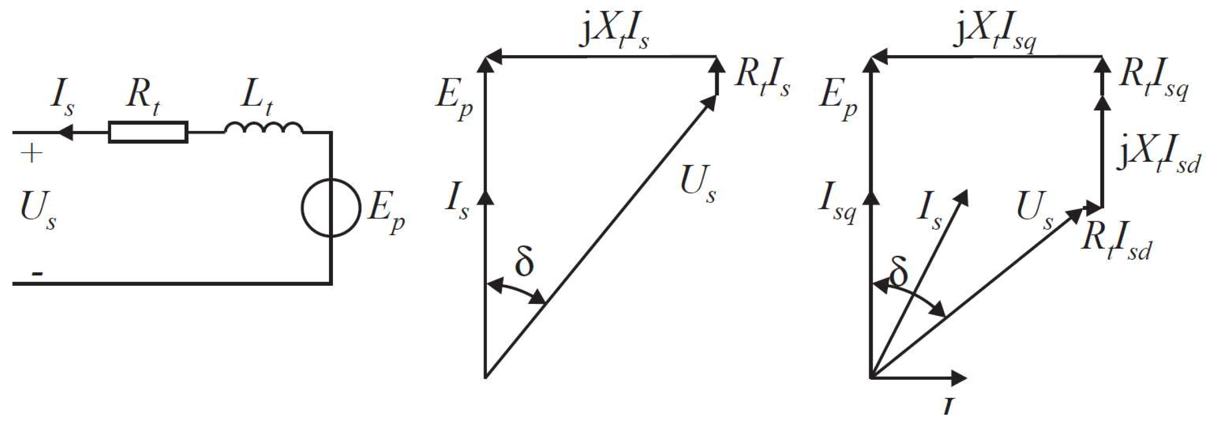
For the sake of higher system efficiency, the operating points of the generator are determined by the method demonstrated in [27]. The stator current I s can be represented by two orthogonal components, namely quadrature (or force making) component I s q and direct (or flux making) component I s d . When the stator current I s is below the maximum current of the converter I c o n m , the direct component I s d is regulated to be zero. In this case, the stator current I s is in phase with the induced no-load voltage E p , as shown in the first phasor diagram in Figure 3. Thus, the current is calculated as
I s = I s q = P w d m E p
When I s is greater than the maximum current of the converter I c o n m , I s is then limited to the defined maximum current. As a result, the actual force provided by the machine is decreased to lower than the required generator force. In this sense, the terminal voltage U s can be calculated as
U s = ( E p I s q R t ) 2 + ( ω e L t I s q ) 2
If U s is about to violate the rated converter voltage U c o n m , it would be limited by a direct component I s d separated from the current, as illustrated in the second phasor diagram in Figure 3. In this condition, if the resulting current is still larger than the maximum converter current, the stator current and terminal voltage are limited to the maximum converter current and voltage. In these situations, the actual generator force would also be penalized.
The converter losses are dependent on three factors. The first one is the constant power dissipation, resulting from control, cooling and power supplies. The second is proportional to the current, representing the switching losses and conduction losses. The third is proportional to the current squared, which is related to conduction losses. Besides, only the losses from the generator side are considered in this model. Therefore, the converter losses can be calculated as
P c o n v = P c o n v m 31 [ ( 1 + 20 I s I s m + 10 ( I s I s m ) 2 ]
where P c o n v m represents the dissipated power of the converter at the rated condition. It is assumed to account for 3% of the rated power [44]. I s m is the maximum generator side current of the converter. In the reference linear machine, the rated power, maximum line voltage and phase current of the converter were specified as 1 MW, 1500 V and 400 A, respectively [27]. The rated power was selected based on the maximum average power of the device.

4.3. Generator Sizing

As characteristics of wave climate vary with locations, sizing of WECs could result in devices better fitting the local wave resource. In the existing literature, PTO systems are commonly sized by the same scaling ratio as the buoy, in which PTO sizing is only playing a limited role. To allow for independent sizing of the PTO system, three sizing methods, different in complexity, are applied in this paper for comparison.
  • Method 1: Scaling law
    The scaling principle of electrical generators is based on the fact that the force density per unit surface area of the machine remains rather constant when its dimension changes [40]. The force density is mainly related to two factors. The first one is the magnetic flux density in the air gap, and it is limited by the effect of magnetic saturation. The second one is the linear current density of the machine, and it is limited by the maximum allowed heat dissipation. These two factors could hardly be changed with the dimension if the topology design of the machine does not vary. In this paper, the machine is resized to suit various maximum forces. The force density of resized machines remains identical to the reference machine.
    For convenience, a scale factor λ is introduced here as,
    λ = S s S o
    where S o and S s embody the geometrical lengths of the original and the scaled generator. In this method, stator, translator and stack length are sized based on an identical scale factor. However, in principle, they can be sized independently as implemented in method 2 introduced in the following text. Besides, only the stator, translator and stack lengths are considered in scaling, and other geometrical parameters of the machine are kept identical. For a fair comparison of differently sized generators, the stroke and speed limits are maintained to be the same. Then, the other parameters are scaled as follows:
    Force : F m a x s F m a x o = λ 2
    Velocity : u m a x s u m a x o = 1
    Current : I c o n s I c o n o = 1
    where subscripts “s” and “o” indicate the scaled machine and original machine.
    The rating of the converter is accordingly scaled for each machine. The rated apparent power, current and terminal voltage should be selected during the rating. As the linear current density is assumed to remain identical for differently sized machines, the maximum phase current of the scaled converter is selected to be unchanged, namely I c o n of 400 A. At the rated operating condition, the velocity of the buoy is u m a x of 1.25 m/s, and then the resulting no-load voltage can be obtained by (13). Additionally, the no-load voltage at the rated point is assumed to be in phase with the current. As a consequence, the rated terminal voltage of the scaled converter, U c o n s , and the phase angle between the current and terminal voltage, namely δ , can be calculated according to the first phasor diagram in Figure 3. Therefore, the rated apparent power of the scaled converter is obtained as
    S c o n v s = m I c o n m U c o n m s
  • Method 2: Scaling with optimization
    In this method, the main parameters of the machine, including the translator length, stator length and stack length are optimized during sizing for the lowest LCOE. The optimization for each designed maximum generator force is expressed as
    m i n i m i z e f = LCOE ( L s , L t , l s ) s u b j e c t t o 2 ρ f o r c e _ r e f L s l s = F l i m i t : c o n s t r a i n t 1 1.2 L s L t : c o n s t r a i n t 2
    where ρ f o r c e _ r e f is the force density of the reference machine, and F l i m i t is the designed maximum generator force. In (26), constraint 1 is associated with the force density. The force density adopted here is considered as 46 kN / m 2 , which is calculated based on the performance identification of the AWS generator in [27]. A factor of 2 is included on the left side of the constraint 1 because the machine is double-sided. Constraint 2 indicates that the translator length is required to be larger than 1.2 times the stator length, which is used to mitigate the effect of partial overlap between stator and translator. The maximum phase current, voltage and the rated apparent power of the scaled converter are calculated based on the same way as introduced in Method 1. As the objective function is computationally expensive in this case, the surrogate algorithm is adopted. In the algorithm, the objective function is approximated by a surrogate function, and therefore the optimization speed can be significantly improved [45]. The optimization is implemented in the Matlab environment (version 2020). The tolerance of the function and the maximum iteration steps are set to 1 × 10 5 and 3000, respectively, and the iteration process is terminated when any of the criteria is crossed.
  • Method 3: Scaling with assuming a constant generator efficiency
    For simplification, in studies discussing the effects of the sizing of WECs, the sizing of WECs was commonly implemented in the absence of the consideration of the variation of generator efficiencies. Instead, a constant energy conversion efficiency from the absorption stage to the grid was assumed. In this method, the generator size acts simply as a PTO force constraint in the hydrodynamic modeling. This method is discussed in this paper for a comparison with the other two above methods to demonstrate the effects of this simplification on the generator size determination and the LCOE estimation. In this paper, this constant efficiency is considered to be 70%, as usually used in literature [9,46]. Moreover, as the design of the generator is not taken into account in this method, the cost could not be derived explicitly. To evaluate the techno-economic performance of WECs, the PTO related cost in this method is assumed to be the same as that estimated in method 2 for each designed maximum generator force limit.

4.4. Economic Modeling

The linear generator is resized to minimize the LCOE of WECs. To assess the LCOE of the WEC with differently sized generators, an economic model is presented in this part. The AEP of the WEC is calculated as
AEP = A · x = 1 x = n P a b s o r b e d ( x ) · η ( x ) · T ( x )
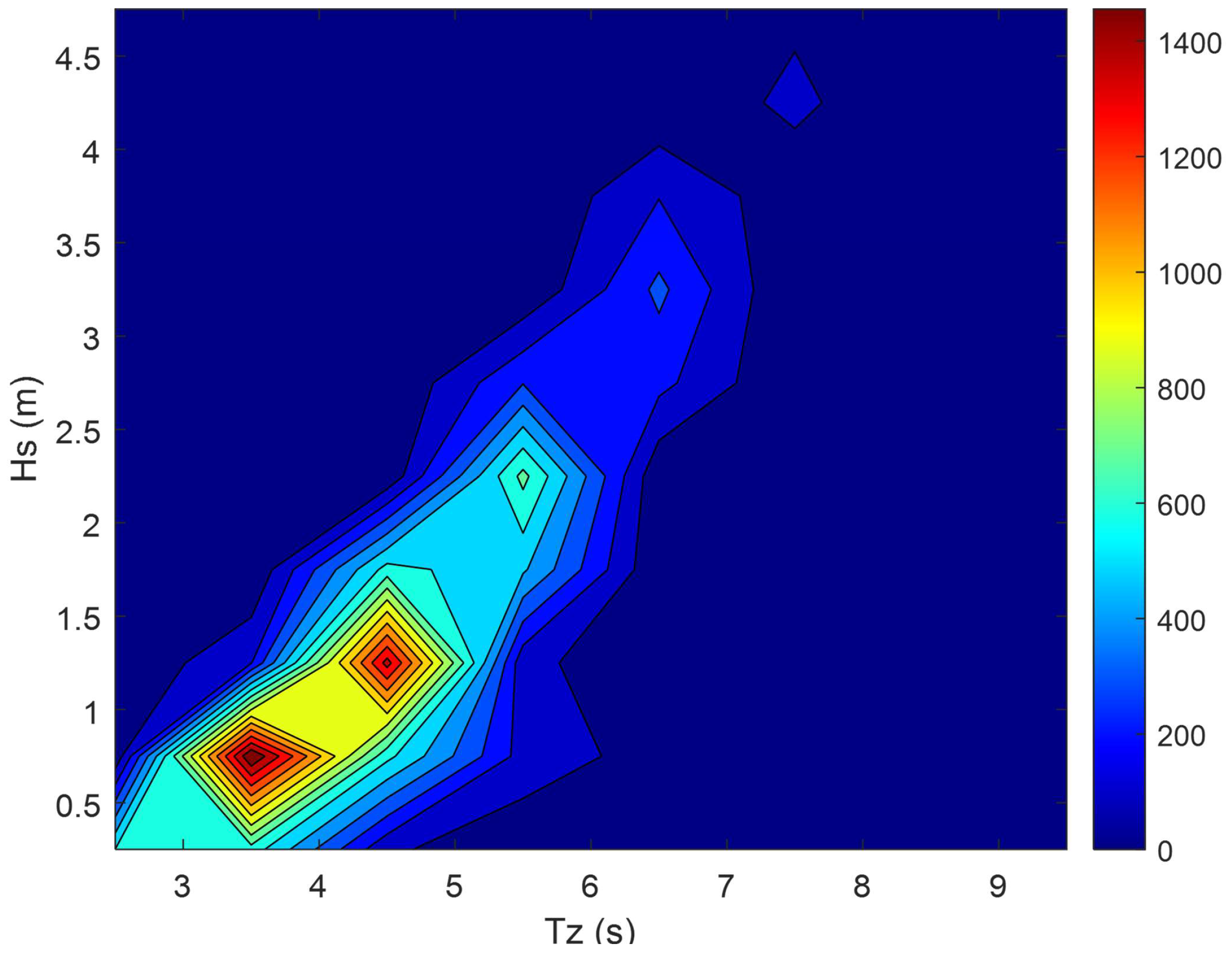
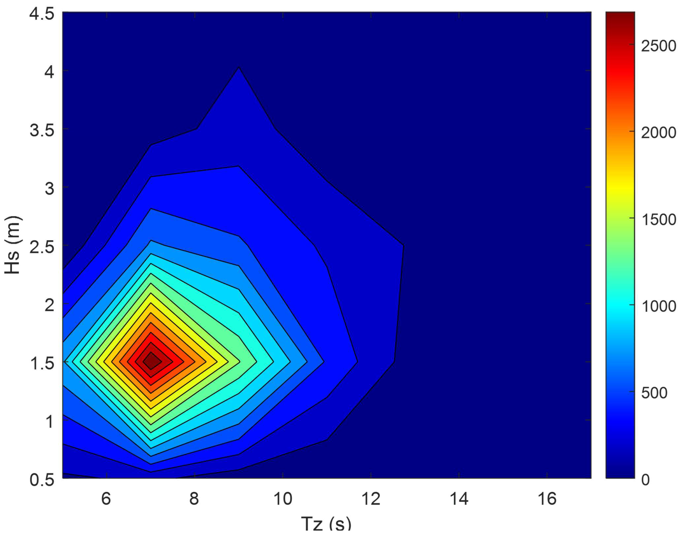
where η is the generator efficiency; A is the availability of WECs to work, and it is set as 90% due to necessary operation and maintenance [47]; T represents the total hours of the occurrence of a certain sea state and x means the wave state. The sea site is considered as Yeu island situated in the oceanic territory of France, and its hours of occurrence of each wave state are shown in Appendix A. By equating the time-averaged power transport per unit length of the wavefront of the incoming waves, the irregular wave states are converted to regular wave states for the sake of simplification [9]. The LCOE of a WEC can be expressed as
LCOE = CAPEX + Y = 1 N OPEX Y ( 1 + r ) Y Y = 1 n AEP Y ( 1 + r ) Y
in which CAPEX and OPEX represent the Capital Expenditure (CAPEX) and the Operational Expenditure (OPEX), respectively. The annual OPEX is assumed to be 8% of the CAPEX; r, N and Y embody the discount rate, the lifespan and the evaluated year. The CAPEX of a WEC can be derived as
CAPEX = C S + C F + C I + C pto + C C
where C S , C F , C I , C pto and C C are the costs of the structure, foundation and mooring, installation, PTO and grid connection, respectively. C S , C F and C I are related to the structural mass of the system. They are estimated using the method introduced in [9]. As for the linear generator, the costs are predicted as
C pto = 2 ( C F e M F e + C C u M C u + C p m M p m )
In Equation (30), a factor of 2 is included to cover the costs of manufacturing and converter; C F e , C C u and C p m embody the cost of iron, copper and the permanent magnet per unit mass, and their values are referred to [48]; M F e , M C u and M p m are the mass of iron, copper and permanent magnet, respectively. The relevant economic parameters applied in this work are listed in Table 3.
It should be acknowledged that only a simplified economic model is applied in this work. The economic parameters can be affected by a variety of factors, but the influence of economic modeling on the generator sizing of the WEC is not taken into consideration. The method used here is limited to this specific type of WEC and a single device. For instance, the economic parameters might be different for WEC farms. Because the operation and maintenance strategy could be optimized for WEC farms to better compromise the availability of the WEC and the total OPEX [50]. Then, the estimation of the OPEX has to be updated. Besides, the cost of the WEC structure and the PTO could be decreased when entering into the stage of series manufacture for WEC farms. Moreover, it can be expected that the lifespan and the operational demand of the WECs are correlated with the local wave climate [51]. For example, the frequent occurrence of harsh wave conditions has a negative influence on the lifespan of the WEC. This implies that the economic parameters could differ with the wave site where the WEC is considered to be deployed. Furthermore, a common challenge in modeling the economics of WECs results from the lack of information of the practical projects, which causes the disagreement of economic parameters in different references. Nevertheless, given the scope of this work is to identify the effect of the generator sizing on the performance, it is thought reasonable at the current stage to use this model for constructing an economic implication.

5. Results and Discussion

5.1. Generator Performance

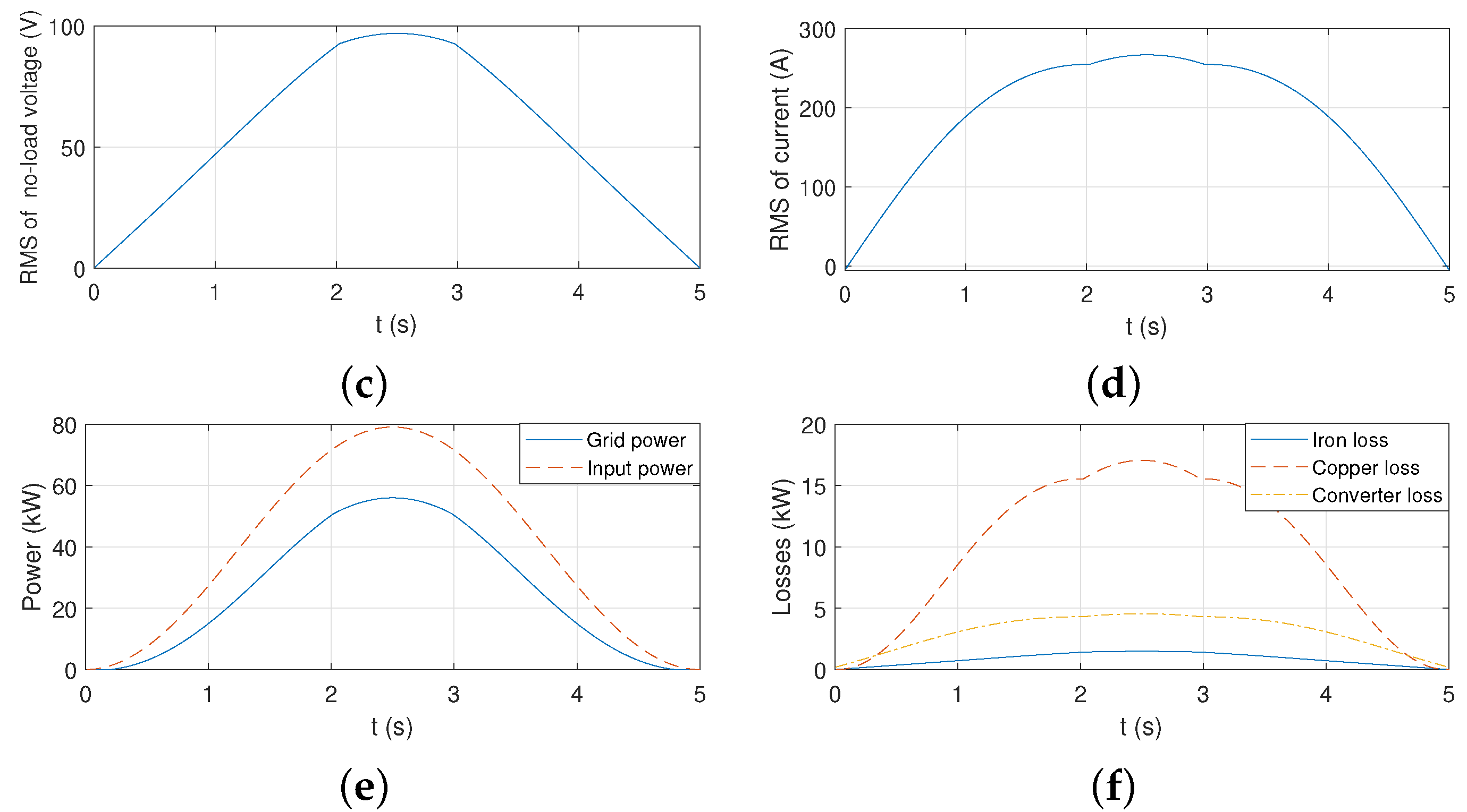
The performance of the linear PM generator is calculated for a particular regular wave state, which is depicted in Figure 4. The concerned generator is sized by method 2 with a maximum designed generator force of 200 kN, and the resized parameters will be shown in Figure 5 and discussed in the following text. It is seen from Figure 4 that the root mean square (RMS) of the no-load voltage doesn’t present a sinusoidal curve, which results from the partial overlap between the translator and stator. A negative effect of the partial overlap can be observed as that the stator current is driven relatively higher for maintaining the required generator force. Consequently, the copper and converter losses are also increased.

5.2. Comparison of Sizing Methods

5.2.1. On the Generator Performance

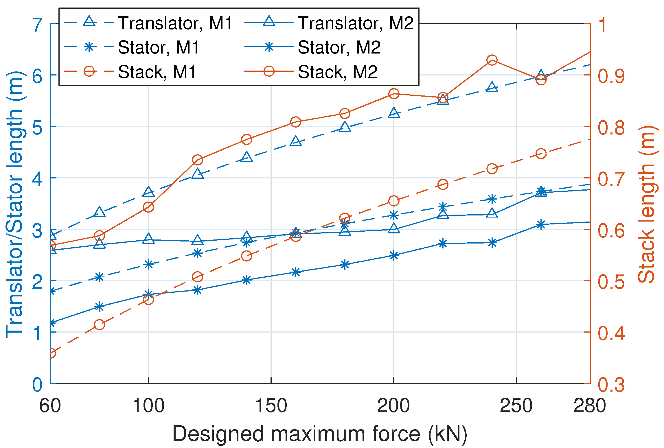
The reference linear generator is resized corresponding to the designed maximum generator forces ranging from 60 kN to 280 kN. The machine parameters scaled by method 1 and method 2 are compared in Figure 5. It can be seen that all of the translator, stator and stack lengths show a trend to increase with the designed maximum generator force regardless of the sizing method. However, these two methods result in very different machine parameters. The stack lengths obtained using method 2 are clearly longer than those by method 1, but the translator and stator lengths resulting from method 2 are shorter. Noteworthy, based on method 2, the length difference between the translator and the stator is limited if compared to the cases using method 1. This indicates that the negative effect of the partial overlap is not significant for the combination of the machine and the considered wave resource. This can be interpreted as the fact the displacement of the WEC is relatively small in the wave states dominating energy production.
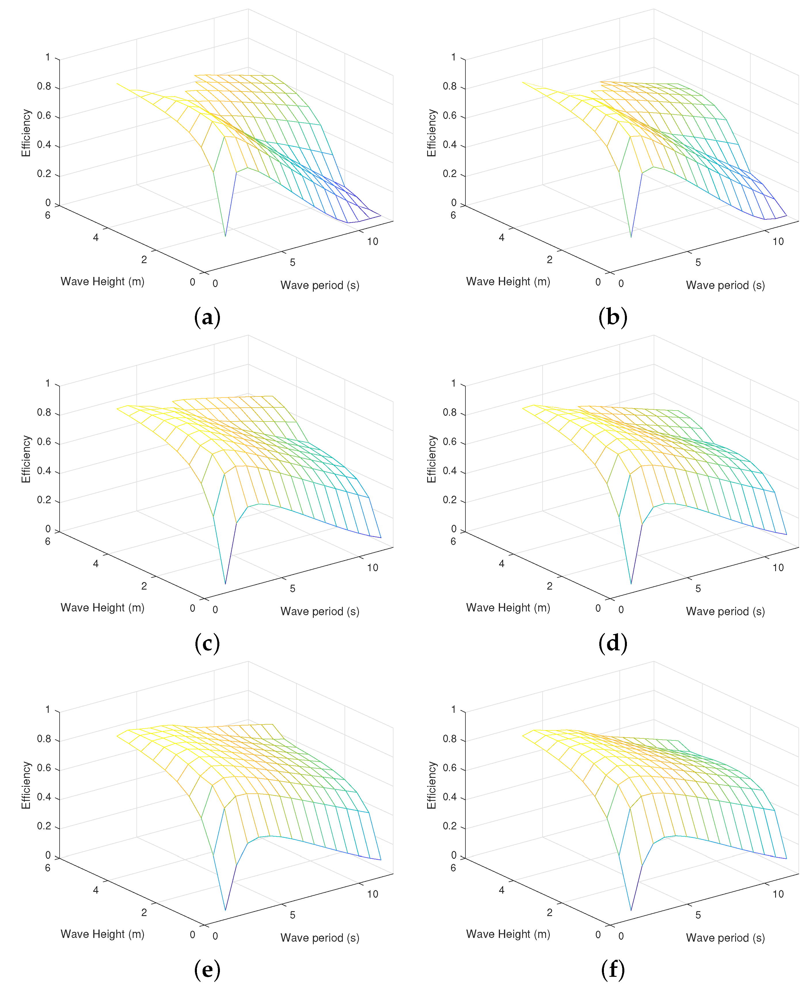
Figure 6 shows the efficiency maps of linear generators with the designed maximum force of 100 kN, 160 kN and 200 kN, respectively, in which regular wave states are considered. Sizing method 1 and method 2 are both applied for comparison. The efficiency at each wave state is calculated as the ratio between the electrical power and the absorbed power of the floater. It is visible in Figure 6 that larger generators generally correspond to higher efficiencies. Besides, the efficiency tends to increase with the wave height and decline with the wave period. For the generator with a designed maximum force of 100 kN, a few empty cells can be noticed at low wave periods and very high wave heights. This is because the buoy velocity tends to be high in these operating conditions. Then, the PTO damping has to be increased to lower the velocity, but the larger PTO damping values are necessarily related to the larger PTO force. Therefore, with a relatively strict designed maximum force, it is not feasible to satisfy both the defined force constraint and velocity constraint.
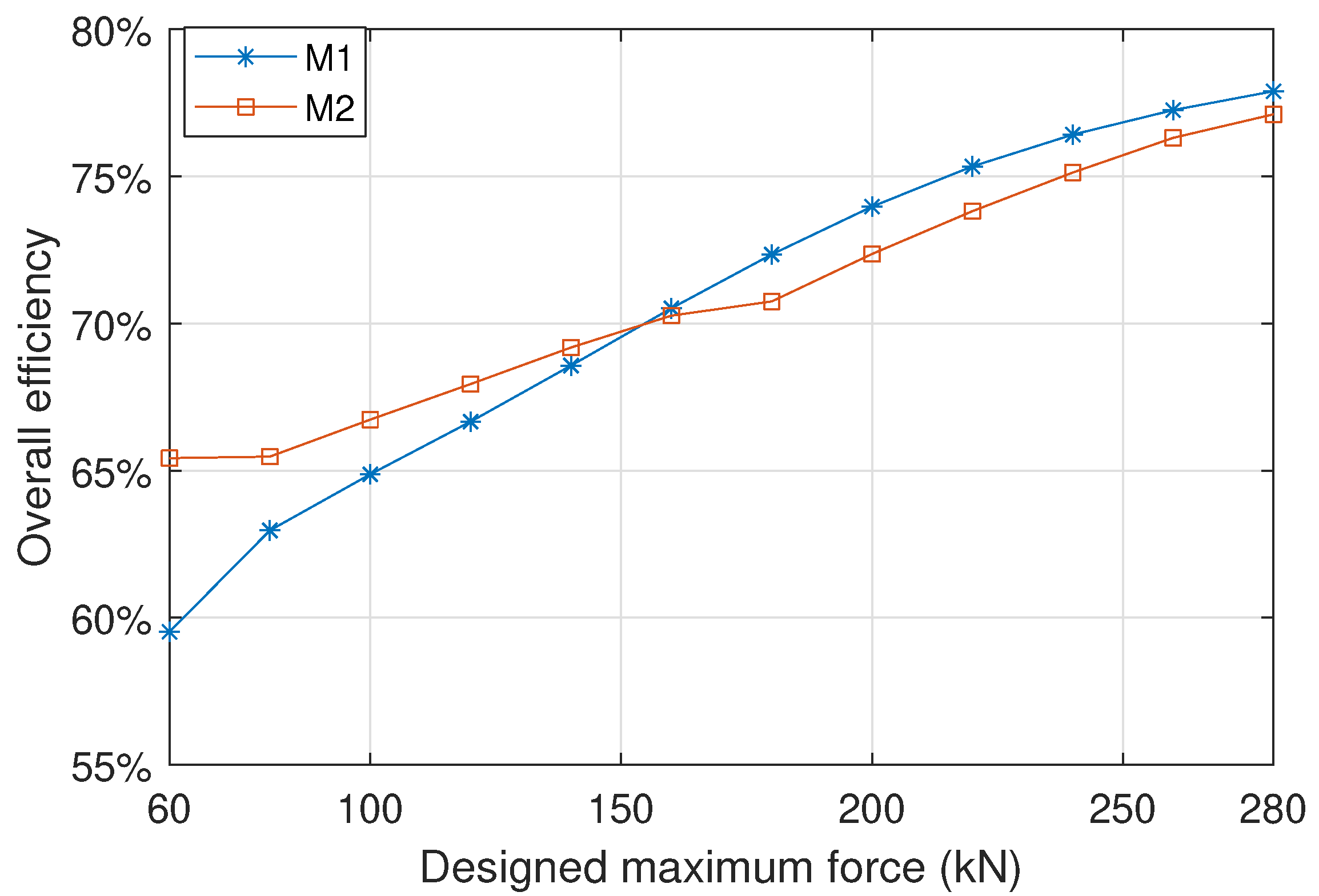
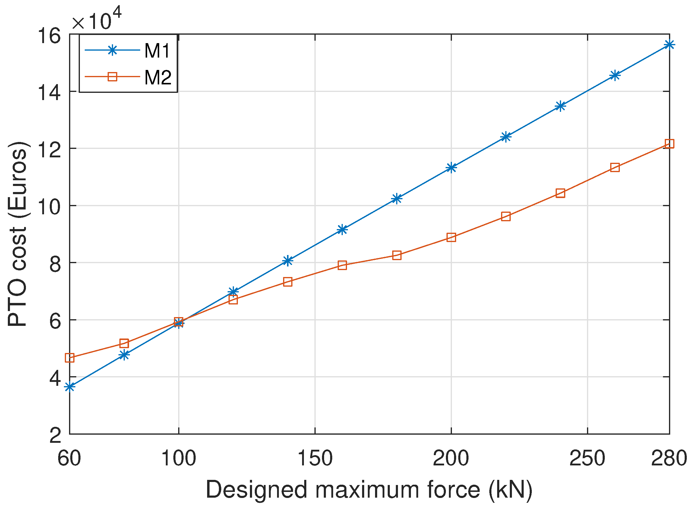
The overall conversion efficiencies of the generators operating in Yeu island are shown in Figure 7, which is defined as the ratio between the yearly electrical power production and the yearly energy absorbed by the buoy. First, the overall efficiency has a clear dependence on the generator size no matter which sizing method is applied. Generally, larger generators present higher conversion efficiencies. In this particular case, the overall conversion efficiencies are around 60% to 65% for the generator sized with a designed maximum force of 60 kN, while they increase to be higher than 75% for generators with a designed maximum force of 280 kN. This observation clearly reflects the inaccuracy of the assumption used in previous sizing studies [9,14,52] that the generator efficiency is not changing during PTO sizing. Secondly, even though the optimization procedure is incorporated in method 2, it does not necessarily lead to a higher efficiency. For instance, the overall efficiency of the generator scaled based on method 2 is associated with slightly lower efficiency compared to that using method 1 when the designed maximum force is larger than 250 kN. Nevertheless, the contribution of the optimization can be found in Figure 8 as method 2 gives a lower PTO cost when the designed maximum force is higher than 100 kN. For instance, the PTO cost of the generator with a designed maximum force of 280 kN is 160,000 Euros and 12,000 Euros for method 1 and 2, respectively, while their generator efficiencies are comparable.

5.2.2. On the Techno-Economics and the PTO Size Determination

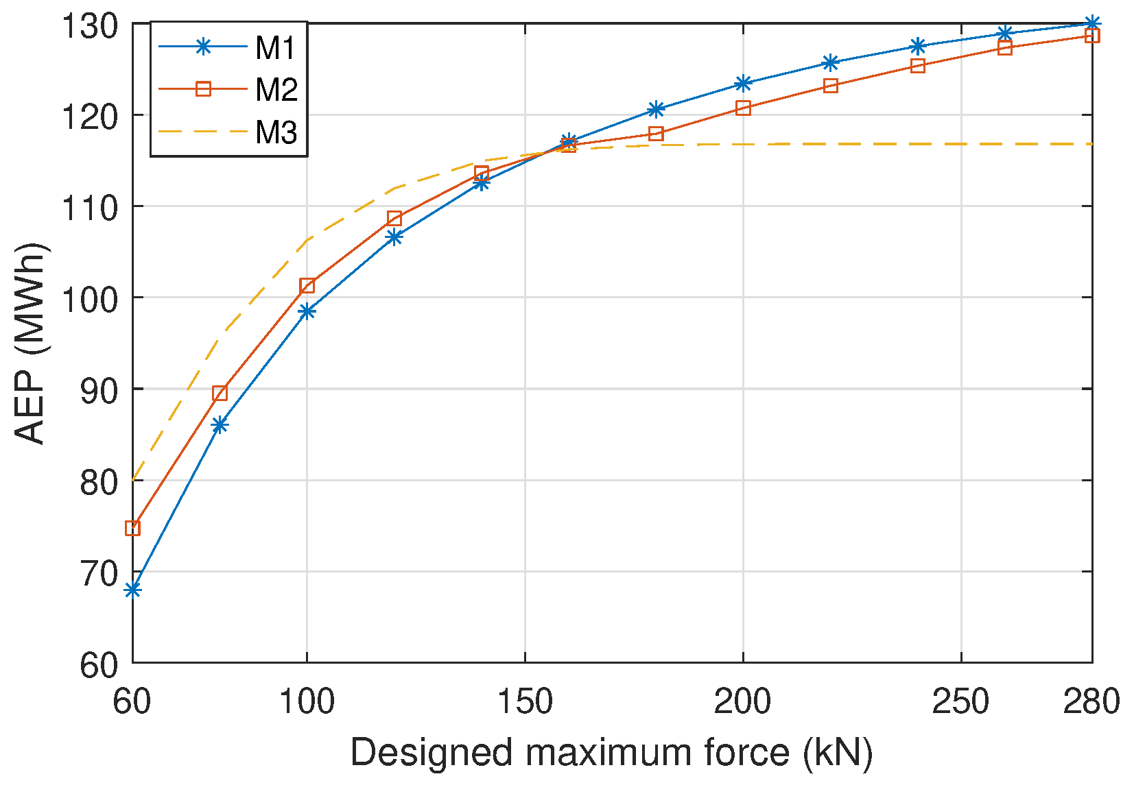
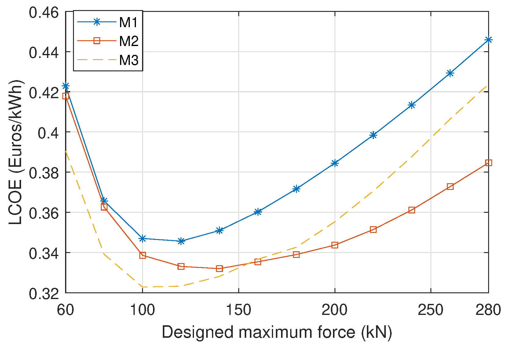
The AEP and the LCOE of the WEC with differently sized generators are depicted in Figure 9 and Figure 10, in which three different sizing methods are applied, respectively. From Figure 9, it is visible that the method 1 and method 2 result in similar values of the AEP, but the relative discrepancy of method 3 is noticeable. For example, when the designed maximum force is 280 kN, the AEP is approximately 130 MWh for method 1 and method 2, but the AEP is calculated to be around 117 MWh by using method 3. In this sense, the relative error reaches 10%. However, unlike the trends of the AEP, these three methods result in very different values of the LCOE, as shown in Figure 10. For instance, when the designed maximum force of the generator is 280 kN, the LCOE is estimated to be around 0.45 Euros, 0.38 Euros and 0.42 Euros for the method 1, 2 and 3, respectively. In this sense, the optimization of generator parameters leads to the reduction of the LCOE of around 15% and 10% with regard to method 1 and 3. In addition, as a consequence of the optimization of the main parameters, method 2 is always related to a lower value of the LCOE compared to method 1. Furthermore, the selection of the generator sizing method is significant to the PTO size determination. In this case, the optimal PTO force limit corresponding to the lowest LCOE is 120 kN, 140 kN and 100 kN for method 1, 2 and 3, respectively. In this sense, the relative error resulting from the assumption of a constant generator efficiency on the PTO size determination is around 29%. It can be concluded that method 3, which assumes the constant generator efficiency during sizing, could lead to a notable misestimate of the AEP, LCOE and the optimal PTO size. Thus, taking the influence of sizing on the generator efficiency into consideration is strongly suggested when conducting PTO sizing. Method 2, namely scaling with the optimization of the main parameters, could better reflect the techno-economic potential of the WEC, since it presents a lower LCOE compared to method 1, which is based on the scaling law. However, it has to be acknowledged that the optimization requires higher computational efforts, while the scaling law requires negligible computational loads with a given reference machine.

5.3. Dependence of the Generator Sizing on Wave Resources

To demonstrate the dependence of the generator sizing and techno-economic performance of the WEC on different characteristics of wave resources, two more wave sites are considered as a comparison in this subsection. They are DK North Sea Point 2 (DK2) and Biscay Marine Energy Park (BIMEP), located in the oceanic territories of Denmark and Spain, respectively. Their scatter diagrams are shown in Appendix A. The mean wave power density of Yeu island, DK 2 and BIMEP are 26 kW/m, 12 kW/m and 21 kW/m, respectively. Only method 2 is applied in this subsection for PTO sizing. Figure 11a shows the optimized design parameters of the linear generator in different wave sites, and the parameters are normalized to the optimized values for Yeu island. It can be found that the wave resource makes a difference to the optimization of the design parameters.
Figure 11b shows the overall efficiencies of the differently sized linear generators in the three wave sites. It can be seen that the overall efficiency is highly related to the wave resource. The overall efficiencies in Yeu island and DK 2 are clearly higher than that in BIMEP. For instance, when the designed maximum generator force is 60 kN, the efficiencies in Yeu island and DK 2 are around 65% while it is only 45% in BIMEP. This can be explained by the fact that the wave states in BIMEP are concentrated in relatively long wave periods, which are associated with low translator velocities. Therefore, the generator efficiency is not only dependent on the generator size but also to the wave resource, and it is unrealistic to be represented by a constant value. Figure 11c depicts the LCOE of WECs in different wave sites. It is visible that the value of the LCOE clearly differs with the wave site. For instance, when the designed maximum force is 100 kN, the values of the LCOE in Yeu island, DK 2 and BIMEP are estimated to be around 0.33, 0.52 and 0.67 Euros/kWh, respectively. The reason is that the energy production of the WEC varies in different wave sites. The difference of wave resources in each site is reflected by its specific distribution of the occurrence of wave states. The distribution of the considered three wave sites are clearly different, as presented in Appendix A. However, the power absorption of a WEC is highly dependent on the wave state, since the wave period and height are crucial to the dynamics of the buoy [53,54]. In addition to the power absorption stage, the generator efficiency also presents a strong relation to the wave state because of the variation of the translator velocity and displacement, as shown in Figure 6. Therefore, it is reasonable that there appears a difference in the LCOE in the three wave sites. It also implies the importance of wave resource of deployment on the techno-economic performance of the WEC. In this case, the LCOE in Yeu island is the lowest among the three. The LCOE in DK 2 is lower than that in BIMEP while BIMEP corresponds to a higher mean wave power density. Hence, more powerful wave resources do not necessarily contribute to better techno-economic performance. Furthermore, the optimal generator size differs with wave resources. The lowest LCOE values in Yeu island, DK 2 and BIMEP correspond to the designed maximum generator force of 120 kN, 100 kN and 160 kN, respectively.

6. Conclusions

The influence of PTO sizing on the power conversion efficiency of a linear generator in a point absorber WEC is investigated in this work. The relevance of PTO sizing to the techno-economic performance of WECs is also studied. To estimate the power production of WECs with the variously sized PTO systems, hydrodynamic modeling and generator modeling are both taken into consideration. Different methods are applied for sizing the linear PM generator for various designed maximum generator forces. Based on the results, it is concluded that the sizing of the generator is important to the LCOE of WECs. The overall conversion efficiency has a notable dependence on the size of generators. Thus, assuming a constant generator efficiency causes an obvious mis-estimate on the determination of the AEP, LCOE and the PTO capacity. In particular cases, the relative errors in the estimation of the AEP and the optimal PTO capacity reach 10% and 29%. Compared with the method based on the scaling law, the scaling with implementing the optimization of main machine parameters could better reflect the techno-economic potential of WECs when conducting PTO sizing. Moreover, the overall generator efficiency and the LCOE are notably related to the wave resource. The wave resource has a clear influence on the LCOE and overall efficiencies of the linear generator. As the overall efficiency of the generator is far from being constant, it is important to take the variation of the generator performance into consideration when sizing PTO systems of WECs for different sea sites.

Author Contributions

Conceptualization, J.T., X.W. and H.P.; methodology, J.T., X.W. and H.P.; software, J.T.; validation, H.P.; formal analysis, J.T., X.W., A.J.L., H.P. and S.A.M.; investigation, J.T., X.W., A.J.L., H.P. and S.A.M.; resources, J.T., X.W., A.J.L., H.P. and S.A.M.; data curation, J.T., X.W., A.J.L., H.P. and S.A.M.; writing—original draft preparation, J.T.; writing—review and editing, J.T., X.W., A.J.L., H.P. and S.A.M.; visualization, J.T.; supervision, A.J.L., H.P. and S.A.M.; project administration, A.J.L., H.P. and S.A.M.; funding acquisition, A.J.L., H.P. and S.A.M. All authors have read and agreed to the published version of the manuscript.

Funding

This research has received funding from China Scholarship Council under Grant: 20180695 0003.

Institutional Review Board Statement

Not applicable.

Informed Consent Statement

Not applicable.

Data Availability Statement

The data presented in this study are available on request from the corresponding author.

Conflicts of Interest

The authors declare no conflict of interest.

Appendix A

The scatter diagrams of wave states in Yeu island, DK 2 and BIMEP are shown below.
Figure A1. Hours of occurrence of each wave state of Yeu island [54].
Jmse 10 01316 g0a1
Figure A2. Hours of occurrence of each wave state of DK 2 [14].
Jmse 10 01316 g0a2
Figure A3. Hours of occurrence of each wave state of BIMEP [14].
Jmse 10 01316 g0a3

References

  1. Tan, J.; Wang, X.; Jarquin Laguna, A.; Polinder, H.; Miedema, S. The Influence of Linear Permanent Magnet Generator Sizing on the Techno-Economic Performance of a Wave Energy Converter. In Proceedings of the 2021 13th International Symposium on Linear Drives for Industry Applications (LDIA), Wuhan, China, 1 July 2021; pp. 1–6. [Google Scholar] [CrossRef]
  2. Ahamed, R.; McKee, K.; Howard, I. Advancements of wave energy converters based on power take off (PTO) systems: A review. Ocean. Eng. 2020, 204, 107248. [Google Scholar] [CrossRef]
  3. Aderinto, T.; Li, H. Ocean Wave energy converters: Status and challenges. Energies 2018, 11, 1250. [Google Scholar] [CrossRef]
  4. Shen, W.; Chen, X.; Qiu, J.; Hayward, J.A.; Sayeef, S.; Osman, P.; Meng, K.; Dong, Z.Y. A comprehensive review of variable renewable energy levelized cost of electricity. Renew. Sustain. Energy Rev. 2020, 133, 110301. [Google Scholar] [CrossRef]
  5. Lavidas, G.; Blok, K. Shifting wave energy perceptions: The case for wave energy converter (WEC) feasibility at milder resources. Renew. Energy 2021, 170, 1143–1155. [Google Scholar] [CrossRef]
  6. Iglesias, G.; Astariz, S.; Vazquez, A. The economics of wave and tidal energy. Wave Tidal Energy 2018, 513–532. [Google Scholar] [CrossRef]
  7. Wang, L.; Zhao, T.; Lin, M.; Li, H. Towards realistic power performance and techno-economic performance of wave power farms: The impact of control strategies and wave climates. Ocean Eng. 2022, 248, 110754. [Google Scholar] [CrossRef]
  8. Pecher, A. Handbook of Ocean Wave Energy; Springer: Berlin/Heidelberg, Germany, 2017; Volume 7. [Google Scholar] [CrossRef]
  9. Tan, J.; Polinder, H.; Laguna, A.J.; Wellens, P.; Miedema, S. The Influence of Sizing of Wave Energy Converters on the Techno-Economic Performance. J. Mar. Sci. Eng. 2021, 9, 52. [Google Scholar] [CrossRef]
  10. Tan, J.; Polinder, H.; Wellens, P.; Miedema, S. A feasibility study on downsizing of power take off system of wave energy converters. Dev. Renew. Energies Offshore 2020, 140–148. [Google Scholar] [CrossRef]
  11. Tan, J.; Polinder, H.; Miedema, S. The Fair Evaluation of Wave Energy Converters. In Proceedings of the 39th International Conference on Ocean, Offshore and Arctic Engineering, Online, 3–7 August 2020; Volume 84416, p. V009T09A016. [Google Scholar] [CrossRef]
  12. Tokat, P. Performance Evaluation and Life Cycle Cost Analysis of the Electrical Generation Unit of a Wave Energy Converter; Chalmers Tekniska Hogskola: Göteborg, Sweden, 2018. [Google Scholar]
  13. Cappelli, L.; Marignetti, F.; Mattiazzo, G.; Giorcelli, E.; Bracco, G.; Carbone, S.; Attaianese, C. Linear tubular permanent-magnet generators for the inertial sea wave energy converter. IEEE Trans. Ind. Appl. 2014, 50, 1817–1828. [Google Scholar] [CrossRef]
  14. de Andres, A.; Maillet, J.; Todalshaug, J.H.; Möller, P.; Bould, D.; Jeffrey, H. Techno-economic related metrics for a wave energy converters feasibility assessment. Sustainability 2016, 8, 1109. [Google Scholar] [CrossRef]
  15. Henderson, R. Design, simulation, and testing of a novel hydraulic power take-off system for the Pelamis wave energy converter. Renew. Energy 2006, 31, 271–283. [Google Scholar] [CrossRef]
  16. Wang, L.; Isberg, J.; Tedeschi, E. Review of control strategies for wave energy conversion systems and their validation: The wave-to-wire approach. Renew. Sustain. Energy Rev. 2018, 81, 366–379. [Google Scholar] [CrossRef]
  17. He, X.; Xiao, G.; Hu, B.; Tan, L.; Tang, H.; He, S.; He, Z. The applications of energy regeneration and conversion technologies based on hydraulic transmission systems: A review. Energy Convers. Manag. 2020, 205, 112413. [Google Scholar] [CrossRef]
  18. Golbaz, D.; Asadi, R.; Amini, E.; Mehdipour, H.; Nasiri, M.; Nezhad, M.M.; Naeeni, S.T.O.; Neshat, M. Ocean Wave Energy Converters Optimization: A Comprehensive Review on Research Directions. arXiv 2021, arXiv:2105.07180. [Google Scholar]
  19. Kofoed, J.P.; Frigaard, P.; Friis-Madsen, E.; Sørensen, H.C. Prototype testing of the wave energy converter wave dragon. Renew. Energy 2006, 31, 181–189. [Google Scholar] [CrossRef]
  20. Heath, T.V. A review of oscillating water columns. Philos. Trans. R. Soc. A 2012, 370, 235–245. [Google Scholar] [CrossRef]
  21. Binh, P.C.; Tri, N.M.; Dung, D.T.; Ahn, K.K.; Kim, S.J.; Koo, W. Analysis, design and experiment investigation of a novel wave energy converter. IET Gener. Transm. Distrib. 2016, 10, 460–469. [Google Scholar] [CrossRef]
  22. Wu, J.; Qin, L.; Chen, N.; Qian, C.; Zheng, S. Investigation on a spring-integrated mechanical power take-off system for wave energy conversion purpose. Energy 2022, 245, 123318. [Google Scholar] [CrossRef]
  23. Stansby, P.; Moreno, E.C.; Draycott, S.; Stallard, T. Total wave power absorption by a multi-float wave energy converter and a semi-submersible wind platform with a fast far field model for arrays. J. Ocean. Eng. Mar. Energy 2022, 8, 43–63. [Google Scholar] [CrossRef]
  24. Falcão, A.F.O. Wave energy utilization: A review of the technologies. Renew. Sustain. Energy Rev. 2010, 14, 899–918. [Google Scholar] [CrossRef]
  25. Prado, M.; Polinder, H. Direct Drive Wave Energy Conversion Systems: An Introduction; Woodhead Publishing Limited: Oxford, UK, 2013; pp. 175–194. [Google Scholar] [CrossRef]
  26. Eriksson, M. Modelling and Experimental Verification of Direct Drive Wave Energy Conversion; Chalmers Tekniska Hogskola: Göteborg, Sweden, 2007. [Google Scholar]
  27. Polinder, H.; Damen, M.E.C.; Gardner, F. Linear PM generator system for wave energy conversion in the AWS. IEEE Trans. Energy Convers. 2004, 19, 583–589. [Google Scholar] [CrossRef]
  28. Hong, Y.; Temiz, I.; Pan, J.; Eriksson, M.; Boström, C. Damping Studies on PMLG-Based Wave Energy Converter under Oceanic Wave Climates. Energies 2021, 14, 920. [Google Scholar] [CrossRef]
  29. Elwood, D.; Yim, S.C.; Prudell, J.; Stillinger, C.; von Jouanne, A.; Brekken, T.; Brown, A.; Paasch, R. Design, construction, and ocean testing of a taut-moored dual-body wave energy converter with a linear generator power take-off. Renew. Energy 2010, 35, 348–354. [Google Scholar] [CrossRef]
  30. Faiz, J.; Nematsaberi, A. Linear permanent magnet generator concepts for direct-drive wave energy converters: A comprehensive review. In Proceedings of the 2017 12th IEEE Conference on Industrial Electronics and Applications, Siem Reap, Cambodia, 18–20 June 2017; pp. 618–623. [Google Scholar] [CrossRef]
  31. Shuheng, Q.; Haifeng, W. Simulation of Tubular Transverse Flux Permanent Magnet Linear Generator. In Proceedings of the 2018 21st International Conference on Electrical Machines and Systems (ICEMS), Jeju, Korea, 7–10 October 2018; pp. 1766–1770. [Google Scholar] [CrossRef]
  32. Chen, M.; Huang, L.; Hu, M.; Hu, B.; Ahmad, G. A Spiral Translator Permanent Magnet Transverse Flux Linear Generator Used in Direct Drive Wave Energy Converter. IEEE Trans. Magn. 2021, 57, 1–5. [Google Scholar] [CrossRef]
  33. Chen, M.; Huang, L.; Li, Y.; Tan, P.; Ahmad, G.; Liu, Y.; Hu, M. Analysis of Magnetic Gearing Effect in Field-modulated Transverse Flux Linear Generator for Direct Drive Wave Energy Conversion. IEEE Trans. Magn. 2021, 58, 1–5. [Google Scholar] [CrossRef]
  34. Liu, Z.; Wang, X.; Al Shami, E.; Baker, N.J.; Ji, X. A study of a speed amplified linear generator for low-frequency wave energy conversion. Mech. Syst. Signal Process. 2021, 149, 107226. [Google Scholar] [CrossRef]
  35. Jing, H.; Maki, N.; Ida, T.; Izumi, M. Electromechanical design of an MW class wave energy converter with an HTS tubular linear generator. IEEE Trans. Appl. Supercond. 2018, 28, 1–4. [Google Scholar] [CrossRef]
  36. Keysan, O.; Mueller, M.A. A linear superconducting generator for wave energy converters. In Proceedings of the 6th IET International Conference on Power Electronics, Machines and Drives (PEMD 2012), Bristol, UK, 27–29 March 2012; pp. 1–6. [Google Scholar] [CrossRef]
  37. Jing, H.; Maki, N.; Ida, T.; Izumi, M. Design study of large-scale HTS linear generators for wave energy conversion. IEEE Trans. Appl. Supercond. 2017, 27, 1–5. [Google Scholar] [CrossRef]
  38. Polinder, H.; Damen, M.E.; Gardner, F. Design, modelling and test results of the AWS PM linear generator. Eur. Trans. Electr. Power 2005, 15, 245–256. [Google Scholar] [CrossRef]
  39. Prado, M.; Polinder, H. Case Study of the Archimedes Wave Swing (AWS) Direct Drive Wave Energy Pilot Plant; Woodhead Publishing Limited: Oxford, MI, USA, 2013; pp. 195–218. [Google Scholar] [CrossRef]
  40. Polinder, H. Principles of Electrical Design of Permanent Magnet Generators for Direct Drive Renewable Energy Systems; Woodhead Publishing Limited: Oxford, MI, USA, 2013; pp. 30–50. [Google Scholar] [CrossRef]
  41. Falnes, J.; Kurniawan, A. Ocean Waves and Oscillating Systems: Linear Interactions Including Wave-Energy Extraction; Cambridge University Press: Cambridge, UK, 2020. [Google Scholar] [CrossRef]
  42. Penalba, M.; Kelly, T.; Ringwood, J.V. Using NEMOH for Modelling Wave Energy Converters: A Comparative Study with WAMIT. In Proceedings of the 12th European Wave and Tidal Energy Conference, Cork, Ireland, 27 August–1 September 2017; p. 10. [Google Scholar]
  43. Shek, J.K.; Macpherson, D.E.; Mueller, M.A. Experimental verification of linear generator control for direct drive wave energy conversion. IET Renew. Power Gener. 2010, 4, 395–403. [Google Scholar] [CrossRef]
  44. Polinder, H.; Van Der Pijl, F.F.; De Vilder, G.J.; Tavner, P.J. Comparison of direct-drive and geared generator concepts for wind turbines. IEEE Trans. Energy Convers. 2006, 21, 725–733. [Google Scholar] [CrossRef] [Green Version]
  45. Queipo, N.V.; Haftka, R.T.; Shyy, W.; Goel, T.; Vaidyanathan, R.; Tucker, P.K. Surrogate-based analysis and optimization. Prog. Aerosp. Sci. 2005, 41, 1–28. [Google Scholar] [CrossRef]
  46. De Andres, A.; Medina-Lopez, E.; Crooks, D.; Roberts, O.; Jeffrey, H. On the reversed LCOE calculation: Design constraints for wave energy commercialization. Int. J. Mar. Energy 2017, 18, 88–108. [Google Scholar] [CrossRef]
  47. Kramer, M.M.; Marquis, L.; Frigaard, P. Performance Evaluation of the Wavestar Prototype. In Proceedings of the 9th European Wave and Tidal Conference, Southampton, UK, 5–9 September 2011; pp. 5–9. [Google Scholar]
  48. Tokat, P.; Thiringer, T. Sizing of IPM Generator for a Single Point Absorber Type Wave Energy Converter. IEEE Trans. Energy Convers. 2018, 33, 10–19. [Google Scholar] [CrossRef]
  49. Tan, J.; Polinder, H.; Laguna, A.J.; Miedema, S. The application of the spectral domain modeling to the power take-off sizing of heaving wave energy converters. Appl. Ocean Res. 2022, 122, 103110. [Google Scholar] [CrossRef]
  50. Rinaldi, G.; Portillo, J.; Khalid, F.; Henriques, J.; Thies, P.; Gato, L.; Johanning, L. Multivariate analysis of the reliability, availability, and maintainability characterizations of a Spar–Buoy wave energy converter farm. J. Ocean Eng. Mar. Energy 2018, 4, 199–215. [Google Scholar] [CrossRef]
  51. López-Ruiz, A.; Bergillos, R.J.; Lira-Loarca, A.; Ortega-Sánchez, M. A methodology for the long-term simulation and uncertainty analysis of the operational lifetime performance of wave energy converter arrays. Energy 2018, 153, 126–135. [Google Scholar] [CrossRef]
  52. Majidi, A.G.; Bingölbali, B.; Akpınar, A.; Iglesias, G.; Jafali, H. Downscaling wave energy converters for optimum performance in low-energy seas. Renew. Energy 2021, 168, 705–722. [Google Scholar] [CrossRef]
  53. Babarit, A. A database of capture width ratio of wave energy converters. Renew. Energy 2015, 80, 610–628. [Google Scholar] [CrossRef]
  54. Babarit, A.; Hals, J.; Muliawan, M.J.; Kurniawan, A.; Moan, T.; Krokstad, J. Numerical benchmarking study of a selection of wave energy converters. Renew. Energy 2012, 41, 44–63. [Google Scholar] [CrossRef]
Figure 1. Schematic of the heaving point absorber WEC, and the connection scheme of the PM linear generator with the back-to-back converter and the grid.
Jmse 10 01316 g001
Figure 2. The photo of the reference linear electrical machine in the pilot of the AWS WEC, and the cross-section of the linear PM generator of the AWS plant. In figure (b), a/a’, b/b’ and c/c’ are the current directions [39], and the "z" axis in the coordinate is perpendicular to the ground plane. (a) Photo of the reference machine. (b) Cross-Section of the machine.
Jmse 10 01316 g002
Figure 3. Equivalent circuit and the phasor diagram of the linear generator.
Jmse 10 01316 g003
Figure 4. Generator performance over a half of wave period with a displacement of 0.85 m and a wave period of 10.0 s. The considered machine is sized with a maximum designed generator force of 200 kN based on sizing method 2. (a) Position and speed of the translator. (b) Instantaneous no-load voltage induced by the translator. (c) RMS value of the no-load voltage. (d) RMS value of the stator current. (e) Input mechanical power and electrical power to the grid. (f) Electrical losses.
Jmse 10 01316 g004aJmse 10 01316 g004b
Figure 5. Scaled translator, stator and stack lengths for different designed maximum generator forces. “M1” and “M2” embody method 1 and method 2 for generator sizing.
Jmse 10 01316 g005
Figure 6. Comparison between efficiency maps of generators scaled based on different methods. (a) Designed maximum force is 100 kN, based on method 1. (b) Designed maximum force is 100 kN, based on method 2. (c) Designed maximum force is 160 kN, based on method 1. (d) Designed maximum force is 160 kN, based on method 2. (e) Designed maximum force is 200 kN, based on method 1. (f) Designed maximum force is 200 kN, based on method 2.
Jmse 10 01316 g006
Figure 7. Scaled translator, stator and stack lengths for different designed maximum generator forces.
Jmse 10 01316 g007
Figure 8. The PTO related cost of generators scaled by different methods.
Jmse 10 01316 g008
Figure 9. The AEP of the WEC as a function of the designed maximum generator force. “M3” embodies the method 3 for generator sizing.
Jmse 10 01316 g009
Figure 10. The LCOE of the WEC as a function of the designed maximum generator force.
Jmse 10 01316 g010
Figure 11. The optimized design parameters, the overall efficiency and the LCOE of the WEC with various designed maximum forces in three different wave sites. (a) The optimized design parameters for DK 2 and BIMEP, which are normalized to the corresponding values in Yeu island. (b) The overall efficiency of the linear generator as a function of the designed maximum generator force. (c) The LCOE of the WEC as a function of the designed maximum generator force.
Jmse 10 01316 g011
Table 1. WECs applying the linear generator tested in the oceanic environment.
ParametersAWSUppsala ConceptSeaBeavI
Rated power2 MW10 kW10 kW
WEC typeSubmerged point absorberFloating point absorberFloating point absorber
Generator structureBottom foundedBottom foundedFloating
Generator topologyFlat and double sidedFlat and four sidedTubular
First tested time200420062007
Testing sitePortugalSwedenUSA
Table 2. Design parameters of the reference linear generator.
ParametersSymbolValue
Maximum average power P r a r e d 1 MW
Maximum force F m a x 933 kN
Maximum velocity u m a x 2.2 m/s
StrokeS7 m
Translator length L t 8 m
Stator length L s 5 m
Air gap lengthg5 mm
Slot width b s 15 m
Stack length l s 1 m
Magnet pole width b p 79 mm
Tooth width b t 19 mm
Magnet thickness l m 15 mm
Number of conductors per slot N s 6
Table 3. Parameters in the economic modeling [14,48,49].
ParameterValueUnit
Iron price ( C F e )3.3Euros/kg
Copper price ( C C u )15.2Euros/kg
Permanent magnet price ( C p m )24.7Euros/kg
Lifespan (N)20years
Discount rate (r)8%
Availability of operation (A)0.9
Publisher’s Note: MDPI stays neutral with regard to jurisdictional claims in published maps and institutional affiliations.