
Enabling Underwater Wireless Power Transfer towards Sixth Generation (6G) Wireless Networks: Opportunities, Recent Advances, and Technical Challenges

 ,
,  ,
,  ,
,  and
and 
Abstract
:1. Introduction
Wireless Power Transfer
- What is the impact of a highly conducting water environment on the electrical parameters of the WPT system?
- How does seawater affect coil radiation resistance?
- What are the losses incurred in UWPT and what are the possible mitigative solutions?
- In the case of highly frequency dependent loss, how to choose the operating frequency to empower an efficient UWPT system?
2. Related Works
3. Wireless Power Transfer Techniques
3.1. Radiative WPT
3.2. Optical Wireless Power Transfer (OWPT)
3.3. Acoustic Power Transfer (APT)
3.4. Nonradiative WPT
3.5. IWPT
3.6. MIMO WPT
4. Practical Considerations and Research Challenges
4.1. Coil Characteristics
4.1.1. Coils Shape
4.1.2. Coil Orientation
4.1.3. Coil Topology
4.2. Frequency Tracking
5. Seawater Effects on WPT
5.1. Water Conductivity
5.2. Ocean Current Disturbance
5.3. Loss and Biofouling
5.4. Temperature and Pressure
6. Engineering Challenges in UWPT Systems
6.1. IWPT System for AUV
6.2. Pressure-Tolerant Electronics
6.3. Retention and Alignment
6.4. Angle Coverage
6.5. Transmitter and Receiver Distance
6.6. Docking Station Stability
6.7. Harsh Envirnment
6.8. Battery Charging Rate
6.9. Security and Pollution Issues
6.10. Auxiliary System Improvement
6.11. Accurate Measurement of Eddy Current Losses in Seawater
6.12. Ambiguity of WPT in Underwater Electric-Field Coupled Power Transfer (ECPT)
6.13. Difficulty of Parameters Configuration in Compensation Net
6.14. Insufficient Power Transfer Efficiency and Intensity
7. Applications
7.1. Mother Ship Charge to AUV
7.2. Designing UWPT for Smart Ocean Energy Systems Applications
7.3. Ocean Observation Network
7.4. Smart Wave Energy Converter (WEC)
7.5. Torpedo AUVs
7.6. Deep-Sea Power and Communication Links
8. Conclusions and Future Work
Author Contributions
Funding
Institutional Review Board Statement
Informed Consent Statement
Data Availability Statement
Conflicts of Interest
References
- Miller, J.M.; Jones, P.T.; Li, J.M.; Onar, O.C. ORNL experience and challenges facing dynamic wireless power charging of EV’s. IEEE Circuits Syst. Mag. 2015, 15, 40–53. [Google Scholar] [CrossRef]
- Li, S.; Mi, C.C. Wireless power transfer for electric vehicle applications. IEEE J. Emerg. Sel. Top. Power Electron. 2015, 3, 4–17. [Google Scholar]
- Campi, T.; Cruciani, S.; de Santis, V.; Palandrani, F.; Maradei, F.; Feliziani, M. Induced Effects in a Pacemaker Equipped with a Wireless Power Transfer Charging System. IEEE Trans. Magn. 2017, 53, 9401704. [Google Scholar] [CrossRef]
- Xu, Q.; Wang, H.; Gao, Z.; Mao, Z.H.; He, J.; Sun, M. A novel mat-based system for position-varying wireless power transfer to biomedical implants. IEEE Trans. Magn. 2013, 49, 4774–4779. [Google Scholar] [CrossRef]
- David, K.; Berndt, H. 6G vision and requirements: Is there any need for beyond 5G? IEEE Veh. Technol. Mag. 2018, 13, 72–80. [Google Scholar] [CrossRef]
- Alsharif, M.H.; Kannadasan, R.; Jahid, A.; Albreem, M.A.; Nebhen, J.; Choi, B.J. Long-term Techno-economic Analysis of Sustainable and Zero Grid Cellular Base Station. IEEE Access 2021, 9, 54159–54172. [Google Scholar] [CrossRef]
- Mshvidobadze, T. Evolution mobile wireless communication and LTE networks. In Proceedings of the 2012 6th International Conference on Application of Information and Communication Technologies (AICT), Tbilisi, Georgia, 17–19 October 2012; IEEE: Piscataway, NJ, USA, 2012. [Google Scholar]
- Alsharif, M.H.; Nordin, R. Evolution towards fifth generation (5G) wireless networks: Current trends and challenges in the deployment of millimetre wave, massive MIMO, and small cells. Telecommun. Syst. 2017, 64, 617–637. [Google Scholar] [CrossRef]
- Mohammed, S.L.; Alsharif, M.H.; Gharghan, S.K.; Khan, I.; Albreem, M. Robust Hybrid Beamforming Scheme for Millimeter-Wave Massive-MIMO 5G Wireless Networks. Symmetry 2019, 11, 1424. [Google Scholar] [CrossRef]
- Alsharif, M.H.; Hossain, M.S.; Jahid, A.; Khan, M.A.; Choi, B.J.; Mostafa, S.M. Milestones of Wireless Communication Networks and Technology Prospect of Next Generation (6G). Comput. Mater. Contin. 2022, 71, 4803–4818. [Google Scholar] [CrossRef]
- Mohsan, S.A.H.; Mazinani, A.; Malik, W.; Younas, I.; Othman, N.Q.H.; Amjad, H.; Mahmood, A. 6G: Envisioning the key technologies, applications and challenges. Int. J. Adv. Comput. Sci. Appl. 2020, 11. [Google Scholar] [CrossRef]
- Alsharif, M.H.; Kelechi, A.H.; Albreem, M.A.; Chaudhry, S.A.; Zia, S.; Kim, S. Sixth Generation (6G) Wireless Networks: Vision, Research Activities, Challenges and Potential Solutions. Symmetry 2020, 12, 676. [Google Scholar] [CrossRef]
- Alsharif, M.H.; Albreem, M.A.; Solyman, A.A.; Kim, S. Toward 6G Communication Networks: Terahertz Frequency Challenges and Open Research Issues. Comput. Mater. Contin. 2020, 66, 2831–2842. [Google Scholar] [CrossRef]
- Mohsan, S.A.H.; Khan, M.A.; Noor, F.; Ullah, I.; Alsharif, M.H. Towards the Unmanned Aerial Vehicles (UAVs): A Comprehensive Review. Drones 2022, 6, 147. [Google Scholar] [CrossRef]
- Wheeb, A.H.; Nordin, R.; Samah, A.A.; Alsharif, M.H.; Khan, M.A. Topology-Based Routing Protocols and Mobility Models for Flying Ad Hoc Networks: A Contemporary Review and Future Research Directions. Drones 2022, 6, 9. [Google Scholar] [CrossRef]
- McEwen, R.S.; Hobson, B.W.; Bellingham, J.G.; McBride, L. Docking control system for a 54-cm-diameter (21-in) AUV. IEEE J. Ocean. Eng. 2008, 33, 550–562. [Google Scholar] [CrossRef]
- Teo, K.; An, E.; Beaujean, P.P.J. A robust fuzzy autonomous underwater vehicle (AUV) docking approach for unknown current disturbances. IEEE J. Ocean. Eng. 2012, 37, 143–155. [Google Scholar] [CrossRef]
- Li, Y.; Jiang, Y.; Cao, J.; Wang, B.; Li, Y. AUV docking experiments based on vision positioning using two cameras. Ocean Eng. 2015, 110, 163–173. [Google Scholar] [CrossRef]
- Zhang, T.; Li, D.; Yang, C. Study on impact process of AUV underwater docking with a cone-shaped dock. Ocean Eng. 2017, 30, 176–187. [Google Scholar] [CrossRef]
- Niu, W.; Gu, W.; Chu, J.; Shen, A. Frequency splitting of underwater wireless power transfer. In Proceedings of the 2016 IEEE International Workshop on Electromagnetics, iWEM, Nanjing, China, 16–18 May 2016. [Google Scholar]
- Hassnain, S.A.; Mughal, M.J.; Naqvi, Q.A. Layered chiral spheres with zero backscattering. In Proceedings of the 2019 Photonics and Electromagnetics Research Symposium-Fall (PIERS-Fall), Xiamen, China, 17–20 December 2019. [Google Scholar]
- Hassnain, S.A.; Mughal, M.J.; Naqvi, Q.A. Analysis of effective medium parameters on polarizability of homogeneous chiral sphere. In Proceedings of the 2019 Photonics and Electromagnetics Research Symposium-Fall (PIERS-Fall), Xiamen, China, 17–20 December 2019. [Google Scholar]
- Kim, J.; Kim, K.; Kim, H.; Kim, D.; Park, J.; Ahn, S. An Efficient Modeling for Underwater Wireless Power Transfer Using Z-Parameters. IEEE Trans. Electromagn. Compat. 2019, 61, 2006–2014. [Google Scholar] [CrossRef]
- Jawad, A.M.; Nordin, R.; Gharghan, S.K.; Jawad, H.M.; Ismail, M. Opportunities and challenges for near-field wireless power transfer: A review. Energies 2017, 10, 1022. [Google Scholar] [CrossRef]
- Zhong, X.; Hui, S.Y.R. Maximum energy efficiency tracking for wireless power transfer systems. IEEE Trans. Power Electron. 2015, 30, 4025–4034. [Google Scholar] [CrossRef] [Green Version]
- Kim, N.Y.; Kim, K.Y.; Choi, J.; Kim, C.W. Adaptive frequency with power-level tracking system for efficient magnetic resonance wireless power transfer. Electron. Lett. 2012, 48, 452–454. [Google Scholar] [CrossRef]
- Pantic, Z.; Lee, K.; Lukic, S.M. Receivers for multifrequency wireless power transfer: Design for minimum interference. IEEE J. Emerg. Sel. Top. Power Electron. 2015, 3, 234–241. [Google Scholar] [CrossRef]
- Chabalko, M.J.; Besnoff, J.; Ricketts, D.S. Magnetic Field Enhancement in Wireless Power with Metamaterials and Magnetic Resonant Couplers. IEEE Antennas Wirel. Propag. Lett. 2016, 15, 452–455. [Google Scholar] [CrossRef]
- Rodríguez, E.S.G.; RamRakhyani, A.K.; Schurig, D.; Lazzi, G. Compact Low-Frequency Metamaterial Design for Wireless Power Transfer Efficiency Enhancement. IEEE Trans. Microw. Theory Tech. 2016, 64, 1644–1654. [Google Scholar] [CrossRef]
- Zhang, F.; Hackworth, S.A.; Fu, W.; Li, C.; Mao, Z.; Sun, M. Relay effect of wireless power transfer using strongly coupled magnetic resonances. IEEE Trans. Magn. 2011, 47, 1478–1481. [Google Scholar] [CrossRef]
- Ahn, D.; Hong, S. A study on magnetic field repeater in wireless power transfer. IEEE Trans. Ind. Electron. 2013, 60, 360–371. [Google Scholar] [CrossRef]
- Huang, L.; Hu, A.P.; Swain, A.K.; Su, Y. Z-Impedance Compensation for Wireless Power Transfer Based on Electric Field. IEEE Trans. Power Electron. 2016, 31, 7556–7563. [Google Scholar] [CrossRef]
- Beh, T.C.; Imura, T.; Kato, M.; Hori, Y. Basic study of improving efficiency of wireless power transfer via magnetic resonance coupling based on impedance matching. In Proceedings of the IEEE International Symposium on Industrial Electronics, Bari, Italy, 4–7 July 2010. [Google Scholar]
- Tsai, J.S.; Hu, J.S.; Chen, S.L.; Huang, X. Directional antenna design for wireless power transfer system in electric scooters. Adv. Mech. Eng. 2016. [CrossRef]
- Yoshida, S.; Tanomura, M.; Hama, Y.; Hirose, T.; Suzuki, A.; Matsui, Y.; Sogo, N.; Sato, R. Underwater wireless power transfer for non-fixed unmanned underwater vehicle in the ocean. In Proceedings of the 2016 IEEE/OES Autonomous Underwater Vehicles (AUV), Tokyo, Japan, 6–9 November 2016; pp. 177–180. [Google Scholar]
- Urano, M.; Ata, K.; Takahashi, A. Study on underwater wireless power transfer via electric coupling with a submerged electrode. In Proceedings of the IEEE International Meeting for Future of Electron Devices, Kansai, Kyoto, Japan, 29–30 June 2017. [Google Scholar]
- Liu, Z.; Li, F.; Tao, C.; Li, S.; Wang, L. Design of wireless power transfer system for autonomous underwater vehicles considering seawater eddy current loss. Microsyst. Technol. 2021, 27, 3783–3792. [Google Scholar] [CrossRef]
- Goncalves, F.; Duarte, C.; Pessoa, L.M. A Novel Circuit Topology for Underwater Wireless Power Transfer. In Proceedings of the 2016 2nd International Conference on Systems Informatics, Modelling and Simulation (SIMS), Riga, Latvia, 1–3 June 2017. [Google Scholar]
- Goncalves, F.; Pereira, A.; Morais, A.; Duarte, C.; Gomes, R.; Pessoa, L.M. An adaptive system for underwater wireless power transfer. In Proceedings of the International Congress on Ultra Modern Telecommunications and Control Systems and Workshops, Lisbon, Portugal, 18–20 October 2016. [Google Scholar]
- Zhang, K.; Zhang, X.; Zhu, Z.; Yan, Z.; Song, B.; Mi, C.C. A new coil structure to reduce eddy current loss of wpt systems for underwater vehicles. IEEE Trans. Veh. Technol. 2019, 68, 245–253. [Google Scholar] [CrossRef]
- Futagami, D.; Sawahara, Y.; Ishizaki, T.; Awai, I. Study on high efficiency WPT underseas. In Proceedings of the 2015 IEEE Wireless Power Transfer Conference (WPTC), Boulder, CO, USA, 13–15 May 2015. [Google Scholar]
- Yan, Z.; Song, B.; Zhang, K.; Wen, H.; Mao, Z.; Hu, Y. Eddy current loss analysis of underwater wireless power transfer systems with misalignments. AIP Adv. 2018, 8, 101421. [Google Scholar] [CrossRef]
- Cai, C.; Qin, M.; Wu, S.; Yang, Z. A Strong Misalignmentt Tolerance Magnetic Coupler for Autonomous Underwater Vehicle Wireless Power Transfer System. In Proceedings of the 2018 IEEE International Power Electronics and Application Conference and Exposition (PEAC), Shenzhen, China, 4–7 November 2018. [Google Scholar]
- Silva, M.; Duarte, C.; Goncalves, F.; Correia, V.; Pessoa, L. Power Transmitter Design for Underwater WPT. In Proceedings of the OCEANS 2019—Marseille, Marseille, France, 17–20 June 2019. [Google Scholar]
- Tamura, M.; Murai, K.; Fujii, D. Lightweight and high-efficiency coupler suitable for underwater WPT system. In Proceedings of the Asia-Pacific Microwave Conference Proceedings (APMC), Singapore, 10–13 December 2019. [Google Scholar]
- Jenkins, A.; Bana, V.; Anderson, G. Impedance of a coil in seawater. In Proceedings of the IEEE Antennas and Propagation Society, AP-S International Symposium (Digest), Memphis, TN, USA, 6–11 July 2014. [Google Scholar]
- Hayslett, T.M.; Orekan, T.; Zhang, P. Underwater wireless power transfer for ocean system applications. In Proceedings of the OCEANS 2016 MTS/IEEE Monterey OCE, Monterey, CA, USA, 19–23 September 2016. [Google Scholar]
- Duarte, C.; Gonçalves, F.; Ressurreição, T.; Gomes, R.; Correia, V.; Gonçalves, R.; Santos, R. A study on load modulation for underwater wireless power transfer. In Proceedings of the OCEANS 2017, Aberdeen, UK, 19–22 June 2017. [Google Scholar]
- Zhang, K.H.; Zhu, Z.B.; Du, L.N.; Song, B.W. Eddy loss analysis and parameter optimization of the WPT system in seawater. J. Power Electron. 2018, 18, 778–788. [Google Scholar]
- Tamura, M.; Naka, Y.; Murai, K.; Nakata, T. Design of a Capacitive Wireless Power Transfer System for Operation in Fresh Water. IEEE Trans. Microw. Theory Tech. 2018, 66, 5873–5884. [Google Scholar] [CrossRef]
- Orekan, T.; Zhang, P.; Shih, C. Analysis, Design, and Maximum Power-Efficiency Tracking for Undersea Wireless Power Transfer. IEEE J. Emerg. Sel. Top. Power Electron. 2017, 6, 843–854. [Google Scholar] [CrossRef]
- Teeneti, C.R.; Truscott, T.T.; Beal, D.N.; Pantic, Z. Review of Wireless Charging Systems for Autonomous Underwater Vehicles. IEEE J. Ocean. Eng. 2019, 46, 68–87. [Google Scholar] [CrossRef]
- Yan, Z.; Zhang, Y.; Zhang, K.; Song, B.; Mi, C. Underwater wireless power transfer system with a curly coil structure for AUVs. IET Power Electron. 2019, 12, 2559–2565. [Google Scholar] [CrossRef]
- Yang, C.; Wang, T.; Chen, Y. Design and analysis of an omnidirectional and positioning tolerant AUV charging platform. IET Power Electron. 2019, 12, 2108–2117. [Google Scholar] [CrossRef]
- Lopes, I.F.; Valle, R.L.; Fogli, G.A.; Ferreira, A.A.; Barbosa, P.G. Low-Frequency Underwater Wireless Power Transfer: Maximum Efficiency Tracking Strategy. IEEE Lat. Am. Trans. 2020, 18, 1200–1208. [Google Scholar] [CrossRef]
- Mahdi, H.; Hoff, B.; Østrem, T. Optimal Solutions for Underwater Capacitive Power Transfer. Sensors 2021, 21, 8233. [Google Scholar] [CrossRef]
- Qiao, K.; Sun, P.; Rong, E.; Sun, J.; Zhou, H.; Wu, X. Anti-misalignment and lightweight magnetic coupler with H-shaped receiver structure for AUV wireless power transfer. IET Power Electron. 2022. [Google Scholar] [CrossRef]
- Lin, M.; Zhang, F.; Yang, C.; Li, D.; Lin, R. Design of bidirectional power converters coupled with coils for wireless charging of AUV docking systems. J. Mar. Sci. Technol. 2022, 27, 873–886. [Google Scholar] [CrossRef]
- Wang, D.; Cui, S.; Zhang, J.; Bie, Z.; Song, K.; Zhu, C. A Novel Arc-Shaped Lightweight Magnetic Coupler for AUV Wireless Power Transfer. IEEE Trans. Ind. Appl. 2021, 58, 1315–1329. [Google Scholar] [CrossRef]
- Yang, L.; Li, X.; Zhang, Y.; Feng, B.; Jian, J.; Zhao, G. Underwater wireless power and data transfer system with shared channel. In Proceedings of the 2021 IEEE 1st International Power Electronics and Application Symposium (PEAS), Shanghai, China, 13–15 November 2021; IEEE: Piscataway, NJ, USA, 2021; pp. 1–6. [Google Scholar]
- Zeng, Y.; Rong, C.; Lu, C.; Tao, X.; Liu, X.; Liu, R.; Liu, M. Misalignment Insensitive Wireless Power Transfer System Using a Hybrid Transmitter for Autonomous Underwater Vehicles. IEEE Trans. Ind. Appl. 2021, 58, 1298–1306. [Google Scholar] [CrossRef]
- Wireless Power Transmission: Patent Landscape Analysis. Available online: https://www.wipo.int/edocs/plrdocs/en/lexinnova_plr_wireless_power.pdf (accessed on 15 May 2022).
- Shinohara, N.; Kamiyoshikawa, N. Study of flat beam in near-field for beam-type wireless power transfer via microwaves. In Proceedings of the 2017 11th European Conference on Antennas and Propagation (EUCAP), Paris, France, 19–24 March 2017. [Google Scholar]
- Naka, Y.; Yamamoto, K.; Nakata, T.; Tamura, M. Improvement in Efficiency of Underwater Wireless Power Transfer with Electric Coupling. IEICE Trans. Electron. 2017, 100, 850–857. [Google Scholar] [CrossRef]
- Kim, S.M.; Choi, J.; Jung, H. Experimental demonstration of underwater optical wireless power transfer using a laser diode. Chin. Opt. Lett. 2018, 16, 080101. [Google Scholar]
- Sawahara, Y.; Futagami, D.; Ishizaki, T.; Awai, I. Development of underwater WPT system independent of salinity. In Proceedings of the 2014 Asia-Pacific Microwave Conference, Sendai, Japan, 4–7 November 2014. [Google Scholar]
- Ogihara, M.; Ebihara, T.; Mizutani, K.; Wakatsuki, N. Wireless power and data transfer system for station-based autonomous underwater vehicles. In Proceedings of the OCEANS 2015-MTS/IEEE Washington, Washington, DC, USA, 19–22 October 2015. [Google Scholar]
- Cheng, Z.; Lei, Y.; Song, K.; Zhu, C. Design and Loss Analysis of Loosely Coupled Transformer for an Underwater High-Power Inductive Power Transfer System. IEEE Trans. Magn. 2014, 51, 8401110. [Google Scholar]
- Rozman, M. Inductive wireless power transmission for automotive applications. In Proceedings of the 2016 IEEE Industry Applications Society Annual Meeting, Portland, OR, USA, 2–6 October 2016. [Google Scholar]
- Allotta, B.; Pugi, L.; Reatti, A.; Corti, F. Wireless power recharge for underwater robotics. In Proceedings of the 2017 17th IEEE International Conference on Environment and Electrical Engineering and 2017 1st IEEE Industrial and Commercial Power Systems Europe (EEEIC/I&CPS Europe), Milan, Italy, 6–9 June 2017. [Google Scholar]
- Assaf, T.; Stefanini, C.; Dario, P. Autonomous underwater biorobots: A wireless system for power transfer. IEEE Robot. Autom. Mag. 2013, 20, 26–32. [Google Scholar] [CrossRef]
- Jun, H.; Asada, A.; Ura, T.; Yagita, Y.; Yamauchi, Y. High speed acoustic network and noncontact power supplier for seafloor geodetic observing robot system. In Proceedings of the OCEANS 2006-Asia Pacific, Singapore, 16–19 May 2006. [Google Scholar]
- Guidi, G.; Suul, J.A.; Jenset, F.; Sorfonn, I. Wireless Charging for Ships: High-Power Inductive Charging for Battery Electric and Plug-In Hybrid Vessels. IEEE Electrif. Mag. 2017, 5, 22–32. [Google Scholar] [CrossRef]
- Yoshioka, D.; Sakamoto, H.; Ishihara, Y.; Matsumoto, T.; Timischl, F. Power feeding and data-transmission system using magnetic coupling for an ocean observation mooring buoy. IEEE Trans. Magn. 2007, 43, 2663–2665. [Google Scholar] [CrossRef]
- Feezor, M.D.; Sorrell, F.Y.; Blankinship, P.R. An interface system for autonomous undersea vehicles. IEEE J. Ocean. Eng. 2001, 26, 522–525. [Google Scholar] [CrossRef]
- Orekan, P.Z.T. Underwater Wireless Power Transfer: Smart Ocean Energy Converters; Springer: Berlin/Heidelberg, Germany, 2019; p. 109. [Google Scholar]
- McGinnis, T.; Henze, C.P.; Conroy, K. Inductive power system for autonomous underwater vehicles. In Proceedings of the Oceans Conference Record (IEEE), Vancouver, BC, Canada, 29 September–4 October 2007. [Google Scholar]
- Askari, A.; Stark, R.; Curran, J.; Rule, D.; Lin, K. Underwater wireless power transfer. In Proceedings of the 2015 IEEE Wireless Power Transfer Conference, WPTC, Boulder, CO, USA, 13–15 May 2015. [Google Scholar]
- Cena, J.M. Power Transfer Efficiency of Mutually Coupled Coils INAN Aluminum AUV Hull; Naval Postgraduate School: Monterey, CA, USA, 2013. [Google Scholar]
- Kesler, M.; McCarthy, C. Highly Resonant Wireless Power Transfer In Subsea Applications. WiTricity White Paper. 2013. Available online: https://www.semanticscholar.org/paper/HIGHLY-RESONANT-WIRELESS-POWER-TRANSFER-IN-SUBSEA-Kesler-Mccarthy/b4b02da47d3523e3ed51965f05db08f7caed30d4 (accessed on 16 May 2022).
- Yan, Z.; Zhang, K.; Wen, H.; Song, B. Research on characteristics of contactless power transmission device for autonomous underwater vehicle. In Proceedings of the OCEANS 2016-Shanghai, Shanghai, China, 10–13 April 2016. [Google Scholar]
- Santos, H.M.; Pereira, M.R.; Pessoa, L.M.; Duarte, C.; Salgado, H.M. Assessment of design trade-offs for wireless power transfer on seawater. In Proceedings of the OCEANS 2016 MTS/IEEE Monterey, Monterey, CA, USA, 19–23 September 2016. [Google Scholar]
- Shi, J.G.; Li, D.J.; Yang, C.J. Design and analysis of an underwater inductive coupling power transfer system for autonomous underwater vehicle docking applications. J. Zhejiang Univ. Sci. C 2014, 15, 51–62. [Google Scholar] [CrossRef]
- Zhou, J.; Li, D.J.; Chen, Y. Frequency selection of an inductive contactless power transmission system for ocean observing. Ocean Eng. 2013, 60, 175–185. [Google Scholar] [CrossRef]
- Bana, V.; Kerber, M.; Anderson, G.; Rockway, J.D.; Phipps, A. Underwater wireless power transfer for maritime applications. In Proceedings of the 2015 IEEE Wireless Power Transfer Conference (WPTC), Boulder, CO, USA, 13–15 May 2015. [Google Scholar]
- Kan, T.; Zhang, Y.; Yan, Z.; Mercier, P.P.; Mi, C.C. A Rotation-Resilient Wireless Charging System for Lightweight Autonomous Underwater Vehicles. IEEE Trans. Veh. Technol. 2018, 67, 6935–6942. [Google Scholar] [CrossRef]
- Wang, S.L.; Song, B.W.; Duan, G.L.; Du, X.Z. Automatic wireless power supply system to autonomous underwater vehicles by means of electromagnetic coupler. J. Shanghai Jiaotong Univ. 2014, 19, 110–114. [Google Scholar] [CrossRef]
- Li, Z.S.; Li, D.J.; Lin, L.; Chen, Y. Design considerations for electromagnetic couplers in contactless power transmission systems for deep-sea applications. J. Zhejiang Univ. Sci. C 2010, 11, 824–834. [Google Scholar] [CrossRef]
- Kojiya, T.; Sato, F.; Matsuki, H.; Sato, T. Construction of non-contacting power feeding system to underwater vehicle utilizing electro magnetic induction. In Proceedings of the Oceans 2005-Europe, Brest, France, 20–23 June 2005. [Google Scholar]
- Yang, C.; Lin, M.; Li, D. Improving Steady and Starting Characteristics of Wireless Charging for an AUV Docking System. IEEE J. Ocean. Eng. 2020, 45, 430–441. [Google Scholar] [CrossRef]
- Kan, T.; Mai, R.; Mercier, P.P.; Mi, C.C. Design and Analysis of a Three-Phase Wireless Charging System for Lightweight Autonomous Underwater Vehicles. IEEE Trans. Power Electron. 2018, 33, 6622–6632. [Google Scholar] [CrossRef]
- Visser, H.J.; Vullers, R.J. RF energy harvesting and transport for wireless sensor network applications: Principles and requirements. Proc. IEEE 2013, 101, 1410–1423. [Google Scholar] [CrossRef]
- Zeng, Y.; Clerckx, B.; Zhang, R. Communications and signals design for wireless power transmission. IEEE Trans. Commun. 2017, 65, 2264–2290. [Google Scholar] [CrossRef]
- Boaventura, A.S.; Carvalho, N.B. Maximizing DC power in energy harvesting circuits using multisine excitation. In Proceedings of the 2011 IEEE MTT-S International Microwave Symposium, Baltimore, MD, USA, 5–10 June 2011. [Google Scholar]
- Clerckx, B.; Bayguzina, E. Waveform design for wireless power transfer. IEEE Trans. Signal Process. 2016, 64, 6313–6328. [Google Scholar] [CrossRef]
- Huang, Y.; Clerckx, B. Large-scale multiantenna multisine wireless power transfer. IEEE Trans. Signal Process. 2017, 65, 5812–5827. [Google Scholar] [CrossRef]
- Shen, S.; Clerckx, B. Beamforming optimization for MIMO wireless power transfer with nonlinear energy harvesting: RF combining versus DC combining. IEEE Trans. Wirel. Commun. 2020, 20, 199–213. [Google Scholar] [CrossRef]
- Xu, J.; Zhang, R. A general design framework for MIMO wireless energy transfer with limited feedback. IEEE Trans. Signal Process. 2016, 64, 2475–2488. [Google Scholar] [CrossRef] [Green Version]
- Ma, G.; Xu, J.; Zeng, Y.; Moghadam, M.R.V. A generic receiver architecture for MIMO wireless power transfer with nonlinear energy harvesting. IEEE Signal Process. Lett. 2019, 26, 312–316. [Google Scholar] [CrossRef]
- He, Z.; Wang, Y.; Ding, L.; Nie, X. Research on three-dimensional omnidirectional wireless power transfer system for subsea operation. In Proceedings of the OCEANS 2017-Aberdeen, Aberdeen, UK, 19–22 June 2017; pp. 1–5. [Google Scholar]
- Shi, X.; Qi, C.; Qu, M.; Ye, S.; Wang, G.; Sun, L.; Yu, Z. Effects of coil shapes on wireless power transfer via magnetic resonance coupling. J. Electromagn. Waves Appl. 2014, 28, 1316–1324. [Google Scholar] [CrossRef]
- Patil, D.; McDonough, M.K.; Miller, J.M.; Fahimi, B.; Balsara, P.T. Wireless Power Transfer for Vehicular Applications: Overview and Challenges. IEEE Trans. Transp. Electrif. 2017, 4, 3–37. [Google Scholar] [CrossRef]
- Feng, T.; Wang, Z.; Sun, Y.; Tang, C. Multi-degree-of-freedom Pick-up Mechanism of wireless power transfer system using three-dimensional dipole coils. Autom. Electr. Power Syst. 2018, 42, 149–157. [Google Scholar]
- Cai, C.; Zhang, Y.; Wu, S.; Liu, J.; Zhang, Z.; Jiang, L. A circumferential coupled dipole-coil magnetic coupler for autonomous underwater vehicles wireless charging applications. IEEE Access 2020, 8, 65432–65442. [Google Scholar] [CrossRef]
- Kan, T.; Mai, R.; Mercier, P.P.; Mi, C. A three-phase wireless charging system for lightweight autonomous underwater vehicles. In Proceedings of the 2017 IEEE Applied Power Electronics Conference and Exposition (APEC), Tampa, FL, USA, 26–30 March 2017; IEEE: Piscataway, NJ, USA; pp. 1407–1411. [Google Scholar]
- Kojiya, T.; Sato, F.; Matsuki, H.; Sato, T. Automatic power supply system to underwater vehicles utilizing non-contacting technology. In Proceedings of the Oceans’04 MTS/IEEE Techno-Ocean’04 (IEEE Cat. No. 04CH37600), Kobe, Japan, 9–12 November 2004; IEEE: Piscataway, NJ, USA, 2004; Volume 4, pp. 2341–2345. [Google Scholar]
- Manikandan, J.; Vishwanath, A.; Agrawal, V.K.; Korulla, M. Indigenous design and development of underwater wireless power transfer system. In Proceedings of the 2016 Twenty Second National Conference on Communication (NCC), Guwahati, India, 4–6 March 2016; IEEE: Piscataway, NJ, USA, 2016. [Google Scholar]
- Li, H.; Li, J.; Wang, K.; Chen, W.; Yang, X. A maximum efficiency point tracking control scheme for wireless power transfer systems using magnetic resonant coupling. IEEE Trans. Power Electron. 2014, 30, 3998–4008. [Google Scholar] [CrossRef]
- Dos Santos, H.M.G.P. Underwater Wireless Power Transfer. 2016. Available online: https://repositorio-aberto.up.pt/bitstream/10216/89031/2/138866.pdf (accessed on 15 May 2022).
- Lee, I.G.; Kim, N.; Cho, I.K.; Hong, I.P. Design of a Patterned Soft Magnetic Structure to Reduce Magnetic Flux Leakage of Magnetic Induction Wireless Power Transfer Systems. IEEE Trans. Electromagn. Compat. 2017, 59, 1856–1863. [Google Scholar] [CrossRef]
- Wang, Y.; Song, B.; Mao, Z. Application of shielding coils in underwater wireless power transfer systems. J. Mar. Sci. Eng. 2019, 7, 267. [Google Scholar] [CrossRef]
- Lin, M.; Li, D.; Yang, C. Design of an ICPT system for battery charging applied to underwater docking systems. Ocean. Eng. 2017, 145, 373–381. [Google Scholar] [CrossRef]
- Oiler, J.; Anderson, G.; Bana, V.; Phipps, A.; Kerber, M.; Rockway, J.D. Thermal and biofouling effects on underwater wireless power transfer. In Proceedings of the 2015 IEEE Wireless Power Transfer Conference (WPTC), Boulder, CO, USA, 13–15 May 2015. [Google Scholar]
- Anderson, G.; Bana, V.; Kerber, M.; Phipps, A.; Rockway, J.D. Marine Fouling and Thermal Dissipation of Undersea Wireless Power Transfer; NIWC Pacific: San Diego, CA, USA, 2014. [Google Scholar]
- Hasaba, R.; Okamoto, K.; Kawata, S.; Eguchi, K.; Koyanagi, Y. Experimental Study on over 10 Meters Magnetic Resonance Wireless Power Transfer under Sea with Coils. In Proceedings of the 2018 IEEE Wireless Power Transfer Conference (WPTC), Montreal, QC, Canada, 3–7 June 2018. [Google Scholar]
- Matsuda, T.; Maki, T.; Masuda, K.; Sakamaki, T. Resident autonomous underwater vehicle: Underwater system for prolonged and continuous monitoring based at a seafloor station. Rob. Auton. Syst. 2019, 120, 103231. [Google Scholar] [CrossRef]
- Lück, M.; Buscher, M.; Lehr, H.; Thiede, C.; Körner, G.; Martin, J.; Schlichting, M.; Krüger, S.; Huth, H. Pressure tolerant systems for deep sea applications. In Proceedings of the OCEANS’10 IEEE Sydney, Sydney, NSW, Australia, 24–27 May 2010. [Google Scholar]
- Seatooth Connect—Wireless Connector. Available online: http://www.wfs-tech.com/wp-content/uploads/2015/06/SeatoothConnect-15-1.0.pdf (accessed on 15 May 2022).
- Granger, R.P.; Baer, C.M.; Gabriel, N.H.; Labosky, J.J.; Galford, T.C. Non-contact wet mateable connectors for power and data transmission. In Proceedings of the OCEANS 2013 MTS/IEEE-San Diego: An Ocean in Common, San Diego, CA, USA, 23–27 September 2013. [Google Scholar]
- Lopes, I.F.; Coelho, D.C.; Bojorge EV, A.; de Oliveira LR, A.; de Oliveira Almeida, A.; Barbosa, P.G. Underwater Wireless Power Transfer With High Tolerance to Misalignments. In Proceedings of the 2021 Brazilian Power Electronics Conference (COBEP), João Pessoa, Brazil, 7–10 November 2021; IEEE: Piscataway, NJ, USA, 2021. [Google Scholar]
- Zhang, B.; Xu, W.; Lu, C.; Lu, Y.; Wang, X. Review of low-loss wireless power transfer methods for autonomous underwater vehicles. IET Power Electron. 2022, 15, 775–788. [Google Scholar] [CrossRef]
- Hobson, B.W.; McEwen, R.S.; Erickson, J.; Hoover, T.; McBride, L.; Shane, F.; Bellingham, J.G. The development and ocean testing of an AUV docking station for a 21″ AUV. In Proceedings of the Oceans Conference Record (IEEE), Vancouver, BC, Canada, 29 September–4 October 2007. [Google Scholar]
- Wu, L.; Li, Y.; Su, S.; Yan, P.; Qin, Y. Hydrodynamic analysis of AUV underwater docking with a cone-shaped dock under ocean currents. Ocean Eng. 2014, 85, 110–126. [Google Scholar] [CrossRef]
- Rutherford, K.; Doerffel, D. Performance of lithium-polymer cells at high hydrostatic pressure. Proc. Unmanned Untethered Submers. Technol. 2005. Available online: https://www.semanticscholar.org/paper/PERFORMANCE-OF-LITHIUM-POLYMER-CELLS-AT-HIGH-Rutherford-Doerffel/bb05483fc29c1ed9bb46bff14db39e69bf302895 (accessed on 16 May 2022).
- Ji, Y.; Zhang, Y.; Wang, C.-Y. Li-Ion Cell Operation at Low Temperatures. J. Electrochem. Soc. 2013, 160, A636. [Google Scholar] [CrossRef]
- Wang, J.; Song, B.; Wang, Y. A Method to Reduce Eddy Current Loss of Underwater Wireless Power Transmission by Current Control. Appl. Sci. 2022, 12, 2435. [Google Scholar] [CrossRef]
- Xiong, Q.; Shao, Y.; Sun, J.; Sun, P.; Cai, J.; Song, X.Y. Analysis for Research achievements and progress trends of underwater electric-field coupled wireless power transfer. In Proceedings of the 9th Frontier Academic Forum of Electrical Engineering, Xi’an, China; Springer: Singapore, 2021; pp. 441–455. [Google Scholar]
- Gish, L.A. Design of an AUV Recharging System. Doctoral Dissertation, Massachusetts Institute of Technology, Cambridge, MA, USA, 2004. [Google Scholar]
- Miller, B.D. Design of an AUV Recharging System; Massachusetts Institute of Technology: Cambridge, MA, USA, 2005. [Google Scholar]
- Allen, B.; Austin, T.; Forrester, N.; Goldsborough, R.; Kukulya, A.; Packard, G.; Purcell, M.; Stokey, R. Autonomous docking demonstrations with enhanced REMUS technology. In Proceedings of the OCEANS, Boston, MA, USA, 18–21 September 2006. [Google Scholar]
- Kawasaki Receives Order for SPICE, World’s First AUV with Robot Arm for Subsea Pipeline Inspections. Available online: https://global.kawasaki.com/en/corp/newsroom/news/detail/?f=20210518_2075 (accessed on 16 May 2022).
- Kawasaki, T.; Fukasawa, T.; Noguchi, T.; Baino, M. Development of AUV ‘Marine Bird’ with underwater docking and recharging system. In Proceedings of the SSC 2003-3rd International Workshop on Scientific Use of Submarine Cables and Related Technologies, Tokyo, Japan, 25–27 June 2003. [Google Scholar]
- Overview of Underwater Energy Systems. Available online: https://niuvt.us/wp-content/uploads/2018/04/11_NIUVT_UnderwaterEnergySystems_March2018distribute.pdf (accessed on 16 May 2022).
- Zhou, J.; Guo, K.; Chen, Z.; Sun, H.; Hu, S. Design considerations for contact-less underwater power delivery: A systematic review and critical analysis. Wirel. Power Transf. 2020, 7, 76–85. [Google Scholar] [CrossRef]
- Zhang, Q.; Wang, Y. Noncontact power and data delivery for ocean observation mooring buoy. Yi Qi Yi Biao Xue Bao/Chin. J. Sci. Instrum. 2010, 31, 2615–2621. [Google Scholar]
- Mesa Systems Co. Available online: http://mesasystemsco.com/ (accessed on 15 May 2022).
- Orekan, T.; Zhang, P. Modelling and maximum power extraction of a novel smart wave energy converter. In Underwater Wireless Power Transfer; Springer: New York, NY, USA, 2019. [Google Scholar]
- Yang, L.; Huang, J.; Feng, B.; Zhang, F.; Zhang, Y.; Li, X.; Tong, X. Undersea wireless power and data transfer system with shared channel powered by marine renewable energy system. IEEE J. Emerg. Sel. Top. Circuits Syst. 2022, 12, 242–250. [Google Scholar] [CrossRef]
- Wen, H.; Zhang, K.; Yan, Z.; Song, B. A novel concentric circular ring structure applied in AUV’s inductive power transfer system for resisting the disturbance of ocean current. AIP Adv. 2018, 8, 115027. [Google Scholar] [CrossRef]
- Zhang, K.; Duan, Y.; Zhu, Z.; Du, L.; Ren, X. A coil structure applied in WPT system for reducing eddy loss. In Proceedings of the 2017 IEEE PELS Workshop on Emerging Technologies: Wireless Power Transfer (WoW), Chongqing, China, 20–22 May 2017. [Google Scholar]
- McEwen, R.S.; Hobson, B.W.; Bellingham, J.G. Docking control system for a 21” diameter AUV. Available online: https://www.semanticscholar.org/paper/DOCKING-CONTROL-SYSTEM-FOR-A-21-%E2%80%9D-DIAMETER-AUV-McEwen-Hobson/ce1c39a1b24252d03cac30da84dd0cb88cc1a6e7 (accessed on 16 May 2022).
- Yang, C.; Huang, K.; Cheng, H.; Li, Y.; Su, C.Y. Haptic Identification by ELM-Controlled Uncertain Manipulator. IEEE Trans. Syst. Man Cybern. Syst. 2017, 47, 2398–2409. [Google Scholar] [CrossRef]
- Li, D.J.; Chen, Y.H.; Shi, J.G.; Yang, C.J. Autonomous underwater vehicle docking system for cabled ocean observatory network. Ocean Eng. 2015, 109, 127–134. [Google Scholar] [CrossRef]
- Yang, C.; Wang, X.; Li, Z.; Li, Y.; Su, C.Y. Teleoperation Control Based on Combination of Wave Variable and Neural Networks. IEEE Trans. Syst. Man Cybern. Syst. 2017, 47, 2125–2136. [Google Scholar] [CrossRef]
- Tian, W.; Mao, Z.; Ding, H. Design, test and numerical simulation of a low-speed horizontal axis hydrokinetic turbine. Int. J. Nav. Archit. Ocean Eng. 2018, 10, 782–793. [Google Scholar] [CrossRef]
- Song, B.; Wang, Y.; Zhang, K.; Mao, Z. Research on wireless power transfer system for Torpedo autonomous underwater vehicles. Adv. Mech. Eng. 2018, 10, 1687814018802563. [Google Scholar] [CrossRef]
- Kawasaki, T.; Noguchi, T.; Fukasawa, T.; Hayashi, S.; Shibata, Y.; Okaya, N.; Kinoshita, M. “Marine Bird”, a new experimental AUV-results of docking and electric power supply tests in sea trials. In Proceedings of the Oceans’04 MTS/IEEE Techno-Ocean’04 (IEEE Cat. No. 04CH37600), Kobe, Japan, 9–14 November 2004; IEEE: Piscataway, NJ, USA, 2004; Volume 3, pp. 1738–1744. [Google Scholar]
- Elvander, J.; Hawkes, G. ROVs and AUVs in support of marine renewable technologies. In Proceedings of the 2012 Oceans’04 MTS/IEEE Techno-Ocean’04, Kobe, Japan, 9–12 November 2004; IEEE: Piscataway, NJ, USA, 2004; pp. 1–6. [Google Scholar]
- Hildebrandt, M.; Gaudig, C.; Christensen, L.; Natarajan, S.; Paranhos, P.; Albiez, J. Two years of experiments with the AUV Dagon—A versatile vehicle for high precision visual mapping and algorithm evaluation. In Proceedings of the 2012 IEEE/OES Autonomous Underwater Vehicles (AUV), Southampton, UK, 24–27 September 2012. [Google Scholar]
- Singh, H.; Bellingham, J.G.; Hover, F.; Lemer, S.; Moran, B.A.; Von der Heydt, K.; Yoerger, D. Docking for an autonomous ocean sampling network. IEEE J. Ocean. Eng. 2001, 26, 498–514. [Google Scholar] [CrossRef]
- Sensor Systems Laboratory. Available online: https://sensor.cs.washington.edu/DeepSeaPower.html (accessed on 20 May 2022).


| Reference | Year | Research Contributions |
|---|---|---|
| [46] | 2014 | This study outlines the electrical characteristics of a coil in sea water for UWPT system. It presents a comparison between Wait and Kraichman’s expression for coil resistance in seawater. This study also reports a comparison for a circular coil submerged in ocean and a glass sphere. The results reveal low resistance for a coil located directly in glass sphere as compared to seawater. |
| [41] | 2015 | This study aims at enhancement of power transfer efficiency of UWPT using saltwater. The authors introduced a novel coil structure of 4 layered spiral coil and reported enhanced transfer efficiency by considering dense winding of litz wire. |
| [30] | 2016 | This article proposes an adaptive system for underwater wireless applications. The output voltage is regulated through wireless power link without requiring any additional wireless interface. The authors demonstrated experiments using class-D drive considering a series-series resonant topology in saline water to deliver 1.6 and 2.4 W power. |
| [47] | 2016 | This study highlights some challenges and mitigative solutions to overcome the challenges that a WPT faces in salt water medium. The authors investigate that addition of resonator circuits and proper coil winding enhances transfer efficiencies. They briefly discuss best coil shape, parasitic resistance, capacitance and self-inductance. |
| [36] | 2017 | This study reports WPT systems for internet-of-things (IoT) devices. The authors studied WPT using electric coupling for system in water using the impact of large dielectric constant of water. One electrode was exposed while other was isolated from water. The authors reported an overall transfer efficiency of above 75%. |
| [38] | 2017 | This study proposes a novel topology for the matching networks of UWPT system. The authors presented analytical derivation and demonstrated the proposed design with an example. They reported a good performance comparison with conventional methods such as series-parallel and series-series networks for power delivery and efficiency considering a wide load range. |
| [48] | 2017 | This article addresses the load modulation for WPT in underwater medium. The authors analyzed a voltage-mode class-D in a series-series resonance topology to investigate WPT working along with impact of load on the primary coil. |
| [42] | 2018 | This study presents an analytical model for the eddy current loss of WPT system in seawater considering misalignment through Maxwell’s equations. The authors derived the theoretical expressions for eddy current loss for different frequencies and misalignments and electric field intensity. They reported a stable efficiency in seawater around 215.5 kHz to 248.4 kHz. |
| [43] | 2018 | This study presents a strong misalignment tolerance magnetic coupler design using finite element analysis (FEA). The authors demonstrated a prototype of 600 W and experimental results showed agreement withtheoretical analysis and strong misalignment tolerance. |
| [49] | 2018 | This study simplifies the complicated analytical expression of EFI to the product of coil turns, current, frequency and a coefficient to analyze the eddy current loss (ECL). The authors also presented an optimization flow chart and a prototype system with the capacity to deliver 100 W at 90% efficiency considering 107.1 kHz frequency and a gap of 30 mm. |
| [50] | 2018 | This study proposes a CWPT system for fresh water application. It also discusses the design technique for the capacitive coupler for fresh water medium. The authors reported 91.3% transfer efficiency at a distance of 20 mm through experimental demonstration. |
| [23] | 2019 | This study proposes an efficient model for UWPT through Z-parameters. Using the two port and EM analysis, the authors derived an impedance model of coils taking conductivity and frequency of seawater. This designed impedance model can be considered for equivalent circuit design of UWPT system. The authors reported a good agreement between simulation and measured results. |
| [40] | 2019 | This study introduces a coil structure using two transmitter coils located adjacent to receiving coils. The authors arranged coils as 1 × 1 × 1 structure, which gives reduced eddy current loss and improved power transfer efficiency by nearly 10%. |
| [44] | 2019 | This study proposes a power inverter design for UWPT system using magnetic resonance coupling considering saltwater as a transmission medium. The authors used series capacitors on both sides of coupled coils. The proposed structure uses impedance of load and resonant coupling coils to develop class-DE scenarios in a full-bridge inverter. |
| [45] | 2019 | In this study, the authors proposed a highly efficient and lightweight coupler design for UWPT system. They briefly discussed the pivotal parameters which enhance the coupling coefficient of the proposed coupler. |
| [51] | 2019 | This article provides in-depth insight into the design of UWPT system. The authors proposed an optimized coil design to improve the power transfer efficiency. In addition, they proposed a new maximum power-efficiency tracking (MPET) technique which considers k-nearest neighbors to find the coupling coefficient and traces the peak efficiency above 85% using an adaptive converter control. |
| [52] | 2019 | This article reviews the state-of-the-art IWPT system for underwater applications. It discusses design and engineering challenges for IWPT system. This study also presents a comprehensive review of IWPT control mechanism, compensation networks, AUV energy storage and docking strategies. It also explains technical challenges such asincorporation of IWPT system into an AUV hull, stability, docking station sinking, retention issues, alignment and interoperability along with battery operation, data transfer and pressure-tolerant charging electronics. |
| [53] | 2019 | In this study, the authors proposed a UWPT system considering a curly coil which can integrate with cylindrical hull of the AUVs. They optimized unipolar and bipolar curly coils to reduce the weight of the receiving side. They stated that weight of unipolar curly coil has a light receiver than bipolar coil structure. However, the EM field strength in AUV of unipolar curly coil is greater than bipolar. |
| [54] | 2019 | This work proposes an omnidirectional planar AUV charging system to ensure stable charging performance of AUV regardless of its direction and position. The authors considered a single layer planar coil array with moderate overlaps and ferrite core. They reported reduced material cost, high misalignment tolerance along with 95% decrease of the downside eddy current loss. This study also shows agreement between theoretical results and underwater experiment. |
| [55] | 2020 | This study presents a technique to enhance the transfer efficiency of a low frequency WPT system for AUV using inductive power transfer. The proposed system utilizes a split-core transformer (SCT) to transmit power from the docking station to the AUV without requiring any electrical contact. |
| [37] | 2021 | This study proposes a multi-objective technique of UWPT system for AUVs considering a DC/DC converter and a cooperative design of compensation network to reduce the electrical stress of the inverter and enhance the efficiency of UWPT system. |
| [56] | 2021 | This article investigates three solutions to attain maximum power, maximum efficiency and conjugate-matching. Each equation expresses the efficiency and load power of CPT system and expresses the desired admittance for the source and the load. The demonstrated experiments reveal a decrease in available power and efficiency after increasing frequency from 300 kHz to 1 MHz and transmission distance from 100–300 mm. The authors reported maximum efficiency of 83# at 300 kHz considering distance of 100 mm. |
| [57] | 2022 | This study proposes a new open-type magnetic coupler with a high self-inductance stability, strong misalignment performance, lightweight and a simple design for the arc-shaped shell of AUV. The proposed design uses an arc-shaped transmitter and the receiver employs an H-shaped ferrite core to empower close coupling of magnetic flux in the vertical direction. |
| [58] | 2022 | This study proposes a power-supply strategy by designing an underwater bidirectional wireless power transmission (UBWPT) system. In order to enhance the efficiency of the proposed system in the underwater medium, the power converters coupled with coils are developed by analyzing the parasitic jumper capacitor and eddy current loss in seawater. The transceiver converters are made with two separate controllers so that power flow can be controlled underwater. |
| [59] | 2022 | This study proposes an arc-shaped UWPT magnetic coupler for AUV’s curved shell. In the proposed magnetic coupler design, the magnetic core is Fe-based nanocrystalline alloy soft magnetic material. In the proposed design, both weight and volume of the receiver are minimized as compared to the conventional Mn-Zn ferrite material. |
| [60] | 2022 | This article proposes an underwater wireless power and data transfer (WPDT) system considering a shared channel. The signal and power can be transferred over the same channel utilizing time division multiplexing technique. It transmits power in the first half switching cycle and transfers power in the second half switching cycle. The authors used frequency-shift keying (FSK) modulation for the signal of 240 kHz. |
| [61] | 2022 | This study proposes a new hybrid transmitter comprised of planar spiral and conical coil which highly enhances the transfer performance and the misalignment tolerance for the UWPT system. |
| Parameter | Resonant IWPT | Loosely Coupled Transformer | LCWT |
|---|---|---|---|
| Operating frequency | Very high | High | Medium |
| Hysteresis losses | No | Yes | Yes |
| Misalignment tolerance | High | Medium | Low |
| Efficiency | Medium | High | Medium |
| Leakage flux | High | Medium | Low |
| Air gap | High | Medium | Very low |
| EMF cancellation | Required | Not required | Not required |
| Multiple receiver | Possible | Not possible | Possible |
| Coupling coefficient | <0.25 | >0.5 | ~1 |
| Eddy current losses | High | Considerable | Low |
| Copper loss | Low | Low | Very High |
| Reference | Coupling Coefficient | Power Level | Efficiency (%) | Gap (cm) | Experiment Setup/Application |
|---|---|---|---|---|---|
| [77] | N/A | 250 W | 70 | 0.2 | AUVs |
| [69] | 0.54 | 10 kW | 70.45 | 2.5 | Underwater applications |
| [75] | N/A | 200 W | 79 | N/A | AUVs |
| [78] | N/A | N/A | 80 | 7.5 | Coil submerge in water tank |
| [79] | 0.49 | 600 W | 80 | 8 | AUVs |
| [80] | N/A | 3 kW | 80 | 26 | Halogen lamp |
| [50] | N/A | 400 W | 80.7 | 2 | AUVs |
| [81] | 0.43 | N/A | 82 | 0.5 | AUVs |
| [82] | 0.25 | N/A | 82.13 | 4 | Coils submerge in water tank |
| [83] | 0.74 | 45 W | 84 | 0.9 | Underwater vehicle docking |
| [84] | 0.64 | 300 W | 85 | 0.5 | Ocean observation |
| [85] | N/A | 75 W | 85 | N/A | AUV charging |
| [44] | N/A | 80 W | 86 | 4 | Underwater applications |
| [86] | 0.16 | 745 | 86.19 | N/A | Lightweight AUVs |
| [87] | N/A | 500 | 88 | 0.6–1 | AUVs |
| [88] | 0.765 | 400 W | 90 | 0.2 | Deep sea applications |
| [89] | 0.64 | 1 kW | 90 | 0.6 | Underwater vehicles |
| [90] | N/A | 680 W | 90 | N/A | AUV docking station |
| [91] | 0.1385 | 1 kW | 92.41 | 2.1 | Charging AUVs |
| Parameter | Rectangular Coil | Circular Coil |
|---|---|---|
| Polarity | Polarized | Unipolar |
| Flux Distribution | Non-uniform | Uniform |
| Vertical Tolerance | More | Less |
| Horizontal Tolerance | Less | More |
| Leakage Flux Direction | Bottom | Horizontal |
| Leakage Flux | More | Less |
| Required Material | More | Less |
| Reference | Coupling Mechanism | System Performance |
|---|---|---|
| [103] | 3D orthogonal dipole coils | It provide a stable output of more than 10 W while rotating to any angle. |
| [84] | Fan-shaped ferrite core | It ensures transmission of 1 kW power at 88% efficiency with 5 mm gap. |
| [104] | Magnetic couplers based on dipole coils | It provides transfer of 630 W with 89.7% DC-DC efficiency. |
| [105] | Three phase coil design | Transmits 1 kW of power with DC-DC efficiency of 92.41% |
| [106] | Conical magnetic core | Transfers 500 W of power at an efficiency of 96% |
| [107] | Cylindrical winding | It ensures 60% transfer efficiency with 5–10 cm gap. |
| Magnetic Coupler Structure | Electromagnetic Compatibility | Operating Frequency | Display View | Design Angle of Receiver | Power Level | Hydrodynamic Characteristics | Efficiency | Reference |
|---|---|---|---|---|---|---|---|---|
| Arc shaped | Excellent | 85 kHz |  | 80 | 3 kW | Excellent | 91.9 | [59] |
| Dipole arc shaped | Excellent | 50 kHz |  | About 56 | 630 W | Excellent | 89.7 | [104] |
| 3 phase ring shaped | Low | 465 kHz |  | 360 | 1 kW | Good | 92.41 | [91] |
| Ring shaped | Low | 52 kHz | 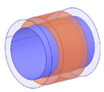 | 360 | 300 W | Low | 77 | [112] |
| Embedded shaped | Medium | 20 kHz | 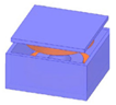 | / | 10 kW | Low | 91 | [68] |
| Medium | Conductivity (S/m) | Relative Permeability | Relative Permittivity |
|---|---|---|---|
| Vacuum | 0 | - | 1 |
| Air | 0 | 1 | 1.0006 |
| Fresh Water | 0.01 | 0.99 | 78.50 |
| Seawater | 4 | 0.99 | 81.50 |
| AUV Type | Type Characteristics | Docking Device Structure | Docking Device Structure | Reference |
|---|---|---|---|---|
| Marine-bird | V-shaped guide rail, two grasping arms | Cushioning locking mechanism type underwater docking platform | Electricity supplementation, data exchange | [147] |
| Bluefin-21 | Maximum diving depth of 4500 m Has a sealed recovery chamber diameter of 0.53 m | Round gradual locking cage box | Electricity supplementation, data exchange | [148] |
| REMUS-100 | A square cage as the guiding mechanism, maximum diving depth of 100 m, diameter of 0.19 m, | Compact splicing device, square progressive locking cage box | Electricity supplementation, data exchange | [130] |
| DAGON | V-shaped clamping mechanism and captured rod | Round construction with locking mechanism | Electricity supplementation, data exchange | [149] |
| Odyssey II | V-shaped titanium latch body and rotatable titanium rod | Round construction with locking mechanism | Electricity supplementation, data exchange | [150] |
Publisher’s Note: MDPI stays neutral with regard to jurisdictional claims in published maps and institutional affiliations. |
© 2022 by the authors. Licensee MDPI, Basel, Switzerland. This article is an open access article distributed under the terms and conditions of the Creative Commons Attribution (CC BY) license (https://creativecommons.org/licenses/by/4.0/).
Share and Cite
Mohsan, S.A.H.; Khan, M.A.; Mazinani, A.; Alsharif, M.H.; Cho, H.-S. Enabling Underwater Wireless Power Transfer towards Sixth Generation (6G) Wireless Networks: Opportunities, Recent Advances, and Technical Challenges. J. Mar. Sci. Eng. 2022, 10, 1282. https://doi.org/10.3390/jmse10091282
Mohsan SAH, Khan MA, Mazinani A, Alsharif MH, Cho H-S. Enabling Underwater Wireless Power Transfer towards Sixth Generation (6G) Wireless Networks: Opportunities, Recent Advances, and Technical Challenges. Journal of Marine Science and Engineering. 2022; 10(9):1282. https://doi.org/10.3390/jmse10091282
Chicago/Turabian StyleMohsan, Syed Agha Hassnain, Muhammad Asghar Khan, Alireza Mazinani, Mohammed H. Alsharif, and Ho-Shin Cho. 2022. "Enabling Underwater Wireless Power Transfer towards Sixth Generation (6G) Wireless Networks: Opportunities, Recent Advances, and Technical Challenges" Journal of Marine Science and Engineering 10, no. 9: 1282. https://doi.org/10.3390/jmse10091282
APA StyleMohsan, S. A. H., Khan, M. A., Mazinani, A., Alsharif, M. H., & Cho, H.-S. (2022). Enabling Underwater Wireless Power Transfer towards Sixth Generation (6G) Wireless Networks: Opportunities, Recent Advances, and Technical Challenges. Journal of Marine Science and Engineering, 10(9), 1282. https://doi.org/10.3390/jmse10091282